EP2730765A1 - Flexibles Leitungselement - Google Patents
Flexibles Leitungselement Download PDFInfo
- Publication number
- EP2730765A1 EP2730765A1 EP20130183517 EP13183517A EP2730765A1 EP 2730765 A1 EP2730765 A1 EP 2730765A1 EP 20130183517 EP20130183517 EP 20130183517 EP 13183517 A EP13183517 A EP 13183517A EP 2730765 A1 EP2730765 A1 EP 2730765A1
- Authority
- EP
- European Patent Office
- Prior art keywords
- conduit
- conduit part
- flexible
- bellows
- flexible conduit
- Prior art date
- Legal status (The legal status is an assumption and is not a legal conclusion. Google has not performed a legal analysis and makes no representation as to the accuracy of the status listed.)
- Granted
Links
Images


Classifications
-
- F—MECHANICAL ENGINEERING; LIGHTING; HEATING; WEAPONS; BLASTING
- F01—MACHINES OR ENGINES IN GENERAL; ENGINE PLANTS IN GENERAL; STEAM ENGINES
- F01N—GAS-FLOW SILENCERS OR EXHAUST APPARATUS FOR MACHINES OR ENGINES IN GENERAL; GAS-FLOW SILENCERS OR EXHAUST APPARATUS FOR INTERNAL-COMBUSTION ENGINES
- F01N13/00—Exhaust or silencing apparatus characterised by constructional features
- F01N13/18—Construction facilitating manufacture, assembly, or disassembly
- F01N13/1805—Fixing exhaust manifolds, exhaust pipes or pipe sections to each other, to engine or to vehicle body
- F01N13/1811—Fixing exhaust manifolds, exhaust pipes or pipe sections to each other, to engine or to vehicle body with means permitting relative movement, e.g. compensation of thermal expansion or vibration
- F01N13/1816—Fixing exhaust manifolds, exhaust pipes or pipe sections to each other, to engine or to vehicle body with means permitting relative movement, e.g. compensation of thermal expansion or vibration the pipe sections being joined together by flexible tubular elements only, e.g. using bellows or strip-wound pipes
-
- F—MECHANICAL ENGINEERING; LIGHTING; HEATING; WEAPONS; BLASTING
- F16—ENGINEERING ELEMENTS AND UNITS; GENERAL MEASURES FOR PRODUCING AND MAINTAINING EFFECTIVE FUNCTIONING OF MACHINES OR INSTALLATIONS; THERMAL INSULATION IN GENERAL
- F16L—PIPES; JOINTS OR FITTINGS FOR PIPES; SUPPORTS FOR PIPES, CABLES OR PROTECTIVE TUBING; MEANS FOR THERMAL INSULATION IN GENERAL
- F16L27/00—Adjustable joints; Joints allowing movement
- F16L27/10—Adjustable joints; Joints allowing movement comprising a flexible connection only
- F16L27/1004—Adjustable joints; Joints allowing movement comprising a flexible connection only introduced in exhaust pipes for hot gases
-
- F—MECHANICAL ENGINEERING; LIGHTING; HEATING; WEAPONS; BLASTING
- F16—ENGINEERING ELEMENTS AND UNITS; GENERAL MEASURES FOR PRODUCING AND MAINTAINING EFFECTIVE FUNCTIONING OF MACHINES OR INSTALLATIONS; THERMAL INSULATION IN GENERAL
- F16L—PIPES; JOINTS OR FITTINGS FOR PIPES; SUPPORTS FOR PIPES, CABLES OR PROTECTIVE TUBING; MEANS FOR THERMAL INSULATION IN GENERAL
- F16L27/00—Adjustable joints; Joints allowing movement
- F16L27/10—Adjustable joints; Joints allowing movement comprising a flexible connection only
- F16L27/107—Adjustable joints; Joints allowing movement comprising a flexible connection only the ends of the pipe being interconnected by a flexible sleeve
- F16L27/11—Adjustable joints; Joints allowing movement comprising a flexible connection only the ends of the pipe being interconnected by a flexible sleeve the sleeve having the form of a bellows with multiple corrugations
-
- F—MECHANICAL ENGINEERING; LIGHTING; HEATING; WEAPONS; BLASTING
- F16—ENGINEERING ELEMENTS AND UNITS; GENERAL MEASURES FOR PRODUCING AND MAINTAINING EFFECTIVE FUNCTIONING OF MACHINES OR INSTALLATIONS; THERMAL INSULATION IN GENERAL
- F16L—PIPES; JOINTS OR FITTINGS FOR PIPES; SUPPORTS FOR PIPES, CABLES OR PROTECTIVE TUBING; MEANS FOR THERMAL INSULATION IN GENERAL
- F16L51/00—Expansion-compensation arrangements for pipe-lines
- F16L51/02—Expansion-compensation arrangements for pipe-lines making use of a bellows or an expansible folded or corrugated tube
- F16L51/025—Expansion-compensation arrangements for pipe-lines making use of a bellows or an expansible folded or corrugated tube with several corrugations
-
- F—MECHANICAL ENGINEERING; LIGHTING; HEATING; WEAPONS; BLASTING
- F16—ENGINEERING ELEMENTS AND UNITS; GENERAL MEASURES FOR PRODUCING AND MAINTAINING EFFECTIVE FUNCTIONING OF MACHINES OR INSTALLATIONS; THERMAL INSULATION IN GENERAL
- F16L—PIPES; JOINTS OR FITTINGS FOR PIPES; SUPPORTS FOR PIPES, CABLES OR PROTECTIVE TUBING; MEANS FOR THERMAL INSULATION IN GENERAL
- F16L51/00—Expansion-compensation arrangements for pipe-lines
- F16L51/02—Expansion-compensation arrangements for pipe-lines making use of a bellows or an expansible folded or corrugated tube
- F16L51/03—Expansion-compensation arrangements for pipe-lines making use of a bellows or an expansible folded or corrugated tube comprising two or more bellows
-
- F—MECHANICAL ENGINEERING; LIGHTING; HEATING; WEAPONS; BLASTING
- F01—MACHINES OR ENGINES IN GENERAL; ENGINE PLANTS IN GENERAL; STEAM ENGINES
- F01N—GAS-FLOW SILENCERS OR EXHAUST APPARATUS FOR MACHINES OR ENGINES IN GENERAL; GAS-FLOW SILENCERS OR EXHAUST APPARATUS FOR INTERNAL-COMBUSTION ENGINES
- F01N13/00—Exhaust or silencing apparatus characterised by constructional features
- F01N13/14—Exhaust or silencing apparatus characterised by constructional features having thermal insulation
- F01N13/141—Double-walled exhaust pipes or housings
- F01N13/143—Double-walled exhaust pipes or housings with air filling the space between both walls
-
- F—MECHANICAL ENGINEERING; LIGHTING; HEATING; WEAPONS; BLASTING
- F01—MACHINES OR ENGINES IN GENERAL; ENGINE PLANTS IN GENERAL; STEAM ENGINES
- F01N—GAS-FLOW SILENCERS OR EXHAUST APPARATUS FOR MACHINES OR ENGINES IN GENERAL; GAS-FLOW SILENCERS OR EXHAUST APPARATUS FOR INTERNAL-COMBUSTION ENGINES
- F01N2310/00—Selection of sound absorbing or insulating material
- F01N2310/02—Mineral wool, e.g. glass wool, rock wool, asbestos or the like
-
- F—MECHANICAL ENGINEERING; LIGHTING; HEATING; WEAPONS; BLASTING
- F01—MACHINES OR ENGINES IN GENERAL; ENGINE PLANTS IN GENERAL; STEAM ENGINES
- F01N—GAS-FLOW SILENCERS OR EXHAUST APPARATUS FOR MACHINES OR ENGINES IN GENERAL; GAS-FLOW SILENCERS OR EXHAUST APPARATUS FOR INTERNAL-COMBUSTION ENGINES
- F01N2310/00—Selection of sound absorbing or insulating material
- F01N2310/14—Wire mesh fabric, woven glass cloth or the like
Definitions
- the invention relates to a flexible conduit element, in particular a decoupling element, for an exhaust system of a motor vehicle.
- Flexible conduit elements are used for example in the form of Entkoppeleiementen in exhaust pipes of motor vehicles to decouple engine vibrations and other harmful movements of the exhaust system.
- Such a flexible conduit element for use in an exhaust system of motor vehicles is for example out DE 203 02 657 U1 known.
- a metal hose is arranged inside a helical or ring-shaped metal bellows.
- a spacer made of woven or knitted fabric is further provided for damping purposes.
- the metal tube is usually formed as a winding tube and is used as the liner lining the metal bellows inside.
- this also fulfills the purpose of the insulation.
- urea or HC hydrocarbon, eg diesel fuel
- HC hydrocarbon, eg diesel fuel
- the invention thus provides a flexible conduit element, in particular a decoupling element for an exhaust system of a motor vehicle, which has an inner conduit part and an outer conduit part, wherein the outer conduit part surrounds the inner conduit part at a predetermined distance, so that between the inner and the outer conduit part a Interspace is present, wherein the inner conduit part is gas-tight and has a bellows portion.
- an insulated decoupling element in which urea or HC can also be used without any problems immediately before the decoupling element, since the injected substances do not penetrate the gas-tight inner component, wherein in the decoupling element, ie deposits formed within the inner pipe part in the waves of the inner metal bellows are easier to redissolve, for example, by strong heating at high speed (highway), as in the turns of a winding tube.
- the corrugation of the inner Balgabitess leads on the one hand just in the course of the injection of urea or HC to the fact that the exhaust gas and the injected substance are optimally swirled.
- the thus formed flexible conduit member can accommodate large movements.
- Another advantage is the acoustic isolation achieved by an air gap in the space between the inner pipe part and the outer pipe part.
- the inner pipe part is a bellows or corrugated metal hose and the outer pipe part is also a metal bellows or corrugated hose.
- the outer bellows and the inner bellows create, as stated above, the advantage that deposits, which are formed for example by urea, from the waves of the inner bellows, which is used instead of a winding tube, are easier to remove than from the interstices of the windings, for example, a winding tube .
- the outer bellows and the inner bellows are preferably matched with respect to their mechanical, geometric and dynamic properties.
- the inner conduit part is an inner bellows
- the outer conduit part is a winding tube
- an insulating means is disposed in the space between the inner pipe part and the outer pipe part, which provides acoustic and thermal insulation of the flexible pipe member.
- the insulating means is air.
- air as the insulator allows both the maintenance of the flexibility of the conduit member and the assurance of thermal stability of the insulation. Since no friction occurs in this case, this form of insulation can be used for decoupling, on which large movements occur, in which case no wear due to friction occurs.
- material isolation may also be provided between the inner and outer components, as this is a closed system in which there will be little or no wear on the intermediate insulation materials. Examples of insulating materials are glass fiber material or basalt stone wool, without this list being exhaustive.
- the outer conduit part has a first and a second (smooth) cylindrical end portion at its respective ends.
- the bellows portion of the inner pipe part is arranged approximately centrally between a first (smooth) cylindrical end portion and a second (smooth) cylindrical end portion of the first pipe part, which end portions each with a fastening or connecting means for fixing the inner Line parts are provided on the outer pipe part.
- the two end portions and correspondingly the attachment / connection means need not be identical.
- the fastening device comprises a U-profile, in particular an axially elongated U-profile.
- “Axially extended” here means that one (free) leg of the U-profile is formed longer than the other (free) leg, the entire profile with its (free) legs is arranged approximately in the direction of the longitudinal extent (longitudinal axis) of the conduit element ,
- the U-profile is connected with a first leg to the first cylindrical end portion of the inner pipe part and with a second leg to the cylindrical end portion of the outer pipe part.
- the axially elongated U-profile may have an extension which is provided on the first, inner leg.
- the axial extension can advantageously connecting elements, d. H. further (pipe) line elements of the exhaust system or the like can be arranged.
- the inner, extended leg can have at least sections, a radial extension component to the outside.
- a sealing ring in particular made of graphite, is arranged between the inner conduit part and the outer conduit part in the region of the respective first and / or second end sections.
- this embodiment is not limited to the fact that said sealing rings must be present at both ends. Rather, both ends can also be designed differently.
- the outer conduit part can be surrounded by an end sleeve at least at one of the first and second end sections, to which a further (pipe) conduit element can be connected.
- another (pipe) line element can also be connected to the U-profile.
- the inner pipe part and the outer pipe part may further have different lengths.
- the inner pipe part and / or the outer pipe part are provided with a coating.
- the inner surfaces of the inner lead portion and / or the outer lead portion may be blackened to achieve better absorption of heat, depending on the application.
- the outer pipe part is at least partially surrounded by an outer component, in particular by an outer liner (winding hose), a knitted fabric, a braid or a shrink tube, in order to prevent contamination of the bellows.
- an outer component improves the aesthetics of the conduit member as well as the damping effect.
- Fig. 1 shows a partially sectioned view of a decoupling element 1 for an exhaust system of a formed flexible conduit element 2 according to one embodiment.
- the flexible conduit member 2 has an inner conduit part 3 and an outer conduit part 4 which surrounds the inner conduit part 3 at a predetermined distance 5, so that between the inner conduit part 3 and the outer conduit part 4, a gap 6 is formed in which air as Insulating agent is included.
- Both the inner conduit part 3 and the outer conduit part 4 have a bellows section only partially shown here, wherein the bellows section of the inner conduit part 3 is denoted by the reference numeral 7 and the bellows section of the outer conduit part 4 by the reference numeral 8.
- Each of the bellows sections 7, 8 is arranged centrally between two cylindrical end sections and extends substantially over the entire length of the decoupling element 1.
- the bellows section 7 of the inner line section 3 is arranged between a first cylindrical end section 9 and a second cylindrical end section 10, and the bellows portion 8 of the outer pipe part 4 is arranged between a first cylindrical end portion 11 and a second cylindrical end portion 12.
- a fastening or connecting device 13, 13 ' is arranged in each case to fasten the inner pipe part 3 to the outer pipe part 4.
- the fastening devices 13, 13 ' are each formed as U-profiles and arranged at the edge of the first cylindrical end portions 9, 11 and the second cylindrical end portions 10, 12, so that the ends of the free legs of the U-profiles together with said end portions Complete 9-12.
- This is shown in detail again in the enlarged section, which is indicated by the reference numeral 14.
- a first, inner leg 20 of the U-profile is connected to the first cylindrical end portion 9 of the inner pipe part 3, z. B. welded, and a second, outer leg 21 of the U-profile is connected or welded to the cylindrical end portion 11 of the outer pipe part 4.
- the middle leg 13a of the profile ensures the distance between the line parts 3, 4; its extension in the radial direction is greater than the bellows shaft height in the bellows section 7 of the inner pipe part 3.
- Reference numeral 15 denotes an end sleeve for the connection of the outer bellows 4. This End sleeve 15 can serve for tying an additional outer component (winding tube, braid, knitted fabric ...) (not shown).
- Fig. 2 shows a partially sectioned view of a flexible conduit member 2 according to another embodiment, As can be seen here, is attached to the fastening device 13 via the U-profile, an expanding connecting element 14.
- the connection element 14 is welded on the left side of the drawing to an inner wall 22 of the second leg 21 of the U-profile.
- the connection element 14 'on the right side of the drawing is directly connected or welded to an outer wall 23 of the end sleeve 15.
- To the connection elements 14, 14 'further line elements of the exhaust system, which are not shown here, or the like can be connected.
- a sealing element 16 such as a sealing ring made of graphite inserted.
- the invention is not limited thereto.
- the sealing element 16 may, for. B. also in the embodiment according to FIG. 1 Find application, as all shown or described Endanitatisart the conduit parts 3, 4 are basically interchangeable and combinable.
- Fig. 3 shows a partially sectioned view of a decoupling element 1 formed as a flexible conduit element 2 according to another embodiment, which differs from the in FIG. 1 illustrated embodiment differs in that here as outer conduit part 4 instead of the metal bellows, a winding tube 17 is provided (see also FIG. 4 ).
- the inner pipe part 3 is still formed as a metal bellows or with a bellows portion 7, so that the gap 6 between the inner pipe part 3 and the outer pipe part 4 is sealed inwardly.
- the gas or exhaust gas is guided in the interior of the decoupling element 1 through the metal bellows 7, and any deposits can be easily removed again.
- the winding tube 17, which forms the outer conduit part 4 is connected with its end portions under end sleeves 18 and 18 'via the U-shaped fastening means 13 and 13' with the inner conduit part 3.
- a first leg 20 or 20 'of the fastening device 13 or 13' with the cylindrical end portion 9 and 10 of the inner pipe part 3 is connected or welded thereto, and the second leg 21 is connected to the cylindrical end portion 11, 12 of the winding tube 17 and or an end sleeve 18 or 18 'or welded thereto.
- Fig. 4 is also a partially sectioned view of a flexible conduit member 1 according to yet another embodiment, which is also equipped with a winding tube 17 as an outer conduit part 4.
- the embodiment illustrated here differs from that in FIG. 3 illustrated embodiment in that the fastening means 13 and 13 'has an integrally formed axial extension 24, 24' on the first leg 20 and 20 ', which are at least functionally approximately analogous to the connection elements 14, 14' are formed (see. FIG. 2 ).
- Said axial extensions 24, 24 ' have in sections at their free ends a radial extension component, so that the clear cross section correspondingly widens, as shown.
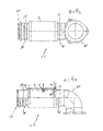
- FIGS. 5A and 5B show respective views of a decoupling element 1 formed as a flexible conduit element 2, as for example in FIG. 4 is shown, wherein FIG. 5A a partially sectioned side view and FIG. 5B is a top view.
- the decoupling element 1 is in this case connected to a further connecting part 19, here with a connecting tube bent about 90 ° (exhaust manifold), for arranging the decoupling element 1 in an exhaust gas line.
- the connecting part 19 is attached to or welded to the extension 24 of the first leg 20 of the fastening device 13, which extension 24 forms the connecting element 14.
- Reference numeral 25 denotes a further conduit element 25 of the exhaust system, which is connected to the extension 24 '.
Landscapes
- Engineering & Computer Science (AREA)
- General Engineering & Computer Science (AREA)
- Mechanical Engineering (AREA)
- Chemical & Material Sciences (AREA)
- Combustion & Propulsion (AREA)
- Exhaust Silencers (AREA)
Description
- Die Erfindung betrifft ein flexibles Leitungselement, insbesondere ein Entkoppelelement, für eine Abgasanlage eines Kraftfahrzeugs.
- Flexible Leitungselemente werden beispielsweise in Form von Entkoppeleiementen in Abgasleitungen von Kraftfahrzeugen eingesetzt, um Motorschwingungen und andere schädliche Bewegungen von der Abgasanlage zu entkoppeln.
- Ein derartiges flexibles Leitungselement zur Verwendung in einer Abgasanlage von Kraftfahrzeugen ist beispielsweise aus
DE 203 02 657 U1 bekannt. Hier ist im Inneren eines schraubengangförmigen oder ringgewellten Metallbalgs ein Metallschlauch angeordnet. Zwischen dem Metallschlauch und dem Metallbalg ist weiterhin ein Abstandshalter aus Gewebe oder Gestricke zu Dämpfungszwecken vorgesehen. - Wie auch bei dem oben genannten Stand der Technik ist üblicherweise der Metallschlauch als Wickelschlauch ausgebildet und wird als den Metallbalg innen auskleidender Liner verwendet. Dieser erfüllt dann neben dem ursprünglichen Verwendungszweck, nämlich der Optimierung der Strömung, der Akustik, etc. innerhalb des Balgs, auch den Zweck der Isolierung.
- Aufgrund der verschärften Abgasgesetzgebung wird heutzutage vermehrt Harnstoff oder HC (Kohlenwasserstoff, z. B. Dieselkraftstoff) zur Abgasnachbehandlung eingesetzt. Wird der Harnstoff oder der Kohlenwasserstoff vor dem Entkoppelelement, d. h. dem Metallbalg mit innenliegendem Liner "eingedüst", kann er sich in den Agraffen bzw. Zwischenräumen des Liners absetzen und dort auskristallisieren. Hierdurch wird die Beweglichkeit des Liners beeinträchtigt oder geht vollständig verloren. Dies kann zu einem wesentlich früheren Ausfalls des Liners und des gesamten Bauteils führen. Auch kann sich der Harnstoff oder Kohlenwasserstoff zwischen dem Balg und dem Liner ablagern und dort auskristallisieren, da es sich bei einem als Wickelschlauch ausgebildeten Metallschlauch um kein vollständig dichtes Bauteil handelt. Hierdurch kann nicht nur der Liner verfrüht ausfallen, sondern auch der Metallbalg beschädigt werden. Die Abgastemperatur reicht häufig in beiden Fällen nicht aus, um den Harnstoff bzw. Kohlenwasserstoff durch Erhitzen zu verdampfen, was unweigerlich zu einer Verkürzung der Lebensdauer der Gesamtbauteils führt.
- Daher ist es eine Aufgabe der vorliegenden Erfindung, ein flexibles Leitungselement, insbesondere für einen Entkoppler einer Abgasanlage in einem Kraftfahrzeug, bereitzustellen, bei welchem Ablagerungen beispielsweise durch Harnstoff oder HC reduziert, aufgelöst oder gänzlich vermieden werden können, um die Lebensdauer des Bauteils zu verlängern.
- Die Aufgabe der Erfindung wird durch ein flexibles Leitungselement mit den Merkmalen gemäß Anspruch 1 gelöst. Vorteilhafte Weiterbildungen der Erfindung sind in den abhängigen Ansprüchen definiert.
- Erfindungsgemäß bereitgestellt wird also ein flexibles Leitungselement, insbesondere ein Entkoppelelement für eine Abgasanlage eines Kraftfahrzeugs, welches ein inneres Leitungsteil und ein äußeres Leitungsteil aufweist, wobei das äußere Leitungsteil das innere Leitungsteil in einem vorbestimmten Abstand umgibt, so dass zwischen dem inneren und dem äußeren Leitungsteil ein Zwischenraum vorhanden ist, wobei das innere Leitungsteil gasdicht ausgebildet ist und einen Balgabschnitt aufweist. Durch die erfindungsgemäße Konfiguration, bei der als inneres Leitungsteil eine gasdichte Innenkomponente mit Balgabschnitt eingesetzt wird, kann ein isoliertes Entkoppelelement realisiert werden, bei welchem Harnstoff oder HC unproblematisch auch unmittelbar vor dem Entkoppelelement einsetzbar ist, da die eingedüsten Stoffe die gasdichte Innenkomponente nicht durchdringen, wobei in dem Entkoppelelement, d. h. innerhalb des inneren Leitungsteils gebildete Ablagerungen in den Wellen des inneren Metallbalgs leichter wieder auflösbar sind, beispielsweise durch starkes Erhitzen bei Schnellfahrt (Autobahn), als in den Windungen eines Wickelschlauchs. Die Wellung des inneren Balgabschnitts führt einerseits gerade im Zuge der Eindüsung von Harnstoff oder HC dazu, dass das Abgas und der eingedüste Stoff optimal verwirbelt werden. In diesem Zusammenhang ist es also sogar vorteilhaft, wenn keine definierte Strömungsführung, wie sie durch einen herkömmlichen, beispielsweise als Wickelschlauch ausgeführten Innenliner realisiert wird, innerhalb des Entkoppelelements gegeben ist. Wenn andererseits der innere Leitungsabschnitt, welcher einen Balgabschnitt aufweist, unmittelbar als eigentliches Leitungselement für den Abgasstrom Verwendung findet, können zwar weiterhin Ablagerungen auftreten, diese sind jedoch unkritisch, da während der normalen Betriebszyklen eines Abgasstranges in regelmäßigen Abständen, beispielsweise bei schnellen Autobahnfahrten, ein starkes Erhitzten des gesamten Abgasstranges erfolgt, wodurch die Ablagerungen (durch Verdampfen) wieder vom Balg gelöst werden, worauf bereits hingewiesen wurde. Wenn hier, wie beim Stand der Technik, jedoch ein Wickelschlauch als Innenkomponente verwendet würde, blieben die Ablagerungen in den Freiräumen des Wickelschlauchs erhalten oder könnten sogar in den Bereich zwischen Wickelschlauch und Balg gelangen, was die Lebensdauer und sonstigen Eigenschaften der Anordnung negativ beeinflussen würde.
- Außerdem kann das so ausgebildete flexible Leitungselement große Bewegungen aufnehmen. Ein weiterer Vorteil ist die akustische Isolierung, die durch einen Luftspalt in dem Zwischenraum zwischen dem inneren Leitungsteil und dem äußeren Leitungsteil erreicht wird.
- Gemäß einer bevorzugten Ausführungsform ist das innere Leitungsteil ein Balg oder Ringwellschlauch aus Metall und das äußere Leitungsteil ebenfalls ein Balg oder Ringwellschlauch aus Metall. Der Außenbalg und der Innenbalg schaffen, wie oben bereits ausgeführt, den Vorteil, dass Ablagerungen, welche beispielsweise durch Harnstoff gebildet werden, aus den Wellen des Innenbalgs, welcher anstelle eines Wickelschlauchs verwendet wird, leichter entfernbar sind als aus den Zwischenräumen der Windungen beispielsweise eines Wickelschlauchs. Der Außenbalg und der Innenbalg sind vorzugsweise hinsichtlich ihrer mechanischen, geometrischen und dynamischen Eigenschaften aufeinander abgestimmt. Darüber hinaus bietet die Verwendung eines Metallbalgs als inneres Leitungsteil anstelle eines Wickelschlauchs den Vorteil, dass der innere Metallbalg vollständig dicht ist, so dass kein Harnstoff in den Zwischenraum zwischen innerem und äußerem Metallbalg gelangen und sich dort ablagern kann. Hierauf wurde oben schon detailliert hingewiesen.
- Gemäß einer weiteren bevorzugten Ausführungsform ist das innere Leitungsteil ein Innenbalg, und das äußere Leitungsteil ist ein Wickelschlauch. Hierdurch werden die oben bereits ausgeführten Vorteile erzielt, da sich die Gefahr der Bildung von Ablagerungen im Bereich der Innenkomponente oder im Zwischenraum zwischen innerem und äußerem Leitungsteil stark reduziert.
- Gemäß noch einer bevorzugten Ausführungsform ist in dem Zwischenraum zwischen dem inneren Leitungsteil und dem äußeren Leitungsteil ein Isoliermittel angeordnet, was für eine akustische und thermische Isolierung des flexiblen Leitungselements sorgt.
- Gemäß noch einer weiteren bevorzugten Ausführungsform ist das Isoliermittel Luft. Das Verwenden von Luft als Isoliermittel ermöglicht sowohl die Aufrechterhaltung der Flexibilität des Leitungselements als auch die Gewährleistung der Temperaturbeständigkeit der Isolierung. Da in diesem Fall keine Reibung auftritt, kann diese Form der Isolierung für Entkoppelelemente verwendet werden, an welchen große Bewegungen auftreten, wobei dann kein Verschleiß durch Reibung auftritt. Es kann jedoch auch eine stoffliche Isolation zwischen der inneren und äußeren Komponente vorgesehen werden, da es sich hier um ein geschlossenes System handelt, in dem es lediglich geringen oder keinen Verschleiß der zwischenliegenden lsolationsmaterialien geben wird. Beispiele für Isolationsstoffe sind Glasfasermaterial oder Basaltsteinwolle, ohne dass diese Aufzählung abschließend wäre.
- Gemäß noch einer weiteren bevorzugten Ausführungsform weist das äußere Leitungsteil einen ersten und einen zweiten (glatt-)zylindrischen Endabschnitt an seinen jeweiligen Enden auf.
- Ferner ist es vorteilhaft, wenn der Balgabschnitt des inneren Leitungsteils etwa mittig zwischen einem ersten (glatt-)zylindrischen Endabschnitt und einem zweiten (glatt-)zylindrischen Endabschnitt des ersten Leitungsteils angeordnet ist, welche Endabschnitte jeweils mit einer Befestigungs- oder Verbindungseinrichtung zum Befestigen des inneren Leitungsteils an dem äußeren Leitungsteil versehen sind. Die beiden Endabschnitte und entsprechend die Befestigungs-/Verbindungsein-richtungen müssen nicht identisch ausgebildet sein. Vorzugsweise umfasst die Befestigungseinrichtung ein U-Profil, insbesondere ein axial verlängertes U-Profil. "Axial verlängert" bedeutet hierbei, dass ein (freier) Schenkel des U-Profils länger ausgebildet ist als der andere (freie) Schenkel, wobei das gesamte Profil mit seinen (freien) Schenkeln etwa in Richtung der Längserstreckung (Längsachse) des Leitungselements angeordnet ist.
- Gemäß noch einer weiteren bevorzugten Ausführungsform ist das U-Profil mit einem ersten Schenkel an den ersten zylindrischen Endabschnitt des inneren Leitungsteils angebunden und mit einem zweiten Schenkel an den zylindrischen Endabschnitt des äußeren Leitungsteils. Die so erzielte Anbindung des inneren Leitungsteils an das äußere Leitungsteil ist mittels des U-Profils besonders vorteilhaft und einfach realisierbar. Über seinen mittleren Schenkel sorgt das U-Profil hierbei für den nötigen Abstand zwischen den beiden Leitungsteilen.
- Darüber hinaus kann das axial verlängerte U-Profil eine Verlängerung aufweisen, welche an dem ersten, inneren Schenkel vorgesehen ist. An der axialen Verlängerung können vorteilhafterweise Anschlusselemente, d. h. weitere (Rohr-)Leitungs-elemente des Abgasstrangs oder dergleichen angeordnet werden. Der innere, verlängerte Schenkel kann dabei zumindest abschnittweise eine radiale Erstreckungskomponente nach außen aufweisen.
- Von Vorteil ist auch, wenn zwischen dem inneren Leitungsteil und dem äußeren Leitungsteil im Bereich der jeweiligen ersten und/oder zweiten Endabschnitte jeweils ein Dichtring, insbesondere aus Graphit, angeordnet ist. Diese Ausgestaltung ist jedoch nicht darauf beschränkt, dass an beiden Enden die genannten Dichtringe vorhanden sein müssen. Vielmehr können beide Enden auch verschieden ausgebildet sein.
- Darüber hinaus kann das äußere Leitungsteil zumindest an einem der ersten und zweiten Endabschnitte von einer Endhülse umgeben sein, an welche ein weiteres (Rohr-)Leitungselement anbindbar ist.
- Vorzugsweise ist auch an dem U-Profil ein weiteres (Rohr-)Leitungselement anbindbar.
- Vorzugsweise können das innere Leitungsteil und das äußere Leitungsteil darüber hinaus unterschiedliche Längen aufweisen.
- Weiterhin ist es von Vorteil, wenn bestimmte Oberflächen des inneren Leitungsteils und/oder des äußeren Leitungsteils mit einer Beschichtung versehen sind. Beispielsweise können die inneren Oberflächen des inneren Leitungsteils und/oder des äußeren Leitungsteils geschwärzt sein, um eine bessere Absorption von Wärme, je nach Anwendung, zu erzielen.
- Gemäß einer weiteren bevorzugten Ausführungsform ist das äußere Leitungsteil zumindest teilweise von einer Außenkomponente, insbesondere von einem Außenliner (Wickelschlauch), einem Gestricke, einem Geflecht oder einem Schrumpfschlauch, umgeben, um eine Verschmutzung des Balgs zu verhindern. Auch verbessert eine zusätzliche Außenkomponente die Ästhetik des Leitungselements sowie die Dämpfungswirkung.
- Weitere Merkmale und Vorteile der vorliegenden Erfindung ergeben sich aus der nachfolgenden Beschreibung von Ausführungsbeispielen anhand der Zeichnung; hierbei zeigt:
- Fig. 1
- eine teilweise geschnittene Ansicht eines flexiblen Leitungselements gemäß einer Ausführungsform;
- Fig. 2
- eine teilweise geschnittene Ansicht eines flexiblen Leitungselements gemäß einer weiteren Ausführungsform;
- Fig. 3
- eine teilweise geschnittene Ansicht eines flexiblen Leitungselements gemäß einer alternativen Ausführungsform;
- Fig. 4
- eine teilweise geschnittene Ansicht eines flexiblen Leitungselements gemäß noch einer weiteren Ausführungsform;
- Fig. 5A, 5B
- jeweilige Ansichten eines als Entkoppelelement ausgebildeten flexiblen Leitungselements, an welches Verbindungsteile angeschlossen sind.
-
Fig. 1 zeigt eine teilweise geschnittene Ansicht eines als Entkoppelelement 1 für eine Abgasanlage eines ausgebildeten flexiblen Leitungselements 2 gemäß einer Ausführungsform. Das flexible Leitungselement 2 weist ein inneres Leitungsteil 3 und ein äußeres Leitungsteil 4 auf, welches das innere Leitungsteil 3 in einem vorbestimmten Abstand 5 umgibt, so dass zwischen dem inneren Leitungsteil 3 und dem äußeren Leitungsteil 4 ein Zwischenraum 6 gebildet ist, in welchem Luft als Isoliermittel eingeschlossen ist. Sowohl das innere Leitungsteil 3 als auch das äußere Leitungsteil 4 weist einen hier nur ausschnittsweise dargestellten Balgabschnitt auf, wobei der Balgabschnitt des inneren Leitungsteils 3 mit dem Bezugszeichen 7 und der Balgabschnitt des äußeren Leitungsteils 4 mit dem Bezugszeichen 8 gekennzeichnet ist. Jeder der Balgabschnitte 7, 8 ist mittig zwischen zwei zylindrischen Endabschnitten angeordnet und erstreckt sich im Wesentlichen über die gesamte Länge des Entkoppelelements 1. Dabei ist der Balgabschnitt 7 des inneren Leitungsteils 3 zwischen einem ersten zylindrischen Endabschnitt 9 und einem zweiten zylindrischen Endabschnitt 10 angeordnet, und der Balgabschnitt 8 des äußeren Leitungsteils 4 ist zwischen einem ersten zylindrischen Endabschnitt 11 und einem zweiten zylindrischen Endabschnitt 12 angeordnet. An bzw. zwischen den ersten zylindrischen Endabschnitten 9, 11 und den zweiten zylindrischen Endabschnitten 10, 12 ist jeweils eine Befestigungs- oder Verbindungseinrichtung 13, 13' angeordnet, um das innere Leitungsteil 3 an dem äußeren Leitungsteil 4 zu befestigen. Die Befestigungseinrichtungen 13, 13' sind jeweils als U-Profile ausgebildet und am Rand der ersten zylindrischen Endabschnitte 9, 11 bzw. der zweiten zylindrischen Endabschnitte 10, 12 angeordnet, so dass die Enden der freien Schenkel der U-Profile gemeinsam mit den genannten Endabschnitten 9-12 abschließen. Dies ist im Detail nochmals in dem vergrößerten Ausschnitt, der durch das Bezugszeichen 14 gekennzeichnet ist, gezeigt. Wie in der Detailansicht 14 erkennbar ist, ist dabei ein erster, innerer Schenkel 20 des U-Profils an den ersten zylindrischen Endabschnitt 9 des inneren Leitungsteils 3 angebunden, z. B. angeschweißt, und ein zweiter, äußerer Schenkel 21 des U-Profils ist an den zylindrischen Endabschnitt 11 des äußeren Leitungsteils 4 angebunden bzw. angeschweißt. Der mittlere Schenkel 13a des Profils sorgt für den Abstand zwischen den Leitungsteilen 3, 4; seine Erstreckung in radialer Richtung ist größer als die Balgwellenhöhe im Balgabschnitt 7 des inneren Leitungsteils 3. Bezugszeichen 15 kennzeichnet eine Endhülse für die Anbindung des Außenbalgs 4. Diese Endhülse 15 kann zum Anbinden einer zusätzlichen Außenkomponente (Wickelschlauch, Geflecht, Gestricke ...) dienen (nicht gezeigt). -
Fig. 2 zeigt eine teilweise geschnittene Ansicht eines flexiblen Leitungselements 2 gemäß einer weiteren Ausführungsform, Wie hier erkennbar ist, ist an der Befestigungseinrichtung 13 über das U-Profil ein sich erweiterndes Anschlusselement 14 angebunden. Hierzu ist das Anschlusselement 14 auf der linken Seite der Zeichnung an eine Innenwand 22 des zweiten Schenkels 21 des U-Profils angeschweißt. Das Anschlusselement 14' auf der rechten Seite der Zeichnung ist dagegen direkt an eine Außenwand 23 der Endhülse 15 angebunden bzw. angeschweißt. An die Anschlusselemente 14, 14' können weitere Leitungselemente der Abgasanlage, welche hier nicht dargestellt sind, oder dergleichen angeschlossen werden. Weiterhin ist zwischen den zylindrischen Endabschnitten 10 und 12 des inneren Leitungsteils 3 bzw. des äußeren Leitungsteils 4 auf der rechten Seite der Anordnung alternativ zu dem U-Profil auf der anderen Seite ein Dichtelement 16, wie beispielsweise ein Dichtring aus Graphit, eingefügt. Die Erfindung ist hierauf nicht beschränkt. Das Dichtelement 16 kann z. B. auch bei der Ausgestaltung gemäßFigur 1 Anwendung finden, wie überhaupt alle gezeigten oder beschriebenen Endanbindungsarten der Leitungsteile 3, 4 grundsätzlich austauschbar und kombinierbar sind. -
Fig. 3 zeigt eine teilweise geschnittene Ansicht eines als Entkoppelelement 1 ausgebildeten flexiblen Leitungselements 2 gemäß einer weiteren Ausführungsform, welches sich von der inFigur 1 dargestellten Ausführungsform dadurch unterscheidet, dass hier als äußeres Leitungsteil 4 anstelle des Metallbalgs ein Wickelschlauch 17 vorgesehen ist (vgl. auchFigur 4 ). Das innere Leitungsteil 3 ist jedoch nach wie vor als Metallbalg bzw. mit einem Balgabschnitt 7 ausgebildet, so dass der Zwischenraum 6 zwischen dem inneren Leitungsteil 3 und dem äußeren Leitungsteil 4 nach innen abgedichtet ist. Auch hier wird das Gas oder Abgas im Inneren des Entkoppelelements 1 durch den Metallbalg 7 geführt, und eventuelle Ablagerungen können leicht wieder entfernt werden. Der Wickelschlauch 17, welcher das äußere Leitungsteil 4 bildet, wird mit seinem Endabschnitten unter Endhülsen 18 bzw. 18' über die U-förmige Befestigungseinrichtung 13 bzw. 13' mit dem inneren Leitungsteil 3 verbunden. Hierzu ist wiederum ein erster Schenkel 20 bzw. 20' der Befestigungseinrichtung 13 bzw. 13' mit dem zylindrischen Endabschnitt 9 bzw. 10 des inneren Leitungsteils 3 verbunden bzw. daran angeschweißt, und der zweite Schenkel 21 ist mit dem zylindrischen Endabschnitt 11, 12 des Wickelschlauchs 17 und oder einer Endhülse 18 bzw. 18' verbunden bzw. daran angeschweißt. -
Fig. 4 ist ebenfalls eine teilweise geschnittene Ansicht eines flexiblen Leitungselements 1 gemäß noch einer weiteren Ausführungsform, welche auch mit einem Wickelschlauch 17 als äußeres Leitungsteil 4 ausgestattet ist. Die hier dargestellte Ausführungsform unterscheidet sich jedoch von der inFigur 3 dargestellten Ausführungsform dadurch, dass die Befestigungseinrichtung 13 bzw. 13' eine einstückig angeformte axiale Verlängerung 24, 24' an dem ersten Schenkel 20 bzw. 20' aufweist, welche zumindest funktional etwa analog zu den Anschlusselementen 14, 14' ausgebildet sind (vgl.Figur 2 ). Die genannten axialen Verlängerungen 24, 24' besitzen zu ihren freien Enden hin abschnittweise eine radiale Erstreckungskomponente, so dass sich der lichte Querschnitt entsprechend erweitert, wie dargestellt. -
Figuren 5A und 5B zeigen jeweilige Ansichten eines als Entkoppelelement 1 ausgebildeten flexiblen Leitungselements 2, wie es beispielsweise inFigur 4 dargestellt ist, wobeiFigur 5A eine teilweise geschnittene Seitenansicht undFigur 5B eine Draufsicht ist. Das Entkoppelelement 1 ist hier mit einem weiteren Verbindungsteil 19, hier mit einem etwa um 90° gekrümmten Verbindungsrohr (Abgaskrümmer), zum Anordnen des Entkoppelelements 1 in einem Abgasstrang, verbunden. Das Verbindungsteil 19 ist an der Verlängerung 24 des ersten Schenkels 20 der Befestigungseinrichtung 13 angebracht bzw. daran angeschweißt, welche Verlängerung 24 das Anschlusselement 14 bildet. Bezugszeichen 25 bezeichnet ein weiteres Leitungselement 25 der Abgasanlage, welches an die Verlängerung 24' angebunden ist. -
- 1
- Entkopplungselement
- 2
- flexibles Leitungselement
- 3
- inneres Leitungsteil
- 4
- äußeres Leitungsteil
- 5
- Abstand
- 6
- Zwischenraum
- 7
- Balgabschnitt des inneren Leitungsteils
- 8
- Balgabschnitt des äußeren Leitungsteils
- 9
- erster zylindrischer Endabschnitt (inneres Leitungsteil)
- 10
- zweiter zylindrischer Endabschnitt (inneres Leitungsteil)
- 11
- erster zylindrischer Endabschnitt (äußeres Leitungsteil)
- 12
- zweiter zylindrischer Endabschnitt (äußeres Leitungsteil)
- 13, 13'
- Befestigungseinrichtung
- 13a
- mittlerer Schenkel
- 14, 14'
- Anschlusselement
- 15, 15'
- Endhülse
- 16
- Dichtelement
- 17
- Wickelschlauch
- 18, 18'
- Endhülse
- 19
- Verbindungsteil (Abgaskrümmer)
- 20
- erster Schenkel des U-Profils
- 21
- zweiter Schenkel des U-Profils
- 22
- Innenwand des zweiten Schenkels
- 23
- Außenwand des zylindrischen Endabschnitts 12 des äußeren Rohrs 4
- 24, 24'
- Verlängerung
- 25
- Leitungselement
Claims (15)
- Flexibles Leitungselement (2), insbesondere Entkoppelelement (1), für eine Abgasanlage eines Kraftfahrzeugs, welches ein inneres Leitungsteil (3) und ein äußeres Leitungsteil (4) aufweist, wobei das äußere Leitungsteil (4) das innere Leitungsteil (3) in einem vorbestimmten Abstand (5) umgibt, so dass zwischen dem inneren und dem äußeren Leitungsteil (3, 4) ein Zwischenraum (6) vorhanden ist, dadurch gekennzeichnet, dass das innere Leitungsteil (3) gasdicht ausgebildet ist und einen Balgabschnitt oder Ringwellabschnitt (7, 8) aufweist.
- Flexibles Leitungselement (2) gemäß Anspruch 1, dadurch gekennzeichnet, dass das innere Leitungsteil (3) ein Ringwellschlauch oder Balg und das äußere Leitungsteil (4) ein Ringwellschlauch oder Balg ist, vorzugsweise aus Metall.
- Flexibles Leitungselement (2) gemäß Anspruch 1, dadurch gekennzeichnet, dass das innere Leitungsteil (3) ein Ringwellschlauch oder Balg und das äußere Leitungsteil (4) ein Wickelschlauch ist.
- Flexibles Leitungselement (2) gemäß einem der Ansprüche 1 bis 3, dadurch gekennzeichnet, dass in dem Zwischenraum (6) zwischen dem inneren Leitungsteil (3) und dem äußeren Leitungsteil (4) ein Isoliermittel, insbesondere Luft oder Basaltsteinwolle oder Glasfaser, angeordnet ist.
- Flexibles Leitungselement (2) gemäß einem der Ansprüche 1 bis 4, dadurch gekennzeichnet, dass das äußere Leitungsteil (4) einen ersten und einen zweiten glattzylindrischen Endabschnitt (11, 12) an seinen jeweiligen Enden aufweist.
- Flexibles Leitungselement (2) gemäß einem der Ansprüche 1 bis 5, dadurch gekennzeichnet, dass der Balgabschnitt (7) des inneren Leitungsteils (3) vorzugsweise etwa mittig zwischen einem ersten glattzylindrischen Endabschnitt (9) und einem zweiten glattzylindrischen Endabschnitt (10) des inneren Leitungsteils (3) angeordnet ist, welche Endabschnitte (9, 10) jeweils mit einer Befestigungseinrichtung (13, 13') zum Befestigen des inneren Leitungsteils (3) an dem äußeren Leitungsteil (4) versehen sind.
- Flexibles Leitungselement (2) gemäß Anspruch 6, dadurch gekennzeichnet, dass die Befestigungseinrichtung (13, 13') ein U-Profil, insbesondere ein axial verlängertes U-Profil, umfasst.
- Flexibles Leitungselement (2) gemäß Anspruch 7, dadurch gekennzeichnet, dass das U-Profil mit einem ersten Schenkel (20, 20') an den ersten glattzylindrischen Endabschnitt (9) des inneren Leitungsteils (3) angebunden ist und mit einem zweiten Schenkel (21) an den glattzylindrischen Endabschnitt (11) des äußeren Leitungsteils (4) angebunden ist.
- Flexibles Leitungselement (2) gemäß Anspruch 7 oder 8, dadurch gekennzeichnet, dass das axial verlängerte U-Profil eine Verlängerung (24, 24') aufweist, welche an dem ersten Schenkel (20, 20') vorgesehen ist.
- Flexibles Leitungselement (2) gemäß einem oder Ansprüche 6 bis 9, dadurch gekennzeichnet, dass an der Befestigungseinrichtung (13, 13'), insbesondere an der axialen Verlängerung (24, 24') des U-Profils, ein weiteres Leitungselement anbindbar ist.
- Flexibles Leitungselement (2) gemäß einem der Ansprüche 5 bis 10, dadurch gekennzeichnet, dass zwischen dem inneren Leitungsteil (3) und dem äußeren Leitungsteil (4) im Bereich der jeweiligen ersten und/oder zweiten Endabschnitte (9, 10, 11, 12) jeweils ein Dichtelement (16), insbesondere ein Dichtring aus Graphit, angeordnet ist.
- Flexibles Leitungselement (2) gemäß einem der Ansprüche 5 bis 11, dadurch gekennzeichnet, dass das äußere Leitungsteil (4) zumindest an einem der ersten und zweiten Endabschnitte (11, 12) von einer Endhülse (15, 15', 18, 18') umgeben ist, an welche ein weiteres Leitungselement anbindbar ist.
- Flexibles Leitungselement (2) gemäß einem der Ansprüche 1 bis 12, dadurch gekennzeichnet, dass das innere Leitungsteil (3) und das äußere Leitungsteil (4) unterschiedliche Längen aufweisen.
- Flexibles Leitungselement (2) gemäß einem der Ansprüche 1 bis 13, dadurch gekennzeichnet, dass Oberflächen des inneren Leitungsteils (3) und/oder des äußeren Leitungsteils (4) mit einer Beschichtung versehen sind, insbesondere geschwärzt, höchst vorzugsweise zumindest auf der Innenseite des äußeren Leitungsteils (4).
- Flexibles Leitungselement (2) gemäß einem der Ansprüche 1 bis 14, dadurch gekennzeichnet, dass das äußere Leitungsteil (4) zumindest teilweise von einer Außenkomponente, insbesondere von einem Außenliner, einem Gestricke, einem Geflecht oder einem Schrumpfschlauch, umgeben ist.
Applications Claiming Priority (1)
| Application Number | Priority Date | Filing Date | Title |
|---|---|---|---|
| DE102012220690.6A DE102012220690A1 (de) | 2012-11-13 | 2012-11-13 | Flexibles Leitungselement |
Publications (3)
| Publication Number | Publication Date |
|---|---|
| EP2730765A1 true EP2730765A1 (de) | 2014-05-14 |
| EP2730765B1 EP2730765B1 (de) | 2015-12-02 |
| EP2730765B9 EP2730765B9 (de) | 2016-05-04 |
Family
ID=49182065
Family Applications (1)
| Application Number | Title | Priority Date | Filing Date |
|---|---|---|---|
| EP13183517.5A Active EP2730765B9 (de) | 2012-11-13 | 2013-09-09 | Flexibles Leitungselement |
Country Status (2)
| Country | Link |
|---|---|
| EP (1) | EP2730765B9 (de) |
| DE (1) | DE102012220690A1 (de) |
Cited By (1)
| Publication number | Priority date | Publication date | Assignee | Title |
|---|---|---|---|---|
| EP3091267A1 (de) * | 2015-05-04 | 2016-11-09 | Sjm Co., Ltd. | Flexibles leitungselement |
Citations (7)
| Publication number | Priority date | Publication date | Assignee | Title |
|---|---|---|---|---|
| US3051515A (en) * | 1960-08-17 | 1962-08-28 | Aeroquip Corp | Pressure compensating expansion joint |
| EP0448769A1 (de) * | 1990-03-27 | 1991-10-02 | Anamet Inc. | Geräuschdämpfende, biegsame Abgasleitungsverbindung |
| DE20302657U1 (de) | 2003-02-19 | 2003-10-16 | Witzenmann GmbH, 75175 Pforzheim | Flexibles Leitungselement |
| DE102009002673A1 (de) * | 2008-07-10 | 2010-01-14 | Westfalia Metallschlauchtechnik Gmbh & Co. Kg | Schlauchanschluss mit torsionaler Entkopplung |
| WO2011161524A1 (en) * | 2010-06-21 | 2011-12-29 | Flexider S.R.L. | Decoupling joint for exhaust pipings of endothermic engines |
| EP2450546A1 (de) * | 2010-11-09 | 2012-05-09 | Tru-Flex Metal Hose, LLC | Frequenzgesteuerte Abgaskrümmerbaugruppe |
| DE102011014350B3 (de) * | 2011-03-18 | 2012-08-30 | Boa Balg- Und Kompensatoren-Technologie Gmbh | Verfahren zum Herstellen eines wärmeisolierten Entkopplungselements und ein Entkopplungselement, insbesondere für Abgasleitungen von Verbrennungsmotoren |
-
2012
- 2012-11-13 DE DE102012220690.6A patent/DE102012220690A1/de not_active Withdrawn
-
2013
- 2013-09-09 EP EP13183517.5A patent/EP2730765B9/de active Active
Patent Citations (7)
| Publication number | Priority date | Publication date | Assignee | Title |
|---|---|---|---|---|
| US3051515A (en) * | 1960-08-17 | 1962-08-28 | Aeroquip Corp | Pressure compensating expansion joint |
| EP0448769A1 (de) * | 1990-03-27 | 1991-10-02 | Anamet Inc. | Geräuschdämpfende, biegsame Abgasleitungsverbindung |
| DE20302657U1 (de) | 2003-02-19 | 2003-10-16 | Witzenmann GmbH, 75175 Pforzheim | Flexibles Leitungselement |
| DE102009002673A1 (de) * | 2008-07-10 | 2010-01-14 | Westfalia Metallschlauchtechnik Gmbh & Co. Kg | Schlauchanschluss mit torsionaler Entkopplung |
| WO2011161524A1 (en) * | 2010-06-21 | 2011-12-29 | Flexider S.R.L. | Decoupling joint for exhaust pipings of endothermic engines |
| EP2450546A1 (de) * | 2010-11-09 | 2012-05-09 | Tru-Flex Metal Hose, LLC | Frequenzgesteuerte Abgaskrümmerbaugruppe |
| DE102011014350B3 (de) * | 2011-03-18 | 2012-08-30 | Boa Balg- Und Kompensatoren-Technologie Gmbh | Verfahren zum Herstellen eines wärmeisolierten Entkopplungselements und ein Entkopplungselement, insbesondere für Abgasleitungen von Verbrennungsmotoren |
Cited By (2)
| Publication number | Priority date | Publication date | Assignee | Title |
|---|---|---|---|---|
| EP3091267A1 (de) * | 2015-05-04 | 2016-11-09 | Sjm Co., Ltd. | Flexibles leitungselement |
| WO2016177744A1 (en) * | 2015-05-04 | 2016-11-10 | Sjm Co. Ltd. | Flexible conduit element |
Also Published As
| Publication number | Publication date |
|---|---|
| EP2730765B1 (de) | 2015-12-02 |
| DE102012220690A1 (de) | 2014-05-15 |
| EP2730765B9 (de) | 2016-05-04 |
Similar Documents
| Publication | Publication Date | Title |
|---|---|---|
| EP0856648B1 (de) | Flexibles Leitungselement für Abgasleitungen | |
| EP0797039B1 (de) | Leitungselement mit einem Balg aus Metall | |
| EP0282689B1 (de) | Flexibles Leitungselement für Abgasleitungen von Verbrennungsmotoren | |
| EP1597506B1 (de) | Flexibles leitungselement | |
| EP2541560A1 (de) | Supraleiterkabel | |
| DE19641963C1 (de) | Leitungselement mit einem Balg aus Metall | |
| DE102015102258A1 (de) | Leitungselement mit Dämpfung | |
| DE4042291A1 (de) | Flexibles leitungselement fuer abgasleitungen von verbrennungsmotoren bei kraftfahrzeugen | |
| EP0681096A1 (de) | Flexibles Leitungselement für Abgasleitungen von Verbrennungsmotoren bei Kraftfahrzeugen | |
| DE8717998U1 (de) | Flexible Abgasleitung für Kraftfahrzeuge | |
| WO2018077613A1 (de) | Leitungselement aus mehreren koaxialen schläuchen | |
| DE102013106075B4 (de) | Vorrichtung zum schwingungsentkoppelten Verbinden zweier Einrichtungen einer Abgasanlage | |
| EP2728233B1 (de) | Flexibles Leitungselement | |
| EP2730765B1 (de) | Flexibles Leitungselement | |
| DE202007004757U1 (de) | Entkoppelelement mit Isolation | |
| EP0903528B1 (de) | Leitungselement mit einem Balg aus Metall | |
| EP1552121B1 (de) | Flexibles leitungselement | |
| DE102011010332B4 (de) | Entkopplungselement für Abgasanlagen | |
| DE102012216097B4 (de) | Entkoppelelement | |
| EP2615272B1 (de) | Thermisch isoliertes flexibles Abgasleitungselement | |
| DE20302659U1 (de) | Flexibles Leitungselement | |
| DE102009049475B4 (de) | Kompensator für Rohrleitungen | |
| EP3591183A1 (de) | Flexibles leitungselement für die abgasanlage eines verbrennungsmotors | |
| DE102011087540A1 (de) | Flexibles Leitungsteil für fluidführende Leitungen eines Fahrzeugs | |
| DE202017102384U1 (de) | Flexibles Leitungselement |
Legal Events
| Date | Code | Title | Description |
|---|---|---|---|
| PUAI | Public reference made under article 153(3) epc to a published international application that has entered the european phase |
Free format text: ORIGINAL CODE: 0009012 |
|
| 17P | Request for examination filed |
Effective date: 20130909 |
|
| AK | Designated contracting states |
Kind code of ref document: A1 Designated state(s): AL AT BE BG CH CY CZ DE DK EE ES FI FR GB GR HR HU IE IS IT LI LT LU LV MC MK MT NL NO PL PT RO RS SE SI SK SM TR |
|
| AX | Request for extension of the european patent |
Extension state: BA ME |
|
| R17P | Request for examination filed (corrected) |
Effective date: 20140801 |
|
| RBV | Designated contracting states (corrected) |
Designated state(s): AL AT BE BG CH CY CZ DE DK EE ES FI FR GB GR HR HU IE IS IT LI LT LU LV MC MK MT NL NO PL PT RO RS SE SI SK SM TR |
|
| GRAP | Despatch of communication of intention to grant a patent |
Free format text: ORIGINAL CODE: EPIDOSNIGR1 |
|
| RIC1 | Information provided on ipc code assigned before grant |
Ipc: F01N 13/18 20100101AFI20150408BHEP Ipc: F16L 51/03 20060101ALI20150408BHEP Ipc: F16L 51/02 20060101ALI20150408BHEP Ipc: F16L 27/10 20060101ALI20150408BHEP Ipc: F01N 13/14 20100101ALI20150408BHEP Ipc: F16L 27/11 20060101ALI20150408BHEP |
|
| INTG | Intention to grant announced |
Effective date: 20150507 |
|
| GRAS | Grant fee paid |
Free format text: ORIGINAL CODE: EPIDOSNIGR3 |
|
| GRAA | (expected) grant |
Free format text: ORIGINAL CODE: 0009210 |
|
| AK | Designated contracting states |
Kind code of ref document: B1 Designated state(s): AL AT BE BG CH CY CZ DE DK EE ES FI FR GB GR HR HU IE IS IT LI LT LU LV MC MK MT NL NO PL PT RO RS SE SI SK SM TR |
|
| REG | Reference to a national code |
Ref country code: GB Ref legal event code: FG4D Free format text: NOT ENGLISH |
|
| REG | Reference to a national code |
Ref country code: AT Ref legal event code: REF Ref document number: 763736 Country of ref document: AT Kind code of ref document: T Effective date: 20151215 Ref country code: CH Ref legal event code: EP |
|
| REG | Reference to a national code |
Ref country code: IE Ref legal event code: FG4D Free format text: LANGUAGE OF EP DOCUMENT: GERMAN |
|
| REG | Reference to a national code |
Ref country code: DE Ref legal event code: R096 Ref document number: 502013001549 Country of ref document: DE |
|
| REG | Reference to a national code |
Ref country code: SE Ref legal event code: TRGR |
|
| GRAT | Correction requested after decision to grant or after decision to maintain patent in amended form |
Free format text: ORIGINAL CODE: EPIDOSNCDEC |
|
| REG | Reference to a national code |
Ref country code: NL Ref legal event code: FP |
|
| REG | Reference to a national code |
Ref country code: LT Ref legal event code: MG4D |
|
| PG25 | Lapsed in a contracting state [announced via postgrant information from national office to epo] |
Ref country code: ES Free format text: LAPSE BECAUSE OF FAILURE TO SUBMIT A TRANSLATION OF THE DESCRIPTION OR TO PAY THE FEE WITHIN THE PRESCRIBED TIME-LIMIT Effective date: 20151202 Ref country code: NO Free format text: LAPSE BECAUSE OF FAILURE TO SUBMIT A TRANSLATION OF THE DESCRIPTION OR TO PAY THE FEE WITHIN THE PRESCRIBED TIME-LIMIT Effective date: 20160302 Ref country code: LT Free format text: LAPSE BECAUSE OF FAILURE TO SUBMIT A TRANSLATION OF THE DESCRIPTION OR TO PAY THE FEE WITHIN THE PRESCRIBED TIME-LIMIT Effective date: 20151202 |
|
| PG25 | Lapsed in a contracting state [announced via postgrant information from national office to epo] |
Ref country code: RS Free format text: LAPSE BECAUSE OF FAILURE TO SUBMIT A TRANSLATION OF THE DESCRIPTION OR TO PAY THE FEE WITHIN THE PRESCRIBED TIME-LIMIT Effective date: 20151202 Ref country code: LV Free format text: LAPSE BECAUSE OF FAILURE TO SUBMIT A TRANSLATION OF THE DESCRIPTION OR TO PAY THE FEE WITHIN THE PRESCRIBED TIME-LIMIT Effective date: 20151202 Ref country code: FI Free format text: LAPSE BECAUSE OF FAILURE TO SUBMIT A TRANSLATION OF THE DESCRIPTION OR TO PAY THE FEE WITHIN THE PRESCRIBED TIME-LIMIT Effective date: 20151202 Ref country code: PL Free format text: LAPSE BECAUSE OF FAILURE TO SUBMIT A TRANSLATION OF THE DESCRIPTION OR TO PAY THE FEE WITHIN THE PRESCRIBED TIME-LIMIT Effective date: 20151202 Ref country code: GR Free format text: LAPSE BECAUSE OF FAILURE TO SUBMIT A TRANSLATION OF THE DESCRIPTION OR TO PAY THE FEE WITHIN THE PRESCRIBED TIME-LIMIT Effective date: 20160303 |
|
| PG25 | Lapsed in a contracting state [announced via postgrant information from national office to epo] |
Ref country code: IS Free format text: LAPSE BECAUSE OF FAILURE TO SUBMIT A TRANSLATION OF THE DESCRIPTION OR TO PAY THE FEE WITHIN THE PRESCRIBED TIME-LIMIT Effective date: 20151202 |
|
| PG25 | Lapsed in a contracting state [announced via postgrant information from national office to epo] |
Ref country code: CZ Free format text: LAPSE BECAUSE OF FAILURE TO SUBMIT A TRANSLATION OF THE DESCRIPTION OR TO PAY THE FEE WITHIN THE PRESCRIBED TIME-LIMIT Effective date: 20151202 |
|
| PG25 | Lapsed in a contracting state [announced via postgrant information from national office to epo] |
Ref country code: RO Free format text: LAPSE BECAUSE OF FAILURE TO SUBMIT A TRANSLATION OF THE DESCRIPTION OR TO PAY THE FEE WITHIN THE PRESCRIBED TIME-LIMIT Effective date: 20151202 Ref country code: EE Free format text: LAPSE BECAUSE OF FAILURE TO SUBMIT A TRANSLATION OF THE DESCRIPTION OR TO PAY THE FEE WITHIN THE PRESCRIBED TIME-LIMIT Effective date: 20151202 Ref country code: PT Free format text: LAPSE BECAUSE OF FAILURE TO SUBMIT A TRANSLATION OF THE DESCRIPTION OR TO PAY THE FEE WITHIN THE PRESCRIBED TIME-LIMIT Effective date: 20160404 Ref country code: SM Free format text: LAPSE BECAUSE OF FAILURE TO SUBMIT A TRANSLATION OF THE DESCRIPTION OR TO PAY THE FEE WITHIN THE PRESCRIBED TIME-LIMIT Effective date: 20151202 Ref country code: IS Free format text: LAPSE BECAUSE OF FAILURE TO SUBMIT A TRANSLATION OF THE DESCRIPTION OR TO PAY THE FEE WITHIN THE PRESCRIBED TIME-LIMIT Effective date: 20160402 Ref country code: SK Free format text: LAPSE BECAUSE OF FAILURE TO SUBMIT A TRANSLATION OF THE DESCRIPTION OR TO PAY THE FEE WITHIN THE PRESCRIBED TIME-LIMIT Effective date: 20151202 |
|
| REG | Reference to a national code |
Ref country code: DE Ref legal event code: R097 Ref document number: 502013001549 Country of ref document: DE |
|
| PLBE | No opposition filed within time limit |
Free format text: ORIGINAL CODE: 0009261 |
|
| STAA | Information on the status of an ep patent application or granted ep patent |
Free format text: STATUS: NO OPPOSITION FILED WITHIN TIME LIMIT |
|
| PG25 | Lapsed in a contracting state [announced via postgrant information from national office to epo] |
Ref country code: DK Free format text: LAPSE BECAUSE OF FAILURE TO SUBMIT A TRANSLATION OF THE DESCRIPTION OR TO PAY THE FEE WITHIN THE PRESCRIBED TIME-LIMIT Effective date: 20151202 |
|
| PGFP | Annual fee paid to national office [announced via postgrant information from national office to epo] |
Ref country code: IT Payment date: 20160930 Year of fee payment: 4 |
|
| 26N | No opposition filed |
Effective date: 20160905 |
|
| PG25 | Lapsed in a contracting state [announced via postgrant information from national office to epo] |
Ref country code: SI Free format text: LAPSE BECAUSE OF FAILURE TO SUBMIT A TRANSLATION OF THE DESCRIPTION OR TO PAY THE FEE WITHIN THE PRESCRIBED TIME-LIMIT Effective date: 20151202 |
|
| PG25 | Lapsed in a contracting state [announced via postgrant information from national office to epo] |
Ref country code: BE Free format text: LAPSE BECAUSE OF NON-PAYMENT OF DUE FEES Effective date: 20160930 |
|
| PG25 | Lapsed in a contracting state [announced via postgrant information from national office to epo] |
Ref country code: MC Free format text: LAPSE BECAUSE OF FAILURE TO SUBMIT A TRANSLATION OF THE DESCRIPTION OR TO PAY THE FEE WITHIN THE PRESCRIBED TIME-LIMIT Effective date: 20151202 Ref country code: SE Free format text: LAPSE BECAUSE OF NON-PAYMENT OF DUE FEES Effective date: 20160910 |
|
| REG | Reference to a national code |
Ref country code: CH Ref legal event code: PL |
|
| REG | Reference to a national code |
Ref country code: SE Ref legal event code: EUG |
|
| REG | Reference to a national code |
Ref country code: IE Ref legal event code: MM4A |
|
| REG | Reference to a national code |
Ref country code: FR Ref legal event code: ST Effective date: 20170531 |
|
| PG25 | Lapsed in a contracting state [announced via postgrant information from national office to epo] |
Ref country code: CH Free format text: LAPSE BECAUSE OF NON-PAYMENT OF DUE FEES Effective date: 20160930 Ref country code: FR Free format text: LAPSE BECAUSE OF NON-PAYMENT OF DUE FEES Effective date: 20160930 Ref country code: IE Free format text: LAPSE BECAUSE OF NON-PAYMENT OF DUE FEES Effective date: 20160909 Ref country code: LI Free format text: LAPSE BECAUSE OF NON-PAYMENT OF DUE FEES Effective date: 20160930 |
|
| PG25 | Lapsed in a contracting state [announced via postgrant information from national office to epo] |
Ref country code: LU Free format text: LAPSE BECAUSE OF NON-PAYMENT OF DUE FEES Effective date: 20160909 |
|
| REG | Reference to a national code |
Ref country code: BE Ref legal event code: MM Effective date: 20160930 |
|
| GBPC | Gb: european patent ceased through non-payment of renewal fee |
Effective date: 20170909 |
|
| PG25 | Lapsed in a contracting state [announced via postgrant information from national office to epo] |
Ref country code: HU Free format text: LAPSE BECAUSE OF FAILURE TO SUBMIT A TRANSLATION OF THE DESCRIPTION OR TO PAY THE FEE WITHIN THE PRESCRIBED TIME-LIMIT; INVALID AB INITIO Effective date: 20130909 Ref country code: CY Free format text: LAPSE BECAUSE OF FAILURE TO SUBMIT A TRANSLATION OF THE DESCRIPTION OR TO PAY THE FEE WITHIN THE PRESCRIBED TIME-LIMIT Effective date: 20151202 |
|
| PG25 | Lapsed in a contracting state [announced via postgrant information from national office to epo] |
Ref country code: MK Free format text: LAPSE BECAUSE OF FAILURE TO SUBMIT A TRANSLATION OF THE DESCRIPTION OR TO PAY THE FEE WITHIN THE PRESCRIBED TIME-LIMIT Effective date: 20151202 Ref country code: MT Free format text: LAPSE BECAUSE OF FAILURE TO SUBMIT A TRANSLATION OF THE DESCRIPTION OR TO PAY THE FEE WITHIN THE PRESCRIBED TIME-LIMIT Effective date: 20151202 Ref country code: HR Free format text: LAPSE BECAUSE OF FAILURE TO SUBMIT A TRANSLATION OF THE DESCRIPTION OR TO PAY THE FEE WITHIN THE PRESCRIBED TIME-LIMIT Effective date: 20151202 |
|
| PG25 | Lapsed in a contracting state [announced via postgrant information from national office to epo] |
Ref country code: GB Free format text: LAPSE BECAUSE OF NON-PAYMENT OF DUE FEES Effective date: 20170909 Ref country code: BG Free format text: LAPSE BECAUSE OF FAILURE TO SUBMIT A TRANSLATION OF THE DESCRIPTION OR TO PAY THE FEE WITHIN THE PRESCRIBED TIME-LIMIT Effective date: 20151202 |
|
| PG25 | Lapsed in a contracting state [announced via postgrant information from national office to epo] |
Ref country code: IT Free format text: LAPSE BECAUSE OF NON-PAYMENT OF DUE FEES Effective date: 20170909 |
|
| PG25 | Lapsed in a contracting state [announced via postgrant information from national office to epo] |
Ref country code: AL Free format text: LAPSE BECAUSE OF FAILURE TO SUBMIT A TRANSLATION OF THE DESCRIPTION OR TO PAY THE FEE WITHIN THE PRESCRIBED TIME-LIMIT Effective date: 20151202 Ref country code: TR Free format text: LAPSE BECAUSE OF FAILURE TO SUBMIT A TRANSLATION OF THE DESCRIPTION OR TO PAY THE FEE WITHIN THE PRESCRIBED TIME-LIMIT Effective date: 20151202 |
|
| REG | Reference to a national code |
Ref country code: AT Ref legal event code: MM01 Ref document number: 763736 Country of ref document: AT Kind code of ref document: T Effective date: 20180909 |
|
| PG25 | Lapsed in a contracting state [announced via postgrant information from national office to epo] |
Ref country code: AT Free format text: LAPSE BECAUSE OF NON-PAYMENT OF DUE FEES Effective date: 20180909 |
|
| P01 | Opt-out of the competence of the unified patent court (upc) registered |
Effective date: 20230509 |
|
| PGFP | Annual fee paid to national office [announced via postgrant information from national office to epo] |
Ref country code: DE Payment date: 20250813 Year of fee payment: 13 |
|
| PGFP | Annual fee paid to national office [announced via postgrant information from national office to epo] |
Ref country code: NL Payment date: 20250922 Year of fee payment: 13 |