EP2730799A1 - Agencement de réduction de vibrations pour la réduction des vibrations - Google Patents
Agencement de réduction de vibrations pour la réduction des vibrations Download PDFInfo
- Publication number
- EP2730799A1 EP2730799A1 EP12007685.6A EP12007685A EP2730799A1 EP 2730799 A1 EP2730799 A1 EP 2730799A1 EP 12007685 A EP12007685 A EP 12007685A EP 2730799 A1 EP2730799 A1 EP 2730799A1
- Authority
- EP
- European Patent Office
- Prior art keywords
- pendulum
- vibration damper
- arrangement according
- gravity
- absorber mass
- Prior art date
- Legal status (The legal status is an assumption and is not a legal conclusion. Google has not performed a legal analysis and makes no representation as to the accuracy of the status listed.)
- Granted
Links
Images



Classifications
-
- F—MECHANICAL ENGINEERING; LIGHTING; HEATING; WEAPONS; BLASTING
- F16—ENGINEERING ELEMENTS AND UNITS; GENERAL MEASURES FOR PRODUCING AND MAINTAINING EFFECTIVE FUNCTIONING OF MACHINES OR INSTALLATIONS; THERMAL INSULATION IN GENERAL
- F16F—SPRINGS; SHOCK-ABSORBERS; MEANS FOR DAMPING VIBRATION
- F16F7/00—Vibration-dampers; Shock-absorbers
- F16F7/10—Vibration-dampers; Shock-absorbers using inertia effect
-
- E—FIXED CONSTRUCTIONS
- E04—BUILDING
- E04H—BUILDINGS OR LIKE STRUCTURES FOR PARTICULAR PURPOSES; SWIMMING OR SPLASH BATHS OR POOLS; MASTS; FENCING; TENTS OR CANOPIES, IN GENERAL
- E04H9/00—Buildings, groups of buildings or shelters adapted to withstand or provide protection against abnormal external influences, e.g. war-like action, earthquake or extreme climate
- E04H9/02—Buildings, groups of buildings or shelters adapted to withstand or provide protection against abnormal external influences, e.g. war-like action, earthquake or extreme climate withstanding earthquake or sinking of ground
- E04H9/021—Bearing, supporting or connecting constructions specially adapted for such buildings
- E04H9/0215—Bearing, supporting or connecting constructions specially adapted for such buildings involving active or passive dynamic mass damping systems
-
- F—MECHANICAL ENGINEERING; LIGHTING; HEATING; WEAPONS; BLASTING
- F03—MACHINES OR ENGINES FOR LIQUIDS; WIND, SPRING, OR WEIGHT MOTORS; PRODUCING MECHANICAL POWER OR A REACTIVE PROPULSIVE THRUST, NOT OTHERWISE PROVIDED FOR
- F03D—WIND MOTORS
- F03D80/00—Details, components or accessories not provided for in groups F03D1/00 - F03D17/00
-
- F—MECHANICAL ENGINEERING; LIGHTING; HEATING; WEAPONS; BLASTING
- F05—INDEXING SCHEMES RELATING TO ENGINES OR PUMPS IN VARIOUS SUBCLASSES OF CLASSES F01-F04
- F05B—INDEXING SCHEME RELATING TO WIND, SPRING, WEIGHT, INERTIA OR LIKE MOTORS, TO MACHINES OR ENGINES FOR LIQUIDS COVERED BY SUBCLASSES F03B, F03D AND F03G
- F05B2260/00—Function
- F05B2260/96—Preventing, counteracting or reducing vibration or noise
-
- F—MECHANICAL ENGINEERING; LIGHTING; HEATING; WEAPONS; BLASTING
- F05—INDEXING SCHEMES RELATING TO ENGINES OR PUMPS IN VARIOUS SUBCLASSES OF CLASSES F01-F04
- F05B—INDEXING SCHEME RELATING TO WIND, SPRING, WEIGHT, INERTIA OR LIKE MOTORS, TO MACHINES OR ENGINES FOR LIQUIDS COVERED BY SUBCLASSES F03B, F03D AND F03G
- F05B2260/00—Function
- F05B2260/96—Preventing, counteracting or reducing vibration or noise
- F05B2260/964—Preventing, counteracting or reducing vibration or noise by damping means
-
- Y—GENERAL TAGGING OF NEW TECHNOLOGICAL DEVELOPMENTS; GENERAL TAGGING OF CROSS-SECTIONAL TECHNOLOGIES SPANNING OVER SEVERAL SECTIONS OF THE IPC; TECHNICAL SUBJECTS COVERED BY FORMER USPC CROSS-REFERENCE ART COLLECTIONS [XRACs] AND DIGESTS
- Y02—TECHNOLOGIES OR APPLICATIONS FOR MITIGATION OR ADAPTATION AGAINST CLIMATE CHANGE
- Y02B—CLIMATE CHANGE MITIGATION TECHNOLOGIES RELATED TO BUILDINGS, e.g. HOUSING, HOUSE APPLIANCES OR RELATED END-USER APPLICATIONS
- Y02B10/00—Integration of renewable energy sources in buildings
- Y02B10/30—Wind power
-
- Y—GENERAL TAGGING OF NEW TECHNOLOGICAL DEVELOPMENTS; GENERAL TAGGING OF CROSS-SECTIONAL TECHNOLOGIES SPANNING OVER SEVERAL SECTIONS OF THE IPC; TECHNICAL SUBJECTS COVERED BY FORMER USPC CROSS-REFERENCE ART COLLECTIONS [XRACs] AND DIGESTS
- Y02—TECHNOLOGIES OR APPLICATIONS FOR MITIGATION OR ADAPTATION AGAINST CLIMATE CHANGE
- Y02E—REDUCTION OF GREENHOUSE GAS [GHG] EMISSIONS, RELATED TO ENERGY GENERATION, TRANSMISSION OR DISTRIBUTION
- Y02E10/00—Energy generation through renewable energy sources
- Y02E10/70—Wind energy
- Y02E10/72—Wind turbines with rotation axis in wind direction
Definitions
- the invention relates to a Schwingungstilgeran Extract to reduce vibrations, especially for tall slender structures, with a pendulum that can be suspended on the building, and arranged on a pendulum absorber mass, which is supported on a relative to the direction of gravity inclined surface.
- a "tall, slender building” is to be understood as meaning a building that has a ratio between height and minimum width of at least five.
- Tall and slender structures, in particular wind turbines and here particularly offshore wind turbines with high steel towers require measures to increase the damping of the first eigenform transverse to the wind direction. Downwind vibrations are often not as critical due to high aerodynamic damping during operation.
- the towers of wind turbines usually have relatively low natural frequencies.
- a pendulum with a long length has space-technical disadvantages, because a correspondingly large space for the oscillation movement of the pendulum must be provided.
- the invention has for its object to provide a Schwingungstilgeranaku with the least possible space requirement.
- the roller assembly is disposed on the absorber mass.
- the absorber mass usually has the largest mass fraction of the arrangement of pendulum and absorber mass.
- the pendulum which is preferably designed as a pendulum rod, have a certain mass.
- the center of gravity of the arrangement of pendulum and absorber mass is preferably within the absorber mass. If the roller assembly is arranged on the absorber mass, then the support takes place in the region of the center of mass.
- the roller assembly is arranged in the direction of gravity in an area below the center of gravity of the absorber mass.
- the mass center of the absorber mass is directly supported. It is usually not necessary that the roller assembly is located just below the center of mass of the absorber mass. This can often not be realized for all inclination angle of the surface. But you can avoid that larger tilting forces act on the absorber mass and thus on the pendulum.
- the roller assembly comprises at least one wheel whose axis of rotation is parallel to a plane perpendicular to the surface in which the pendulum is located.
- the wheel can roll on a circular line defined by a point on the pendulum when the pendulum is swinging. Friction losses caused by a relative movement between the wheel and the surface can thus be minimized, which has a positive effect on the wear properties.
- the axis of rotation is directed parallel to the surface.
- the surface then runs tangentially to the circumference of the wheel, which can then be formed, for example, as a cylinder jacket surface.
- the surface is connected to an adjusting device, by means of which an angle of inclination of the surface relative to the direction of gravity can be changed.
- the Schwingungstilgeranssen includes a semi-active or adaptive component that allows adjustment of the Tilgereigenfrequenz. The greater the angle of inclination of the surface with respect to the direction of gravity, the lower the natural frequency of the pendulum. At a right angle, a natural frequency of zero can be achieved. So you can change the Tilgereigenfrequenz by pressing the actuator.
- the Tilgereigenfrequenz must be changed only slowly, so that the dynamics of the actuator are not made too high demands.
- Such an adjustment may be necessary when the absorber is put into operation after installation in order to match its natural frequency as possible to the natural frequency of the structure.
- the adjustment may also be necessary if the natural frequency of the structure changes over time.
- the surface is pivotable about a pivot point which is arranged in the direction of gravity below the center of mass of the absorber mass.
- the arrangement of the fulcrum under the absorber mass has the advantage that only small forces of the adjusting device are required to change the inclination angle of the surface. Since the absorber mass is positioned so that its center of gravity is arranged as vertically as possible above the pivot point or rotary joint, only correspondingly small leverage forces, which can be in the opposite direction to a change in the angle of inclination, result. Even during operation, ie at a vibration of the pendulum, the adjusting device is not exposed to large forces, so that the inclination angle can be easily adjusted even during operation.
- the roller assembly is connected to a controllable, in particular controllable drive device.
- the drive device extends the vibration damper assembly to an active absorber.
- the drive device can be controlled by a control loop, which has at least one sensor, but usually several sensors, which may preferably be acceleration or vibration sensors or strain sensors, which are arranged on the building. The oscillations of the structure determined via the sensors can then be fed into the control loop, so that the drive device can correspondingly control the pendulum with the absorber mass via the roller arrangement, so that a vibration-reducing effect results.
- the drive device is designed as an electric drive, which is operable both motor and generator.
- the drive acts as an active vibration damper component. This is a very effective vibration damping possible.
- the drive requires electrical energy. If this electrical energy fails, you can still operate the drive as a generator.
- it is in principle only necessary to short-circuit the windings of the drive or to connect them to an electrical resistance, for example an ohmic resistance, so that the electrical energy generated by the regeneratively operating drive is converted into heat in order to generate the energy Vibration to withdraw energy.
- the Schwingungstilgeranowski acts like a passive damped vibration damper.
- the passive vibration damper action is a kind of emergency operation when the active vibration damper effect, eg due to the loss of electrical energy or other undesirable events, is not available.
- the passive vibration damper effect a vibration reduction of the building, which is indeed lower than in the active Schwingungstilger für, Inc.
- the vibration damper arrangement comprises a damper, in particular an eddy current damper.
- a damper kinetic energy is irreversibly converted into another form of energy. This other form of energy is heat in most cases.
- An eddy current damper uses electrical currents induced by a magnetic field which is moved when the pendulum moves relative to another element, in order to implement the kinetic energy. These eddy currents then generate heat. The energy thus removed from the oscillation movement leads to the damping of the oscillation.
- the eddy current damper has the advantage that its damping effect af réelle a favorable dependence on the speed of movement of the pendulum af réelle. Up to a limit speed, the damping force may be expressed as linear, i. be assumed to be proportional to the speed. The frequency of the vibration is of secondary importance.
- the eddy current damper comprises two elements, one of which is designed as a magnetic field generating device and one as an electrical conductor, and the two elements are movable relative to each other by a movement of the pendulum.
- the magnetic field generating device may for example have permanent magnets that do not require an external power supply.
- the electrical conductor may be formed as a plate made of aluminum, copper, an alloy of these two metals or another electrically highly conductive metal, which is arranged between the permanent magnets. When the permanent magnets and the plate move relative to each other, the magnetic field generated by the permanent magnets induces eddy currents in the plate. These are then converted into heat that can be released from the plate.
- the eddy current damper comprises at least a part of the roller arrangement.
- the role arrangement thus takes over the Support the absorber mass and optionally the function of the drive of the absorber mass by the drive means a damping function. Since you can integrate this damping function with the help of the eddy current damper in the roller assembly at least partially, you need no additional space, so that the space of the Schwingungstilgeranowski extract can be kept small overall.
- one of the two elements is rotatably driven by the roller assembly relative to the other of the two elements.
- an electrically conductive plate is connected, which is arranged between permanent magnets, which are moved together with the absorber mass. Then, when the wheel rotates, the eddy currents are generated in the rotating plate.
- one of the two elements is arranged on the absorber mass or on the pendulum and the other of the two elements on the surface.
- the eddy currents are instantaneous upon movement of the absorber mass or pendulum, i. without implementing a movement induced.
- the surface is formed as a flat surface. This results in a vibrational motion of the pendulum no additional restoring forces that should be considered in the design of the vibration absorber.
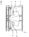
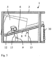
- the vibration damper assembly 1 comprises a frame 2, which can be mounted in a structure whose vibrations are to be damped or even eradicated.
- a structure is a tall, slender structure in which the ratio between height and minimum width is at least five.
- Such structures are in particular wind turbines, especially offshore wind turbines, with high steel towers, but also chimneys, antennas, skyscrapers or other offshore structures, such as transformer stations.
- the frame 2 can be rotated in a manner not shown about a vertical axis in order to follow a direction of vibration of the building can.
- the vibration damper assembly 1 has a pendulum 3, which is suspended from a pendulum joint 4 and can oscillate about a pivot point formed by the pendulum joint 4.
- the pendulum 3 is designed as a pendulum rod, which has a certain rigidity.
- a damping mass 5 is arranged at the lower end of the pendulum 3 in the direction of gravity.
- the mass of the absorber mass 5 is substantially greater than the mass of the pendulum 3, so that one can assume to a good approximation that the center of gravity of the assembly of absorber mass 5 and pendulum 3 is disposed within the absorber mass 5.
- the absorber mass 5 and thus the pendulum 3 are supported on a surface 6 against gravity.
- the surface 6 is inclined with respect to the direction of gravity.
- the surface 6 is formed as a surface of a plate 7.
- the plate 7 is arranged on a frame 8.
- the frame 8 is connected via a rotary joint 9 with the frame 2.
- the hinge 9 forms a pivot point about which the frame 8 and thus the surface 6 can be pivoted. In such a pivoting, the inclination angle of the surface 6 is changed relative to the direction of gravity.
- an adjusting device 10 is provided.
- This adjusting device may for example be designed as a spindle drive, which is arranged between the frame 8 and the frame 2.
- the absorber mass 5 is supported by a roller assembly 11 on the surface 6.
- the roller assembly 11 has a wheel 12 which can roll on the surface 6. Of course, several wheels can be provided.
- the wheel 12 is directed perpendicular to the surface 6, ie the surface 6 forms a tangent to the wheel 12. In other words, the axis of rotation of the wheel 12 is aligned parallel to the surface 6.
- the axis of rotation of the wheel 12 is also directed parallel to a plane perpendicular to the surface 6 stands and in which the pendulum 3, more precisely its central axis, is arranged.
- the wheel 12 can thus be moved virtually frictionless over the surface 6, because it only has to roll.
- the roller assembly 11 supports the arrangement of pendulum 3 and absorber mass 5 in the region of the center of mass of this arrangement. Since the inclination of the surface 6 is variable with respect to the direction of gravity, it will not be possible to ensure for all inclination angles of the surface 6 that the roller assembly 11 lies exactly below the center of mass. However, one can ensure to a good approximation that no larger tilting forces act on the roller assembly 11.
- the pivot 9 is disposed approximately below the center of mass of the arrangement of pendulum 3 and absorber mass 5, so that you do not have to apply greater forces when adjusting the inclination angle of the surface 6, which are due to a highly nonuniform mass distribution.
- the roller assembly is provided with a controllable drive device 13.
- the drive device 13 is designed as an electric drive.
- the electric drive 13 is connected in a manner not shown with a controller.
- the controller receives signals from the structure, such as vibration signals or the like. On the basis of these signals, the controller can control the drive device 13 in such a way that the absorber mass 5 executes a movement which counteracts the oscillation of the structure.
- the vibration damper arrangement 1 thereby obtains an active component, so that it is an active vibration damper arrangement 1.
- the vibration damper assembly 1 further includes an eddy current damper.
- An eddy current damper has two elements, one of which as a magnetic field generating device and one as electrical Ladder is formed.
- the magnetic field generating device may, for example, have one or more permanent magnets.
- the electrical conductor may be formed by a plate of electrically conductive material, for example of aluminum or copper or an alloy.
- the eddy current damper can also act when the drive device 13 can not work.
- a first possibility of forming the eddy current damper is to arrange the electrical conductor on the wheel 12 or another rotating position of the roller assembly 11 and to arrange the magnetic field generating device in the absorber mass adjacent to the wheel 12.
- the wheel 12 rotates during a pendulum movement of the absorber mass 5
- the above-mentioned eddy currents are generated in the electrical conductor rotating together with the wheel.
- Another possibility is to perform the plate 7 electrically conductive and to arrange a permanent magnet 14 to the absorber mass. In this arrangement, eddy currents are generated in the plate 7 when the absorber mass 5 moves over the plate 7.
- the plate 7 is flat. Accordingly, the surface 6 is formed as a flat surface.
- the Fig. 4 and 5 show the Schwingungstilgeran Aunt 1 with settings for different pendulum frequencies. By a line 15, the direction of gravity is shown.
- the adjusting device 10 can now change an angle ⁇ between the direction of gravity 15 and the frame 8. Since the surface 6 runs parallel to the frame 8, this also automatically results in a change in the angle ⁇ between the direction of gravity 15 and the surface 6.
- the assembly of the Schwingungstilgeran Aunt 1 can be done in a wind turbine in the nacelle or below the nacelle and here both outside the tower and within the tower.
- a tracking device is provided so that the effective direction of the vibration damper assembly is always oriented transversely to the wind direction.
- a mechanical coupling of the vibration damper arrangement to the nacelle can take place.
Landscapes
- Engineering & Computer Science (AREA)
- General Engineering & Computer Science (AREA)
- Architecture (AREA)
- Mechanical Engineering (AREA)
- Environmental & Geological Engineering (AREA)
- Emergency Management (AREA)
- Business, Economics & Management (AREA)
- Life Sciences & Earth Sciences (AREA)
- Sustainable Development (AREA)
- Sustainable Energy (AREA)
- Chemical & Material Sciences (AREA)
- Combustion & Propulsion (AREA)
- Civil Engineering (AREA)
- Structural Engineering (AREA)
- Vibration Prevention Devices (AREA)
Priority Applications (1)
| Application Number | Priority Date | Filing Date | Title |
|---|---|---|---|
| EP12007685.6A EP2730799B1 (fr) | 2012-11-13 | 2012-11-13 | Agencement de réduction de vibrations pour la réduction des vibrations |
Applications Claiming Priority (1)
| Application Number | Priority Date | Filing Date | Title |
|---|---|---|---|
| EP12007685.6A EP2730799B1 (fr) | 2012-11-13 | 2012-11-13 | Agencement de réduction de vibrations pour la réduction des vibrations |
Publications (2)
| Publication Number | Publication Date |
|---|---|
| EP2730799A1 true EP2730799A1 (fr) | 2014-05-14 |
| EP2730799B1 EP2730799B1 (fr) | 2019-04-17 |
Family
ID=47278057
Family Applications (1)
| Application Number | Title | Priority Date | Filing Date |
|---|---|---|---|
| EP12007685.6A Active EP2730799B1 (fr) | 2012-11-13 | 2012-11-13 | Agencement de réduction de vibrations pour la réduction des vibrations |
Country Status (1)
| Country | Link |
|---|---|
| EP (1) | EP2730799B1 (fr) |
Cited By (2)
| Publication number | Priority date | Publication date | Assignee | Title |
|---|---|---|---|---|
| CN107268819A (zh) * | 2017-06-05 | 2017-10-20 | 山东大学 | 一种多维电阻耗能减振装置 |
| WO2019201471A1 (fr) * | 2018-04-18 | 2019-10-24 | Fm Energie Gmbh & Co.Kg | Suspension cardan à amortissement pour amortisseur de vibrations |
Citations (2)
| Publication number | Priority date | Publication date | Assignee | Title |
|---|---|---|---|---|
| JPH07324518A (ja) | 1994-05-30 | 1995-12-12 | Taisei Corp | 振り子式制振装置 |
| WO2009068599A2 (fr) | 2007-11-28 | 2009-06-04 | Vestas Wind Systems A/S | Procédé pour amortir des oscillations dans une éolienne |
-
2012
- 2012-11-13 EP EP12007685.6A patent/EP2730799B1/fr active Active
Patent Citations (2)
| Publication number | Priority date | Publication date | Assignee | Title |
|---|---|---|---|---|
| JPH07324518A (ja) | 1994-05-30 | 1995-12-12 | Taisei Corp | 振り子式制振装置 |
| WO2009068599A2 (fr) | 2007-11-28 | 2009-06-04 | Vestas Wind Systems A/S | Procédé pour amortir des oscillations dans une éolienne |
Cited By (5)
| Publication number | Priority date | Publication date | Assignee | Title |
|---|---|---|---|---|
| CN107268819A (zh) * | 2017-06-05 | 2017-10-20 | 山东大学 | 一种多维电阻耗能减振装置 |
| CN107268819B (zh) * | 2017-06-05 | 2023-08-18 | 山东大学 | 一种多维电阻耗能减振装置 |
| WO2019201471A1 (fr) * | 2018-04-18 | 2019-10-24 | Fm Energie Gmbh & Co.Kg | Suspension cardan à amortissement pour amortisseur de vibrations |
| CN112219043A (zh) * | 2018-04-18 | 2021-01-12 | Fm能源有限责任两合公司 | 用于摆式减振器的阻尼万向悬挂 |
| US11732690B2 (en) | 2018-04-18 | 2023-08-22 | Fm Energie Gmbh & Co. Kg | Damping cardanic suspension for pendulum dampers |
Also Published As
| Publication number | Publication date |
|---|---|
| EP2730799B1 (fr) | 2019-04-17 |
Similar Documents
| Publication | Publication Date | Title |
|---|---|---|
| EP3665398B1 (fr) | Amortisseur de vibrations equipé d'un dispositif d'amortisseement en rotation | |
| EP2591228B1 (fr) | Éolienne et procédé de réglage de l'axe de rotation du rotor | |
| EP3402999A1 (fr) | Amortisseur d'oscillations à frein électromagnetique pour éoliennes | |
| AT516245B1 (de) | Unterbaukonstruktion zur Erhöhung der Erdbebensicherheit eines Hochspannungsbauteils | |
| EP2914844B1 (fr) | Procédé pour faire fonctionner une éolienne, éolienne et dispositif de commande pour une éolienne | |
| WO2018189245A1 (fr) | Amortissement des vibrations d'une tour de centrale éolienne | |
| DE202008017917U1 (de) | Windkraftsystem mit Heizvorrichtung | |
| EP2798202B1 (fr) | Pale de rotor et mât télescopiques, éolienne et parc éolien associés | |
| WO2001092790A1 (fr) | Dispositif de poursuite | |
| EP2730799B1 (fr) | Agencement de réduction de vibrations pour la réduction des vibrations | |
| DE102009017824B4 (de) | Übertragungsvorrichtung für eine Windturbine | |
| WO2013167652A1 (fr) | Éolienne à arbre de rotor horizontal et à mât rotatif | |
| EP2730709B1 (fr) | Agencement de réduction de vibrations | |
| EP0334241B1 (fr) | Installation de conversion d'énergie éolienne | |
| DE20021890U1 (de) | Nachführvorrichtung | |
| WO2019185196A1 (fr) | Ressort magnetique linéaire et utilisation dans des amortisseurs de vibrations | |
| EP2440783A1 (fr) | Eolienne et nacelle associée | |
| EP3575630B1 (fr) | Système d'amortissement de vibrations | |
| DE102008063808B4 (de) | Windkraftanlage | |
| WO2017162565A1 (fr) | Dispositif pivotant de retenue, de support et/ou de déplacement pour modules solaires | |
| DE19807477A1 (de) | Rotor | |
| DE102022207585A1 (de) | Bauwerksschwingungsdämpfer | |
| EP3922879A1 (fr) | Amortisseur pendulaire | |
| DE69212141T2 (de) | Vorrichtung zur ausrichtung und einstellung der position eines gegenstandes, insbesondere einer sende-/empfangsantenne für elektromagnetische wellern, in wenigstens einer von drei richtungen im raum | |
| EP3085986A1 (fr) | Dispositif d'amortisseur d'oscillations |
Legal Events
| Date | Code | Title | Description |
|---|---|---|---|
| PUAI | Public reference made under article 153(3) epc to a published international application that has entered the european phase |
Free format text: ORIGINAL CODE: 0009012 |
|
| 17P | Request for examination filed |
Effective date: 20121113 |
|
| AK | Designated contracting states |
Kind code of ref document: A1 Designated state(s): AL AT BE BG CH CY CZ DE DK EE ES FI FR GB GR HR HU IE IS IT LI LT LU LV MC MK MT NL NO PL PT RO RS SE SI SK SM TR |
|
| AX | Request for extension of the european patent |
Extension state: BA ME |
|
| R17P | Request for examination filed (corrected) |
Effective date: 20141110 |
|
| RBV | Designated contracting states (corrected) |
Designated state(s): AL AT BE BG CH CY CZ DE DK EE ES FI FR GB GR HR HU IE IS IT LI LT LU LV MC MK MT NL NO PL PT RO RS SE SI SK SM TR |
|
| REG | Reference to a national code |
Ref country code: DE Ref legal event code: R079 Ref document number: 502012014615 Country of ref document: DE Free format text: PREVIOUS MAIN CLASS: F16F0007100000 Ipc: E04B0001980000 |
|
| RIC1 | Information provided on ipc code assigned before grant |
Ipc: E04B 1/98 20060101AFI20180918BHEP Ipc: F03D 80/00 20160101ALI20180918BHEP Ipc: F16F 7/10 20060101ALI20180918BHEP |
|
| GRAP | Despatch of communication of intention to grant a patent |
Free format text: ORIGINAL CODE: EPIDOSNIGR1 |
|
| STAA | Information on the status of an ep patent application or granted ep patent |
Free format text: STATUS: GRANT OF PATENT IS INTENDED |
|
| INTG | Intention to grant announced |
Effective date: 20181105 |
|
| RIC1 | Information provided on ipc code assigned before grant |
Ipc: F03D 80/00 20160101ALI20180918BHEP Ipc: E04B 1/98 20060101AFI20180918BHEP Ipc: F16F 7/10 20060101ALI20180918BHEP |
|
| GRAS | Grant fee paid |
Free format text: ORIGINAL CODE: EPIDOSNIGR3 |
|
| GRAA | (expected) grant |
Free format text: ORIGINAL CODE: 0009210 |
|
| STAA | Information on the status of an ep patent application or granted ep patent |
Free format text: STATUS: THE PATENT HAS BEEN GRANTED |
|
| AK | Designated contracting states |
Kind code of ref document: B1 Designated state(s): AL AT BE BG CH CY CZ DE DK EE ES FI FR GB GR HR HU IE IS IT LI LT LU LV MC MK MT NL NO PL PT RO RS SE SI SK SM TR |
|
| REG | Reference to a national code |
Ref country code: GB Ref legal event code: FG4D Free format text: NOT ENGLISH |
|
| REG | Reference to a national code |
Ref country code: CH Ref legal event code: EP |
|
| REG | Reference to a national code |
Ref country code: DE Ref legal event code: R096 Ref document number: 502012014615 Country of ref document: DE |
|
| REG | Reference to a national code |
Ref country code: AT Ref legal event code: REF Ref document number: 1121708 Country of ref document: AT Kind code of ref document: T Effective date: 20190515 Ref country code: IE Ref legal event code: FG4D Free format text: LANGUAGE OF EP DOCUMENT: GERMAN |
|
| REG | Reference to a national code |
Ref country code: NL Ref legal event code: MP Effective date: 20190417 |
|
| REG | Reference to a national code |
Ref country code: LT Ref legal event code: MG4D |
|
| PG25 | Lapsed in a contracting state [announced via postgrant information from national office to epo] |
Ref country code: NL Free format text: LAPSE BECAUSE OF FAILURE TO SUBMIT A TRANSLATION OF THE DESCRIPTION OR TO PAY THE FEE WITHIN THE PRESCRIBED TIME-LIMIT Effective date: 20190417 |
|
| PG25 | Lapsed in a contracting state [announced via postgrant information from national office to epo] |
Ref country code: HR Free format text: LAPSE BECAUSE OF FAILURE TO SUBMIT A TRANSLATION OF THE DESCRIPTION OR TO PAY THE FEE WITHIN THE PRESCRIBED TIME-LIMIT Effective date: 20190417 Ref country code: LT Free format text: LAPSE BECAUSE OF FAILURE TO SUBMIT A TRANSLATION OF THE DESCRIPTION OR TO PAY THE FEE WITHIN THE PRESCRIBED TIME-LIMIT Effective date: 20190417 Ref country code: ES Free format text: LAPSE BECAUSE OF FAILURE TO SUBMIT A TRANSLATION OF THE DESCRIPTION OR TO PAY THE FEE WITHIN THE PRESCRIBED TIME-LIMIT Effective date: 20190417 Ref country code: AL Free format text: LAPSE BECAUSE OF FAILURE TO SUBMIT A TRANSLATION OF THE DESCRIPTION OR TO PAY THE FEE WITHIN THE PRESCRIBED TIME-LIMIT Effective date: 20190417 Ref country code: PT Free format text: LAPSE BECAUSE OF FAILURE TO SUBMIT A TRANSLATION OF THE DESCRIPTION OR TO PAY THE FEE WITHIN THE PRESCRIBED TIME-LIMIT Effective date: 20190817 Ref country code: FI Free format text: LAPSE BECAUSE OF FAILURE TO SUBMIT A TRANSLATION OF THE DESCRIPTION OR TO PAY THE FEE WITHIN THE PRESCRIBED TIME-LIMIT Effective date: 20190417 Ref country code: SE Free format text: LAPSE BECAUSE OF FAILURE TO SUBMIT A TRANSLATION OF THE DESCRIPTION OR TO PAY THE FEE WITHIN THE PRESCRIBED TIME-LIMIT Effective date: 20190417 Ref country code: NO Free format text: LAPSE BECAUSE OF FAILURE TO SUBMIT A TRANSLATION OF THE DESCRIPTION OR TO PAY THE FEE WITHIN THE PRESCRIBED TIME-LIMIT Effective date: 20190717 |
|
| PG25 | Lapsed in a contracting state [announced via postgrant information from national office to epo] |
Ref country code: LV Free format text: LAPSE BECAUSE OF FAILURE TO SUBMIT A TRANSLATION OF THE DESCRIPTION OR TO PAY THE FEE WITHIN THE PRESCRIBED TIME-LIMIT Effective date: 20190417 Ref country code: PL Free format text: LAPSE BECAUSE OF FAILURE TO SUBMIT A TRANSLATION OF THE DESCRIPTION OR TO PAY THE FEE WITHIN THE PRESCRIBED TIME-LIMIT Effective date: 20190417 Ref country code: GR Free format text: LAPSE BECAUSE OF FAILURE TO SUBMIT A TRANSLATION OF THE DESCRIPTION OR TO PAY THE FEE WITHIN THE PRESCRIBED TIME-LIMIT Effective date: 20190718 Ref country code: RS Free format text: LAPSE BECAUSE OF FAILURE TO SUBMIT A TRANSLATION OF THE DESCRIPTION OR TO PAY THE FEE WITHIN THE PRESCRIBED TIME-LIMIT Effective date: 20190417 Ref country code: BG Free format text: LAPSE BECAUSE OF FAILURE TO SUBMIT A TRANSLATION OF THE DESCRIPTION OR TO PAY THE FEE WITHIN THE PRESCRIBED TIME-LIMIT Effective date: 20190717 |
|
| PG25 | Lapsed in a contracting state [announced via postgrant information from national office to epo] |
Ref country code: IS Free format text: LAPSE BECAUSE OF FAILURE TO SUBMIT A TRANSLATION OF THE DESCRIPTION OR TO PAY THE FEE WITHIN THE PRESCRIBED TIME-LIMIT Effective date: 20190817 |
|
| REG | Reference to a national code |
Ref country code: DE Ref legal event code: R097 Ref document number: 502012014615 Country of ref document: DE |
|
| PG25 | Lapsed in a contracting state [announced via postgrant information from national office to epo] |
Ref country code: RO Free format text: LAPSE BECAUSE OF FAILURE TO SUBMIT A TRANSLATION OF THE DESCRIPTION OR TO PAY THE FEE WITHIN THE PRESCRIBED TIME-LIMIT Effective date: 20190417 Ref country code: CZ Free format text: LAPSE BECAUSE OF FAILURE TO SUBMIT A TRANSLATION OF THE DESCRIPTION OR TO PAY THE FEE WITHIN THE PRESCRIBED TIME-LIMIT Effective date: 20190417 Ref country code: DK Free format text: LAPSE BECAUSE OF FAILURE TO SUBMIT A TRANSLATION OF THE DESCRIPTION OR TO PAY THE FEE WITHIN THE PRESCRIBED TIME-LIMIT Effective date: 20190417 Ref country code: EE Free format text: LAPSE BECAUSE OF FAILURE TO SUBMIT A TRANSLATION OF THE DESCRIPTION OR TO PAY THE FEE WITHIN THE PRESCRIBED TIME-LIMIT Effective date: 20190417 Ref country code: SK Free format text: LAPSE BECAUSE OF FAILURE TO SUBMIT A TRANSLATION OF THE DESCRIPTION OR TO PAY THE FEE WITHIN THE PRESCRIBED TIME-LIMIT Effective date: 20190417 |
|
| PLBE | No opposition filed within time limit |
Free format text: ORIGINAL CODE: 0009261 |
|
| STAA | Information on the status of an ep patent application or granted ep patent |
Free format text: STATUS: NO OPPOSITION FILED WITHIN TIME LIMIT |
|
| PG25 | Lapsed in a contracting state [announced via postgrant information from national office to epo] |
Ref country code: IT Free format text: LAPSE BECAUSE OF FAILURE TO SUBMIT A TRANSLATION OF THE DESCRIPTION OR TO PAY THE FEE WITHIN THE PRESCRIBED TIME-LIMIT Effective date: 20190417 Ref country code: SM Free format text: LAPSE BECAUSE OF FAILURE TO SUBMIT A TRANSLATION OF THE DESCRIPTION OR TO PAY THE FEE WITHIN THE PRESCRIBED TIME-LIMIT Effective date: 20190417 |
|
| 26N | No opposition filed |
Effective date: 20200120 |
|
| PG25 | Lapsed in a contracting state [announced via postgrant information from national office to epo] |
Ref country code: TR Free format text: LAPSE BECAUSE OF FAILURE TO SUBMIT A TRANSLATION OF THE DESCRIPTION OR TO PAY THE FEE WITHIN THE PRESCRIBED TIME-LIMIT Effective date: 20190417 |
|
| PG25 | Lapsed in a contracting state [announced via postgrant information from national office to epo] |
Ref country code: SI Free format text: LAPSE BECAUSE OF FAILURE TO SUBMIT A TRANSLATION OF THE DESCRIPTION OR TO PAY THE FEE WITHIN THE PRESCRIBED TIME-LIMIT Effective date: 20190417 |
|
| REG | Reference to a national code |
Ref country code: CH Ref legal event code: PL |
|
| PG25 | Lapsed in a contracting state [announced via postgrant information from national office to epo] |
Ref country code: LI Free format text: LAPSE BECAUSE OF NON-PAYMENT OF DUE FEES Effective date: 20191130 Ref country code: LU Free format text: LAPSE BECAUSE OF NON-PAYMENT OF DUE FEES Effective date: 20191113 Ref country code: MC Free format text: LAPSE BECAUSE OF FAILURE TO SUBMIT A TRANSLATION OF THE DESCRIPTION OR TO PAY THE FEE WITHIN THE PRESCRIBED TIME-LIMIT Effective date: 20190417 Ref country code: CH Free format text: LAPSE BECAUSE OF NON-PAYMENT OF DUE FEES Effective date: 20191130 |
|
| REG | Reference to a national code |
Ref country code: BE Ref legal event code: MM Effective date: 20191130 |
|
| PG25 | Lapsed in a contracting state [announced via postgrant information from national office to epo] |
Ref country code: IE Free format text: LAPSE BECAUSE OF NON-PAYMENT OF DUE FEES Effective date: 20191113 |
|
| PG25 | Lapsed in a contracting state [announced via postgrant information from national office to epo] |
Ref country code: BE Free format text: LAPSE BECAUSE OF NON-PAYMENT OF DUE FEES Effective date: 20191130 |
|
| REG | Reference to a national code |
Ref country code: AT Ref legal event code: MM01 Ref document number: 1121708 Country of ref document: AT Kind code of ref document: T Effective date: 20191113 |
|
| PG25 | Lapsed in a contracting state [announced via postgrant information from national office to epo] |
Ref country code: AT Free format text: LAPSE BECAUSE OF NON-PAYMENT OF DUE FEES Effective date: 20191113 |
|
| PG25 | Lapsed in a contracting state [announced via postgrant information from national office to epo] |
Ref country code: CY Free format text: LAPSE BECAUSE OF FAILURE TO SUBMIT A TRANSLATION OF THE DESCRIPTION OR TO PAY THE FEE WITHIN THE PRESCRIBED TIME-LIMIT Effective date: 20190417 |
|
| PG25 | Lapsed in a contracting state [announced via postgrant information from national office to epo] |
Ref country code: HU Free format text: LAPSE BECAUSE OF FAILURE TO SUBMIT A TRANSLATION OF THE DESCRIPTION OR TO PAY THE FEE WITHIN THE PRESCRIBED TIME-LIMIT; INVALID AB INITIO Effective date: 20121113 Ref country code: MT Free format text: LAPSE BECAUSE OF FAILURE TO SUBMIT A TRANSLATION OF THE DESCRIPTION OR TO PAY THE FEE WITHIN THE PRESCRIBED TIME-LIMIT Effective date: 20190417 |
|
| PG25 | Lapsed in a contracting state [announced via postgrant information from national office to epo] |
Ref country code: MK Free format text: LAPSE BECAUSE OF FAILURE TO SUBMIT A TRANSLATION OF THE DESCRIPTION OR TO PAY THE FEE WITHIN THE PRESCRIBED TIME-LIMIT Effective date: 20190417 |
|
| P01 | Opt-out of the competence of the unified patent court (upc) registered |
Effective date: 20230524 |
|
| PGFP | Annual fee paid to national office [announced via postgrant information from national office to epo] |
Ref country code: DE Payment date: 20251125 Year of fee payment: 14 |
|
| PGFP | Annual fee paid to national office [announced via postgrant information from national office to epo] |
Ref country code: GB Payment date: 20251120 Year of fee payment: 14 |
|
| PGFP | Annual fee paid to national office [announced via postgrant information from national office to epo] |
Ref country code: FR Payment date: 20251120 Year of fee payment: 14 |