EP2730801A1 - Isolant de vibrations conçu comme un ressort pneumatique ainsi que le procédé de réglage d'un isolant de vibrations - Google Patents
Isolant de vibrations conçu comme un ressort pneumatique ainsi que le procédé de réglage d'un isolant de vibrations Download PDFInfo
- Publication number
- EP2730801A1 EP2730801A1 EP12191592.0A EP12191592A EP2730801A1 EP 2730801 A1 EP2730801 A1 EP 2730801A1 EP 12191592 A EP12191592 A EP 12191592A EP 2730801 A1 EP2730801 A1 EP 2730801A1
- Authority
- EP
- European Patent Office
- Prior art keywords
- vibration
- vibration isolator
- isolation system
- bellows
- isolator
- Prior art date
- Legal status (The legal status is an assumption and is not a legal conclusion. Google has not performed a legal analysis and makes no representation as to the accuracy of the status listed.)
- Withdrawn
Links
- 238000000034 method Methods 0.000 title claims abstract description 8
- 239000012212 insulator Substances 0.000 title description 20
- 238000002955 isolation Methods 0.000 claims abstract description 31
- 239000012530 fluid Substances 0.000 claims abstract description 7
- 230000005484 gravity Effects 0.000 claims description 14
- 230000001133 acceleration Effects 0.000 description 3
- 238000011161 development Methods 0.000 description 3
- 230000018109 developmental process Effects 0.000 description 3
- 238000001459 lithography Methods 0.000 description 3
- 239000002184 metal Substances 0.000 description 3
- 238000010276 construction Methods 0.000 description 2
- DTBDAFLSBDGPEA-UHFFFAOYSA-N 3-Methylquinoline Natural products C1=CC=CC2=CC(C)=CN=C21 DTBDAFLSBDGPEA-UHFFFAOYSA-N 0.000 description 1
- 101001042415 Cratylia mollis Mannose/glucose-specific lectin Cramoll Proteins 0.000 description 1
- 238000006243 chemical reaction Methods 0.000 description 1
- 238000006073 displacement reaction Methods 0.000 description 1
- 210000003746 feather Anatomy 0.000 description 1
- 230000001939 inductive effect Effects 0.000 description 1
- 238000004519 manufacturing process Methods 0.000 description 1
- 239000004065 semiconductor Substances 0.000 description 1
Images

Classifications
-
- G—PHYSICS
- G03—PHOTOGRAPHY; CINEMATOGRAPHY; ANALOGOUS TECHNIQUES USING WAVES OTHER THAN OPTICAL WAVES; ELECTROGRAPHY; HOLOGRAPHY
- G03F—PHOTOMECHANICAL PRODUCTION OF TEXTURED OR PATTERNED SURFACES, e.g. FOR PRINTING, FOR PROCESSING OF SEMICONDUCTOR DEVICES; MATERIALS THEREFOR; ORIGINALS THEREFOR; APPARATUS SPECIALLY ADAPTED THEREFOR
- G03F7/00—Photomechanical, e.g. photolithographic, production of textured or patterned surfaces, e.g. printing surfaces; Materials therefor, e.g. comprising photoresists; Apparatus specially adapted therefor
- G03F7/70—Microphotolithographic exposure; Apparatus therefor
- G03F7/708—Construction of apparatus, e.g. environment aspects, hygiene aspects or materials
- G03F7/70858—Environment aspects, e.g. pressure of beam-path gas, temperature
- G03F7/709—Vibration, e.g. vibration detection, compensation, suppression or isolation
-
- F—MECHANICAL ENGINEERING; LIGHTING; HEATING; WEAPONS; BLASTING
- F16—ENGINEERING ELEMENTS AND UNITS; GENERAL MEASURES FOR PRODUCING AND MAINTAINING EFFECTIVE FUNCTIONING OF MACHINES OR INSTALLATIONS; THERMAL INSULATION IN GENERAL
- F16F—SPRINGS; SHOCK-ABSORBERS; MEANS FOR DAMPING VIBRATION
- F16F15/00—Suppression of vibrations in systems; Means or arrangements for avoiding or reducing out-of-balance forces, e.g. due to motion
- F16F15/02—Suppression of vibrations of non-rotating, e.g. reciprocating systems; Suppression of vibrations of rotating systems by use of members not moving with the rotating systems
- F16F15/023—Suppression of vibrations of non-rotating, e.g. reciprocating systems; Suppression of vibrations of rotating systems by use of members not moving with the rotating systems using fluid means
- F16F15/027—Suppression of vibrations of non-rotating, e.g. reciprocating systems; Suppression of vibrations of rotating systems by use of members not moving with the rotating systems using fluid means comprising control arrangements
-
- F—MECHANICAL ENGINEERING; LIGHTING; HEATING; WEAPONS; BLASTING
- F16—ENGINEERING ELEMENTS AND UNITS; GENERAL MEASURES FOR PRODUCING AND MAINTAINING EFFECTIVE FUNCTIONING OF MACHINES OR INSTALLATIONS; THERMAL INSULATION IN GENERAL
- F16F—SPRINGS; SHOCK-ABSORBERS; MEANS FOR DAMPING VIBRATION
- F16F9/00—Springs, vibration-dampers, shock-absorbers, or similarly-constructed movement-dampers using a fluid or the equivalent as damping medium
- F16F9/02—Springs, vibration-dampers, shock-absorbers, or similarly-constructed movement-dampers using a fluid or the equivalent as damping medium using gas only or vacuum
- F16F9/04—Springs, vibration-dampers, shock-absorbers, or similarly-constructed movement-dampers using a fluid or the equivalent as damping medium using gas only or vacuum in a chamber with a flexible wall
Definitions
- the invention relates to a vibration isolator, which is designed as a pneumatic spring and which is used in particular for vibration isolation systems, as used in lithography. Furthermore, the invention relates to a method for tuning a pneumatic vibration isolator.
- Vibration isolation systems as used in particular in lithography in the manufacture of semiconductor devices, are known.
- Such a vibration isolation system usually comprises a vibration-isolated construction, which is designed in particular as a table, which rests on at least three vibration isolators.
- pneumatic springs are known, which are used as a vibration isolator.
- Such a vibration isolator is for example in the document EP 2 071 211 A2 (Integrated Dynamics Engineering GmbH).
- Such a designed as a pneumatic spring vibration isolator may in particular include a bellows.
- the vibration isolation serving volume of air is closed so that it can be used in particular in a vacuum.
- vibration isolation systems comprise substantially identically designed vibration isolators, that is, the insulators are designed in particular for carrying equal-sized loads.
- the center of gravity of the isolated load is spaced from the geometric center between the insulators, which results in the force not being distributed evenly across the vibration isolators.
- generic vibration isolation systems in lithography are usually designed as active vibration isolation systems with a control loop and comprise sensors with which at least vibrations of the vibration-isolated mounted load are measured and by means of which the position of the table is determined directly or indirectly at the location of the respective insulator.
- the pressure in the working chamber of the isolator can now be adapted in the case of a vibration isolator designed as a pneumatic spring in order to compensate for different weight forces on the insulators.
- the invention is based on the object to reduce the mentioned disadvantages of the prior art.
- the object of the invention is already achieved by a vibration isolator, which is designed as a pneumatic spring, and by a method for tuning a vibration isolation system according to one of the independent claims.
- the invention relates to a trained as a pneumatic spring vibration isolator.
- the invention relates to a basic structure ago a vibration isolator, as this in the document EP 2 071 211 A2 is described.
- Such a vibration isolator comprises a substantially fluid-tight working space and operates as a pneumatic spring.
- the working space is at least partially formed as a bellows, in particular as a metal bellows.
- the vibration isolator can furthermore detect sensors, in particular for detecting vibrations and position changes of the vibration-isolated load.
- the vibration isolator is effective in both the vertical and horizontal directions.
- the stiffness in the horizontal and in the vertical direction which depends at least among other things on the resonant frequency of the insulator.
- a vibration isolator in which the piston area of the working space and / or the volume of the pneumatic spring are variable.
- piston area and volume of the working space are variable.
- the piston surface is understood to mean the surface which is effective at applied pressure to generate a force.
- the diameter of the bellows usually corresponds to the effective piston area, because in adjacent volumes forces generated by the pressure otherwise cancel each other out.
- the vibration isolator has a replaceable module with a bellows.
- an exchangeable housing part is provided in one embodiment of the invention, which provides an additional volume, by means of the dimensioning of the volume of the working space can be increased or reduced in a very simple manner.
- the natural frequency of a designed as a pneumatic spring vibration isolator is essentially determined by the root of the quotient of the piston surface and the volume, changes in a change in the piston area, such as by replacing the bellows, and the natural frequency.
- the additional volume is preferably arranged easily accessible below a bottom plate of the vibration isolator.
- the vibration isolator comprises a pivot joint spaced apart from the bellows in the vertical direction.
- Metal bellows and pivot bearings form such an articulated pendulum.
- the horizontal stiffness of the insulator is determined by the mechanical components, in particular by the metal bellows.
- the hinge In combination with a spaced hinge, the hinge provides negative horizontal stiffness, allowing for low horizontal stiffness.
- a spring can be added for the application of an additional horizontal rigidity.
- a spring may be configured in particular as a leaf spring.
- a position sensor is arranged in the pneumatic spring, with which in particular vibrations of the isolated stored load are detected.
- a position sensor is therefore not just a Sensor understood that detects the absolute position of the vibration-isolated mounted load, but any sensor that detects a position-related variable, such as acceleration or speed.
- the sensors can be designed in particular as inductive sensors, capacitive sensors or piezo sensors.
- the vibration isolator is preferably constructed such that the pneumatic spring has a lower part, which is connected via a bellows with the upper part and wherein the upper part, preferably via a rotary joint, is connected to the load to be insulated.
- the invention further relates to a vibration isolation system comprising a plurality of the above-described vibration isolators.
- At least two of the vibration isolators have a different volume of fluid and / or a different piston area, but otherwise are of essentially identical construction and have in particular identically designed housing components and have the same external dimensions.
- the center of gravity of a vibration-isolated load can be spaced from the geometric center of the vibration isolators.
- Differences in the resulting force distribution on the insulators are at least partially compensated by a different piston area.
- the invention further relates to a method for tuning a vibration isolation system, in particular a vibration isolation system, as described above.
- the position of the center of gravity of a load to be isolated is determined.
- An optimized piston surface is understood to mean that the piston surfaces present in the vibration isolation system differ in such a way that a larger piston surface is used at a location with a higher weight force.
- the volume of the vibration isolator designed as a pneumatic spring is now also changed in order to at least partially compensate for a natural frequency change due to the change in the piston area.
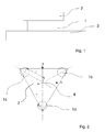
- Fig. 1 schematically shows the basic principle of a vibration isolation system.
- the vibration isolation system comprises a load 2 to be insulated, which is mounted on the base 3 via vibration isolators 1. It is understood that in practice it is a complex system with a plurality of components, which are not shown.
- the vibration isolators 1 are designed as pneumatic springs and have a control loop such that via sensors (not shown) vibrations or changes in position are detected and the pressure in the pneumatic spring is controlled via a control loop.
- Fig. 2 shows a further schematic view of a vibration isolation system, which is designed as a tripod.
- the load 2 to be insulated is mounted on the vibration isolators 1a to 1c designed as pneumatic springs.
- the vibration isolators 1a to 1c form the basis for the vibration-isolated load 2, wherein the lines of action of the insulators meet in the geometric center 4.
- the three insulators 1 a to 1 c are each located at a distance L from the geometric center, the directions x and y are along the main extension direction of the load to be isolated second
- Equation (II) says nothing other than that the sum of the forces of all insulators in the vertical direction should be equal to the weight of the mass to be isolated (g is the gravitational acceleration). Equation (I) also requires that the torques of the forces acting on the insulators, which act on the center of gravity S, must be equal to zero in the sum.
- F 2 1 3 ⁇ mg ⁇ 3 ⁇ S x + L + S y L .
- F 3 - 1 3 ⁇ mg ⁇ 3 ⁇ S x - L - S y L compared to the load case in the geometric center
- ⁇ ⁇ F 2 1 + 3 ⁇ S x + S y L .
- ⁇ ⁇ F 3 1 + S y - 3 ⁇ S x L
- the force change thus runs linearly with the pressure, but quadratically with the diameter of the piston surface.
- V 1 4 ⁇ nAg ⁇ 2
- the volume can be adjusted accordingly. Since this is inversely proportional, so an increase by 17% is necessary to get back to the original natural frequency.
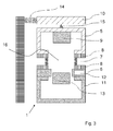
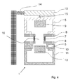
- Fig. 3 and Fig. 4 show a schematic representation of a trained as a pneumatic spring vibration isolator in a sectional view.
- the vibration isolator 1 comprises an upper part 5 and a lower part 6.
- a bellows 7 is arranged between the upper part 5 and the lower part 6.
- the housing is otherwise closed except for the fluid supply (not shown) and the pressure prevailing in the working space of the vibration isolator provides vibration isolation in both the horizontal and vertical directions.
- the lower part 6 comprises a passage 12 for cables.
- At least one sensor 9 is arranged, which detects vibrations of the isolated stored load.
- a rotary joint 15 is arranged between a head piece 10 and the upper part 5.
- Bellows 7 and pivot 15 thus form an articulated pendulum and by the rotary joint 15, a negative stiffness in the horizontal direction is provided, which compensates the positive stiffness of the mechanical components, in particular of the bellows 7.
- a spring 14 can be provided on the head piece 10 to apply an additional positive stiffness in the horizontal direction.
- the spring 14 may be formed in particular as a leaf spring (not shown), in particular as a leaf spring whose spring force is adjustable.
- the vibration isolator shown here further comprises means for applying a negative rigidity 13 in the vertical direction. This should also be reduced in the vertical direction, the positive stiffness due to the mechanical components.
- a magnetic spring device For applying a negative rigidity, in particular a magnetic spring device can be used. Such is particularly in the document EP 1 359 341 B1 (Integrated Dynamics Engineering GmbH).
- the effective piston area is determined in the case of the vibration isolator shown here essentially by the diameter of the bellows 7.
- the bellows 7 comprises on both sides flanges 8, which are designed to be unscrewable and by means of which the bellows with the upper part 5 and the lower part 6 is connected.
- these flanges are accessible from the outside in the assembled state, so that no further components must be dismantled.
- the vibration isolator below the lower part 6 comprises an exchangeable additional volume 11, which is also accessible from the outside and can be changed by the exchange in a very simple manner, the volume of the working space of the vibration isolator to change the natural frequency of the vibration isolator 1.
- a vibration isolator could be provided, which allows a very simple way to adapt to a different load.
- the position of the center of gravity of a load to be isolated is determined.
- At least one bellows of an isolator of the vibration isolation system is exchanged to at least partially compensate for the unequal load distribution.
- the volume of the working space changes.
- the associated natural frequency change is determined and replaced on this basis, the additional volume of the working space to compensate for the natural frequency change at least partially.
Landscapes
- Engineering & Computer Science (AREA)
- General Engineering & Computer Science (AREA)
- Health & Medical Sciences (AREA)
- Mechanical Engineering (AREA)
- Physics & Mathematics (AREA)
- Epidemiology (AREA)
- Environmental & Geological Engineering (AREA)
- Public Health (AREA)
- Toxicology (AREA)
- General Physics & Mathematics (AREA)
- Acoustics & Sound (AREA)
- Aviation & Aerospace Engineering (AREA)
- Atmospheric Sciences (AREA)
- Life Sciences & Earth Sciences (AREA)
- Vibration Prevention Devices (AREA)
Priority Applications (1)
| Application Number | Priority Date | Filing Date | Title |
|---|---|---|---|
| EP12191592.0A EP2730801A1 (fr) | 2012-11-07 | 2012-11-07 | Isolant de vibrations conçu comme un ressort pneumatique ainsi que le procédé de réglage d'un isolant de vibrations |
Applications Claiming Priority (1)
| Application Number | Priority Date | Filing Date | Title |
|---|---|---|---|
| EP12191592.0A EP2730801A1 (fr) | 2012-11-07 | 2012-11-07 | Isolant de vibrations conçu comme un ressort pneumatique ainsi que le procédé de réglage d'un isolant de vibrations |
Publications (1)
| Publication Number | Publication Date |
|---|---|
| EP2730801A1 true EP2730801A1 (fr) | 2014-05-14 |
Family
ID=47146239
Family Applications (1)
| Application Number | Title | Priority Date | Filing Date |
|---|---|---|---|
| EP12191592.0A Withdrawn EP2730801A1 (fr) | 2012-11-07 | 2012-11-07 | Isolant de vibrations conçu comme un ressort pneumatique ainsi que le procédé de réglage d'un isolant de vibrations |
Country Status (1)
| Country | Link |
|---|---|
| EP (1) | EP2730801A1 (fr) |
Citations (5)
| Publication number | Priority date | Publication date | Assignee | Title |
|---|---|---|---|---|
| US6126152A (en) * | 1997-03-10 | 2000-10-03 | Synergy Services, Ltd. | Variable response pneumatic support |
| US6408767B1 (en) * | 2000-03-01 | 2002-06-25 | Nikon Corporation | Low stiffness suspension for a stage |
| EP1359341B1 (fr) | 2002-05-03 | 2006-02-08 | Integrated Dynamics Engineering GmbH | Dispositif de ressort magnétique à rigidité négative |
| EP2034210A2 (fr) * | 2007-09-06 | 2009-03-11 | BFS Diversified Products, LLC. | Piston modulaire à ressort pneumatique |
| EP2071211A2 (fr) | 2007-12-10 | 2009-06-17 | Integrated Dynamics Engineering GmbH | Isolant de vibrations destiné à l'utilisation sous vide |
-
2012
- 2012-11-07 EP EP12191592.0A patent/EP2730801A1/fr not_active Withdrawn
Patent Citations (5)
| Publication number | Priority date | Publication date | Assignee | Title |
|---|---|---|---|---|
| US6126152A (en) * | 1997-03-10 | 2000-10-03 | Synergy Services, Ltd. | Variable response pneumatic support |
| US6408767B1 (en) * | 2000-03-01 | 2002-06-25 | Nikon Corporation | Low stiffness suspension for a stage |
| EP1359341B1 (fr) | 2002-05-03 | 2006-02-08 | Integrated Dynamics Engineering GmbH | Dispositif de ressort magnétique à rigidité négative |
| EP2034210A2 (fr) * | 2007-09-06 | 2009-03-11 | BFS Diversified Products, LLC. | Piston modulaire à ressort pneumatique |
| EP2071211A2 (fr) | 2007-12-10 | 2009-06-17 | Integrated Dynamics Engineering GmbH | Isolant de vibrations destiné à l'utilisation sous vide |
Similar Documents
| Publication | Publication Date | Title |
|---|---|---|
| EP3052329B1 (fr) | Siège de véhicule ou cabine de véhicule doté(e) d'un dispositif de suspension et véhicule utilitaire | |
| EP3052330B1 (fr) | Siège de véhicule ou cabine de véhicule doté(e) d'un dispositif de suspension et véhicule utilitaire | |
| EP2759736B1 (fr) | Isolateur de vibrations comprenant un ressort cylindrique | |
| DE102012220036B4 (de) | Bewegungssystem, das ausgestaltet ist, um eine nutzlast inmehrere richtungen zu bewegen | |
| EP0367949B1 (fr) | Système de suspension pour véhicules | |
| EP3260732B1 (fr) | Actionneur pneumatique et procede de fonctionnement d'un systeme actif d'isolation d'oscillations | |
| WO2002055813A1 (fr) | Manipulateur de grande dimension avec amortissement de vibrations | |
| DE2029814A1 (fr) | ||
| EP3037608A1 (fr) | Système de montage pour installations industrielles modulaires | |
| EP3181944A1 (fr) | Isolateur de vibrations doté d'un ressort pneumatique vertical | |
| DE102013010595A1 (de) | Flüssigkeitssäulendämpfungssystem | |
| DE10000771A1 (de) | Vorrichtung und Verfahren zur Lageregelung für Arbeitseinrichtungen mobiler Arbeitsmaschinen | |
| DE10346811B4 (de) | Kraftmeßvorrichtung | |
| EP1865220A1 (fr) | Système actif d'isolation de vibrations avec efficacité améliorée contre les vibrations sismiques | |
| EP3698067A1 (fr) | Amortisseur de vibration, en particulier pour une armoire de distribution | |
| WO2007071101A1 (fr) | Element de construction pneumatique | |
| EP2730801A1 (fr) | Isolant de vibrations conçu comme un ressort pneumatique ainsi que le procédé de réglage d'un isolant de vibrations | |
| DE102013219279A1 (de) | Lastbewegungsdämpfer und Hebevorrichtung für hängende Lasten | |
| EP3334953A1 (fr) | Dispositif et procédé d'accouplement mécanique d'au moins un corps monté de manière oscillante et son utilisation en tant qu'élément d'amortissement réglable de manière variable | |
| EP0371322A2 (fr) | Dispositif de mesure de l'état de surfaces | |
| DE102019114086A1 (de) | Steuer- und/oder Regelsystem für ein landwirtschaftliches Gerät | |
| DE10249647B4 (de) | Pneumatischer Schwingungsisolator | |
| DE951685C (de) | Vorrichtung zum Ausgleich einer innerhalb eines bestimmten Bereiches senkrecht beweglichen Last | |
| EP2772661B1 (fr) | Procédé de dimensionnement d'un isolateur de vibrations | |
| DE102022101722A1 (de) | Schwingungsisolator |
Legal Events
| Date | Code | Title | Description |
|---|---|---|---|
| PUAI | Public reference made under article 153(3) epc to a published international application that has entered the european phase |
Free format text: ORIGINAL CODE: 0009012 |
|
| 17P | Request for examination filed |
Effective date: 20121107 |
|
| AK | Designated contracting states |
Kind code of ref document: A1 Designated state(s): AL AT BE BG CH CY CZ DE DK EE ES FI FR GB GR HR HU IE IS IT LI LT LU LV MC MK MT NL NO PL PT RO RS SE SI SK SM TR |
|
| AX | Request for extension of the european patent |
Extension state: BA ME |
|
| R17P | Request for examination filed (corrected) |
Effective date: 20140605 |
|
| RBV | Designated contracting states (corrected) |
Designated state(s): AL AT BE BG CH CY CZ DE DK EE ES FI FR GB GR HR HU IE IS IT LI LT LU LV MC MK MT NL NO PL PT RO RS SE SI SK SM TR |
|
| STAA | Information on the status of an ep patent application or granted ep patent |
Free format text: STATUS: THE APPLICATION HAS BEEN WITHDRAWN |
|
| 18W | Application withdrawn |
Effective date: 20171129 |