EP2730864A2 - Réfrigérateur doté d'une machine à glaçons avec moule à glaçons flexible et procédé de récolte de glace - Google Patents
Réfrigérateur doté d'une machine à glaçons avec moule à glaçons flexible et procédé de récolte de glace Download PDFInfo
- Publication number
- EP2730864A2 EP2730864A2 EP13173613.4A EP13173613A EP2730864A2 EP 2730864 A2 EP2730864 A2 EP 2730864A2 EP 13173613 A EP13173613 A EP 13173613A EP 2730864 A2 EP2730864 A2 EP 2730864A2
- Authority
- EP
- European Patent Office
- Prior art keywords
- ice
- cubes
- mold
- rotatable member
- upward facing
- Prior art date
- Legal status (The legal status is an assumption and is not a legal conclusion. Google has not performed a legal analysis and makes no representation as to the accuracy of the status listed.)
- Withdrawn
Links
- 238000003306 harvesting Methods 0.000 title claims description 28
- 238000000034 method Methods 0.000 title claims description 13
- 229910052782 aluminium Inorganic materials 0.000 claims abstract description 7
- XAGFODPZIPBFFR-UHFFFAOYSA-N aluminium Chemical compound [Al] XAGFODPZIPBFFR-UHFFFAOYSA-N 0.000 claims abstract description 7
- XLYOFNOQVPJJNP-UHFFFAOYSA-N water Substances O XLYOFNOQVPJJNP-UHFFFAOYSA-N 0.000 claims description 25
- 238000004519 manufacturing process Methods 0.000 claims description 2
- 239000000463 material Substances 0.000 abstract description 2
- 230000007246 mechanism Effects 0.000 description 5
- 238000003860 storage Methods 0.000 description 4
- 230000009471 action Effects 0.000 description 3
- 239000002826 coolant Substances 0.000 description 2
- 239000007788 liquid Substances 0.000 description 2
- 238000002844 melting Methods 0.000 description 2
- 230000008018 melting Effects 0.000 description 2
- 239000003507 refrigerant Substances 0.000 description 2
- 102000002322 Egg Proteins Human genes 0.000 description 1
- 108010000912 Egg Proteins Proteins 0.000 description 1
- 238000007792 addition Methods 0.000 description 1
- 230000015572 biosynthetic process Effects 0.000 description 1
- 230000000903 blocking effect Effects 0.000 description 1
- 238000004891 communication Methods 0.000 description 1
- 210000003278 egg shell Anatomy 0.000 description 1
- 239000002783 friction material Substances 0.000 description 1
- 230000005484 gravity Effects 0.000 description 1
- 238000013340 harvest operation Methods 0.000 description 1
- 238000012787 harvest procedure Methods 0.000 description 1
- 229910052751 metal Inorganic materials 0.000 description 1
- 239000002184 metal Substances 0.000 description 1
- 238000012986 modification Methods 0.000 description 1
- 230000004048 modification Effects 0.000 description 1
- 238000003825 pressing Methods 0.000 description 1
- 230000002265 prevention Effects 0.000 description 1
- 230000008569 process Effects 0.000 description 1
- 239000007787 solid Substances 0.000 description 1
- 238000006467 substitution reaction Methods 0.000 description 1
Images



Classifications
-
- F—MECHANICAL ENGINEERING; LIGHTING; HEATING; WEAPONS; BLASTING
- F25—REFRIGERATION OR COOLING; COMBINED HEATING AND REFRIGERATION SYSTEMS; HEAT PUMP SYSTEMS; MANUFACTURE OR STORAGE OF ICE; LIQUEFACTION SOLIDIFICATION OF GASES
- F25C—PRODUCING, WORKING OR HANDLING ICE
- F25C5/00—Working or handling ice
- F25C5/02—Apparatus for disintegrating, removing or harvesting ice
- F25C5/04—Apparatus for disintegrating, removing or harvesting ice without the use of saws
-
- F—MECHANICAL ENGINEERING; LIGHTING; HEATING; WEAPONS; BLASTING
- F25—REFRIGERATION OR COOLING; COMBINED HEATING AND REFRIGERATION SYSTEMS; HEAT PUMP SYSTEMS; MANUFACTURE OR STORAGE OF ICE; LIQUEFACTION SOLIDIFICATION OF GASES
- F25C—PRODUCING, WORKING OR HANDLING ICE
- F25C1/00—Producing ice
- F25C1/04—Producing ice by using stationary moulds
-
- F—MECHANICAL ENGINEERING; LIGHTING; HEATING; WEAPONS; BLASTING
- F25—REFRIGERATION OR COOLING; COMBINED HEATING AND REFRIGERATION SYSTEMS; HEAT PUMP SYSTEMS; MANUFACTURE OR STORAGE OF ICE; LIQUEFACTION SOLIDIFICATION OF GASES
- F25C—PRODUCING, WORKING OR HANDLING ICE
- F25C5/00—Working or handling ice
- F25C5/02—Apparatus for disintegrating, removing or harvesting ice
- F25C5/04—Apparatus for disintegrating, removing or harvesting ice without the use of saws
- F25C5/06—Apparatus for disintegrating, removing or harvesting ice without the use of saws by deforming bodies with which the ice is in contact, e.g. using inflatable members
-
- F—MECHANICAL ENGINEERING; LIGHTING; HEATING; WEAPONS; BLASTING
- F25—REFRIGERATION OR COOLING; COMBINED HEATING AND REFRIGERATION SYSTEMS; HEAT PUMP SYSTEMS; MANUFACTURE OR STORAGE OF ICE; LIQUEFACTION SOLIDIFICATION OF GASES
- F25C—PRODUCING, WORKING OR HANDLING ICE
- F25C5/00—Working or handling ice
- F25C5/20—Distributing ice
- F25C5/22—Distributing ice particularly adapted for household refrigerators
-
- F—MECHANICAL ENGINEERING; LIGHTING; HEATING; WEAPONS; BLASTING
- F25—REFRIGERATION OR COOLING; COMBINED HEATING AND REFRIGERATION SYSTEMS; HEAT PUMP SYSTEMS; MANUFACTURE OR STORAGE OF ICE; LIQUEFACTION SOLIDIFICATION OF GASES
- F25C—PRODUCING, WORKING OR HANDLING ICE
- F25C2305/00—Special arrangements or features for working or handling ice
- F25C2305/024—Rotating rake
Definitions
- the present invention relates generally to household refrigerators, and more particularly to refrigerators that include an icemaker with a mold for forming and automatically harvesting ice.
- an automatic ice maker within a household refrigerator.
- an ice maker includes an ice mold with a plurality of open compartments.
- a complete ice making cycle includes filling the ice mold compartments with water, removing heat from the water to form ice pieces, and harvesting the ice pieces from the mold. It is desirable to reduce the overall time of the ice making cycle in order to maximize the amount of ice that can be produced by an ice maker.
- the ice mold acts as a conduit for removing heat from the water. Therefore, it is desirable to form the mold from a material that conducts heat well in order to quickly remove heat from the water.
- the most common mechanism for removing heat from an ice mold, and thereby the water within the mold, is to provide cold air from an evaporator to the ice mold.
- the ice mold may be chilled by direct contact with an evaporator or other conduit of a working refrigerant.
- a secondary coolant may be provided to the ice mold to remove heat. It is also known to use thermoelectric devices or the like to cool the ice mold.
- heat is provided to the ice mold to break the adhesion between the mold and ice.
- the greater the thermal mass of the mold the greater the amount of energy, and therefore time, is required to sufficiently heat the mold and thereby melt the ice pieces at the interfaces between the mold and the ice pieces.
- a variety of mechanisms can be used to complete the harvest.
- a rake, or similar element is passed through the individual ice compartments to eject the ice pieces from the mold. Typically this is accomplished by rotating the rake while the ice mold remains stationary.
- the ice mold itself is rotated to an inverted position, and the ice pieces are allowed to drop out of the mold under the force of gravity.
- a twisting force may be applied to the inverted mold to help break the adhesions and urge the ice out of the mold. Commonly, this twisting action is accomplished by including a stop at one end of the ice mold to prevent that end from rotating as far as the other end during the inverting process.
- the present invention provides an improved ice mold and method that reduces the time needed to make and harvest ice cubes.
- the present invention improves the harvest process by providing a thin flexible mold that remains generally stationary during the harvesting process.
- a rotatable rake includes a cam that contacts a top surface of the mold, thereby flexing the mold and causing adhesion between the ice mold and the ice cubes to be broken, such that the rake can remove the ice cubes from the mold.
- the present invention is directed to a refrigerator that has a cabinet and a door for providing access to the cabinet.
- An icemaker is mounted within the cabinet or on the door.
- the icemaker includes an ice mold with a plurality of ice cube forming mold sections with upward facing openings.
- the ice mold also includes an upward facing surface.
- a supply of water is provided to the ice cube forming mold sections.
- a rotatable member rotates about an axis that is spaced apart from the upward facing surface by a first distance.
- the rotatable member includes fingers in alignment with the ice cube forming mold sections such that rotation of the rotatable member about the axis causes the fingers to contact and thereby dislodge and harvest ice cubes from the ice cube forming mold sections.
- a cam projection extends from the rotatable member to a second distance from the axis, the second distance being greater than the first distance. Whereby rotation of the rotatable member causes the cam projection to contact the upward facing surface of the ice mold to thereby flex the ice mold and at least partially break a bond between the ice cubes and the ice cube forming mold sections to facilitate harvesting of the ice cubes by the fingers.
- the ice mold may be formed from a single piece of stamped aluminum.
- a second cam projection may from the rotatable member to a third distance from the axis, the third distance being greater than the first distance.
- the third distance may be equal to the second distance.
- the cam projection may have a low friction surface such that the low friction surface slides freely across the upward facing surface of the ice mold.
- the ice cube forming mold sections may be concavely curved from front-to-back and from side-to-side.
- the upward facing surface may have a front edge and rear edge such that when the rotatable member is rotated in a first direction to dislodge and harvest ice cubes, the fingers move generally in a direction toward the rear edge as they contact the ice cubes within the ice cube forming mold sections.
- the refrigerator may further include an ice cube deflector positioned generally above the upward facing surface proximate the rear edge of the upward facing surface such that ice cubes dislodged from the ice cube forming mold sections are guided over the mold towards the front edge by the deflector as the rotatable member rotates with the fingers in contact with the dislodged cubes.
- the cube deflector may have a plurality of concavely curved inner surfaces that generally match a curvature of the ice cubes.
- the cube deflector may include separator walls between the curved inner surfaces to break ice bridges between the cubes.
- the upward facing surface may have a front edge and a rear edge such that when the rotatable member is rotated in a first direction to dislodge and harvest ice cubes, the fingers move in a direction toward the front edge as they contact ice cubes within the ice cube forming mold sections.
- An ice cube deflector may be positioned spaced apart from and above the upward facing surface between the front edge and the axis such that ice cubes dislodged from the ice cube forming mold sections are deflected downwardly over the front edge.
- the present invention is directed to a method of making and harvesting ice cubes that includes providing a refrigerator with an ice maker having an ice mold.
- the ice mold includes a plurality of ice cube forming mold sections with upward facing openings.
- the ice mold further includes an upward facing surface.
- a rotatable member including fingers in alignment with the ice cube forming mold sections is provided.
- the rotatable member also has a cam projection. Water is provided to the ice cube forming mold sections, and heat is removed from the water to form ice cubes in the ice cube forming mold sections.
- An adhesion between the ice cubes and the ice cube forming mold sections is broken by rotating the rotatable member to bring the cam projection into contact with the upward facing surface of the ice mold to thereby flex the ice mold.
- the ice cubes are removed from the ice cube forming mold sections by continuing to rotate the rotatable member such that fingers pass through the ice cube forming mold sections.
- the rotatable member may have a second cam projection.
- the step of breaking the adhesion may include bringing the second cam projection into contact with the upward facing surface.
- the ice mold may be formed from a single piece of stamped aluminum.
- the cam projection may have a low friction surface such that the low friction surface slides freely across the upward facing surface of the ice mold.
- the ice mold sections are concavely curved from front-to-back and from side-to-side.
- the upward facing surface may have a front edge and rear edge such that rotating the rotatable member in a first direction moves the fingers generally toward the rear edge as they contact the ice cubes within the ice cube forming mold sections.
- An ice cube deflector is positioned generally above the upward facing surface proximate to the rear edge of the upward facing surface such that ice cubes dislodged from the ice cube forming mold sections are guided above the mold towards the front edge by the ice cube deflector as the rotatable member rotates in the first direction with the fingers in contact with the dislodged cubes.
- the cube deflector may have a plurality of concavely curved inner surfaces that generally match a curvature of the ice cubes.
- the cube deflector may have separator walls between the curved inner surfaces to break ice bridges between the cubes.
- the upward facing surface may have a front edge and a rear edge.
- the method may further include rotating the rotatable member in a first direction to dislodge and harvest ice cubes by moving the fingers toward the front edge as the fingers contact ice cubes until the ice cubes are deflected downwardly over the front edge by an ice cube deflector spaced apart from and above the upward facing surface between the front edge and the axis.
- the rotatable member may be rotated in a second direction opposite from the first direction until the fingers have passed completely through the ice cube forming mold sections moving in the second direction before again providing water to the ice cube forming mold sections.
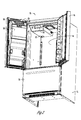
- a bottom mount refrigerator 10 is shown in Figures 1 and 2 .
- the refrigerator 10 includes a cabinet 11 that encloses fresh food compartment 12 and a freezer compartment below the fresh food compartment 12. Doors 16 are provided for the refrigerator compartment or fresh food compartment 12 and a door 18 is provided for the freezer compartment.
- the freezer door 18 may take the form of a drawer, as shown in the drawings, or may be a conventional hinged design.
- One of the fresh food compartment doors 16 includes an ice dispenser 20, which may also include a water dispenser. While the embodiment shown is a bottom mount refrigerator 10 with the freezer compartment below the fresh food compartment 12, it should be appreciated that the present invention is not so limited and can be used beneficially in side-by-side refrigerators as well as top-mount refrigerators with the freezer compartment above the fresh food compartment.
- An icemaking compartment 22 is provided in the fresh food compartment 12.
- the icemaking compartment 22 is shown to be in one of the upper corners of the fresh food, compartment 12, but other locations are also within the scope of this invention.
- the icemaking compartment could be provided on the freezer door 18 or on a fresh food compartment door 16.
- the icemaking compartment 22 is insulated to prevent the cold air of the icemaking compartment 22 from passing into the refrigerator compartment.
- An opening 24 is provided at the front of the icemaking compartment 22 that aligns with chute 19 which leads to an ice storage compartment 26 on one of the doors 16.
- An ice bin (not shown) is provided within the ice storage compartment 26 to store the ice until it is dispensed.
- the present invention is not limited to such an arrangement and would be suitable for use in a variety of arrangements, including, without limitation, locating the icemaker in the freezer compartment, or on any of the freezer or fresh food doors.
- an ice making module 28 is provided within the ice making compartment 22.
- the ice making module 28 includes an ice mold 30, a cover 32, an ice rake 34, a deflector 36, and a stripper 37. While not shown in the drawings, the ice mold 30 is provided in close proximity to a supply of water that can be provided to the ice mold 30 to form ice cubes. Also not shown is an ice bin that is provided generally below and in communication with the ice mold 30 to store the ice cubes after they are harvested until the cubes are dispensed. The ice bin is provided in the ice storage compartment 26 in the embodiment shown, but may be provided within the ice making compartment or freezer compartment if desired.
- FIGS 5a-d show a partial cross-section view of an ice mold 30 according to one embodiment of the present invention.
- the ice mold 30 is formed from a single stamped piece of thin aluminum.
- the ice mold 30 includes a plurality of mold sections 46 that extend downwardly below an upper surface 42 of the ice mold 30.
- the ice mold sections 46 are concavely curved front-to-back and side-to-side.
- the overall shape of the ice mold sections 46 is similar to a section of a symmetrical egg shell.
- the ice mold sections 46 serve as ice cube forming compartments when filled with water.
- a heater such as a wire heater 48, may be provided around the periphery, or preferably along the bottom surface, of the ice mold 30. Because the stamped aluminum is thin, there is very little thermal mass that needs to be heated to raise the temperature of the mold 30 when the heater 48 is activated. Alternatively, the present invention may eliminate the need for a heater.
- the cover 32 protects and hides from view several components of the ice making module 28, including a motor, wiring, and control elements (not shown).
- the cover 32 may include tabs 40, or other conventional structures, for mounting the ice making module 28 within the refrigerator 10.
- the ice rake 34 has a shaft 38 that is operably connected to the motor and extends from the motor housing 32 above the ice mold 30. In operation, the motor can cause the ice rake 34 to rotate about an axis 44 that is generally parallel to and above an upper surface 42 of the ice mold 30.
- the ice rake 34 includes a plurality of fingers 50 that extend generally radially outwardly from the ice rake shaft 38. As will be described in more detail below, the fingers 50 act as ejectors that expel ice cubes from the mold 30 during harvest.
- the ice rake 34 further includes at least one cam projection 52 extended from the shaft 38.
- the cam projection 52 includes a cam surface 54 that is spaced a greater distance from the axis 44 than the distance between the axis 44 and the upper surface 42. Therefore, as the ice rake 34 is rotated, the cam surface 54 contacts and presses against the upper surface of the mold 30, causing the mold 30 to flex downwardly.
- a single cam projection 52 is provided about midway along the length of the shaft 38.
- additional cam projections may be provided near either end of the shaft 38.
- the cam projections may be angularly aligned with each other to contact the ice mold upper surface 42 at substantially the same time, or may be angularly offset from each other to contact the mold surface 42 sequentially to create an even greater twisting force on the mold 30.
- the cam projections 52 should be axially aligned on the shaft 38 so as to contact the upper surface 42 of the mold outside of or between the ice mold sections 46 so as not to crush the ice cubes.
- the cam surface 54 will be smooth and low friction such that it will slide freely across the upper surface 42 of the ice mold 30 without causing significant wear to the ice mold 30 or the cam surface 42.
- the cam projection 52 may be formed from a low friction material such as low friction plastic or metal.
- the ice mold sections 46 are filled with water. Weirs or low areas may be provided between the ice mold sections 46 to facilitate filling the separate ice mold sections 46 with water from a single source.
- the mold 30 and liquid water are chilled to remove heat from the water until the water freezes into ice.
- the heat may be removed by cold air from an evaporator, direct contact with a refrigerant line or evaporator, a secondary coolant loop, thermoelectric devices, or other known or unknown mechanisms.
- Temperature sensors (not shown) may be operably connected to the ice mold 30 to sense when the mold 30 is sufficiently cold to assure that the water has formed solid ice cubes. Once the ice cubes have formed within the mold sections 46 they can be harvested.
- the ice rake 34 is in a parked position ready to begin a harvest operation.
- the motor is activated causing the rake 34 to rotate in the direction shown.
- this rotation brings the cam surface 54 into contact with the upper surface 42 of the ice mold 30, which in turn causes the ice mold 30 to flex downwardly at the cam surface 54 as the cam surface 54 travels across the upper surface 42.
- This flexing action of the ice mold 30 fractures the bonds between the ice cubes 60 and the ice mold sections 46, thereby loosening the cubes 60 from the mold 30.
- the heater 48 may be activated to begin melting the ice cubes at the interface between the ice cubes and the ice mold sections 46 prior to rotating the rake 34.
- the fingers 50 are brought into contact with the ice cubes 60. Because the ice cubes 60 have been loosened from their respective mold sections 46 by the flexing action of the mold 30 caused by the cam surface 54 pressing against the upper surface 42 of the mold 30, the fingers 50 can easily dislodge the ice cubes 60 from the mold sections 46, driving the cubes 60 against the ice cube deflectors 36 that serve to guide the ice cubes 60 around and over the mold 30 as the rake 34 continues to rotate.
- the cube deflectors 36 each have a rounded inner surface 56 that generally matches the curvature of the ice cubes 60.
- the cube deflectors 36 include separator walls 58 between them that tend to break any ice bridges between the individual cubes 60.
- the cube deflectors 36 also serve as splash guards to prevent liquid water from splashing out of the ice making module 28. This splash guard function can be especially important in instances where the ice making module 28 is mounted on a door 16 where sloshing is likely to occur.
- the ice cubes 60 will drop on to the stripper 37 and then fall towards the ice bin (not shown) for storage until they are dispensed or otherwise removed from the ice bin.
- the stripper 37 prevents the ice cubes from falling back onto the ice mold 30 where they might interfere with the formation or harvesting of additional ice cubes.
- the stripper 37 also serves a spill prevention feature by blocking the space on that side of the ice mold 30, except where openings are provided to permit the fingers 50 and cam projection 52 to pass through.
- Rotation of the ice rake 34 is stopped with the ice rake 34 in a parked position of Figure 5a with the ice rake fingers 50 clear of the ice mold sections 46 and the cam projection 52 poised to contact the upper surface 42 of the ice mold 30.
- the entire cycle from park to harvest to park position can be accomplished in a single 360 degree rotation of the ice rake 34.
- Figures 6 and 7 show an alternative design for a low profile ice making module 128 according to one embodiment of the present invention.
- the ice making module 128 includes an ice mold 130, a cover 132, an ice rake 134, and a deflector 136.
- the alternative design of Figures 6 and 7 eliminates the need for a stripper.
- the ice making module 128 operates similarly to the ice making module 28 described above, except for the following differences.
- the cam projection 152 contacts and flexes the mold 130 to at least partially loosen the ice cubes 60 from the mold sections 146.
- two cam projections 152 are provided--one near each end of the rake 134.
- the ice cubes 60 As the fingers 150 dislodge the ice cubes 60 from the mold sections 146, the cubes 60 contact the bottom portion of the deflector 136 and are guided downwardly and off the front side of the mold 130 toward the ice bin (not shown). Therefore, rather than passing back over the top of the ice mold 130 and falling on the back side of the mold 130, the ice cubes 60 just drop off the front side of the ice mold 130.
- the rake 134 does not need to move more than 180 degrees during the harvesting process. Therefore, to return the rake 134 to the parked position, the motor can optionally be reversed such that the fingers 150 pass back through the mold sections 146 towards the parked position.
Landscapes
- Engineering & Computer Science (AREA)
- Physics & Mathematics (AREA)
- Mechanical Engineering (AREA)
- Thermal Sciences (AREA)
- General Engineering & Computer Science (AREA)
- Production, Working, Storing, Or Distribution Of Ice (AREA)
- Food-Manufacturing Devices (AREA)
Applications Claiming Priority (1)
| Application Number | Priority Date | Filing Date | Title |
|---|---|---|---|
| US13/670,510 US20140123687A1 (en) | 2012-11-07 | 2012-11-07 | Refrigerator having ice maker with flexible ice mold and method for harvesting ice |
Publications (2)
| Publication Number | Publication Date |
|---|---|
| EP2730864A2 true EP2730864A2 (fr) | 2014-05-14 |
| EP2730864A3 EP2730864A3 (fr) | 2016-11-30 |
Family
ID=48745695
Family Applications (1)
| Application Number | Title | Priority Date | Filing Date |
|---|---|---|---|
| EP13173613.4A Withdrawn EP2730864A3 (fr) | 2012-11-07 | 2013-06-25 | Réfrigérateur doté d'une machine à glaçons avec moule à glaçons flexible et procédé de récolte de glace |
Country Status (2)
| Country | Link |
|---|---|
| US (1) | US20140123687A1 (fr) |
| EP (1) | EP2730864A3 (fr) |
Cited By (1)
| Publication number | Priority date | Publication date | Assignee | Title |
|---|---|---|---|---|
| CN109579391A (zh) * | 2018-11-19 | 2019-04-05 | 海信容声(广东)冰箱有限公司 | 制冰机和制冰机的控制方法 |
Families Citing this family (6)
| Publication number | Priority date | Publication date | Assignee | Title |
|---|---|---|---|---|
| US10287115B2 (en) * | 2016-03-16 | 2019-05-14 | The Coca-Cola Company | Ice dispenser with reduced ice bridging therein |
| DE102017211714A1 (de) * | 2017-07-10 | 2019-01-10 | BSH Hausgeräte GmbH | Eisbereiter für ein Haushaltskältegerät mit einer Ausschiebeeinheit und einer Verwindungsvorrichtung, sowie Haushaltskältegerät und Verfahren |
| US10890367B2 (en) * | 2018-07-03 | 2021-01-12 | Haier Us Appliance Solutions, Inc. | Double row barrel ice maker with overhead extraction |
| WO2020101370A1 (fr) * | 2018-11-16 | 2020-05-22 | 엘지전자 주식회사 | Machine à glaçons et réfrigérateur |
| CN111947361B (zh) * | 2019-05-15 | 2022-04-29 | 青岛海尔电冰箱有限公司 | 一种制冰组件 |
| US11131492B2 (en) * | 2019-12-11 | 2021-09-28 | Midea Group Co., Ltd. | Dual direction refrigerator ice maker |
Citations (1)
| Publication number | Priority date | Publication date | Assignee | Title |
|---|---|---|---|---|
| US20110094254A1 (en) * | 2009-10-26 | 2011-04-28 | Lg Electronics Inc. | Ice maker for refrigerator and refrigerator having the same |
Family Cites Families (34)
| Publication number | Priority date | Publication date | Assignee | Title |
|---|---|---|---|---|
| US2181591A (en) * | 1938-09-26 | 1939-11-28 | Hoover Co | Refrigeration |
| US2717496A (en) * | 1952-12-10 | 1955-09-13 | Servel Inc | Ice making apparatus |
| US2840507A (en) * | 1952-12-12 | 1958-06-24 | Whirlpool Co | Ice making machine |
| US2799144A (en) * | 1953-09-30 | 1957-07-16 | Servel Inc | Automatic ice maker |
| US2796741A (en) * | 1954-09-15 | 1957-06-25 | Servel Inc | Ice making |
| US2717504A (en) * | 1954-09-15 | 1955-09-13 | Servel Inc | Ice maker |
| US2785539A (en) * | 1956-03-08 | 1957-03-19 | Gen Motors Corp | Ice ejector tray |
| US2869060A (en) * | 1956-04-02 | 1959-01-13 | Dole Valve Co | Ice maker and timer |
| US2839899A (en) * | 1956-05-14 | 1958-06-24 | Whirlpool Co | Ice cube ejector mechanism |
| US3010292A (en) * | 1957-05-22 | 1961-11-28 | Westinghouse Electric Corp | Ice maker |
| US2857748A (en) * | 1957-07-05 | 1958-10-28 | Westinghouse Electric Corp | Ice maker |
| US2967408A (en) * | 1959-05-18 | 1961-01-10 | Gen Electric | Automatic ice maker |
| US3005322A (en) * | 1960-04-28 | 1961-10-24 | Gen Electric | Automatic ice maker |
| US3393531A (en) * | 1966-10-24 | 1968-07-23 | Flugel & Co London Ltd | Ice dispensing and vending machine |
| US3362182A (en) * | 1967-04-17 | 1968-01-09 | H & W Ind Inc | Ice maker for refrigerators |
| JPS5077863U (fr) * | 1973-11-16 | 1975-07-05 | ||
| JPS5084851U (fr) * | 1973-12-06 | 1975-07-19 | ||
| JPS5151057Y2 (fr) * | 1973-12-27 | 1976-12-08 | ||
| US4084676A (en) * | 1976-06-21 | 1978-04-18 | Lamar Tobias | Token operated ice dispenser |
| US4800731A (en) * | 1988-05-03 | 1989-01-31 | Emhart Industries, Inc. | Icemaker |
| US4835978A (en) * | 1988-05-03 | 1989-06-06 | Emhart Industries, Inc. | Icemaker with improved bail mechanism |
| US5056322A (en) * | 1991-01-04 | 1991-10-15 | Mid-South Industries, Inc. | Half crescent shaped ice piece maker |
| US5596182A (en) * | 1994-01-28 | 1997-01-21 | France/Scott Fetzer Company | Icemaker |
| AU2003289340A1 (en) * | 2002-12-16 | 2004-07-09 | Matsushita Refrigeration Company | Refrigerant compressor, and refrigerating machine using the same |
| US6951113B1 (en) * | 2003-01-14 | 2005-10-04 | Joseph R. Adamski | Variable rate and clarity ice making apparatus |
| US7146820B2 (en) * | 2004-09-24 | 2006-12-12 | Molex Incorporated | Ice maker for refrigerator |
| US7437885B2 (en) * | 2004-10-26 | 2008-10-21 | Whirlpool Corporation | Water spillage management for in the door ice maker |
| US7185508B2 (en) * | 2004-10-26 | 2007-03-06 | Whirlpool Corporation | Refrigerator with compact icemaker |
| US20070119203A1 (en) * | 2005-11-30 | 2007-05-31 | General Electric Company | Methods and apparatus for mounting an ice maker |
| US7703292B2 (en) * | 2006-07-28 | 2010-04-27 | General Electric Company | Apparatus and method for increasing ice production rate |
| JP2008057895A (ja) * | 2006-08-31 | 2008-03-13 | Nidec Sankyo Corp | 製氷装置 |
| US7900470B2 (en) * | 2007-12-07 | 2011-03-08 | General Electric Company | Automatic icemaker |
| US20090249804A1 (en) * | 2008-04-07 | 2009-10-08 | General Electric Company | Ice harvesting mechanism |
| KR101669420B1 (ko) * | 2010-01-04 | 2016-10-27 | 삼성전자주식회사 | 냉장고 |
-
2012
- 2012-11-07 US US13/670,510 patent/US20140123687A1/en not_active Abandoned
-
2013
- 2013-06-25 EP EP13173613.4A patent/EP2730864A3/fr not_active Withdrawn
Patent Citations (1)
| Publication number | Priority date | Publication date | Assignee | Title |
|---|---|---|---|---|
| US20110094254A1 (en) * | 2009-10-26 | 2011-04-28 | Lg Electronics Inc. | Ice maker for refrigerator and refrigerator having the same |
Cited By (2)
| Publication number | Priority date | Publication date | Assignee | Title |
|---|---|---|---|---|
| CN109579391A (zh) * | 2018-11-19 | 2019-04-05 | 海信容声(广东)冰箱有限公司 | 制冰机和制冰机的控制方法 |
| CN109579391B (zh) * | 2018-11-19 | 2021-02-09 | 海信容声(广东)冰箱有限公司 | 制冰机和制冰机的控制方法 |
Also Published As
| Publication number | Publication date |
|---|---|
| US20140123687A1 (en) | 2014-05-08 |
| EP2730864A3 (fr) | 2016-11-30 |
Similar Documents
| Publication | Publication Date | Title |
|---|---|---|
| EP2730864A2 (fr) | Réfrigérateur doté d'une machine à glaçons avec moule à glaçons flexible et procédé de récolte de glace | |
| US11441829B2 (en) | Method and apparatus for increasing rate of ice production in an automatic ice maker | |
| EP2250450B1 (fr) | Générateur de glace et réfrigérateur pourvu dudit générateur | |
| EP2096384B1 (fr) | Procédé de contrôle d'ensemble de fabrication de glace pour réfrigérateur | |
| US6952936B2 (en) | Refrigerator and ice maker apparatus | |
| EP2078907A2 (fr) | Réfrigérateur doté d'une machine à glaçons hydraulique, compacte et automatique | |
| KR101157704B1 (ko) | 제빙 장치 및 상기 제빙 장치를 구비하는 냉장고 | |
| EP2054680B1 (fr) | Machine à fabriquer de la glace | |
| US20100154458A1 (en) | Icemaker for a refrigerator | |
| EP3483534A1 (fr) | Dispositif de fabrication de glace | |
| WO2007141170A2 (fr) | Machine à fabriquer de la glace | |
| US8640488B2 (en) | Ice bin assembly | |
| KR101721760B1 (ko) | 아이스메이커 및 이를 포함한 냉장고 | |
| KR102630212B1 (ko) | 제빙기 및 이를 포함하는 냉장고 | |
| EP4603771A1 (fr) | Réfrigérateur | |
| KR101596834B1 (ko) | 냉장고 | |
| US7765828B2 (en) | Method and apparatus for forming asymmetrical ice cubes | |
| KR102894895B1 (ko) | 제빙기 및 이를 포함하는 냉장고 | |
| KR102850862B1 (ko) | 제빙기 및 이를 포함하는 냉장고 | |
| WO2025066379A1 (fr) | Ensemble de balayage pour machine à glaçons de réfrigérateur | |
| KR20200038107A (ko) | 제빙기 및 이를 포함하는 냉장고 | |
| KR20250133250A (ko) | 제빙기 및 이를 포함하는 냉장고 | |
| KR20090109420A (ko) | 냉장고 제빙기의 만빙 감지 장치 | |
| KR20050110212A (ko) | 제빙기 | |
| KR20210026644A (ko) | 아이스 메이커 및 냉장고 |
Legal Events
| Date | Code | Title | Description |
|---|---|---|---|
| PUAI | Public reference made under article 153(3) epc to a published international application that has entered the european phase |
Free format text: ORIGINAL CODE: 0009012 |
|
| 17P | Request for examination filed |
Effective date: 20130625 |
|
| AK | Designated contracting states |
Kind code of ref document: A2 Designated state(s): AL AT BE BG CH CY CZ DE DK EE ES FI FR GB GR HR HU IE IS IT LI LT LU LV MC MK MT NL NO PL PT RO RS SE SI SK SM TR |
|
| AX | Request for extension of the european patent |
Extension state: BA ME |
|
| PUAL | Search report despatched |
Free format text: ORIGINAL CODE: 0009013 |
|
| AK | Designated contracting states |
Kind code of ref document: A3 Designated state(s): AL AT BE BG CH CY CZ DE DK EE ES FI FR GB GR HR HU IE IS IT LI LT LU LV MC MK MT NL NO PL PT RO RS SE SI SK SM TR |
|
| AX | Request for extension of the european patent |
Extension state: BA ME |
|
| RIC1 | Information provided on ipc code assigned before grant |
Ipc: F25C 5/06 20060101ALI20161027BHEP Ipc: F25C 1/04 20060101ALI20161027BHEP Ipc: F25C 5/00 20060101AFI20161027BHEP Ipc: F25C 5/04 20060101ALI20161027BHEP |
|
| STAA | Information on the status of an ep patent application or granted ep patent |
Free format text: STATUS: REQUEST FOR EXAMINATION WAS MADE |
|
| R17P | Request for examination filed (corrected) |
Effective date: 20170530 |
|
| RBV | Designated contracting states (corrected) |
Designated state(s): AL AT BE BG CH CY CZ DE DK EE ES FI FR GB GR HR HU IE IS IT LI LT LU LV MC MK MT NL NO PL PT RO RS SE SI SK SM TR |
|
| STAA | Information on the status of an ep patent application or granted ep patent |
Free format text: STATUS: EXAMINATION IS IN PROGRESS |
|
| 17Q | First examination report despatched |
Effective date: 20171017 |
|
| STAA | Information on the status of an ep patent application or granted ep patent |
Free format text: STATUS: THE APPLICATION IS DEEMED TO BE WITHDRAWN |
|
| 18D | Application deemed to be withdrawn |
Effective date: 20190103 |