EP2731004A2 - Dispositif de commande et programme de commande - Google Patents
Dispositif de commande et programme de commande Download PDFInfo
- Publication number
- EP2731004A2 EP2731004A2 EP20130192104 EP13192104A EP2731004A2 EP 2731004 A2 EP2731004 A2 EP 2731004A2 EP 20130192104 EP20130192104 EP 20130192104 EP 13192104 A EP13192104 A EP 13192104A EP 2731004 A2 EP2731004 A2 EP 2731004A2
- Authority
- EP
- European Patent Office
- Prior art keywords
- touched
- points
- display unit
- user
- movement
- Prior art date
- Legal status (The legal status is an assumption and is not a legal conclusion. Google has not performed a legal analysis and makes no representation as to the accuracy of the status listed.)
- Granted
Links
Images


Classifications
-
- G—PHYSICS
- G06—COMPUTING OR CALCULATING; COUNTING
- G06F—ELECTRIC DIGITAL DATA PROCESSING
- G06F3/00—Input arrangements for transferring data to be processed into a form capable of being handled by the computer; Output arrangements for transferring data from processing unit to output unit, e.g. interface arrangements
- G06F3/01—Input arrangements or combined input and output arrangements for interaction between user and computer
- G06F3/03—Arrangements for converting the position or the displacement of a member into a coded form
- G06F3/041—Digitisers, e.g. for touch screens or touch pads, characterised by the transducing means
-
- G—PHYSICS
- G06—COMPUTING OR CALCULATING; COUNTING
- G06F—ELECTRIC DIGITAL DATA PROCESSING
- G06F3/00—Input arrangements for transferring data to be processed into a form capable of being handled by the computer; Output arrangements for transferring data from processing unit to output unit, e.g. interface arrangements
- G06F3/01—Input arrangements or combined input and output arrangements for interaction between user and computer
- G06F3/048—Interaction techniques based on graphical user interfaces [GUI]
- G06F3/0484—Interaction techniques based on graphical user interfaces [GUI] for the control of specific functions or operations, e.g. selecting or manipulating an object, an image or a displayed text element, setting a parameter value or selecting a range
- G06F3/04845—Interaction techniques based on graphical user interfaces [GUI] for the control of specific functions or operations, e.g. selecting or manipulating an object, an image or a displayed text element, setting a parameter value or selecting a range for image manipulation, e.g. dragging, rotation, expansion or change of colour
-
- G—PHYSICS
- G06—COMPUTING OR CALCULATING; COUNTING
- G06F—ELECTRIC DIGITAL DATA PROCESSING
- G06F3/00—Input arrangements for transferring data to be processed into a form capable of being handled by the computer; Output arrangements for transferring data from processing unit to output unit, e.g. interface arrangements
- G06F3/01—Input arrangements or combined input and output arrangements for interaction between user and computer
- G06F3/048—Interaction techniques based on graphical user interfaces [GUI]
- G06F3/0487—Interaction techniques based on graphical user interfaces [GUI] using specific features provided by the input device, e.g. functions controlled by the rotation of a mouse with dual sensing arrangements, or of the nature of the input device, e.g. tap gestures based on pressure sensed by a digitiser
- G06F3/0488—Interaction techniques based on graphical user interfaces [GUI] using specific features provided by the input device, e.g. functions controlled by the rotation of a mouse with dual sensing arrangements, or of the nature of the input device, e.g. tap gestures based on pressure sensed by a digitiser using a touch-screen or digitiser, e.g. input of commands through traced gestures
- G06F3/04883—Interaction techniques based on graphical user interfaces [GUI] using specific features provided by the input device, e.g. functions controlled by the rotation of a mouse with dual sensing arrangements, or of the nature of the input device, e.g. tap gestures based on pressure sensed by a digitiser using a touch-screen or digitiser, e.g. input of commands through traced gestures for inputting data by handwriting, e.g. gesture or text
-
- G—PHYSICS
- G05—CONTROLLING; REGULATING
- G05B—CONTROL OR REGULATING SYSTEMS IN GENERAL; FUNCTIONAL ELEMENTS OF SUCH SYSTEMS; MONITORING OR TESTING ARRANGEMENTS FOR SUCH SYSTEMS OR ELEMENTS
- G05B19/00—Program-control systems
- G05B19/02—Program-control systems electric
- G05B19/04—Program control other than numerical control, i.e. in sequence controllers or logic controllers
- G05B19/05—Programmable logic controllers, e.g. simulating logic interconnections of signals according to ladder diagrams or function charts
- G05B19/054—Input/output
-
- G—PHYSICS
- G05—CONTROLLING; REGULATING
- G05B—CONTROL OR REGULATING SYSTEMS IN GENERAL; FUNCTIONAL ELEMENTS OF SUCH SYSTEMS; MONITORING OR TESTING ARRANGEMENTS FOR SUCH SYSTEMS OR ELEMENTS
- G05B2219/00—Program-control systems
- G05B2219/10—Plc systems
- G05B2219/13—Plc programming
- G05B2219/13031—Use of touch screen
-
- G—PHYSICS
- G06—COMPUTING OR CALCULATING; COUNTING
- G06F—ELECTRIC DIGITAL DATA PROCESSING
- G06F2203/00—Indexing scheme relating to G06F3/00 - G06F3/048
- G06F2203/041—Indexing scheme relating to G06F3/041 - G06F3/045
- G06F2203/04104—Multi-touch detection in digitiser, i.e. details about the simultaneous detection of a plurality of touching locations, e.g. multiple fingers or pen and finger
-
- G—PHYSICS
- G06—COMPUTING OR CALCULATING; COUNTING
- G06F—ELECTRIC DIGITAL DATA PROCESSING
- G06F2203/00—Indexing scheme relating to G06F3/00 - G06F3/048
- G06F2203/048—Indexing scheme relating to G06F3/048
- G06F2203/04808—Several contacts: gestures triggering a specific function, e.g. scrolling, zooming, right-click, when the user establishes several contacts with the surface simultaneously; e.g. using several fingers or a combination of fingers and pen
Definitions
- the present invention relates to a control device and a control program which control operation of machinery and equipment.
- PLC Programmable Logic Controller
- HMI Human Machine Interface
- the HMI device in order to provide higher operability for an operator or the like, includes a display for displaying various types of information and a touch panel which is arranged on the display for the operator to operate.
- the present invention has an object of providing a new configuration for enabling an input only in the case where a user performs touch operation with the intention of performing the operation.
- a control device includes a control unit configured to monitor and control at least a target device and an input display unit configured to display a monitoring/ controlling screen associated with the target device and also to detect touch operation performed by a user.
- the input display unit determines that the user continues touching the monitoring/controlling screen at least at two points and performs rotating operation by a predetermined angle or more based on relationship between touched positions of the at least two points before and after movement of at least one of the touched positions
- the control unit changes a status value associated with the touched positions of the at least two points.
- the input display unit detects touches on the monitoring/controlling screen at two points, on the condition that an interval in a lateral direction between one touched position and the other touched position is within a predetermined first range while an interval in a longitudinal direction between the touched positions is a predetermined second value or less, the input display unit starts determining whether the rotating operation by the predetermined angle or more is performed or not.
- the input display unit in response to detection of touches on the monitoring/controlling screen at two points, detects respective touched positions as first and second starting positions , and obtains a first position after movement which is a touched position detected subsequently to the first starting position and a second position after movement which is a touched position detected subsequently to the second starting position respectively, and on the condition that an angle between a straight line connecting the first starting position and the second starting position and a straight line connecting the first position after movement and the second position after movement exceeds a predetermined value, the input display unit determines that the rotating operation by the predetermined angle or more is performed.
- the input display unit in response to detection of touches on the monitoring/controlling screen at two points, detects respective touched positions as first and second starting positions, and obtains a first position after movement which is a touched position detected subsequently to the first starting position and a second position after movement which is a touched position detected subsequently to the second starting position respectively, and when at least one of a condition that a first central angle of a first circular arc which is obtained by interpolating between the first starting position and the first position after movement exceeds a predetermined value and a condition that a second central angle of a second circular arc which is obtained by interpolating between the second starting position and the second position after movement exceeds a predetermined value is met, the input display unit determines that the rotating operation by the predetermined angle or more is performed.
- the input display unit in response to detection of touches on the monitoring/controlling screen at two points, detects respective touched positions as first and second starting positions, and obtains a first position after movement which is a touched position detected subsequently to the first starting position, and on the condition that an angle formed by the first starting position and the first position after movement with the second starting position as a reference exceeds a predetermined value, the input display unit determines that the rotating operation by the predetermined angle or more is performed.
- the input display unit displays an object associated with the target device, and in the case where the input display unit detects touches on the monitoring/controlling screen at two points, on the condition that the object is in a range enclosed by one touched position and the other touched position, the input display unit starts determining whether the rotating operation by the predetermined angle or more for the target device associated with the object is performed or not.
- the input display unit displays a guide on the periphery of the object.
- the guide indicates a range in which the rotating operation associated with the object is enabled.
- a control program to be executed by a control device causes the control device to execute: a step of displaying a monitoring/ controlling screen associated with a target device; and a step of detecting touch operation performed by a user; and when it is determined that the user continues touching the monitoring/controlling screen at least at two points and performs rotating operation by a predetermined angle or more based on relationship between touched positions of the at least two points before and after movement of at least one of the touched positions, a step of changing a status value associated with the touched positions of the at least two points.
- the present invention enables an input only in the case where a user performs touch operation with the intention of performing the operation, it is possible to avoid occurrence of a problem caused by wrong operation.
- a control device includes a control unit (a PLC as described later) configured to monitor and control at least a target device such as machinery and equipment and an input display unit (an HMI device as described later) configured to display a monitoring/ controlling screen associated with the target device and also to detect touch operation performed by a user.
- a control unit a PLC as described later
- an input display unit an HMI device as described later
- the control unit changes a status value associated with the touched positions of the at least two points.
- the control device can prevent the status value from being unintentionally updated by wrong operation performed by the user.
- the embodiment relates to a new configuration which allows the status value to be updated only in the case where a specific user operation is performed.
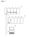
- Fig. 1 is a schematic diagram illustrating a whole configuration of a control device 1 according to an embodiment of the present invention.
- the control device 1 includes a PLC 10, a remote IO (Input/Output) device 20, and an HMI device 30 which are interconnected via a field network 2.
- the PLC 10 monitors and controls at least a target device. More specifically, the PLC 10 includes a processing unit 11 configured to execute a program and one or more IO units 12. These units are interconnected via a system bus 13. As described later, the processing unit 11 collects field information from the IO units 12 which are connected to the processing unit 11 via the system bus 13 and/or the remote IO device 20 which is connected to the processing unit 11 via the field network 2, calculates a status value such as an output value according to the collected information, and also sends out the status value to the other devices through the field network 2.
- the remote IO device 20 includes a communication unit 21 and one or more IO units 22.
- the communication unit 21 sends out field information collected via the IO units 22 to the PLC 10 through the field network 2, and also causes the IO units 22 to output signals according to an instruction from the PLC 10.
- the HMI device 30 presents information to the user based on the status value and the like received via the field network 2, and also allows user to operate to send out the details of the operation to the PLC 10. That is, the HMI device 30, which is an interface for connecting the user and the PLC 10, allows the user to operate and instructs the PLC 10 to perform control or the like on the target device (to stop the target device or to put the target device into operation), and also sequentially updates a value indicating the status of the target device based on information from the PLC 10.
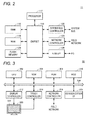
- Fig. 2 is a schematic diagram illustrating the hardware configuration of the processing unit 11 according to the embodiment of the present invention.
- the processing unit 11 includes a processor 112, a chipset 114, a RAM (Random Access Memory) 116, a ROM (Read Only Memory) 118, a FLASH memory 120, a system bus controller 122, a network controller 124, and a USB interface (I/F) 126.
- the chipset 114 and the other components are coupled via respective types of buses.
- the processor 112 and the chipset 114 are configured in accordance with universal computer architecture. That is, the processor 112 interprets and executes instruction codes successively supplied in accordance with an internal clock from the chipset 114.
- the chipset 114 exchanges internal data with the respective connected components, and also generates an instruction code necessary to the processor 112. Further, the chipset 114 has a function of caching data and the like which are acquired as a result of arithmetic processing executed in the processor 112.
- the processing unit 11 has the RAM 116 which is a volatile memory and the ROM 118 and the FLASH memory 120 which are nonvolatile memories as storage units.
- the RAM 116 is a main memory which provides a working memory necessary for the processor 112 to execute a program.
- the ROM 118 and/or the FLASH memory 120 stores various types of program (module) including a real time OS (Operating System), a system program, and an executable program, and data including system setting parameters in a nonvolatile manner.
- the processing unit 11 has the system bus controller 122 and the network controller 124 as communication interfaces. These communication interfaces send output data and receive input data. That is, the system bus controller 122 sends/ receives data transmitted over the system bus 13, and the network controller 124 sends/ receives data transmitted over the field network 2.
- the USB interface 126 is a communication interface for connecting the PLC 10 and the HMI device 30.
- Fig. 3 is a schematic diagram illustrating a hardware configuration of the HMI device 30 according to the embodiment of the present invention. It is assumed that the HMI device 30 according to the embodiment is configured with a universal computer, as an example. However, in order to further improve reliability, dedicated hardware and software may also be adopted.
- the HMI device 30 includes a CPU 302 configured to execute various types of program including an OS, a ROM (Read Only Memory) 308 configured to store the BIOS (Basic Input /Output System) and various types of data, a RAM 306 configured to provide a work area for storing data necessary to execute a program in the CPU 302, and a hard disk (HDD) 310 configured to store a program to be executed in the CPU 302 in a nonvolatile manner.
- the respective parts are interconnected via an internal bus 304.
- the HMI device 30 includes a display 320 as a display unit for presenting information to the user and a display controller 312 for controlling the contents displayed on the display 320.
- the display 320 displays a monitoring/ controlling screen associated with a target device.
- the HMI device 30 includes a touch panel 322, as an input unit to allow the user to operate, arranged to associate with the display 320 and a touch controller 314 for detecting the user operation performed on the touch panel 322.
- the touch panel 322 detects touch operation performed by the user.
- the touch panel 322 is configured to be able to simultaneously detect a plurality of points touched by the user.
- a capacitive touch panel or an optical detection-type touch panel is adopted.
- the HMI device 30 includes a network controller 316 for communicating with the PLC 10 (processing unit 11) and the like and a communication interface (I/F) 318 for communication through an external network (not shown).
- a network controller 316 for communicating with the PLC 10 (processing unit 11) and the like and a communication interface (I/F) 318 for communication through an external network (not shown).
- a control program to be executed by the HMI device 30 is stored in recording media such as a CD-ROM and a DVD-ROM for distribution.
- the control program stored in these recording media is read by a read-out device which supports the program and installed in the hard disk 310 or the like.
- the HMI device 30 may be adapted to download the control program from an external server device via the communication interface 318 or the like for installation.
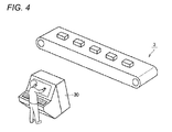
- Fig. 4 is a schematic diagram illustrating an application of the control device 1 according to the embodiment of the present invention.
- the control device 1 monitors and controls one or more target devices associated with a production line 3 (for example, a motor, a solenoid valve, a valve, and various types of processing equipment).
- a production line 3 for example, a motor, a solenoid valve, a valve, and various types of processing equipment.
- an operator hereinafter, also simply referred to as "user” of the production line 3 monitors information displayed on the HMI device 30, and also gives a necessary instruction to a target device (for example, an instruction to put the target device into operation or to stop the target device) by operating the HMI device 30.
- a target device for example, an instruction to put the target device into operation or to stop the target device
- the embodiment adopts a mechanism which does not simply recognize a touch given by the user with only one finger as input operation.
- the control device 1 can not only prevent wrong operation but also enhance a security function since it only enables operation performed by a user who has made a touch gesture which is detected as valid operation.
- the embodiment adopts a touch panel which is capable of detecting multi-touch.
- the control device 1 determines that the user has continued touching the touch panel at least at two points and performed rotating operation by a predetermined angle (for example, 90°) or more, it changes a status value associated with the touched positions of at least two points.
- the "status value” may include not only a value managed in the control device 1 but also a command value and the like output from the control device 1 to the target device. That is, the user can give an instruction to change an operation mode, to put the target device into operation, to stop the target device, or the like by the above described touch operation.
- Figs. 5 and 6 are schematic diagrams for describing examples of user operation according to the embodiment of the present invention.
- an object 350 associated with operation is displayed on the display 320.
- the status value associated with the object 350 is updated.
- the object 350 associated with operation is displayed on the display 320.
- the status value associated with the object 350 is updated.
- Figs. 7A and 7B are schematic diagrams illustrating examples of locus of user operation according to the embodiment of the present invention.
- Rotating operation by a predetermined angle (for example, 90°) or more performed by the user while the user has continued touching the object 350 at least at two points according to the embodiment may include both of the case where the touched two points are rotated respectively as illustrated in Fig. 7A and the case where one of the touched points is not practically moved while the other touched point is rotated as illustrated in Fig. 7B .
- the HMI device 30 determines that the user has continued touching the object 350 at least at two points and performed rotating operation by a predetermined angle or more based on relationship between the touched positions of the at least two points before and after movement of at least one of the touched positions, the HMI device 30 changes the status value associated with the touched positions of the at least two points.
- a target object of the operation may be limited based on relationship between positions touched by the user and a displayed position of the object.
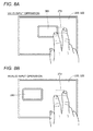
- Figs. 8A and 8B are schematic diagrams for describing an example of prevention of wrong operation according to the embodiment of the present invention.
- Fig. 8A illustrates an example in which touched positions of multi-touch operation by the user are adjacent to the object 350 (valid input operation) and
- Fig. 8B illustrates an example in which touched positions of multi-touch operation by the user are apart from the object 350 (invalid input operation).
- a method for identifying the target object of the touch operation made by the user a method of determining the target object based on relative relationship between a range or positions of the touch operation and an arranged position or a range of the object may be adopted.
- the object 350 as an operation target is determined based on whether at least a portion of the object 350 is covered in a range 370 enclosed by the respective touched positions at the start of the multi-touch operation made by the user.
- the range 370 enclosed by the index finger and middle finger is determined, and since the range 370 and a portion of the object 350 overlap with each other, the object 350 is determined to be the operation target. Then, in response to user operation in which the user has continued touching the object 350 and performed rotating operation by a predetermined angle or more, the status value associated with the object 350 is changed.
- the object 350 is not determined to be the operation target.
- the HMI device 30 displays the object 350 associated with the target device and the touch panel 322 detects touches at two points, on the condition that the object 350 is in the range 370 enclosed by one of the touched positions and the other touched position, the HMI device 30 starts determining whether the rotating operation by the predetermined angle or more for the target device associated with the object 350 has been performed or not.
- a range in which the user should perform touch input may be indicated.
- Fig. 9 is a schematic diagram for describing an example of assistance for input operation according to the embodiment of the present invention.
- a region in which the user should touch to perform operation is displayed on the periphery of the object 350.
- two indicators 360 indicating a range for the user to touch are displayed on both sides of the object 350.
- the status value associated with the object 350 is changed.
- the HMI device 30 displays the indicators 360 as a guide indicating a range in which the rotating operation associated with the object 350 is enabled.
- the indicators 360 may be always displayed on the periphery of each object or on the periphery of any one of objects as triggered by touch operation on the object or on the periphery of the object. In the latter case, the indicators 360 may be removed from the display 320 on the condition that no operation is performed for a predetermined period of time.
- a detection logic a method of determining the rotating operation by the predetermined angle or more based on relationship between a straight line connecting two points detected at the start of touch operation and a straight line connecting two points detected in response to subsequent rotating operation may be adopted.
- Figs. 10A to 10C are schematic diagrams for describing an example of detection logic for rotating operation according to the embodiment of the present invention.
- Fig. 10A illustrates two points detected at the start of touch operation. That is, it is assumed that a point A1 and a point B1 are detected with respective coordinate values (Xa1, Ya1) and (Xb1, Yb1).
- This detection logic can detect both kinds of user operation illustrated in Figs. 7A and 7B .
- the HMI device 30 in response to detection of touches at two points, detects respective touched positions as first and second starting positions (the point A1 and the point B1), and obtains a first position after movement (the point A2) which is a touched position detected subsequently to the first starting position (the point A1) and a second position after movement (the point B2) which is a touched position detected subsequently to the second starting position (the point B1) respectively.
- the HMI device 30 determines that the rotating operation by the predetermined angle or more has been performed.
- a method of estimating a circular arc (curvature) based on a locus of touch operation and, based on the estimated information, determining whether the rotating operation by the predetermined angle or more has been performed may be adopted.
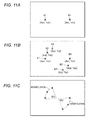
- Figs. 11A to 11C are schematic diagrams for describing another example of detection logic for rotating operation according to the embodiment of the present invention.
- Fig. 11A illustrates two points detected at the start of touch operation. That is, it is assumed that a point A1 and a point B1 are detected with respective coordinate values (Xa1, Ya1) and (Xb1, Yb1).
- a circular arc is obtained by interpolation of coordinate information about the plurality of detected points as illustrated in Fig. 11C . That is, a circular arc is obtained by interpolation of the set of the point A1, the point A2, and the point A3, and a circular arc is obtained by interpolation of the set of the point B1, the point B2, and the point B3. Then, centers and central angles ⁇ and ⁇ 2 resulted from the moving operation made by the user are calculated for the respective circular arcs.
- This detection logic can detect both kinds of user operation illustrated in Figs. 7A and 7B .
- the HMI device 30 in response to detection of touches at two points, detects respective touched positions as first and second starting positions (the point A1 and the point B1), and obtains first positions after movement (the point A2 and the point A3) which are touched positions detected subsequently to the first starting position (the point A1) and second positions after movement (the point B2 and the point B3) which are touched positions detected subsequently to the second starting position (the point B1) respectively.
- the HMI device 30 determines that the rotating operation by the predetermined angle or more has been performed.
- a method of estimating a formed angle based on a locus of touch operation and, based on the estimated information, determining whether rotating operation by a predetermined angle or more has been performed may be adopted.
- Figs. 12A to 12C are schematic diagrams for describing yet another example of detection logic for rotating operation according to the embodiment of the present invention.
- Fig. 12A illustrates two points detected at the start of touch operation. That is, it is assumed that a point A1 and a point B1 are detected with respective coordinate values (Xa1, Ya1) and (Xb1, Yb1).
- an angle formed by the point A1 and the point A2 with the point B1 which has not been practically moved as it is as the center is calculated as illustrated in Fig. 12C . That is, an angle ⁇ 3 which is formed by the three points of the point A1, the point B1, and the point A2 is calculated. Then, whether the formed angle ⁇ 3 obtained by the calculation exceeds a predetermined threshold value or not is determined, and on the condition that the formed angle ⁇ 3 exceeds the threshold value, it is determined that the user has performed rotating operation.
- This detection logic can detect the user operation illustrated in Fig. 7B .
- the HMI device 30 in response to detection of touches at two points, detects respective touched positions as first and second starting positions (the point A1 and the point B 1), and obtains a first position after movement (the point A2) which is a touched position detected subsequently to the first starting position (the point A1). Then, on the condition that an angle ⁇ 3 formed by the first starting position (the point A1) and the first position after movement (the point A2) with the second starting position (the point B1) as reference exceeds a predetermined value, the HMI device 30 determines that the rotating operation by a predetermined angle or more has been performed.
- constraint conditions as described below may be added.
- constraint conditions to detect that the user starts multi-touch i.e., to determine the start of touching state may be added. More specifically, constraint conditions to detect that multi-touch is performed by the user's hand is added to the detection of multi-touch, and on the condition that the constraint conditions are met, it is determined that the touching state is started. Further, constraint conditions to detect that the multi-touch is performed with one hand or with both hands may be adopted.
- Fig. 13 is a schematic diagram for describing an example of conditions for starting detection logic for rotating operation according to the embodiment of the present invention. Referring to Fig. 13 , it is assumed that multi-touch is performed and a point A1 (Xa1, Ya1) and a point B1 (Xb1, Yb1) are detected as initial values, respectively.
- condition for starting detection logic in that case, a condition that horizontal and vertical distances between the detected two points are respectively within predetermined ranges may be adopted.
- a condition that a horizontal distance L between the point A1 and the point B1 is within a predetermined range and also a vertical distance H between the point A1 and the point B 1 is a predetermined value or less is considered.
- the condition may be used as a condition for detecting that the user has performed multi-touch with two fingers of one hand.
- condition that the horizontal distance L between the point A1 and the point B 1 is a predetermined value or more and also the vertical distance H between the point A1 and the point B 1 is within a predetermined range is considered.
- the condition may be used as a condition for detecting that the user has performed multi-touch with both palms (i.e., with both hands).
- the HMI device 30 may be adapted to enable the aforementioned detection logics on the condition that multi-touch is detected and also any of the above described conditions is met.
- the HMI device 30 starts determining whether rotating operation by a predetermined angle or more has been performed or not.
- a duration of determination as to whether multi-touch has been performed before rotating operation is performed may be limited. That is, usual user operation is expected to be completed within a certain period of time after detection of multi-touch. Then, the determination about rotating operation may be treated as time-out and stopped when a predetermined time is reached after multi-touch is detected and before rotating operation by a predetermined angle is detected.
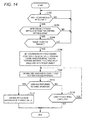
- Fig. 14 is a flow chart describing a procedure for processing a touch input in the control device 1 according to the embodiment of the present invention. Typically, steps described in Fig. 14 are performed by the CPU 302 of the HMI device 30 executing the control program.
- the HMI device 30 determines whether the user has performed multi-touch or not (step S100). More specifically, the CPU 302 of the HMI device 30 determines whether coordinates for a plurality of touched positions are simultaneously detected by the touch panel 322. In the case where it is determined that the user has not performed multi-touch (in the case of NO in step S100), the process of step S100 is repeated.
- the HMI device 30 determines whether the detected multi-touch meets the conditions for starting determination or not (step S102). More specifically, as described above, whether the condition that the horizontal and vertical distances between the detected two points are respectively within predetermined ranges is met or not is determined. In the case where the detected multi-touch does not meet the conditions for starting determination (in the case of NO in step S102), the processes from step S100 are performed again.
- the HMI device 30 determines whether the target object is present or not based on the coordinates for two touched positions of the detected multi-touch (step S104). More specifically, as described above, whether any object is displayed in a range enclosed by the two touched positions or not is determined. In the case where a target object is not present (in the case of NO in step S104), the processes from step S100 are performed again.
- the HMI device 30 sets the coordinates for two touched positions of the detected multi-touch as coordinates for initial touched positions and also identifies a status value associated with the target object (step S106).
- the HMI device 30 obtains time variation of the coordinates for the two touched positions which are subsequently input while the multi-touch state is being continued (step S108). Then, the HMI device 30 determines whether the user has performed rotating operation by a predetermined angle or more based on the time variation of the coordinates for the two touched positions (step S110). Specifically, as described with reference to Figs. 10 and 11 , whether rotating operation by a predetermined angle or more has been performed or not is determined based on the time variation of the detected coordinates for the touched positions.
- the HMI device 30 changes the status value associated with the target object (step S 112).
- an instruction to start or stop or the like is issued to the target machinery, equipment, or the like, for example. Then, the procedure ends.
- step S110 the HMI device 30 determines whether the multi-touch is being continued or not (step S 114). In the case where it is determined that the multi-touch is being continued (in the case of YES in step S114), the processes from step S108 are repeated.
- control unit PLC
- HMI device input display unit
- the present invention may be adapted to detect such user operation as described below in place of or in addition to the rotating operation.
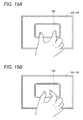
- Figs. 15A and 15B are schematic diagrams for describing an example of user operation according to another embodiment of the present invention.
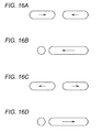
- Figs. 16A to 16D are schematic diagrams illustrating examples of locus of user operation according to other embodiments of the present invention.
- an object 350 associated with operation is displayed on the display 320.
- a status value associated with the object 350 is updated.
- the present invention may update the status value associated with the object 350 in response to the user operation in which the user moves the fingers on the touched two points closer together.
- the present invention may update the status value associated with the object 350 in response to user operation in which the user moves the fingers on the touched two points apart from each other. That is, the present invention may update the status value associated with the object 350 by detecting user operation similar to so-called pinch in/pinch out operation.
- Figs. 16A to 16D Those kinds of operation example of changing a distance between touched two points include operation illustrated in Figs. 16A to 16D . That is, the case where touched two points are moved closer to each other as illustrated in Fig. 16A , the case where one of touched two points is not practically moved while the other touched point is moved closer to the unmoved touched point as illustrated in Fig. 16B , the case where touched two points are moved apart from each other as illustrated in Fig. 16C , and the case where one of touched two points is not practically moved while the other touched point is moved apart from the unmoved touched point as illustrated in Fig. 16D may be included.
- the present invention can further improve operability.
- the embodiment a mechanism which does not simply recognize a touch given by the user with only one finger as input operation is adopted.
- the embodiment can not only prevent wrong operation but also enhance a security function since only a user who know a touch operation for enabling the operation can perform the operation..
Landscapes
- Engineering & Computer Science (AREA)
- General Engineering & Computer Science (AREA)
- Theoretical Computer Science (AREA)
- Human Computer Interaction (AREA)
- Physics & Mathematics (AREA)
- General Physics & Mathematics (AREA)
- User Interface Of Digital Computer (AREA)
- Position Input By Displaying (AREA)
Applications Claiming Priority (1)
| Application Number | Priority Date | Filing Date | Title |
|---|---|---|---|
| JP2012247305A JP6163733B2 (ja) | 2012-11-09 | 2012-11-09 | 制御装置および制御プログラム |
Publications (3)
| Publication Number | Publication Date |
|---|---|
| EP2731004A2 true EP2731004A2 (fr) | 2014-05-14 |
| EP2731004A3 EP2731004A3 (fr) | 2015-06-24 |
| EP2731004B1 EP2731004B1 (fr) | 2018-08-08 |
Family
ID=49641477
Family Applications (1)
| Application Number | Title | Priority Date | Filing Date |
|---|---|---|---|
| EP13192104.1A Not-in-force EP2731004B1 (fr) | 2012-11-09 | 2013-11-08 | Dispositif de commande et programme de commande |
Country Status (4)
| Country | Link |
|---|---|
| US (2) | US9262069B2 (fr) |
| EP (1) | EP2731004B1 (fr) |
| JP (1) | JP6163733B2 (fr) |
| CN (1) | CN103809868B (fr) |
Cited By (1)
| Publication number | Priority date | Publication date | Assignee | Title |
|---|---|---|---|---|
| EP2860599A1 (fr) * | 2013-08-02 | 2015-04-15 | Rockwell Automation Control Solutions (HARBIN) Co., Ltd. | Dispositif de commande avec un contrôleur à logique programmable PLC et avec un écran tactile |
Families Citing this family (8)
| Publication number | Priority date | Publication date | Assignee | Title |
|---|---|---|---|---|
| USD749115S1 (en) * | 2015-02-20 | 2016-02-09 | Translate Abroad, Inc. | Mobile device with graphical user interface |
| CN104777998B (zh) * | 2015-03-17 | 2018-12-18 | 惠州Tcl移动通信有限公司 | 图片旋转的方法及智能终端 |
| US10656780B2 (en) | 2018-01-12 | 2020-05-19 | Mitutoyo Corporation | Position specifying method and program |
| US20190220185A1 (en) * | 2018-01-12 | 2019-07-18 | Mitutoyo Corporation | Image measurement apparatus and computer readable medium |
| JP7078403B2 (ja) * | 2018-01-12 | 2022-05-31 | 株式会社ミツトヨ | 画像測定機およびプログラム |
| US20220197487A1 (en) * | 2019-06-19 | 2022-06-23 | Ja Beom KOO | View mode change device using touch pattern input and method therefor |
| CN114676358B (zh) * | 2022-03-21 | 2025-04-15 | 北京字跳网络技术有限公司 | 控件的显示方法、装置、电子设备、存储介质和程序产品 |
| CN115220381A (zh) * | 2022-07-19 | 2022-10-21 | 上海繁易信息科技股份有限公司 | 一种智能一体机控制器 |
Family Cites Families (21)
| Publication number | Priority date | Publication date | Assignee | Title |
|---|---|---|---|---|
| JP3913832B2 (ja) * | 1997-03-31 | 2007-05-09 | 武藤工業株式会社 | 円弧補間処理方法 |
| JP2000010608A (ja) | 1998-06-24 | 2000-01-14 | Omron Corp | 通信装置、plcユニットおよび表示器 |
| JP4803883B2 (ja) * | 2000-01-31 | 2011-10-26 | キヤノン株式会社 | 位置情報処理装置及びその方法及びそのプログラム。 |
| JP4686886B2 (ja) * | 2001-04-06 | 2011-05-25 | ソニー株式会社 | 情報処理装置 |
| JP2003099205A (ja) * | 2001-09-21 | 2003-04-04 | Ricoh Co Ltd | 表示一体型座標入力装置 |
| JP2004118383A (ja) * | 2002-09-25 | 2004-04-15 | Kawasaki Heavy Ind Ltd | 仮想スイッチ類提供方法および装置 |
| AU2006332488A1 (en) * | 2005-12-30 | 2007-07-12 | Apple Inc. | Portable electronic device with multi-touch input |
| JP2008070968A (ja) * | 2006-09-12 | 2008-03-27 | Funai Electric Co Ltd | 表示処理装置 |
| JP4933997B2 (ja) * | 2007-09-25 | 2012-05-16 | 株式会社山武 | 数値設定方法およびタッチパネル式操作装置 |
| US8446373B2 (en) * | 2008-02-08 | 2013-05-21 | Synaptics Incorporated | Method and apparatus for extended adjustment based on relative positioning of multiple objects contemporaneously in a sensing region |
| JP5228755B2 (ja) * | 2008-09-29 | 2013-07-03 | 富士通株式会社 | 携帯端末装置、表示制御方法および表示制御プログラム |
| WO2011045861A1 (fr) * | 2009-10-16 | 2011-04-21 | パイオニア株式会社 | Dispositif d'affichage de carte, procédé d'affichage de carte et programme d'affichage de carte |
| US20110205169A1 (en) * | 2010-02-24 | 2011-08-25 | Primax Electronics Ltd. | Multi-touch input apparatus and its interface method using hybrid resolution based touch data |
| US20110225524A1 (en) * | 2010-03-10 | 2011-09-15 | Cifra Christopher G | Multi-Touch Editing in a Graphical Programming Language |
| TW201133298A (en) * | 2010-03-25 | 2011-10-01 | Novatek Microelectronics Corp | Touch sensing method and system using the same |
| JP5230684B2 (ja) * | 2010-05-13 | 2013-07-10 | パナソニック株式会社 | 電子機器、表示方法、及びプログラム |
| CN102375580A (zh) * | 2010-08-06 | 2012-03-14 | 昆盈企业股份有限公司 | 多点控制的操作方法 |
| WO2012024022A2 (fr) * | 2010-08-20 | 2012-02-23 | University Of Massachusetts | Enregistrement de la main et des doigts destiné à des applications de commande |
| KR101739054B1 (ko) * | 2010-09-08 | 2017-05-24 | 삼성전자주식회사 | 디바이스상의 움직임 제어 방법 및 장치 |
| CN102736771B (zh) * | 2011-03-31 | 2016-06-22 | 比亚迪股份有限公司 | 多点旋转运动的识别方法及装置 |
| US20140028554A1 (en) * | 2012-07-26 | 2014-01-30 | Google Inc. | Recognizing gesture on tactile input device |
-
2012
- 2012-11-09 JP JP2012247305A patent/JP6163733B2/ja active Active
-
2013
- 2013-11-08 EP EP13192104.1A patent/EP2731004B1/fr not_active Not-in-force
- 2013-11-08 US US14/074,939 patent/US9262069B2/en active Active
- 2013-11-11 CN CN201310556383.6A patent/CN103809868B/zh not_active Expired - Fee Related
-
2015
- 2015-12-22 US US14/978,268 patent/US20160109975A1/en not_active Abandoned
Cited By (1)
| Publication number | Priority date | Publication date | Assignee | Title |
|---|---|---|---|---|
| EP2860599A1 (fr) * | 2013-08-02 | 2015-04-15 | Rockwell Automation Control Solutions (HARBIN) Co., Ltd. | Dispositif de commande avec un contrôleur à logique programmable PLC et avec un écran tactile |
Also Published As
| Publication number | Publication date |
|---|---|
| US20140132537A1 (en) | 2014-05-15 |
| EP2731004B1 (fr) | 2018-08-08 |
| JP6163733B2 (ja) | 2017-07-19 |
| EP2731004A3 (fr) | 2015-06-24 |
| CN103809868A (zh) | 2014-05-21 |
| US9262069B2 (en) | 2016-02-16 |
| US20160109975A1 (en) | 2016-04-21 |
| CN103809868B (zh) | 2018-07-17 |
| JP2014096035A (ja) | 2014-05-22 |
Similar Documents
| Publication | Publication Date | Title |
|---|---|---|
| US9262069B2 (en) | Control device having an input display for detecting two touch points | |
| US10503373B2 (en) | Visual feedback for highlight-driven gesture user interfaces | |
| EP3025218B1 (fr) | Tablette tactile à régions multiples | |
| US9760238B2 (en) | Electronic device and method for identifying window control command in a multi-window system | |
| US8878787B2 (en) | Multi-touch user input based on multiple quick-point controllers | |
| KR101636665B1 (ko) | 프로그래머블 표시기 및 그 화면 조작 처리 프로그램 | |
| US9354780B2 (en) | Gesture-based selection and movement of objects | |
| KR102390783B1 (ko) | 확률적 터치 감지 | |
| JP5915061B2 (ja) | 情報処理装置および方法、プログラム、並びに記録媒体 | |
| US9773329B2 (en) | Interaction with a graph for device control | |
| US10282087B2 (en) | Multi-touch based drawing input method and apparatus | |
| CN111766995A (zh) | 数值调节控制方法、装置、电子设备及存储介质 | |
| US20180267688A1 (en) | Interaction method and device for controlling virtual object | |
| US11567571B2 (en) | Remote control of a device via a virtual interface | |
| JP2017525000A (ja) | 操作装置及び制御システム | |
| CN107329690A (zh) | 虚拟对象控制方法及装置、存储介质、电子设备 | |
| WO2018160258A1 (fr) | Système et procédés pour étendre la portée efficace d'un doigt d'utilisateur sur une interface utilisateur à écran tactile | |
| CN105653177A (zh) | 终端设备界面的可点击元素的选择方法和终端设备 | |
| US20130234997A1 (en) | Input processing apparatus, input processing program, and input processing method | |
| WO2016081280A1 (fr) | Procédé et système pour qu'un pointeur de souris suive automatiquement un curseur | |
| EP3387500B1 (fr) | Robot industriel, et procédé permettant de commander le robot afin de sélectionner automatiquement le code de programme à exécuter ensuite | |
| KR101503159B1 (ko) | 시선의 위치를 감지하여 터치스크린을 제어하는 방법 | |
| US20180300052A1 (en) | Operation input apparatus, information processing apparatus, information processing method, and program | |
| US11079915B2 (en) | System and method of using multiple touch inputs for controller interaction in industrial control systems | |
| KR102516422B1 (ko) | 터치 입력에 의해 제어되는 단말 및 단말 제어 방법 |
Legal Events
| Date | Code | Title | Description |
|---|---|---|---|
| PUAI | Public reference made under article 153(3) epc to a published international application that has entered the european phase |
Free format text: ORIGINAL CODE: 0009012 |
|
| 17P | Request for examination filed |
Effective date: 20131108 |
|
| AK | Designated contracting states |
Kind code of ref document: A2 Designated state(s): AL AT BE BG CH CY CZ DE DK EE ES FI FR GB GR HR HU IE IS IT LI LT LU LV MC MK MT NL NO PL PT RO RS SE SI SK SM TR |
|
| AX | Request for extension of the european patent |
Extension state: BA ME |
|
| PUAL | Search report despatched |
Free format text: ORIGINAL CODE: 0009013 |
|
| AK | Designated contracting states |
Kind code of ref document: A3 Designated state(s): AL AT BE BG CH CY CZ DE DK EE ES FI FR GB GR HR HU IE IS IT LI LT LU LV MC MK MT NL NO PL PT RO RS SE SI SK SM TR |
|
| AX | Request for extension of the european patent |
Extension state: BA ME |
|
| RIC1 | Information provided on ipc code assigned before grant |
Ipc: G05B 19/05 20060101ALI20150515BHEP Ipc: G06F 3/0484 20130101ALI20150515BHEP Ipc: G06F 3/0488 20130101AFI20150515BHEP |
|
| 17Q | First examination report despatched |
Effective date: 20160503 |
|
| GRAP | Despatch of communication of intention to grant a patent |
Free format text: ORIGINAL CODE: EPIDOSNIGR1 |
|
| STAA | Information on the status of an ep patent application or granted ep patent |
Free format text: STATUS: GRANT OF PATENT IS INTENDED |
|
| INTG | Intention to grant announced |
Effective date: 20180326 |
|
| GRAS | Grant fee paid |
Free format text: ORIGINAL CODE: EPIDOSNIGR3 |
|
| GRAA | (expected) grant |
Free format text: ORIGINAL CODE: 0009210 |
|
| STAA | Information on the status of an ep patent application or granted ep patent |
Free format text: STATUS: THE PATENT HAS BEEN GRANTED |
|
| AK | Designated contracting states |
Kind code of ref document: B1 Designated state(s): AL AT BE BG CH CY CZ DE DK EE ES FI FR GB GR HR HU IE IS IT LI LT LU LV MC MK MT NL NO PL PT RO RS SE SI SK SM TR |
|
| REG | Reference to a national code |
Ref country code: GB Ref legal event code: FG4D |
|
| REG | Reference to a national code |
Ref country code: CH Ref legal event code: EP Ref country code: AT Ref legal event code: REF Ref document number: 1027770 Country of ref document: AT Kind code of ref document: T Effective date: 20180815 |
|
| REG | Reference to a national code |
Ref country code: IE Ref legal event code: FG4D |
|
| REG | Reference to a national code |
Ref country code: DE Ref legal event code: R096 Ref document number: 602013041529 Country of ref document: DE |
|
| REG | Reference to a national code |
Ref country code: NL Ref legal event code: MP Effective date: 20180808 |
|
| REG | Reference to a national code |
Ref country code: LT Ref legal event code: MG4D |
|
| REG | Reference to a national code |
Ref country code: AT Ref legal event code: MK05 Ref document number: 1027770 Country of ref document: AT Kind code of ref document: T Effective date: 20180808 |
|
| PG25 | Lapsed in a contracting state [announced via postgrant information from national office to epo] |
Ref country code: NO Free format text: LAPSE BECAUSE OF FAILURE TO SUBMIT A TRANSLATION OF THE DESCRIPTION OR TO PAY THE FEE WITHIN THE PRESCRIBED TIME-LIMIT Effective date: 20181108 Ref country code: GR Free format text: LAPSE BECAUSE OF FAILURE TO SUBMIT A TRANSLATION OF THE DESCRIPTION OR TO PAY THE FEE WITHIN THE PRESCRIBED TIME-LIMIT Effective date: 20181109 Ref country code: IS Free format text: LAPSE BECAUSE OF FAILURE TO SUBMIT A TRANSLATION OF THE DESCRIPTION OR TO PAY THE FEE WITHIN THE PRESCRIBED TIME-LIMIT Effective date: 20181208 Ref country code: RS Free format text: LAPSE BECAUSE OF FAILURE TO SUBMIT A TRANSLATION OF THE DESCRIPTION OR TO PAY THE FEE WITHIN THE PRESCRIBED TIME-LIMIT Effective date: 20180808 Ref country code: NL Free format text: LAPSE BECAUSE OF FAILURE TO SUBMIT A TRANSLATION OF THE DESCRIPTION OR TO PAY THE FEE WITHIN THE PRESCRIBED TIME-LIMIT Effective date: 20180808 Ref country code: BG Free format text: LAPSE BECAUSE OF FAILURE TO SUBMIT A TRANSLATION OF THE DESCRIPTION OR TO PAY THE FEE WITHIN THE PRESCRIBED TIME-LIMIT Effective date: 20181108 Ref country code: AT Free format text: LAPSE BECAUSE OF FAILURE TO SUBMIT A TRANSLATION OF THE DESCRIPTION OR TO PAY THE FEE WITHIN THE PRESCRIBED TIME-LIMIT Effective date: 20180808 Ref country code: FI Free format text: LAPSE BECAUSE OF FAILURE TO SUBMIT A TRANSLATION OF THE DESCRIPTION OR TO PAY THE FEE WITHIN THE PRESCRIBED TIME-LIMIT Effective date: 20180808 Ref country code: LT Free format text: LAPSE BECAUSE OF FAILURE TO SUBMIT A TRANSLATION OF THE DESCRIPTION OR TO PAY THE FEE WITHIN THE PRESCRIBED TIME-LIMIT Effective date: 20180808 Ref country code: PL Free format text: LAPSE BECAUSE OF FAILURE TO SUBMIT A TRANSLATION OF THE DESCRIPTION OR TO PAY THE FEE WITHIN THE PRESCRIBED TIME-LIMIT Effective date: 20180808 Ref country code: SE Free format text: LAPSE BECAUSE OF FAILURE TO SUBMIT A TRANSLATION OF THE DESCRIPTION OR TO PAY THE FEE WITHIN THE PRESCRIBED TIME-LIMIT Effective date: 20180808 |
|
| PG25 | Lapsed in a contracting state [announced via postgrant information from national office to epo] |
Ref country code: AL Free format text: LAPSE BECAUSE OF FAILURE TO SUBMIT A TRANSLATION OF THE DESCRIPTION OR TO PAY THE FEE WITHIN THE PRESCRIBED TIME-LIMIT Effective date: 20180808 Ref country code: LV Free format text: LAPSE BECAUSE OF FAILURE TO SUBMIT A TRANSLATION OF THE DESCRIPTION OR TO PAY THE FEE WITHIN THE PRESCRIBED TIME-LIMIT Effective date: 20180808 Ref country code: HR Free format text: LAPSE BECAUSE OF FAILURE TO SUBMIT A TRANSLATION OF THE DESCRIPTION OR TO PAY THE FEE WITHIN THE PRESCRIBED TIME-LIMIT Effective date: 20180808 |
|
| PG25 | Lapsed in a contracting state [announced via postgrant information from national office to epo] |
Ref country code: EE Free format text: LAPSE BECAUSE OF FAILURE TO SUBMIT A TRANSLATION OF THE DESCRIPTION OR TO PAY THE FEE WITHIN THE PRESCRIBED TIME-LIMIT Effective date: 20180808 Ref country code: ES Free format text: LAPSE BECAUSE OF FAILURE TO SUBMIT A TRANSLATION OF THE DESCRIPTION OR TO PAY THE FEE WITHIN THE PRESCRIBED TIME-LIMIT Effective date: 20180808 Ref country code: IT Free format text: LAPSE BECAUSE OF FAILURE TO SUBMIT A TRANSLATION OF THE DESCRIPTION OR TO PAY THE FEE WITHIN THE PRESCRIBED TIME-LIMIT Effective date: 20180808 Ref country code: RO Free format text: LAPSE BECAUSE OF FAILURE TO SUBMIT A TRANSLATION OF THE DESCRIPTION OR TO PAY THE FEE WITHIN THE PRESCRIBED TIME-LIMIT Effective date: 20180808 Ref country code: CZ Free format text: LAPSE BECAUSE OF FAILURE TO SUBMIT A TRANSLATION OF THE DESCRIPTION OR TO PAY THE FEE WITHIN THE PRESCRIBED TIME-LIMIT Effective date: 20180808 |
|
| REG | Reference to a national code |
Ref country code: DE Ref legal event code: R097 Ref document number: 602013041529 Country of ref document: DE |
|
| PG25 | Lapsed in a contracting state [announced via postgrant information from national office to epo] |
Ref country code: SK Free format text: LAPSE BECAUSE OF FAILURE TO SUBMIT A TRANSLATION OF THE DESCRIPTION OR TO PAY THE FEE WITHIN THE PRESCRIBED TIME-LIMIT Effective date: 20180808 Ref country code: SM Free format text: LAPSE BECAUSE OF FAILURE TO SUBMIT A TRANSLATION OF THE DESCRIPTION OR TO PAY THE FEE WITHIN THE PRESCRIBED TIME-LIMIT Effective date: 20180808 Ref country code: DK Free format text: LAPSE BECAUSE OF FAILURE TO SUBMIT A TRANSLATION OF THE DESCRIPTION OR TO PAY THE FEE WITHIN THE PRESCRIBED TIME-LIMIT Effective date: 20180808 |
|
| PLBE | No opposition filed within time limit |
Free format text: ORIGINAL CODE: 0009261 |
|
| STAA | Information on the status of an ep patent application or granted ep patent |
Free format text: STATUS: NO OPPOSITION FILED WITHIN TIME LIMIT |
|
| REG | Reference to a national code |
Ref country code: CH Ref legal event code: PL |
|
| 26N | No opposition filed |
Effective date: 20190509 |
|
| GBPC | Gb: european patent ceased through non-payment of renewal fee |
Effective date: 20181108 |
|
| PG25 | Lapsed in a contracting state [announced via postgrant information from national office to epo] |
Ref country code: LU Free format text: LAPSE BECAUSE OF NON-PAYMENT OF DUE FEES Effective date: 20181108 Ref country code: MC Free format text: LAPSE BECAUSE OF FAILURE TO SUBMIT A TRANSLATION OF THE DESCRIPTION OR TO PAY THE FEE WITHIN THE PRESCRIBED TIME-LIMIT Effective date: 20180808 |
|
| REG | Reference to a national code |
Ref country code: BE Ref legal event code: MM Effective date: 20181130 |
|
| REG | Reference to a national code |
Ref country code: IE Ref legal event code: MM4A |
|
| PG25 | Lapsed in a contracting state [announced via postgrant information from national office to epo] |
Ref country code: CH Free format text: LAPSE BECAUSE OF NON-PAYMENT OF DUE FEES Effective date: 20181130 Ref country code: SI Free format text: LAPSE BECAUSE OF FAILURE TO SUBMIT A TRANSLATION OF THE DESCRIPTION OR TO PAY THE FEE WITHIN THE PRESCRIBED TIME-LIMIT Effective date: 20180808 Ref country code: LI Free format text: LAPSE BECAUSE OF NON-PAYMENT OF DUE FEES Effective date: 20181130 |
|
| PG25 | Lapsed in a contracting state [announced via postgrant information from national office to epo] |
Ref country code: IE Free format text: LAPSE BECAUSE OF NON-PAYMENT OF DUE FEES Effective date: 20181108 Ref country code: FR Free format text: LAPSE BECAUSE OF NON-PAYMENT OF DUE FEES Effective date: 20181130 |
|
| PG25 | Lapsed in a contracting state [announced via postgrant information from national office to epo] |
Ref country code: BE Free format text: LAPSE BECAUSE OF NON-PAYMENT OF DUE FEES Effective date: 20181130 |
|
| PG25 | Lapsed in a contracting state [announced via postgrant information from national office to epo] |
Ref country code: GB Free format text: LAPSE BECAUSE OF NON-PAYMENT OF DUE FEES Effective date: 20181108 |
|
| PG25 | Lapsed in a contracting state [announced via postgrant information from national office to epo] |
Ref country code: MT Free format text: LAPSE BECAUSE OF NON-PAYMENT OF DUE FEES Effective date: 20181108 |
|
| PG25 | Lapsed in a contracting state [announced via postgrant information from national office to epo] |
Ref country code: TR Free format text: LAPSE BECAUSE OF FAILURE TO SUBMIT A TRANSLATION OF THE DESCRIPTION OR TO PAY THE FEE WITHIN THE PRESCRIBED TIME-LIMIT Effective date: 20180808 |
|
| PG25 | Lapsed in a contracting state [announced via postgrant information from national office to epo] |
Ref country code: PT Free format text: LAPSE BECAUSE OF FAILURE TO SUBMIT A TRANSLATION OF THE DESCRIPTION OR TO PAY THE FEE WITHIN THE PRESCRIBED TIME-LIMIT Effective date: 20180808 |
|
| PG25 | Lapsed in a contracting state [announced via postgrant information from national office to epo] |
Ref country code: CY Free format text: LAPSE BECAUSE OF FAILURE TO SUBMIT A TRANSLATION OF THE DESCRIPTION OR TO PAY THE FEE WITHIN THE PRESCRIBED TIME-LIMIT Effective date: 20180808 Ref country code: MK Free format text: LAPSE BECAUSE OF NON-PAYMENT OF DUE FEES Effective date: 20180808 Ref country code: HU Free format text: LAPSE BECAUSE OF FAILURE TO SUBMIT A TRANSLATION OF THE DESCRIPTION OR TO PAY THE FEE WITHIN THE PRESCRIBED TIME-LIMIT; INVALID AB INITIO Effective date: 20131108 |
|
| PGFP | Annual fee paid to national office [announced via postgrant information from national office to epo] |
Ref country code: DE Payment date: 20230929 Year of fee payment: 11 |
|
| REG | Reference to a national code |
Ref country code: DE Ref legal event code: R119 Ref document number: 602013041529 Country of ref document: DE |
|
| PG25 | Lapsed in a contracting state [announced via postgrant information from national office to epo] |
Ref country code: DE Free format text: LAPSE BECAUSE OF NON-PAYMENT OF DUE FEES Effective date: 20250603 |