EP2731353B1 - Appareil et procédé permettant de mesurer une pluralité de haut-parleurs - Google Patents
Appareil et procédé permettant de mesurer une pluralité de haut-parleurs Download PDFInfo
- Publication number
- EP2731353B1 EP2731353B1 EP13197826.4A EP13197826A EP2731353B1 EP 2731353 B1 EP2731353 B1 EP 2731353B1 EP 13197826 A EP13197826 A EP 13197826A EP 2731353 B1 EP2731353 B1 EP 2731353B1
- Authority
- EP
- European Patent Office
- Prior art keywords
- loudspeaker
- microphone
- signals
- length
- sound
- Prior art date
- Legal status (The legal status is an assumption and is not a legal conclusion. Google has not performed a legal analysis and makes no representation as to the accuracy of the status listed.)
- Active
Links
Images




Classifications
-
- H—ELECTRICITY
- H04—ELECTRIC COMMUNICATION TECHNIQUE
- H04R—LOUDSPEAKERS, MICROPHONES, GRAMOPHONE PICK-UPS OR LIKE ACOUSTIC ELECTROMECHANICAL TRANSDUCERS; ELECTRIC HEARING AIDS; PUBLIC ADDRESS SYSTEMS
- H04R1/00—Details of transducers, loudspeakers or microphones
- H04R1/20—Arrangements for obtaining desired frequency or directional characteristics
- H04R1/32—Arrangements for obtaining desired frequency or directional characteristics for obtaining desired directional characteristic only
- H04R1/40—Arrangements for obtaining desired frequency or directional characteristics for obtaining desired directional characteristic only by combining a number of identical transducers
- H04R1/406—Arrangements for obtaining desired frequency or directional characteristics for obtaining desired directional characteristic only by combining a number of identical transducers microphones
-
- H—ELECTRICITY
- H04—ELECTRIC COMMUNICATION TECHNIQUE
- H04R—LOUDSPEAKERS, MICROPHONES, GRAMOPHONE PICK-UPS OR LIKE ACOUSTIC ELECTROMECHANICAL TRANSDUCERS; ELECTRIC HEARING AIDS; PUBLIC ADDRESS SYSTEMS
- H04R29/00—Monitoring arrangements; Testing arrangements
- H04R29/001—Monitoring arrangements; Testing arrangements for loudspeakers
- H04R29/002—Loudspeaker arrays
-
- H—ELECTRICITY
- H04—ELECTRIC COMMUNICATION TECHNIQUE
- H04R—LOUDSPEAKERS, MICROPHONES, GRAMOPHONE PICK-UPS OR LIKE ACOUSTIC ELECTROMECHANICAL TRANSDUCERS; ELECTRIC HEARING AIDS; PUBLIC ADDRESS SYSTEMS
- H04R3/00—Circuits for transducers
- H04R3/005—Circuits for transducers for combining the signals of two or more microphones
-
- H—ELECTRICITY
- H04—ELECTRIC COMMUNICATION TECHNIQUE
- H04R—LOUDSPEAKERS, MICROPHONES, GRAMOPHONE PICK-UPS OR LIKE ACOUSTIC ELECTROMECHANICAL TRANSDUCERS; ELECTRIC HEARING AIDS; PUBLIC ADDRESS SYSTEMS
- H04R5/00—Stereophonic arrangements
- H04R5/027—Spatial or constructional arrangements of microphones, e.g. in dummy heads
-
- H—ELECTRICITY
- H04—ELECTRIC COMMUNICATION TECHNIQUE
- H04R—LOUDSPEAKERS, MICROPHONES, GRAMOPHONE PICK-UPS OR LIKE ACOUSTIC ELECTROMECHANICAL TRANSDUCERS; ELECTRIC HEARING AIDS; PUBLIC ADDRESS SYSTEMS
- H04R1/00—Details of transducers, loudspeakers or microphones
- H04R1/02—Casings; Cabinets ; Supports therefor; Mountings therein
-
- H—ELECTRICITY
- H04—ELECTRIC COMMUNICATION TECHNIQUE
- H04R—LOUDSPEAKERS, MICROPHONES, GRAMOPHONE PICK-UPS OR LIKE ACOUSTIC ELECTROMECHANICAL TRANSDUCERS; ELECTRIC HEARING AIDS; PUBLIC ADDRESS SYSTEMS
- H04R1/00—Details of transducers, loudspeakers or microphones
- H04R1/08—Mouthpieces; Microphones; Attachments therefor
-
- H—ELECTRICITY
- H04—ELECTRIC COMMUNICATION TECHNIQUE
- H04R—LOUDSPEAKERS, MICROPHONES, GRAMOPHONE PICK-UPS OR LIKE ACOUSTIC ELECTROMECHANICAL TRANSDUCERS; ELECTRIC HEARING AIDS; PUBLIC ADDRESS SYSTEMS
- H04R2201/00—Details of transducers, loudspeakers or microphones covered by H04R1/00 but not provided for in any of its subgroups
- H04R2201/02—Details casings, cabinets or mounting therein for transducers covered by H04R1/02 but not provided for in any of its subgroups
-
- H—ELECTRICITY
- H04—ELECTRIC COMMUNICATION TECHNIQUE
- H04R—LOUDSPEAKERS, MICROPHONES, GRAMOPHONE PICK-UPS OR LIKE ACOUSTIC ELECTROMECHANICAL TRANSDUCERS; ELECTRIC HEARING AIDS; PUBLIC ADDRESS SYSTEMS
- H04R2201/00—Details of transducers, loudspeakers or microphones covered by H04R1/00 but not provided for in any of its subgroups
- H04R2201/40—Details of arrangements for obtaining desired directional characteristic by combining a number of identical transducers covered by H04R1/40 but not provided for in any of its subgroups
- H04R2201/401—2D or 3D arrays of transducers
-
- H—ELECTRICITY
- H04—ELECTRIC COMMUNICATION TECHNIQUE
- H04R—LOUDSPEAKERS, MICROPHONES, GRAMOPHONE PICK-UPS OR LIKE ACOUSTIC ELECTROMECHANICAL TRANSDUCERS; ELECTRIC HEARING AIDS; PUBLIC ADDRESS SYSTEMS
- H04R2420/00—Details of connection covered by H04R, not provided for in its groups
- H04R2420/05—Detection of connection of loudspeakers or headphones to amplifiers
-
- H—ELECTRICITY
- H04—ELECTRIC COMMUNICATION TECHNIQUE
- H04R—LOUDSPEAKERS, MICROPHONES, GRAMOPHONE PICK-UPS OR LIKE ACOUSTIC ELECTROMECHANICAL TRANSDUCERS; ELECTRIC HEARING AIDS; PUBLIC ADDRESS SYSTEMS
- H04R2430/00—Signal processing covered by H04R, not provided for in its groups
- H04R2430/20—Processing of the output signals of the acoustic transducers of an array for obtaining a desired directivity characteristic
- H04R2430/21—Direction finding using differential microphone array [DMA]
-
- H—ELECTRICITY
- H04—ELECTRIC COMMUNICATION TECHNIQUE
- H04S—STEREOPHONIC SYSTEMS
- H04S2400/00—Details of stereophonic systems covered by H04S but not provided for in its groups
- H04S2400/03—Aspects of down-mixing multi-channel audio to configurations with lower numbers of playback channels, e.g. 7.1 -> 5.1
-
- H—ELECTRICITY
- H04—ELECTRIC COMMUNICATION TECHNIQUE
- H04S—STEREOPHONIC SYSTEMS
- H04S2400/00—Details of stereophonic systems covered by H04S but not provided for in its groups
- H04S2400/15—Aspects of sound capture and related signal processing for recording or reproduction
-
- H—ELECTRICITY
- H04—ELECTRIC COMMUNICATION TECHNIQUE
- H04S—STEREOPHONIC SYSTEMS
- H04S2420/00—Techniques used stereophonic systems covered by H04S but not provided for in its groups
- H04S2420/03—Application of parametric coding in stereophonic audio systems
-
- H—ELECTRICITY
- H04—ELECTRIC COMMUNICATION TECHNIQUE
- H04S—STEREOPHONIC SYSTEMS
- H04S7/00—Indicating arrangements; Control arrangements, e.g. balance control
- H04S7/30—Control circuits for electronic adaptation of the sound field
- H04S7/301—Automatic calibration of stereophonic sound system, e.g. with test microphone
Definitions
- the present invention relates to acoustic measurements for loudspeakers arranged at different positions in a listening area and, particularly, to an efficient measurement of a high number of loudspeakers arranged in a three-dimensional configuration in the listening area.
- Fig. 2 illustrates a listening room at Fraunhofer IIS in Er Weg, Germany.
- This listening room is necessary in order to perform listening tests. These listening tests are necessary in order to evaluate audio coding schemes. In order to ensure comparable and reproducible results of the listening tests, it is necessary to perform these tests in standardized listening rooms, such as the listening room illustrated in Fig. 2 .
- This listening room follows the recommendation ITU-R BS 1116-1.
- the large number of 54 loudspeakers is mounted as a three-dimensional loudspeaker set-up.
- the loudspeakers are mounted on a two-layered circular truss suspended from the ceiling and on a rail system on the wall. The large number of loudspeakers provides great flexibility, which is necessary, both for academic research and to study current and future sound formats.
- each loudspeaker has individual settings at the loudspeaker box. Additionally, an audio matrix exists, which allows switching certain audio signals to certain loudspeakers. In addition, it cannot be guaranteed that all loudspeakers, apart from the speakers, which are fixedly attached to a certain support, are at their correct positions. In particular, the loudspeakers standing on the floor in Fig.
- each loudspeaker has to be manually inspected in order to find out the correct loudspeaker settings.
- a highly experienced person is necessary to perform a listening test where, typically, each loudspeaker is excited with the test signal and the experienced listener then evaluates, based on his knowledge, whether this loudspeaker is correct or not.
- JP 2001-25085 A1 discloses a procedure to simplify a setting and a connection of a speaker.
- a microcomputer successively supplies test signals from a sound source device through a selector and a channel selecting circuit to speakers.
- An acoustic response of the test signal is collected by microphones of a remote controller and the kind and position of the speaker are discriminated.
- EP 1 933 596 A1 discloses a multi-channel audio signal correction device capable of preventing an increase in the number of steps for installing a speaker or/and an amplifier.
- the correction device transmits a predetermined measurement signal to a speaker module and receives a sound output from the speaker module.
- a propagation delay time of each of the received sounds is measured and the position of the speaker is estimated in accordance with each of the measured propagation delay times.
- EP 1 983 799 A1 discloses an acoustic localizer of a speaker.
- a sound is outputted by at least one loudspeaker such that the sound is at least partly reflected by the speaker and the sound output by the at least one loudspeaker and at least partly reflected by the speaker is detected by a microphone array to obtain microphone signals for each of the microphones constituting the microphone array.
- EP 1 544 635 A1 discloses a sound source search system.
- a plurality of microphones are arranged on a surface of a baffle of a shape such as a sphere and polyhedron so that sound from all directions are acquired.
- a calculation device calculates the amplitude characteristic and the phase characteristic of acoustic signals acquired by the microphones.
- the signal information and information on a sound field analysis around the baffle are integrated and a calculation to emphasize a sound coming from a particular direction is performed for all the directions so as to identify the sound coming direction from a sound source.
- EP 1 286 175 A2 discloses a robust talker localization in reverberant environment. Multiple audio signals are received from a microphone array. A position estimate being based on weighted audio signals is calculated. Periods of speech activity are detected and a final position estimate is generated during the periods of speech activity.
- WO 2009/077152 A1 discloses a signal pickup with a variable directivity characteristic.
- a signal processer serves to generate a substitution signal having a predetermined spatial directivity characteristic while using a first signal having a known spatial directivity characteristic and a second signal having a known spatial directivity characteristic.
- the first and second signals are converted to a spectral representation.
- the spectral representations of the first and second signals are combined in accordance with a combination rule so as to obtain amplitude parameters of a spectral representation of the substitution signal having a predetermined directivity characteristic.
- the present invention is based on the finding that the efficiency and the accuracy of listening tests can be highly improved by adapting the verification of the functionality of the loudspeakers arranged in the listening space using an electric apparatus.
- This apparatus comprises a test signal generator for generating a test signal for the loudspeakers, a microphone device for picking up a plurality of individual microphone signals, a controller for controlling emissions of the loudspeaker signals and the handling of the sound signal recorded by the microphone device, so that a set of sound signals recorded by the microphone device is associated with each loudspeaker, and an evaluator for evaluating the set of sound signals for each loudspeaker to determine at least one loudspeaker characteristic for each loudspeaker and for indicating a loudspeaker state using the at least one loudspeaker characteristic.
- the invention is advantageous in that it allows to perform the verification of loudspeakers positioned in a listening space by an untrained person, since the evaluator will indicate an OK/non-OK state and the untrained person can individually examine the non-OK loudspeaker and can rely on the loudspeakers, which have been indicated to be in a functional state.
- the invention provides great flexibility in that individually selected loudspeaker characteristics and, preferably, several loudspeaker characteristics can be used and calculated in addition, so that a complete picture of the loudspeaker state for the individual loudspeakers can be gathered. This is done by providing a test signal to each loudspeaker, preferably in a sequential way and by recording the loudspeaker signal preferably using a microphone array. Hence, the direction of arrival of the signal can be calculated, so that the position of the loudspeaker in the room, even when the loudspeakers are arranged in a three-dimensional scheme, can be calculated in an automatic way. Specifically, the latter feature cannot be fulfilled even by an experienced person typically in view of the high accuracy, which is provided by a preferred inventive system.
- a multi-loudspeaker test system can accurately determine the position within a tolerance of ⁇ 3° for the elevation angle and the azimuth angle.
- the distance accuracy is ⁇ 4 cm and the magnitude response of each loudspeaker can be recorded in an accuracy of 1dB of each individual loudspeaker in the listening room.
- the system compares each measurement to a reference and can so identify the loudspeakers, which are operating outside the tolerance.
- the inventive system is applicable in practice even when a large number of loudspeakers have to be measured.
- the orientation of the loudspeakers is not limited to any certain configuration, but the measurement concept is applicable for each and every loudspeaker arrangement in an arbitrary three-dimensional scheme.
- Fig. 1 illustrates an apparatus for measuring a plurality of loudspeakers arranged at different positions in a listening space.
- the apparatus comprises a test signal generator 10 for generating a test signal for a loudspeaker.
- N loudspeakers are connected to the test signal generator at loudspeaker outputs 10a, ..., 10b.
- the apparatus additionally comprises a microphone device 12.
- the microphone device 12 may be implemented as a microphone array having a plurality of individual microphones, or may be implemented as a microphone, which can be sequentially moved between different positions, where a sequential response by the loudspeaker to sequentially applied test signals is measured, for the microphone device is configured for receiving sound signals in response to one or more loudspeaker signals emitted by a loudspeaker of the plurality of loudspeakers in response to one or more test signals.
- a controller 14 is provided for controlling emissions of the loudspeaker signals by the plurality of loudspeakers and for handling the sound signals received by the microphone device so that a set of sound signals recorded by the microphone device is associated with each loudspeaker of the plurality of loudspeakers in response to one or more test signals.
- the controller 14 is connected to the microphone device via signal lines 13a, 13b, 13c. When the microphone device only has a single microphone movable to different positions in a sequential way, a single line 13a would be sufficient.
- the apparatus for measuring additionally comprises an evaluator 16 for evaluating the set of sound signals for each loudspeaker to determine at least one loudspeaker characteristic for each loudspeaker and for indicating a loudspeaker state using the at least one loudspeaker characteristic.
- the evaluator is connected to the controller via a connection line 17, which can be a single direction connection from the controller to the evaluator, or which can be a two-way connection when the evaluator is implemented to provide information to the controller.
- the evaluator provides a state indication for each loudspeaker, i.e. whether this loudspeaker is a functional loudspeaker or is a defective loudspeaker.
- the controller 14 is configured for performing an automatic measurement in which a certain sequence is applied for each loudspeaker. Specifically, the controller controls the test signal generator to output a test signal. At the same time, the controller records signals picked up the microphone device and the circuits connected to the microphone device, when a measurement cycle is started. When the measurement of the loudspeaker test signal is completed, the sound signals received by each of the microphones are then handled by the controller and are e.g. stored by the controller in association with the specific loudspeaker, which has emitted the test signal or, more accurately, which was the device under test.
- the specific loudspeaker, which has received the test signal is, in fact, the actual loudspeaker, which finally has emitted a sound signal corresponding to the test signal. This is verified by calculating the distance or direction of arrival of the sound emitted by the loudspeaker in response to the test signal preferably using the directional microphone array.
- the controller can perform a measurement of several or all loudspeakers concurrently.
- the test signal generator is configured for generating different test signals for different loudspeakers.
- the test signals are at least partly mutually orthogonal to each other. This orthogonality can include different nonoverlapping frequency bands in a frequency multiplex or different codes in a code multiplex or other such implementations.
- the evaluator is configured for separating the different test signals for the different loudspeakers such as by associating a certain frequency band to a certain loudspeaker or a certain code to a certain loudspeaker in analogy to the sequential implementation, in which a certain time slot is associated to a certain loudspeaker.
- the controller automatically controls the test signal generator and handles the signals picked up by the microphone device to generate the test signals e.g. in a sequential manner and to receive the sound signals in a sequential manner so that the set of sound signals is associated with the specific loudspeaker, which has emitted the loudspeaker test signal immediately before a reception of the set of sound signals by the microphone array.
- FIG. 5 A schematic of the complete system including the audio routing system, loudspeakers, digital/analog converter, analog/digital converters and the three-dimensional microphone array is presented in Fig. 5 .
- Fig. 5 illustrates an audio routing system 50, a digital/analog converter for digital/analog converting a test signal input into a loudspeaker where the digital/analog converter is indicated at 51.
- an analog/digital converter 52 is provided, which is connected to analog outputs of individual microphones arranged at the three-dimensional microphone array 12.
- Individual loudspeakers are indicated at 54a, ..., 54b.
- the system may comprise a remote control 55 which has the functionality for controlling the audio routing system 50 and a connected computer 56 for the measurement system.
- a test signal generator 10, the controller 14 and the evaluator 16 of Fig. 1 are preferably included in the computer 56 of Fig. 5 or can also be included in the remote control processor 55 in Fig. 5 .
- the measurement concept is performed on the computer, which is normally feeding the loudspeakers and controls. Therefore, the complete electrical and acoustical signal processing chain from the computer over the audio routing system, the loudspeakers until the microphone device at the listening position is measured. This is preferred in order to capture all possible errors, which can occur in such a signal processing chain.
- the single connection 57 from the digital/analog converter 51 to the analog/digital converter 52 is used to measure the acoustical delay between the loudspeakers and the microphone device and can be used for providing the reference signal X illustrated at Fig. 7 to the evaluator 16 of Fig.
- Fig. 7 illustrates a step 70 performed by the apparatus illustrated in Fig. 1 in which the microphone signal Y is measured, and the reference signal X is measured, which is done by using the short-circuit connection 57 in Fig. 5 .
- a transfer function H can be calculated in the frequency domain by division of frequency-domain values or an impulse response h(t) can be calculated in the time domain using convolution.
- the transfer function H(f) is already a loudspeaker characteristic, but other loudspeaker characteristics as exemplarily illustrated in Fig.
- the time domain impulse response h(t) which can be calculated by performing an inverse FFT of the transfer function.
- the amplitude response which is the magnitude of the complex transfer function, can be calculated as well.
- the phase as a function of frequency can be calculated or the group delay ⁇ , which is the first derivation of the phase with respect to frequency.
- a different loudspeaker characteristic is the energy time curve, etc., which indicates the energy distribution of the impulse response.
- An additional important characteristic is the distance between the loudspeaker and a microphone and a direction of arrival of the sound signal at the microphone is an additional important loudspeaker characteristic, which is calculated using the DirAC algorithm, as will be discussed later on.
- the Fig. 1 system presents an automatic multi-loudspeaker test system, which, by measuring each loudspeaker's position and magnitude response, verifies the occurrence of the above-described variety of problems. All these errors are detectable by post-processing steps carried out by the evaluator 16 of Fig. 1 . To this end, it is preferred that the evaluator calculates room impulse responses from the microphone signals which have been recorded with each individual pressure microphone from the three-dimensional microphone array illustrated in Fig. 3 .
- a single logarithmic sine sweep is used as a test signal, where this test signal is individually played by each speaker under test.
- This logarithmic sine sweep is generated by the test signal generator 10 of Fig. 1 and is preferably equal for each allowed speaker.
- the use of this single test signal to check for all errors is particularly advantageous as it significantly reduces the total test time to about 10 s per loudspeaker including processing.
- impulse response measurements are formed as discussed in the context of Fig. 7 where a logarithmic sine sweep is used as the test signal is optimal in practical acoustic measurements with respect to good signal-to-noise ratio, also for low frequencies, not too much energy in the high frequencies (no tweeter damaging signal), a good crest factor and a non-critical behavior regarding small non-linearities.
- maximum length sequences could also be used, but the logarithmic sine sweep is preferable due to the crest factor and the behavior against non-linearities. Additionally, a large amount of energy in the high frequencies might damage the loudspeakers, which is also an advantage for the logarithmic since sweep, since this signal has less energy in the high frequencies.
- FIG. 4a schematically illustrates the microphone array 12 having 7 microphones, a processing block 40 and a DirAC block 42.
- block 40 performs short-time Fourier analysis of each microphone signal and, subsequently, performs the conversion of these preferably 7 microphone signals into the B-format having an omnidirectional signal W and having three individual particle velocity signals X, Y, Z for the three spatial directions X, Y, Z, which are orthogonal to each other.
- Directional audio coding is an efficient technique to capture and reproduce spatial sound on the basis of a downmix signal and side information, i.e. direction of arrival (DOA) and diffuseness of the sound field.
- DirAC operates in the discrete short-time Fourier transform (STFT) domain, which provides a time-variant spectral representation of the signals.
- STFT discrete short-time Fourier transform
- Fig. 4a illustrates the main steps for obtaining the DOA with DirAC analysis.
- DirAC requires B-format signals as input, which consists of sound pressure and particle velocity vector measured in one point in space. It is possible from this information to compute the active intensity vector. This vector describes direction and magnitude of the net flow of energy characterizing the sound field in the measurement position.
- the DOA of a sound is derived from the intensity vector by taking the opposite to its direction and it is expressed, for example, by azimuth and elevation in a standard spherical coordinate system. Naturally, other coordinate systems can be applied as well.
- the required B-format signal is obtained using a three-dimensional microphone array consisting of 7 microphones illustrated in Fig. 3 .
- the pressure signal for the DirAC processing is captured by the central microphone R7 in Fig. 3 , whereas the components of the particle velocity vector are estimated from the pressure difference between opposite sensors along the three Cartesian axes.
- Fig. 4b illustrates the equations for calculating the sound velocity vector U(k,n) having the three components U x , Uy and U z .
- variable P 1 stands for the pressure signal of microphone R1 of Fig. 3 and, for example, P 3 stands for the pressure signal of microphone R3 in Fig. 3 .
- the other indices in Fig. 4b correspond to the corresponding numbers in Fig. 3 .
- k denotes a frequency index and n denotes a time block index. All quantities are measured in the same point in space.
- the particle velocity vector is measured along two or more dimensions.
- the output of the center microphone R7 is used for the sound pressure P(k,n) of the B-format signal.
- P(k,n) can be estimated by combining the outputs of the available sensors, as illustrated in Fig. 4c .
- each particle velocity component can be measured directly with a bi-directional microphone (a so-called figure-of-eight microphone).
- each pair of opposite sensors in Fig. 3 is replaced by a bi-directional sensor pointing along the considered axis. The outputs of the bi-directional sensors correspond directly to the desired velocity components.
- Fig. 4d illustrates a sequence of steps for performing the DOA in the form of azimuth on the one hand and elevation on the other hand.
- a first step an impulse response measurement for calculating impulse responses for each of the microphones is performed in step 43.
- a windowing at the maximum of each impulse response is then performed, as exemplarily illustrated in Fig. 8 where the maximum is indicated at 80.
- the windowed samples are then transformed into a frequency domain at block 45 in Fig. 4d .
- the DirAC algorithm is performed for calculating the DOA in each frequency bin of, for example, 20 frequency bins or even more frequency bins.
- only a short window length of, for example, only 512 samples is performed, as illustrated at an FFT 512 in Fig. 8 so that only the direct sound at maximum 80 until the early reflections, but preferably excluding the early reflections, is used. This procedure provides a good DOA result, since only sound from an individual position without any reverberations is used.
- SPD spatial power density
- Fig. 4e illustrates a measured SPD for a loudspeaker position with elevation and azimuth equal to 0°.
- the SPD shows that most of the measured energy is concentrated around angles, which correspond to the loudspeaker position.
- the maximum of the SPD does not necessarily correspond to the correct loudspeaker position due to measurement inaccuracies. Therefore, it is simulated, for each DOA, a theoretical SPD assuming zero mean white Gaussian microphone noise.
- the SPD is calculated by the downmix audio signal power for the time/frequency bins having a certain azimuth/elevation.
- the long-term spatial power density is calculated from the downmix audio signal power for the time/frequency bins, for which a diffuseness obtained by the DirAC algorithm is below a specific threshold. This procedure is described in detail in AES convention paper 7853, October 9, 2009 "Localization of Sound Sources in Reverberant Environments based on Directional Audio Coding Parameters", O. Thiergart , et al.
- Fig. 3 illustrates a microphone array having three pairs of microphones.
- the first pair are microphones R1 and R3 in a first horizontal axis.
- the second pair of microphones consists of microphones R2 and R4 in a second horizontal axis.
- the third pair of microphones consists of microphones R5 and R6 representing the vertical axis, which is orthogonal to the two orthogonal horizontal axes.
- the microphone array consists of a mechanical support for supporting each pair of microphones at one corresponding spatial axis of the three orthogonal spatial axes.
- the microphone array comprises a laser 30 for registration of the microphone array in the listening space, the laser being fixedly connected to the mechanical support so that a laser ray is parallel or coincident with one of the horizontal axes.
- the microphone array preferably additionally comprises a seventh microphone R7 placed at a position in which the three axes intersect each other.
- the mechanical support comprises the first mechanical axis 31 and the second horizontal axis 32 and a third vertical axis 33.
- the third horizontal axis 33 is placed in the center with respect to a "virtual" vertical axis formed by a connection between microphone R5 and microphone R6.
- the third mechanical axis 33 is fixed to an upper horizontal rod 34a and a lower horizontal rod 34b where the rods are parallel to the horizontal axes 31 and 32.
- the third axis 33 is fixed to one of the horizontal axes and, particularly, fixed to the horizontal axis 32 at the connection point 35.
- connection point 35 is placed between the reception for the seventh microphone R7 and a neighboring microphone, such as microphone R2 of one pair of the three pairs of microphones.
- the distance between the microphones of each pair of microphones is between 4 cm and 10 cm or even more preferably between 5 cm and 8 cm and, most preferably, at 6.6 cm. This distance can be equal for each of the three pairs, but this is not a necessary condition. Rather small microphones R1 to R7 are used and thin mounting is necessary for ensuring acoustical transparency. To provide reproducibility of the results, precise positioning of the single microphones and of the whole array is required. The latter requirement is fulfilled by employing the fixed cross-laser pointer 30, whereas the former requirement is achieved with a stable mounting.
- the microphones deployed in the array are high quality omnidirectional microphones DPA 4060.
- Such a microphone has an equivalent noise level A-weighted of typically 26 dBA re. 20 ⁇ Pa and a dynamic range of 97 dB.
- the frequency range between 20 Hz and 20 kHz is in between 2 dB from the nominal curve.
- the mounting is realized in brass, which ensures the necessary mechanical stiffness and, at the same time, the absence of scattering.
- the usage of omnidirectional pressure microphones in the array in Fig. 3 compared to bi-directional figure-of-eight microphones is preferable in that individual omnidirectional microphones are considerably cheaper compared to expensive by-directional microphones.
- a reference measurement is first carried out, as illustrated in Fig. 6a .
- the procedure in Fig. 6a and in Fig. 6b is performed by the controller 14 illustrated in Fig. 1 .
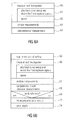
- Fig. 6a illustrates a measurement for each loudspeaker at 60 where the sinus sweep is played back and the seven microphone signals are recorded at 61.
- a pause 62 is then conducted and, subsequently, the measurements are analyzed 63 and saved 64.
- the reference measurements are performed subsequent to a manual verification in that, for the reference measurements, all loudspeakers are correctly adjusted and at the correct position. These reference measurements must be performed only a single time and can be used again and again.
- test measurements should, preferably, be performed before each listening test.
- the complete sequence of test measurements is presented in Fig. 6b .
- control settings are read.
- each loudspeaker is measured by playing back the sinus sweep and by recording the seven microphone signals and the subsequent pause.
- step 67 a measurement analysis is performed and in step 68, the results are compared with the reference measurement.
- step 69 it is determined whether the measured results are inside the tolerance range or not.
- a visional presentation of results can be performed and in step 74, the results can be saved.
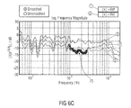
- Fig. 6c illustrates an example for visual presentation of the results in accordance with step 73 of Fig. 6b .
- the tolerance check is realized by setting an upper and lower limit around the reference measurement. The limits are defined as parameters at the beginning of the measurement.
- Fig. 6c visualizes the measurement output regarding the magnitude response.
- Curve 3 is the upper limit of the reference measurement and curve 5 is the lower limit.
- Curve 4 is the current measurement.
- a discrepancy in the midrange frequency is shown, which is visualized in the graphical user interface (GUI) by red markers at 75. This violation of the lower limit is also shown in field 2.
- GUI graphical user interface
- the first loudspeaker characteristic is the distance.
- the distance is calculated using the microphone signal generated by microphone R7.
- the controller 14 of Fig. 1 controls the measurement of the reference signal X and the microphone signal Y of the center microphone R7.
- the transfer function of the microphone signal R7 is calculated, as outlined in step 71.
- a search for the maximum, such as 80 in Fig. 8 of the impulse response calculated in step 71 is performed.
- this time at which the maximum 80 occurs is multiplied by the sound velocity v in order to obtain the distance between the corresponding loudspeaker and the microphone array.
- first length only extends from 0 to the time of the maximum 80 and including this maximum, but not including any early reflections or diffuse reverberations.
- any other synchronization can be performed between the test signal and the response from the microphone, but using a first small portion of the impulse response calculated from the microphone signal of microphone R7 is preferred due to efficiency and accuracy.
- the impulse responses for all seven microphones are calculated, but only a second length of the impulse response, which is longer than the first length, is used and this second length preferably extends only up to the early reflections and, preferably, do not include the early reflections.
- the early reflections are included in the second length in an attenuated state determined by a side portion of a window function, as e.g. illustrated in Fig. 8 by window shape 81.
- the side portion has window coefficients smaller than 0.5 or even smaller than 0.3 compared to window coefficients in the mid portion of the window, which approach 1.0.
- the impulse responses for the individual microphones R1 to R7 are preferably calculated, as indicated by steps 70, 71.
- a window is applied to each impulse response or a microphone signal different from the impulse response, wherein a center of the window or a point of the window within 50 percents of the window length centered around the center of the window is placed at the maximum in each impulse response or a time in the microphone signal corresponding to the maximum to obtain a windowed frame for each sound signal
- the third characteristic for each loudspeaker is calculated using the microphone signal of microphone R5, since this microphone is not influenced too much by the mechanical support of the microphone array illustrated in Fig. 3 .
- the third length of the impulse response is longer than the second length and, preferably, includes not only the early reflections, but also the diffuse reflections and may extend over a considerable amount of time, such as 0.2 ms in order to have all reflections in the listening space.
- the impulse response of microphone R5 will be close to 0 quite earlier.
- aspects have been described in the context of an apparatus, it is clear that these aspects also represent a description of the corresponding method, where a block or device corresponds to a method step or a feature of a method step. Analogously, aspects described in the context of a method step also represent a description of a corresponding block or item or feature of a corresponding apparatus.
- the invention can be implemented in hardware or in software.
- the implementation can be performed using a digital storage medium, for example a floppy disk, a DVD, a CD, a ROM, a PROM, an EPROM, an EEPROM or a FLASH memory, having electronically readable control signals stored thereon, which cooperate (or are capable of cooperating) with a programmable computer system such that the respective method is performed.
- a digital storage medium for example a floppy disk, a DVD, a CD, a ROM, a PROM, an EPROM, an EEPROM or a FLASH memory, having electronically readable control signals stored thereon, which cooperate (or are capable of cooperating) with a programmable computer system such that the respective method is performed.
- Some implementation examples according to the invention comprise a data carrier having electronically readable control signals, which are capable of cooperating with a programmable computer system, such that one of the methods described herein is performed.
- the present invention can be implemented as a computer program product with a program code, the program code being operative for performing one of the methods when the computer program product runs on a computer.
- the program code may for example be stored on a machine readable carrier.
- implementation examples comprise the computer program for performing one of the methods described herein, stored on a machine readable carrier.
- an implementation example of the inventive method is, therefore, a computer program having a program code for performing one of the methods described herein, when the computer program runs on a computer.
- a further implementation example of the inventive methods is, therefore, a data carrier (or a digital storage medium, or a computer-readable medium) comprising, recorded thereon, the computer program for performing one of the methods described herein.
- a further implementation example of the inventive method is, therefore, a data stream or a sequence of signals representing the computer program for performing one of the methods described herein.
- the data stream or the sequence of signals may for example be configured to be transferred via a data communication connection, for example via the Internet.
- a further implementation example comprises a processing means, for example a computer, or a programmable logic device, configured to or adapted to perform one of the methods described herein.
- a further implementation example comprises a computer having installed thereon the computer program for performing one of the methods described herein.
- a programmable logic device for example a field programmable gate array
- a field programmable gate array may cooperate with a microprocessor in order to perform one of the methods described herein.
- the methods are preferably performed by any hardware apparatus.
Landscapes
- Physics & Mathematics (AREA)
- Engineering & Computer Science (AREA)
- Acoustics & Sound (AREA)
- Signal Processing (AREA)
- Health & Medical Sciences (AREA)
- Otolaryngology (AREA)
- General Health & Medical Sciences (AREA)
- Stereophonic System (AREA)
- Circuit For Audible Band Transducer (AREA)
- Measurement Of Mechanical Vibrations Or Ultrasonic Waves (AREA)
- Obtaining Desirable Characteristics In Audible-Bandwidth Transducers (AREA)
Claims (9)
- Appareil permettant de mesurer une pluralité de haut-parleurs disposés à des positions différentes, comprenant:un générateur de signal de test (10) destiné à générer un signal de test pour un haut-parleur;un dispositif de microphones (12) configuré pour recevoir une pluralité de signaux sonores différents en réponse à un ou plusieurs signaux de haut-parleur émis par un haut-parleur de la pluralité de haut-parleurs en réponse au signal de test;un contrôleur (14) destiné à commander les émissions des signaux de haut-parleur par la pluralité de haut-parleurs et à manipuler la pluralité de signaux sonores différents de sorte qu'un ensemble de signaux sonores enregistrés par le dispositif de microphones soit associé à chaque haut-parleur de la pluralité de haut-parleurs en réponse au signal de test; etun évaluateur (16) destiné à évaluer l'ensemble de signaux sonores pour chaque haut-parleur, pour déterminer au moins une caractéristique de haut-parleur pour chaque haut-parleur et à indiquer un état de haut-parleur à l'aide de l'au moins une caractéristique de haut-parleur pour le haut-parleur,dans lequel le dispositif de microphones comprend un réseau de microphones comprenant trois paires de microphones disposées sur trois axes spatiaux;dans lequel l'évaluateur (16) est configuré pour
dériver un signal de pression omnidirectionnel à l'aide des signaux reçus par les trois paires ou à l'aide d'un autre microphone disposé en un point où les trois axes spatiaux viennent en intersection l'un avec l'autre,
calculer une distance entre le réseau de microphones et un haut-parleur sur base d'une première longueur du signal de pression omnidirectionnel, où la première longueur s'étend de 0 au moment du maximum de son direct du signal de pression omnidirectionnel;
calculer une réponse impulsionnelle ou une fonction de transfert du haut-parleur à l'aide d'un signal de microphone d'un microphone individuel des trois paires, le signal de microphone présentant une troisième longueur, la troisième longueur présentant au moins un maximum de son direct et des réflexions précoces, la troisième longueur étant plus longue que la première longueur; et
calculer une direction d'arrivée du son du haut-parleur à l'aide de signaux de tous les microphones, les signaux présentant une deuxième longueur plus longue que la première longueur et plus courte que la troisième longueur, la deuxième longueur comportant des valeurs allant jusqu'à une réflexion précoce, de sorte que les réflexions précoces ne soient pas incluses dans la deuxième longueur ou soient incluses dans la deuxième longueur dans un état atténué déterminé par une partie latérale d'une fonction de fenêtre. - Appareil selon la revendication 1, dans lequel le contrôleur (14) est configuré pour commander automatiquement le générateur de signal de test (10) et le dispositif de microphones (12) pour générer les signaux de test de manière séquentielle et pour recevoir les signaux sonores de manière séquentielle, de sorte que l'ensemble de signaux sonores soit associé au haut-parleur spécifique qui a émis le signal de test de haut-parleur immédiatement avant une réception de l'ensemble de signaux sonores, ou
dans lequel le contrôleur (14) est configuré pour commander automatiquement le générateur de signal de test (10) et le dispositif de microphones (12) pour générer les signaux de test en parallèle et pour démultiplexer les signaux sonores de sorte que l'ensemble de signaux sonores soit associé au haut-parleur spécifique qui est associé à une certaine bande de fréquences de l'ensemble de signaux sonores ou qui est associé à une certaine séquence de codes dans un signal de test multiplexé par code. - Appareil selon la revendication 1 ou 2, dans lequel l'évaluateur (16) est configuré pour calculer une distance entre la position de haut-parleur pour un haut-parleur et le dispositif de microphones à l'aide d'une valeur de retard dans le temps d'un maximum d'une réponse impulsionnelle d'un signal sonore entre le haut-parleur et le dispositif de microphones et à l'aide de la vitesse du son dans l'air.
- Appareil selon l'une des revendications précédentes, dans lequel le contrôleur (14) est configuré pour effectuer une mesure de référence à l'aide du signal de test (70), où une sortie analogique d'un convertisseur numérique/analogique (51) vers un haut-parleur et une entrée analogique d'un convertisseur analogique/numérique (52) auquel est connecté le dispositif de microphones sont connectées directement pour déterminer les données de mesure de référence; et
dans lequel l'évaluateur (16) est configuré pour déterminer une fonction de transfert ou une réponse impulsionnelle pour un microphone sélectionné d'une pluralité de microphones du dispositif de microphones à l'aide des données de mesure de référence, pour déterminer une réponse impulsionnelle ou une fonction de transfert pour le haut-parleur comme caractéristique de haut-parleur. - Appareil selon l'une des revendications précédentes,
dans lequel l'évaluateur (16) est configuré pour calculer une direction d'arrivée pour le son émis par un haut-parleur à l'aide de l'ensemble de signaux sonores, dans lequel l'évaluateur est adapté pour
transformer (40) l'ensemble de signaux de test en signaux de format B présentant un signal omnidirectionnel (W) et au moins deux signaux de vitesse de particules (X, Y, Z) pour au moins deux directions orthogonales dans l'espace;
calculer, pour chaque bin de fréquences d'une pluralité de bins de fréquences, un résultat de direction d'arrivée; et
déterminer (46, 47) la direction d'arrivée pour le son émis par le haut-parleur à l'aide des résultats de direction d'arrivée pour la pluralité de bins de fréquences. - Appareil selon la revendication 5, dans lequel l'évaluateur (16) est configuré pour calculer une réponse impulsionnelle pour chaque microphone,
pour rechercher un maximum dans chaque réponse impulsionnelle;
pour appliquer une fenêtre à chaque réponse impulsionnelle ou un signal de microphone différent de la réponse impulsionnelle, où un centre de la fenêtre ou un point de la fenêtre dans une plage de 50 pourcent de la longueur de la fenêtre centré autour du centre de la fenêtre est placé au maximum dans chaque réponse impulsionnelle ou un moment dans le signal de microphone correspondant au maximum, pour obtenir une trame divisée en fenêtres pour chaque signal sonore; et
pour convertir chaque trame du domaine temporel à un domaine spectral. - Appareil selon la revendication 5, dans lequel l'évaluateur (16) est configuré pour déterminer la direction d'arrivée en calculant une densité d'énergie spatiale réelle présentant une valeur pour chaque angle d'élévation et pour chaque angle d'azimut, et
pour fournir une pluralité de densités d'énergie spatiales théoriques en supposant un bruit de microphone gaussien blanc moyen zéro pour différents angles d'élévation et angles d'azimut, et
pour sélectionner (47) l'angle d'élévation et l'angle d'azimut appartenant à la densité d'énergie spatiale idéal qui est le mieux adapté à la densité d'énergie spatiale réelle. - Appareil selon l'une des revendications précédentes, dans lequel l'évaluateur est configuré pour comparer l'au moins une caractéristique de haut-parleur avec une caractéristique de haut-parleur prévue et pour indiquer un haut-parleur présentant au moins une caractéristique de haut-parleur égale à la caractéristique de haut-parleur prévue comme haut-parleur fonctionnel et pour indiquer un haut-parleur qui ne présente pas l'au moins une caractéristique de haut-parleur égale à la caractéristique de haut-parleur prévue comme haut-parleur non fonctionnel.
- Procédé permettant de mesurer une pluralité de haut-parleurs disposés à des positions différentes dans un espace d'écoute, comprenant le fait de:générer (10) un signal de test pour un haut-parleur;recevoir une pluralité de signaux sonores différents par un dispositif de microphones en réponse à un ou plusieurs signaux de haut-parleur émis par un haut-parleur de la pluralité de haut-parleurs en réponse au signal de test;commander (14) les émissions des signaux de haut-parleur par la pluralité de haut-parleurs et manipuler la pluralité de signaux sonores différents de sorte qu'un ensemble de signaux sonores enregistrés par le dispositif de microphones soit associé à chaque haut-parleur de la pluralité de haut-parleurs en réponse au signal de test; etévaluer (16) l'ensemble de signaux sonores pour chaque haut-parleur, pour déterminer au moins une caractéristique de haut-parleur pour chaque haut-parleur et indiquer un état de haut-parleur à l'aide de l'au moins une caractéristique de haut-parleur pour le haut-parleur,dans lequel le dispositif de microphones comprend un réseau de microphones comprenant trois paires de microphones disposés sur trois axes spatiaux;dans lequel le fait d'évaluer (16) comprend le fait de:dériver un signal de pression omnidirectionnel à l'aide des signaux reçus par les trois paires ou à l'aide d'un autre microphone disposé à un point où les trois axes spatiaux viennent en intersection l'un avec l'autre,calculer une distance entre le réseau de microphones et un haut-parleur sur base d'une première longueur du signal de pression omnidirectionnel, où la première longueur s'étend de 0 au moment du maximum du son direct du signal de pression omnidirectionnel;calculer une réponse impulsionnelle ou une fonction de transfert du haut-parleur à l'aide d'un signal de microphone d'un microphone individuel des trois paires, le signal de microphone présentant une troisième longueur, la troisième longueur présentant au moins un maximal de son direct et des réflexions précoces, la troisième longueur étant plus longue que la première longueur; etcalculer une direction d'arrivée du son du haut-parleur à l'aide de signaux de tous les microphones, les signaux présentant une deuxième longueur plus longue que la première longueur et plus courte que la troisième longueur, la deuxième longueur comportant des valeurs allant jusqu'à une réflexion précoce, de sorte que les réflexions précoces ne soient pas incluses dans la deuxième longueur ou soient incluses dans la deuxième longueur dans un état atténué déterminé par une partie latérale d'une fonction de fenêtre.
Priority Applications (2)
| Application Number | Priority Date | Filing Date | Title |
|---|---|---|---|
| PL13197826T PL2731353T3 (pl) | 2010-03-31 | 2011-03-30 | Urządzenie i sposób do pomiaru wielu głośników |
| EP13197826.4A EP2731353B1 (fr) | 2010-03-31 | 2011-03-30 | Appareil et procédé permettant de mesurer une pluralité de haut-parleurs |
Applications Claiming Priority (4)
| Application Number | Priority Date | Filing Date | Title |
|---|---|---|---|
| US31971210P | 2010-03-31 | 2010-03-31 | |
| EP10159914A EP2375779A3 (fr) | 2010-03-31 | 2010-04-14 | Appareil et procédé de mesure d'une pluralité de haut-parleurs et réseau de microphones |
| EP11711335.7A EP2553942B1 (fr) | 2010-03-31 | 2011-03-30 | Appareil et procédé de mesure d'une pluralité de haut-parleurs et réseau de microphones |
| EP13197826.4A EP2731353B1 (fr) | 2010-03-31 | 2011-03-30 | Appareil et procédé permettant de mesurer une pluralité de haut-parleurs |
Related Parent Applications (2)
| Application Number | Title | Priority Date | Filing Date |
|---|---|---|---|
| EP11711335.7A Division EP2553942B1 (fr) | 2010-03-31 | 2011-03-30 | Appareil et procédé de mesure d'une pluralité de haut-parleurs et réseau de microphones |
| EP11711335.7A Division-Into EP2553942B1 (fr) | 2010-03-31 | 2011-03-30 | Appareil et procédé de mesure d'une pluralité de haut-parleurs et réseau de microphones |
Publications (3)
| Publication Number | Publication Date |
|---|---|
| EP2731353A2 EP2731353A2 (fr) | 2014-05-14 |
| EP2731353A3 EP2731353A3 (fr) | 2014-07-30 |
| EP2731353B1 true EP2731353B1 (fr) | 2015-09-09 |
Family
ID=44211760
Family Applications (3)
| Application Number | Title | Priority Date | Filing Date |
|---|---|---|---|
| EP10159914A Withdrawn EP2375779A3 (fr) | 2010-03-31 | 2010-04-14 | Appareil et procédé de mesure d'une pluralité de haut-parleurs et réseau de microphones |
| EP11711335.7A Active EP2553942B1 (fr) | 2010-03-31 | 2011-03-30 | Appareil et procédé de mesure d'une pluralité de haut-parleurs et réseau de microphones |
| EP13197826.4A Active EP2731353B1 (fr) | 2010-03-31 | 2011-03-30 | Appareil et procédé permettant de mesurer une pluralité de haut-parleurs |
Family Applications Before (2)
| Application Number | Title | Priority Date | Filing Date |
|---|---|---|---|
| EP10159914A Withdrawn EP2375779A3 (fr) | 2010-03-31 | 2010-04-14 | Appareil et procédé de mesure d'une pluralité de haut-parleurs et réseau de microphones |
| EP11711335.7A Active EP2553942B1 (fr) | 2010-03-31 | 2011-03-30 | Appareil et procédé de mesure d'une pluralité de haut-parleurs et réseau de microphones |
Country Status (12)
| Country | Link |
|---|---|
| US (2) | US9215542B2 (fr) |
| EP (3) | EP2375779A3 (fr) |
| JP (2) | JP5659291B2 (fr) |
| KR (2) | KR101489046B1 (fr) |
| CN (2) | CN104602166B (fr) |
| AU (2) | AU2011234505B2 (fr) |
| CA (2) | CA2795005C (fr) |
| ES (2) | ES2463395T3 (fr) |
| MX (1) | MX2012011242A (fr) |
| PL (2) | PL2553942T3 (fr) |
| RU (1) | RU2616345C2 (fr) |
| WO (1) | WO2011121004A2 (fr) |
Families Citing this family (166)
| Publication number | Priority date | Publication date | Assignee | Title |
|---|---|---|---|---|
| US20110123054A1 (en) * | 2009-11-19 | 2011-05-26 | Adamson Systems Engineering Inc. | Method and system for determining relative positions of multiple loudspeakers in a space |
| EP2600637A1 (fr) * | 2011-12-02 | 2013-06-05 | Fraunhofer-Gesellschaft zur Förderung der angewandten Forschung e.V. | Appareil et procédé pour le positionnement de microphone en fonction de la densité spatiale de puissance |
| FR2984670A1 (fr) * | 2011-12-15 | 2013-06-21 | Peugeot Citroen Automobiles Sa | Dispositif et procede de test d'un systeme audio comportant des sous-ensembles de haut-parleurs, par generation de groupes de sons specifiques |
| JP2013247456A (ja) * | 2012-05-24 | 2013-12-09 | Toshiba Corp | 音響処理装置、音響処理方法、音響処理プログラムおよび音響処理システム |
| WO2013190632A1 (fr) * | 2012-06-19 | 2013-12-27 | Toa株式会社 | Dispositif de haut-parleur |
| CN102857852B (zh) * | 2012-09-12 | 2014-10-22 | 清华大学 | 一种声场定量重现控制系统的扬声器回放阵列控制信号的处理方法 |
| US9609141B2 (en) * | 2012-10-26 | 2017-03-28 | Avago Technologies General Ip (Singapore) Pte. Ltd. | Loudspeaker localization with a microphone array |
| EP2747451A1 (fr) * | 2012-12-21 | 2014-06-25 | Fraunhofer-Gesellschaft zur Förderung der angewandten Forschung e.V. | Filtre et procédé de filtrage spatial informé utilisant de multiples estimations instantanées de direction d'arrivée |
| BR112015020150B1 (pt) * | 2013-02-26 | 2021-08-17 | Mediatek Inc. | Aparelho para gerar um sinal de fala, e, método para gerar um sinal de fala |
| WO2014138300A1 (fr) * | 2013-03-06 | 2014-09-12 | Tiskerling Dynamics Llc | Système et procédé de mesure simultanée robuste d'un circuit d'attaque pour un système de haut-parleurs |
| US9357306B2 (en) | 2013-03-12 | 2016-05-31 | Nokia Technologies Oy | Multichannel audio calibration method and apparatus |
| US10750132B2 (en) * | 2013-03-14 | 2020-08-18 | Pelco, Inc. | System and method for audio source localization using multiple audio sensors |
| US9961472B2 (en) * | 2013-03-14 | 2018-05-01 | Apple Inc. | Acoustic beacon for broadcasting the orientation of a device |
| WO2014147551A1 (fr) * | 2013-03-19 | 2014-09-25 | Koninklijke Philips N.V. | Procédé et appareil de détermination d'une position d'un microphone |
| CN104982042B (zh) | 2013-04-19 | 2018-06-08 | 韩国电子通信研究院 | 多信道音频信号处理装置及方法 |
| WO2014171791A1 (fr) | 2013-04-19 | 2014-10-23 | 한국전자통신연구원 | Appareil et procédé de traitement de signal audio multicanal |
| CN103414991B (zh) * | 2013-05-21 | 2016-07-06 | 杭州联汇数字科技有限公司 | 一种室内扩声系统自适应调整方法 |
| CN103414990B (zh) * | 2013-05-21 | 2016-02-10 | 杭州联汇数字科技有限公司 | 室内扩声设备检测方法 |
| US9319819B2 (en) * | 2013-07-25 | 2016-04-19 | Etri | Binaural rendering method and apparatus for decoding multi channel audio |
| CN104581603A (zh) * | 2013-10-09 | 2015-04-29 | 纬创资通股份有限公司 | 自动测试系统及测试辅助装置 |
| NL2011583C2 (en) * | 2013-10-10 | 2015-04-13 | Wwinn B V | Module, system and method for detecting acoustical failure of a sound source. |
| DE102013223201B3 (de) * | 2013-11-14 | 2015-05-13 | Fraunhofer-Gesellschaft zur Förderung der angewandten Forschung e.V. | Verfahren und Vorrichtung zum Komprimieren und Dekomprimieren von Schallfelddaten eines Gebietes |
| CN103702259B (zh) | 2013-12-31 | 2017-12-12 | 北京智谷睿拓技术服务有限公司 | 交互装置及交互方法 |
| CN103747409B (zh) * | 2013-12-31 | 2017-02-08 | 北京智谷睿拓技术服务有限公司 | 扬声装置、扬声方法及交互设备 |
| US10477337B2 (en) | 2014-01-16 | 2019-11-12 | Sony Corporation | Audio processing device and method therefor |
| KR102197230B1 (ko) * | 2014-10-06 | 2020-12-31 | 한국전자통신연구원 | 음향 특성을 예측하는 오디오 시스템 및 방법 |
| EP3826324B1 (fr) * | 2015-05-15 | 2025-08-20 | Nureva Inc. | Système et procédé pour incorporer des informations supplémentaires dans un signal de bruit de masque sonore |
| KR102340202B1 (ko) | 2015-06-25 | 2021-12-17 | 한국전자통신연구원 | 실내의 반사 특성을 추출하는 오디오 시스템 및 방법 |
| WO2017052550A1 (fr) * | 2015-09-24 | 2017-03-30 | Intel Corporation | Identification de bruit de plate-forme à l'aide d'un microphone intégré dans une plate-forme |
| TWI567407B (zh) * | 2015-09-25 | 2017-01-21 | 國立清華大學 | 電子裝置及電子裝置之操作方法 |
| JP6546698B2 (ja) * | 2015-09-25 | 2019-07-17 | フラウンホーファー−ゲゼルシャフト ツル フェルデルング デル アンゲヴァンテン フォルシュング エー ファウFraunhofer−Gesellschaft zur Foerderung der angewandten Forschung e.V. | レンダリングシステム |
| WO2017061023A1 (fr) * | 2015-10-09 | 2017-04-13 | 株式会社日立製作所 | Procédé et dispositif de traitement de signal audio |
| US10206040B2 (en) * | 2015-10-30 | 2019-02-12 | Essential Products, Inc. | Microphone array for generating virtual sound field |
| US20190158970A1 (en) * | 2015-12-25 | 2019-05-23 | Panasonic Intellectual Property Management Co., Ltd. | Sound reproduction device |
| US9820039B2 (en) | 2016-02-22 | 2017-11-14 | Sonos, Inc. | Default playback devices |
| US10264030B2 (en) | 2016-02-22 | 2019-04-16 | Sonos, Inc. | Networked microphone device control |
| US9947316B2 (en) | 2016-02-22 | 2018-04-17 | Sonos, Inc. | Voice control of a media playback system |
| US10142754B2 (en) | 2016-02-22 | 2018-11-27 | Sonos, Inc. | Sensor on moving component of transducer |
| US10095470B2 (en) | 2016-02-22 | 2018-10-09 | Sonos, Inc. | Audio response playback |
| US9811314B2 (en) | 2016-02-22 | 2017-11-07 | Sonos, Inc. | Metadata exchange involving a networked playback system and a networked microphone system |
| US9965247B2 (en) | 2016-02-22 | 2018-05-08 | Sonos, Inc. | Voice controlled media playback system based on user profile |
| JP6493245B2 (ja) * | 2016-02-24 | 2019-04-03 | オンキヨー株式会社 | 音場制御システム、解析装置、音響装置、音場制御システムの制御方法、解析装置の制御方法、音響装置の制御方法、プログラム、記録媒体 |
| JP6668139B2 (ja) * | 2016-03-29 | 2020-03-18 | 本田技研工業株式会社 | 検査装置および検査方法 |
| JP6361680B2 (ja) * | 2016-03-30 | 2018-07-25 | オンキヨー株式会社 | 音場制御システム、解析装置、音響装置、音場制御システムの制御方法、解析装置の制御方法、音響装置の制御方法、プログラム、記録媒体 |
| GB2549532A (en) | 2016-04-22 | 2017-10-25 | Nokia Technologies Oy | Merging audio signals with spatial metadata |
| JP6620675B2 (ja) * | 2016-05-27 | 2019-12-18 | パナソニックIpマネジメント株式会社 | 音声処理システム、音声処理装置及び音声処理方法 |
| US9978390B2 (en) | 2016-06-09 | 2018-05-22 | Sonos, Inc. | Dynamic player selection for audio signal processing |
| CN106131754B (zh) * | 2016-06-30 | 2018-06-29 | 广东美的制冷设备有限公司 | 多设备之间的分组方法和装置 |
| US10134399B2 (en) | 2016-07-15 | 2018-11-20 | Sonos, Inc. | Contextualization of voice inputs |
| US10152969B2 (en) | 2016-07-15 | 2018-12-11 | Sonos, Inc. | Voice detection by multiple devices |
| US10115400B2 (en) | 2016-08-05 | 2018-10-30 | Sonos, Inc. | Multiple voice services |
| CN107782441B (zh) * | 2016-08-30 | 2021-04-13 | 张若愚 | 一种用于目标噪声测试的三维声学传感器阵列 |
| US9794720B1 (en) * | 2016-09-22 | 2017-10-17 | Sonos, Inc. | Acoustic position measurement |
| US9942678B1 (en) | 2016-09-27 | 2018-04-10 | Sonos, Inc. | Audio playback settings for voice interaction |
| EP4235207B1 (fr) * | 2016-09-29 | 2026-01-28 | Dolby Laboratories Licensing Corporation | Découverte et localisation automatiques d'emplacements de haut-parleur dans des systèmes de sons d'ambiance |
| US9743204B1 (en) | 2016-09-30 | 2017-08-22 | Sonos, Inc. | Multi-orientation playback device microphones |
| US10181323B2 (en) | 2016-10-19 | 2019-01-15 | Sonos, Inc. | Arbitration-based voice recognition |
| GB2555139A (en) * | 2016-10-21 | 2018-04-25 | Nokia Technologies Oy | Detecting the presence of wind noise |
| US10375498B2 (en) | 2016-11-16 | 2019-08-06 | Dts, Inc. | Graphical user interface for calibrating a surround sound system |
| CN106792415B (zh) * | 2016-12-26 | 2019-11-15 | 歌尔科技有限公司 | 一种用于数字麦克风阵列的测试方法及装置 |
| JP6666276B2 (ja) * | 2017-01-23 | 2020-03-13 | 日本電信電話株式会社 | 音声信号変換装置、その方法、及びプログラム |
| JP6788272B2 (ja) * | 2017-02-21 | 2020-11-25 | オンフューチャー株式会社 | 音源の検出方法及びその検出装置 |
| WO2018157098A1 (fr) * | 2017-02-27 | 2018-08-30 | Essential Products, Inc. | Réseau de microphones servant à générer un champ sonore virtuel |
| EP3606101B1 (fr) * | 2017-03-22 | 2025-02-19 | Yamaha Corporation | Dispositif de traitement de signal |
| US11183181B2 (en) | 2017-03-27 | 2021-11-23 | Sonos, Inc. | Systems and methods of multiple voice services |
| US10531196B2 (en) * | 2017-06-02 | 2020-01-07 | Apple Inc. | Spatially ducking audio produced through a beamforming loudspeaker array |
| US10334360B2 (en) * | 2017-06-12 | 2019-06-25 | Revolabs, Inc | Method for accurately calculating the direction of arrival of sound at a microphone array |
| CN107635184A (zh) * | 2017-08-04 | 2018-01-26 | 王路明 | 一种多功能扬声器的测试装置 |
| US10475449B2 (en) | 2017-08-07 | 2019-11-12 | Sonos, Inc. | Wake-word detection suppression |
| US10425759B2 (en) * | 2017-08-30 | 2019-09-24 | Harman International Industries, Incorporated | Measurement and calibration of a networked loudspeaker system |
| US10412532B2 (en) | 2017-08-30 | 2019-09-10 | Harman International Industries, Incorporated | Environment discovery via time-synchronized networked loudspeakers |
| US10048930B1 (en) | 2017-09-08 | 2018-08-14 | Sonos, Inc. | Dynamic computation of system response volume |
| US10446165B2 (en) | 2017-09-27 | 2019-10-15 | Sonos, Inc. | Robust short-time fourier transform acoustic echo cancellation during audio playback |
| US10621981B2 (en) | 2017-09-28 | 2020-04-14 | Sonos, Inc. | Tone interference cancellation |
| US10482868B2 (en) | 2017-09-28 | 2019-11-19 | Sonos, Inc. | Multi-channel acoustic echo cancellation |
| US10051366B1 (en) | 2017-09-28 | 2018-08-14 | Sonos, Inc. | Three-dimensional beam forming with a microphone array |
| US10466962B2 (en) | 2017-09-29 | 2019-11-05 | Sonos, Inc. | Media playback system with voice assistance |
| US10665234B2 (en) * | 2017-10-18 | 2020-05-26 | Motorola Mobility Llc | Detecting audio trigger phrases for a voice recognition session |
| JP6742535B2 (ja) * | 2017-11-15 | 2020-08-19 | 三菱電機株式会社 | 収音再生装置並びにプログラム及び記録媒体 |
| US10880650B2 (en) | 2017-12-10 | 2020-12-29 | Sonos, Inc. | Network microphone devices with automatic do not disturb actuation capabilities |
| US10818290B2 (en) | 2017-12-11 | 2020-10-27 | Sonos, Inc. | Home graph |
| US11343614B2 (en) | 2018-01-31 | 2022-05-24 | Sonos, Inc. | Device designation of playback and network microphone device arrangements |
| CN108430026B (zh) * | 2018-03-07 | 2020-08-21 | 广州艾美网络科技有限公司 | 音频设备故障检测方法和点唱设备 |
| JP7000926B2 (ja) * | 2018-03-08 | 2022-01-19 | ヤマハ株式会社 | スピーカの接続状態判定システム、音響装置及びスピーカの接続状態判定方法 |
| JP7020203B2 (ja) * | 2018-03-13 | 2022-02-16 | 株式会社竹中工務店 | アンビソニックス信号生成装置、音場再生装置、及びアンビソニックス信号生成方法 |
| JP6999232B2 (ja) * | 2018-03-18 | 2022-01-18 | アルパイン株式会社 | 音響特性測定装置および方法 |
| US11175880B2 (en) | 2018-05-10 | 2021-11-16 | Sonos, Inc. | Systems and methods for voice-assisted media content selection |
| US10847178B2 (en) | 2018-05-18 | 2020-11-24 | Sonos, Inc. | Linear filtering for noise-suppressed speech detection |
| US10959029B2 (en) | 2018-05-25 | 2021-03-23 | Sonos, Inc. | Determining and adapting to changes in microphone performance of playback devices |
| US10841717B2 (en) | 2018-06-21 | 2020-11-17 | Meyer Sound Laboratories, Incorporated | Signal generator and method for measuring the performance of a loudspeaker |
| US10681460B2 (en) | 2018-06-28 | 2020-06-09 | Sonos, Inc. | Systems and methods for associating playback devices with voice assistant services |
| US10461710B1 (en) | 2018-08-28 | 2019-10-29 | Sonos, Inc. | Media playback system with maximum volume setting |
| US11076035B2 (en) | 2018-08-28 | 2021-07-27 | Sonos, Inc. | Do not disturb feature for audio notifications |
| CN109379687B (zh) * | 2018-09-03 | 2020-08-14 | 华南理工大学 | 一种线阵列扬声器系统垂直指向性的测量和推算方法 |
| US10878811B2 (en) | 2018-09-14 | 2020-12-29 | Sonos, Inc. | Networked devices, systems, and methods for intelligently deactivating wake-word engines |
| US10587430B1 (en) | 2018-09-14 | 2020-03-10 | Sonos, Inc. | Networked devices, systems, and methods for associating playback devices based on sound codes |
| US11024331B2 (en) | 2018-09-21 | 2021-06-01 | Sonos, Inc. | Voice detection optimization using sound metadata |
| US10811015B2 (en) | 2018-09-25 | 2020-10-20 | Sonos, Inc. | Voice detection optimization based on selected voice assistant service |
| US11100923B2 (en) | 2018-09-28 | 2021-08-24 | Sonos, Inc. | Systems and methods for selective wake word detection using neural network models |
| US10692518B2 (en) | 2018-09-29 | 2020-06-23 | Sonos, Inc. | Linear filtering for noise-suppressed speech detection via multiple network microphone devices |
| US11184725B2 (en) | 2018-10-09 | 2021-11-23 | Samsung Electronics Co., Ltd. | Method and system for autonomous boundary detection for speakers |
| CN109040911B (zh) * | 2018-10-12 | 2021-09-17 | 上海摩软通讯技术有限公司 | 智能音箱及其目标放置位置的确定方法 |
| US11899519B2 (en) | 2018-10-23 | 2024-02-13 | Sonos, Inc. | Multiple stage network microphone device with reduced power consumption and processing load |
| EP3654249A1 (fr) | 2018-11-15 | 2020-05-20 | Snips | Convolutions dilatées et déclenchement efficace de mot-clé |
| DE102019132544B4 (de) | 2018-12-04 | 2023-04-27 | Harman International Industries, Incorporated | Umgebungserkennung über zeitsynchronisierte vernetzte lautsprecher |
| US11183183B2 (en) | 2018-12-07 | 2021-11-23 | Sonos, Inc. | Systems and methods of operating media playback systems having multiple voice assistant services |
| US11132989B2 (en) | 2018-12-13 | 2021-09-28 | Sonos, Inc. | Networked microphone devices, systems, and methods of localized arbitration |
| DE102018221795B4 (de) * | 2018-12-14 | 2025-03-13 | Volkswagen Aktiengesellschaft | Vorrichtung zur Erzeugung eines haptisch wahrnehmbaren Bereiches sowie Konfigurations- und Steuerverfahren einer solchen Vorrichtung |
| BE1026885B1 (nl) * | 2018-12-18 | 2020-07-22 | Soundtalks Nv | Inrichting voor het monitoren van de status van een veeteeltfaciliteit |
| CN109671439B (zh) * | 2018-12-19 | 2024-01-19 | 成都大学 | 一种智能化果林鸟害防治设备及其鸟类定位方法 |
| RU2716556C1 (ru) * | 2018-12-19 | 2020-03-12 | Общество с ограниченной ответственностью "ПРОМОБОТ" | Способ приема речевых сигналов |
| US10602268B1 (en) | 2018-12-20 | 2020-03-24 | Sonos, Inc. | Optimization of network microphone devices using noise classification |
| CN109511075B (zh) * | 2018-12-24 | 2020-11-17 | 科大讯飞股份有限公司 | 一种用于测量麦克风阵列声学响应的系统 |
| CN109618273B (zh) * | 2018-12-29 | 2020-08-04 | 北京声智科技有限公司 | 麦克风质检的装置及方法 |
| US10791411B2 (en) * | 2019-01-10 | 2020-09-29 | Qualcomm Incorporated | Enabling a user to obtain a suitable head-related transfer function profile |
| US11315556B2 (en) | 2019-02-08 | 2022-04-26 | Sonos, Inc. | Devices, systems, and methods for distributed voice processing by transmitting sound data associated with a wake word to an appropriate device for identification |
| US10867604B2 (en) | 2019-02-08 | 2020-12-15 | Sonos, Inc. | Devices, systems, and methods for distributed voice processing |
| US11120794B2 (en) | 2019-05-03 | 2021-09-14 | Sonos, Inc. | Voice assistant persistence across multiple network microphone devices |
| CN110049424B (zh) * | 2019-05-16 | 2021-02-02 | 苏州静声泰科技有限公司 | 一种基于检测gil故障声的麦克风阵列无线校准方法 |
| US11361756B2 (en) | 2019-06-12 | 2022-06-14 | Sonos, Inc. | Conditional wake word eventing based on environment |
| US11200894B2 (en) | 2019-06-12 | 2021-12-14 | Sonos, Inc. | Network microphone device with command keyword eventing |
| US10586540B1 (en) | 2019-06-12 | 2020-03-10 | Sonos, Inc. | Network microphone device with command keyword conditioning |
| US11138975B2 (en) | 2019-07-31 | 2021-10-05 | Sonos, Inc. | Locally distributed keyword detection |
| US10871943B1 (en) | 2019-07-31 | 2020-12-22 | Sonos, Inc. | Noise classification for event detection |
| US11138969B2 (en) | 2019-07-31 | 2021-10-05 | Sonos, Inc. | Locally distributed keyword detection |
| EP4014515B1 (fr) * | 2019-08-14 | 2023-09-27 | Dolby Laboratories Licensing Corporation | Procédé et système pour surveiller et signaler la santé d'un locuteur |
| WO2021051377A1 (fr) | 2019-09-20 | 2021-03-25 | Harman International Industries, Incorporated | Étalonnage de pièce basé sur la distribution gaussienne et l'algorithme des k plus proches voisins |
| US11189286B2 (en) | 2019-10-22 | 2021-11-30 | Sonos, Inc. | VAS toggle based on device orientation |
| CN110767247B (zh) * | 2019-10-29 | 2021-02-19 | 支付宝(杭州)信息技术有限公司 | 语音信号处理方法、声音采集装置和电子设备 |
| US11271607B2 (en) | 2019-11-06 | 2022-03-08 | Rohde & Schwarz Gmbh & Co. Kg | Test system and method for testing a transmission path of a cable connection between a first and a second position |
| US11200900B2 (en) | 2019-12-20 | 2021-12-14 | Sonos, Inc. | Offline voice control |
| WO2021136605A1 (fr) * | 2019-12-30 | 2021-07-08 | Harman Becker Automotive Systems Gmbh | Procédé de réalisation de mesures acoustiques |
| KR102304815B1 (ko) * | 2020-01-06 | 2021-09-23 | 엘지전자 주식회사 | 오디오 장치 및 그의 동작방법 |
| US11562740B2 (en) | 2020-01-07 | 2023-01-24 | Sonos, Inc. | Voice verification for media playback |
| US11556307B2 (en) | 2020-01-31 | 2023-01-17 | Sonos, Inc. | Local voice data processing |
| US11308958B2 (en) | 2020-02-07 | 2022-04-19 | Sonos, Inc. | Localized wakeword verification |
| CN111510841A (zh) * | 2020-04-17 | 2020-08-07 | 上海闻泰电子科技有限公司 | 一种音频部件的检测方法、装置及电子设备 |
| US11727919B2 (en) | 2020-05-20 | 2023-08-15 | Sonos, Inc. | Memory allocation for keyword spotting engines |
| US11482224B2 (en) | 2020-05-20 | 2022-10-25 | Sonos, Inc. | Command keywords with input detection windowing |
| US11308962B2 (en) | 2020-05-20 | 2022-04-19 | Sonos, Inc. | Input detection windowing |
| US12387716B2 (en) | 2020-06-08 | 2025-08-12 | Sonos, Inc. | Wakewordless voice quickstarts |
| JP7444722B2 (ja) * | 2020-07-15 | 2024-03-06 | 日本放送協会 | 音場再現装置及びプログラム |
| CN111935596A (zh) * | 2020-08-14 | 2020-11-13 | 西安艾科特声学科技有限公司 | 一种舱室噪声声场重构系统 |
| US11698771B2 (en) | 2020-08-25 | 2023-07-11 | Sonos, Inc. | Vocal guidance engines for playback devices |
| US11202146B1 (en) * | 2020-09-03 | 2021-12-14 | Algo Communication Products Ltd. | IP speaker system |
| US12283269B2 (en) | 2020-10-16 | 2025-04-22 | Sonos, Inc. | Intent inference in audiovisual communication sessions |
| KR20220057335A (ko) * | 2020-10-29 | 2022-05-09 | 삼성전자주식회사 | 전자 장치 및 그 제어 방법 |
| US11984123B2 (en) | 2020-11-12 | 2024-05-14 | Sonos, Inc. | Network device interaction by range |
| CN114520946B (zh) * | 2020-11-19 | 2024-11-15 | 阿里巴巴集团控股有限公司 | 麦克风阵列检测方法、装置及设备 |
| EP4256372B1 (fr) | 2020-12-01 | 2026-04-08 | Shure Acquisition Holdings, Inc. | Système de mesure de distance acoustique |
| JP7826314B2 (ja) | 2020-12-03 | 2026-03-09 | ドルビー ラボラトリーズ ライセンシング コーポレイション | パーベイシブリスニング向けに編成されたギャップ |
| WO2022119990A1 (fr) | 2020-12-03 | 2022-06-09 | Dolby Laboratories Licensing Corporation | Audibilité au niveau d'un emplacement d'utilisateur par l'intermédiaire d'une audibilité mutuelle de dispositifs |
| WO2022154802A1 (fr) * | 2021-01-15 | 2022-07-21 | Harman International Industries, Incorporated | Système sonore à étalonnage automatique basse fréquence |
| US11551700B2 (en) | 2021-01-25 | 2023-01-10 | Sonos, Inc. | Systems and methods for power-efficient keyword detection |
| US11368804B1 (en) * | 2021-03-24 | 2022-06-21 | xMEMS Labs, Inc. | Testing apparatus and testing method thereof |
| US11792594B2 (en) | 2021-07-29 | 2023-10-17 | Samsung Electronics Co., Ltd. | Simultaneous deconvolution of loudspeaker-room impulse responses with linearly-optimal techniques |
| CN113709648A (zh) * | 2021-08-27 | 2021-11-26 | 重庆紫光华山智安科技有限公司 | 一种麦克风扬声器协同测试方法、系统、介质及电子终端 |
| WO2023056026A1 (fr) | 2021-09-30 | 2023-04-06 | Sonos, Inc. | Activation et désactivation de microphones et d'assistants vocaux |
| WO2023097377A1 (fr) * | 2021-12-03 | 2023-06-08 | 3Ds Mike Pty Ltd | Système d'analyse de son 3d |
| US12327549B2 (en) | 2022-02-09 | 2025-06-10 | Sonos, Inc. | Gatekeeping for voice intent processing |
| CN114630167B (zh) * | 2022-03-07 | 2023-04-25 | 歌尔智能科技有限公司 | 遥控器和电子系统 |
| WO2023177616A1 (fr) * | 2022-03-18 | 2023-09-21 | Sri International | Calibrage rapide de réseaux comprenant de multiples haut-parleurs |
| WO2023245014A2 (fr) * | 2022-06-13 | 2023-12-21 | Sonos, Inc. | Systèmes et procédés pour radar à ulb multi-statique |
| CN115412790B (zh) * | 2022-08-24 | 2024-05-28 | 青岛理工大学 | 一种任意型小孔径平面麦克风阵列布置装置 |
| US12462102B2 (en) | 2022-10-03 | 2025-11-04 | Samsung Electronics Co., Ltd. | Deep learning for multimedia classification |
| CN116506785B (zh) * | 2023-05-04 | 2023-10-20 | 松川国际电子(广东)有限公司 | 一种封闭空间自动调音系统 |
Family Cites Families (31)
| Publication number | Priority date | Publication date | Assignee | Title |
|---|---|---|---|---|
| US4742548A (en) * | 1984-12-20 | 1988-05-03 | American Telephone And Telegraph Company | Unidirectional second order gradient microphone |
| SU1564737A2 (ru) * | 1987-06-15 | 1990-05-15 | Кировоградский Завод Радиоизделий | Устройство дл контрол пол рности электроакустических преобразователей |
| JPH07218614A (ja) | 1994-01-31 | 1995-08-18 | Suzuki Motor Corp | 音源位置算出方法およびその装置 |
| US6041127A (en) * | 1997-04-03 | 2000-03-21 | Lucent Technologies Inc. | Steerable and variable first-order differential microphone array |
| JP3863306B2 (ja) * | 1998-10-28 | 2006-12-27 | 富士通株式会社 | マイクロホンアレイ装置 |
| JP2001025085A (ja) * | 1999-07-08 | 2001-01-26 | Toshiba Corp | チャネル配置装置 |
| JP4722347B2 (ja) * | 2000-10-02 | 2011-07-13 | 中部電力株式会社 | 音源探査システム |
| GB0120450D0 (en) * | 2001-08-22 | 2001-10-17 | Mitel Knowledge Corp | Robust talker localization in reverberant environment |
| US7379553B2 (en) * | 2002-08-30 | 2008-05-27 | Nittobo Acoustic Engineering Co. Ltd | Sound source search system |
| US7058184B1 (en) * | 2003-03-25 | 2006-06-06 | Robert Hickling | Acoustic measurement method and apparatus |
| JP4087763B2 (ja) * | 2003-08-21 | 2008-05-21 | スター精密株式会社 | 音響インテンシティ測定装置 |
| US7949139B2 (en) * | 2004-09-23 | 2011-05-24 | Cirrus Logic, Inc. | Technique for subwoofer distance measurement |
| JP2006211047A (ja) * | 2005-01-25 | 2006-08-10 | Matsushita Electric Ind Co Ltd | マルチチャンネル音場収音装置及び方法 |
| JP2006311104A (ja) * | 2005-04-27 | 2006-11-09 | Star Micronics Co Ltd | マイクロホンシステム |
| JP2007068021A (ja) * | 2005-09-01 | 2007-03-15 | Matsushita Electric Ind Co Ltd | マルチチャンネルオーディオ信号の補正装置 |
| JP4240232B2 (ja) * | 2005-10-13 | 2009-03-18 | ソニー株式会社 | テストトーンの判定方法および音場補正装置 |
| JP4099598B2 (ja) * | 2005-10-18 | 2008-06-11 | ソニー株式会社 | 周波数特性取得装置、周波数特性取得方法、音声信号処理装置 |
| US8472633B2 (en) * | 2005-11-15 | 2013-06-25 | Microsoft Corporation | Detection of device configuration |
| US7804972B2 (en) * | 2006-05-12 | 2010-09-28 | Cirrus Logic, Inc. | Method and apparatus for calibrating a sound beam-forming system |
| GB2438259B (en) * | 2006-05-15 | 2008-04-23 | Roke Manor Research | An audio recording system |
| FR2903853B1 (fr) * | 2006-07-13 | 2008-10-17 | Regie Autonome Transports | Procede et dispositif de diagnostic de l'etat de fonctionnement d'un systeme de sonorisation |
| GB0619825D0 (en) * | 2006-10-06 | 2006-11-15 | Craven Peter G | Microphone array |
| US7986794B2 (en) * | 2007-01-11 | 2011-07-26 | Fortemedia, Inc. | Small array microphone apparatus and beam forming method thereof |
| US8213623B2 (en) * | 2007-01-12 | 2012-07-03 | Illusonic Gmbh | Method to generate an output audio signal from two or more input audio signals |
| US8290167B2 (en) * | 2007-03-21 | 2012-10-16 | Fraunhofer-Gesellschaft Zur Foerderung Der Angewandten Forschung E.V. | Method and apparatus for conversion between multi-channel audio formats |
| EP1983799B1 (fr) * | 2007-04-17 | 2010-07-07 | Harman Becker Automotive Systems GmbH | Localisation acoustique de parleur |
| KR100936587B1 (ko) | 2007-12-10 | 2010-01-13 | 한국항공우주연구원 | 3차원 마이크로폰 어레이 구조 |
| DE102008004674A1 (de) * | 2007-12-17 | 2009-06-18 | Fraunhofer-Gesellschaft zur Förderung der angewandten Forschung e.V. | Signalaufnahme mit variabler Richtcharakteristik |
| US8325931B2 (en) * | 2008-05-02 | 2012-12-04 | Bose Corporation | Detecting a loudspeaker configuration |
| US8385557B2 (en) * | 2008-06-19 | 2013-02-26 | Microsoft Corporation | Multichannel acoustic echo reduction |
| EP2747449B1 (fr) * | 2012-12-20 | 2016-03-30 | Harman Becker Automotive Systems GmbH | Système de capture sonore |
-
2010
- 2010-04-14 EP EP10159914A patent/EP2375779A3/fr not_active Withdrawn
-
2011
- 2011-03-30 CA CA2795005A patent/CA2795005C/fr active Active
- 2011-03-30 EP EP11711335.7A patent/EP2553942B1/fr active Active
- 2011-03-30 RU RU2012146419A patent/RU2616345C2/ru active
- 2011-03-30 JP JP2013501821A patent/JP5659291B2/ja active Active
- 2011-03-30 EP EP13197826.4A patent/EP2731353B1/fr active Active
- 2011-03-30 AU AU2011234505A patent/AU2011234505B2/en active Active
- 2011-03-30 PL PL11711335T patent/PL2553942T3/pl unknown
- 2011-03-30 WO PCT/EP2011/054877 patent/WO2011121004A2/fr not_active Ceased
- 2011-03-30 PL PL13197826T patent/PL2731353T3/pl unknown
- 2011-03-30 ES ES11711335.7T patent/ES2463395T3/es active Active
- 2011-03-30 ES ES13197826.4T patent/ES2552930T3/es active Active
- 2011-03-30 MX MX2012011242A patent/MX2012011242A/es active IP Right Grant
- 2011-03-30 CN CN201410781690.9A patent/CN104602166B/zh active Active
- 2011-03-30 KR KR1020127028272A patent/KR101489046B1/ko active Active
- 2011-03-30 CN CN201180025110.8A patent/CN102907116B/zh active Active
- 2011-03-30 KR KR1020147020453A patent/KR101731689B1/ko active Active
- 2011-03-30 CA CA2873677A patent/CA2873677C/fr active Active
-
2012
- 2012-09-27 US US13/629,088 patent/US9215542B2/en active Active
-
2014
- 2014-05-20 AU AU2014202751A patent/AU2014202751B2/en active Active
- 2014-12-01 JP JP2014242972A patent/JP5997238B2/ja active Active
-
2015
- 2015-11-19 US US14/946,388 patent/US9661432B2/en active Active
Also Published As
Similar Documents
| Publication | Publication Date | Title |
|---|---|---|
| EP2731353B1 (fr) | Appareil et procédé permettant de mesurer une pluralité de haut-parleurs | |
| US9641952B2 (en) | Room characterization and correction for multi-channel audio | |
| US20150382121A1 (en) | System and method for robust simultaneous driver measurement for a speaker system | |
| CN111182435B (zh) | 语音设备的测试方法及装置 | |
| EP3048817A1 (fr) | Procédé de détermination de propriétés acoustiques d'une pièce ou d'un emplacement ayant n sources sonores | |
| HK1195693B (en) | Apparatus and method for measuring a plurality of loudspeakers | |
| HK1159390A (en) | Apparatus and method for measuring a plurality of loudspeakers and microphone array | |
| Class et al. | Patent application title: APPARATUS AND METHOD FOR MEASURING A PLURALITY OF LOUDSPEAKERS AND MICROPHONE ARRAY Inventors: Andreas Silzle (Buckendorf, DE) Oliver Thiergart (Forchheim, DE) Giovanni Del Galdo (Martinroda, DE) Giovanni Del Galdo (Martinroda, DE) Matthias Lang (Berching, DE) | |
| HK1181947B (en) | Apparatus and method for measuring a plurality of loudspeakers and microphone array | |
| JP2016063318A (ja) | 音場制御システム、音場制御方法および同定用信号発生装置 | |
| BR112012025012B1 (pt) | Aparelho e método para medir uma pluralidade de auto-falantes e conjunto de microfones |
Legal Events
| Date | Code | Title | Description |
|---|---|---|---|
| PUAI | Public reference made under article 153(3) epc to a published international application that has entered the european phase |
Free format text: ORIGINAL CODE: 0009012 |
|
| 17P | Request for examination filed |
Effective date: 20131217 |
|
| AC | Divisional application: reference to earlier application |
Ref document number: 2553942 Country of ref document: EP Kind code of ref document: P |
|
| AK | Designated contracting states |
Kind code of ref document: A2 Designated state(s): AL AT BE BG CH CY CZ DE DK EE ES FI FR GB GR HR HU IE IS IT LI LT LU LV MC MK MT NL NO PL PT RO RS SE SI SK SM TR |
|
| PUAL | Search report despatched |
Free format text: ORIGINAL CODE: 0009013 |
|
| AK | Designated contracting states |
Kind code of ref document: A3 Designated state(s): AL AT BE BG CH CY CZ DE DK EE ES FI FR GB GR HR HU IE IS IT LI LT LU LV MC MK MT NL NO PL PT RO RS SE SI SK SM TR |
|
| RIC1 | Information provided on ipc code assigned before grant |
Ipc: H04R 29/00 20060101ALI20140625BHEP Ipc: H04R 5/027 20060101ALI20140625BHEP Ipc: H04R 1/40 20060101ALI20140625BHEP Ipc: H04R 5/04 20060101AFI20140625BHEP |
|
| REG | Reference to a national code |
Ref country code: HK Ref legal event code: DE Ref document number: 1195693 Country of ref document: HK |
|
| R17P | Request for examination filed (corrected) |
Effective date: 20150120 |
|
| RBV | Designated contracting states (corrected) |
Designated state(s): AL AT BE BG CH CY CZ DE DK EE ES FI FR GB GR HR HU IE IS IT LI LT LU LV MC MK MT NL NO PL PT RO RS SE SI SK SM TR |
|
| GRAP | Despatch of communication of intention to grant a patent |
Free format text: ORIGINAL CODE: EPIDOSNIGR1 |
|
| INTG | Intention to grant announced |
Effective date: 20150410 |
|
| GRAS | Grant fee paid |
Free format text: ORIGINAL CODE: EPIDOSNIGR3 |
|
| GRAA | (expected) grant |
Free format text: ORIGINAL CODE: 0009210 |
|
| AC | Divisional application: reference to earlier application |
Ref document number: 2553942 Country of ref document: EP Kind code of ref document: P |
|
| AK | Designated contracting states |
Kind code of ref document: B1 Designated state(s): AL AT BE BG CH CY CZ DE DK EE ES FI FR GB GR HR HU IE IS IT LI LT LU LV MC MK MT NL NO PL PT RO RS SE SI SK SM TR |
|
| REG | Reference to a national code |
Ref country code: GB Ref legal event code: FG4D |
|
| REG | Reference to a national code |
Ref country code: AT Ref legal event code: REF Ref document number: 748951 Country of ref document: AT Kind code of ref document: T Effective date: 20150915 Ref country code: CH Ref legal event code: EP |
|
| REG | Reference to a national code |
Ref country code: IE Ref legal event code: FG4D |
|
| REG | Reference to a national code |
Ref country code: DE Ref legal event code: R096 Ref document number: 602011019726 Country of ref document: DE |
|
| REG | Reference to a national code |
Ref country code: ES Ref legal event code: FG2A Ref document number: 2552930 Country of ref document: ES Kind code of ref document: T3 Effective date: 20151203 |
|
| REG | Reference to a national code |
Ref country code: NL Ref legal event code: FP |
|
| PG25 | Lapsed in a contracting state [announced via postgrant information from national office to epo] |
Ref country code: GR Free format text: LAPSE BECAUSE OF FAILURE TO SUBMIT A TRANSLATION OF THE DESCRIPTION OR TO PAY THE FEE WITHIN THE PRESCRIBED TIME-LIMIT Effective date: 20151210 Ref country code: NO Free format text: LAPSE BECAUSE OF FAILURE TO SUBMIT A TRANSLATION OF THE DESCRIPTION OR TO PAY THE FEE WITHIN THE PRESCRIBED TIME-LIMIT Effective date: 20151209 Ref country code: FI Free format text: LAPSE BECAUSE OF FAILURE TO SUBMIT A TRANSLATION OF THE DESCRIPTION OR TO PAY THE FEE WITHIN THE PRESCRIBED TIME-LIMIT Effective date: 20150909 Ref country code: LV Free format text: LAPSE BECAUSE OF FAILURE TO SUBMIT A TRANSLATION OF THE DESCRIPTION OR TO PAY THE FEE WITHIN THE PRESCRIBED TIME-LIMIT Effective date: 20150909 Ref country code: LT Free format text: LAPSE BECAUSE OF FAILURE TO SUBMIT A TRANSLATION OF THE DESCRIPTION OR TO PAY THE FEE WITHIN THE PRESCRIBED TIME-LIMIT Effective date: 20150909 |
|
| REG | Reference to a national code |
Ref country code: LT Ref legal event code: MG4D |
|
| REG | Reference to a national code |
Ref country code: AT Ref legal event code: MK05 Ref document number: 748951 Country of ref document: AT Kind code of ref document: T Effective date: 20150909 |
|
| PG25 | Lapsed in a contracting state [announced via postgrant information from national office to epo] |
Ref country code: RS Free format text: LAPSE BECAUSE OF FAILURE TO SUBMIT A TRANSLATION OF THE DESCRIPTION OR TO PAY THE FEE WITHIN THE PRESCRIBED TIME-LIMIT Effective date: 20150909 Ref country code: HR Free format text: LAPSE BECAUSE OF FAILURE TO SUBMIT A TRANSLATION OF THE DESCRIPTION OR TO PAY THE FEE WITHIN THE PRESCRIBED TIME-LIMIT Effective date: 20150909 Ref country code: SE Free format text: LAPSE BECAUSE OF FAILURE TO SUBMIT A TRANSLATION OF THE DESCRIPTION OR TO PAY THE FEE WITHIN THE PRESCRIBED TIME-LIMIT Effective date: 20150909 |
|
| REG | Reference to a national code |
Ref country code: FR Ref legal event code: PLFP Year of fee payment: 6 |
|
| PG25 | Lapsed in a contracting state [announced via postgrant information from national office to epo] |
Ref country code: SK Free format text: LAPSE BECAUSE OF FAILURE TO SUBMIT A TRANSLATION OF THE DESCRIPTION OR TO PAY THE FEE WITHIN THE PRESCRIBED TIME-LIMIT Effective date: 20150909 Ref country code: EE Free format text: LAPSE BECAUSE OF FAILURE TO SUBMIT A TRANSLATION OF THE DESCRIPTION OR TO PAY THE FEE WITHIN THE PRESCRIBED TIME-LIMIT Effective date: 20150909 Ref country code: CZ Free format text: LAPSE BECAUSE OF FAILURE TO SUBMIT A TRANSLATION OF THE DESCRIPTION OR TO PAY THE FEE WITHIN THE PRESCRIBED TIME-LIMIT Effective date: 20150909 Ref country code: IS Free format text: LAPSE BECAUSE OF FAILURE TO SUBMIT A TRANSLATION OF THE DESCRIPTION OR TO PAY THE FEE WITHIN THE PRESCRIBED TIME-LIMIT Effective date: 20160109 |
|
| REG | Reference to a national code |
Ref country code: HK Ref legal event code: GR Ref document number: 1195693 Country of ref document: HK |
|
| PG25 | Lapsed in a contracting state [announced via postgrant information from national office to epo] |
Ref country code: AT Free format text: LAPSE BECAUSE OF FAILURE TO SUBMIT A TRANSLATION OF THE DESCRIPTION OR TO PAY THE FEE WITHIN THE PRESCRIBED TIME-LIMIT Effective date: 20150909 Ref country code: PT Free format text: LAPSE BECAUSE OF FAILURE TO SUBMIT A TRANSLATION OF THE DESCRIPTION OR TO PAY THE FEE WITHIN THE PRESCRIBED TIME-LIMIT Effective date: 20160111 Ref country code: RO Free format text: LAPSE BECAUSE OF FAILURE TO SUBMIT A TRANSLATION OF THE DESCRIPTION OR TO PAY THE FEE WITHIN THE PRESCRIBED TIME-LIMIT Effective date: 20150909 |
|
| REG | Reference to a national code |
Ref country code: DE Ref legal event code: R097 Ref document number: 602011019726 Country of ref document: DE |
|
| PLBE | No opposition filed within time limit |
Free format text: ORIGINAL CODE: 0009261 |
|
| STAA | Information on the status of an ep patent application or granted ep patent |
Free format text: STATUS: NO OPPOSITION FILED WITHIN TIME LIMIT |
|
| 26N | No opposition filed |
Effective date: 20160610 |
|
| PG25 | Lapsed in a contracting state [announced via postgrant information from national office to epo] |
Ref country code: DK Free format text: LAPSE BECAUSE OF FAILURE TO SUBMIT A TRANSLATION OF THE DESCRIPTION OR TO PAY THE FEE WITHIN THE PRESCRIBED TIME-LIMIT Effective date: 20150909 Ref country code: SI Free format text: LAPSE BECAUSE OF FAILURE TO SUBMIT A TRANSLATION OF THE DESCRIPTION OR TO PAY THE FEE WITHIN THE PRESCRIBED TIME-LIMIT Effective date: 20150909 Ref country code: BE Free format text: LAPSE BECAUSE OF NON-PAYMENT OF DUE FEES Effective date: 20160331 |
|
| PG25 | Lapsed in a contracting state [announced via postgrant information from national office to epo] |
Ref country code: MC Free format text: LAPSE BECAUSE OF FAILURE TO SUBMIT A TRANSLATION OF THE DESCRIPTION OR TO PAY THE FEE WITHIN THE PRESCRIBED TIME-LIMIT Effective date: 20150909 Ref country code: LU Free format text: LAPSE BECAUSE OF FAILURE TO SUBMIT A TRANSLATION OF THE DESCRIPTION OR TO PAY THE FEE WITHIN THE PRESCRIBED TIME-LIMIT Effective date: 20160330 |
|
| REG | Reference to a national code |
Ref country code: CH Ref legal event code: PL |
|
| REG | Reference to a national code |
Ref country code: IE Ref legal event code: MM4A |
|
| PG25 | Lapsed in a contracting state [announced via postgrant information from national office to epo] |
Ref country code: BE Free format text: LAPSE BECAUSE OF FAILURE TO SUBMIT A TRANSLATION OF THE DESCRIPTION OR TO PAY THE FEE WITHIN THE PRESCRIBED TIME-LIMIT Effective date: 20150909 |
|
| PG25 | Lapsed in a contracting state [announced via postgrant information from national office to epo] |
Ref country code: LI Free format text: LAPSE BECAUSE OF NON-PAYMENT OF DUE FEES Effective date: 20160331 Ref country code: IE Free format text: LAPSE BECAUSE OF NON-PAYMENT OF DUE FEES Effective date: 20160330 Ref country code: CH Free format text: LAPSE BECAUSE OF NON-PAYMENT OF DUE FEES Effective date: 20160331 |
|
| REG | Reference to a national code |
Ref country code: FR Ref legal event code: PLFP Year of fee payment: 7 |
|
| PG25 | Lapsed in a contracting state [announced via postgrant information from national office to epo] |
Ref country code: MT Free format text: LAPSE BECAUSE OF FAILURE TO SUBMIT A TRANSLATION OF THE DESCRIPTION OR TO PAY THE FEE WITHIN THE PRESCRIBED TIME-LIMIT Effective date: 20150909 |
|
| REG | Reference to a national code |
Ref country code: FR Ref legal event code: PLFP Year of fee payment: 8 |
|
| PG25 | Lapsed in a contracting state [announced via postgrant information from national office to epo] |
Ref country code: HU Free format text: LAPSE BECAUSE OF FAILURE TO SUBMIT A TRANSLATION OF THE DESCRIPTION OR TO PAY THE FEE WITHIN THE PRESCRIBED TIME-LIMIT; INVALID AB INITIO Effective date: 20110330 Ref country code: SM Free format text: LAPSE BECAUSE OF FAILURE TO SUBMIT A TRANSLATION OF THE DESCRIPTION OR TO PAY THE FEE WITHIN THE PRESCRIBED TIME-LIMIT Effective date: 20150909 Ref country code: CY Free format text: LAPSE BECAUSE OF FAILURE TO SUBMIT A TRANSLATION OF THE DESCRIPTION OR TO PAY THE FEE WITHIN THE PRESCRIBED TIME-LIMIT Effective date: 20150909 |
|
| PG25 | Lapsed in a contracting state [announced via postgrant information from national office to epo] |
Ref country code: MT Free format text: LAPSE BECAUSE OF FAILURE TO SUBMIT A TRANSLATION OF THE DESCRIPTION OR TO PAY THE FEE WITHIN THE PRESCRIBED TIME-LIMIT Effective date: 20160331 Ref country code: MK Free format text: LAPSE BECAUSE OF FAILURE TO SUBMIT A TRANSLATION OF THE DESCRIPTION OR TO PAY THE FEE WITHIN THE PRESCRIBED TIME-LIMIT Effective date: 20150909 |
|
| PG25 | Lapsed in a contracting state [announced via postgrant information from national office to epo] |
Ref country code: BG Free format text: LAPSE BECAUSE OF FAILURE TO SUBMIT A TRANSLATION OF THE DESCRIPTION OR TO PAY THE FEE WITHIN THE PRESCRIBED TIME-LIMIT Effective date: 20150909 |
|
| PG25 | Lapsed in a contracting state [announced via postgrant information from national office to epo] |
Ref country code: AL Free format text: LAPSE BECAUSE OF FAILURE TO SUBMIT A TRANSLATION OF THE DESCRIPTION OR TO PAY THE FEE WITHIN THE PRESCRIBED TIME-LIMIT Effective date: 20150909 |
|
| P01 | Opt-out of the competence of the unified patent court (upc) registered |
Effective date: 20230516 |
|
| PGFP | Annual fee paid to national office [announced via postgrant information from national office to epo] |
Ref country code: DE Payment date: 20250319 Year of fee payment: 15 |
|
| PGFP | Annual fee paid to national office [announced via postgrant information from national office to epo] |
Ref country code: NL Payment date: 20250324 Year of fee payment: 15 |
|
| PGFP | Annual fee paid to national office [announced via postgrant information from national office to epo] |
Ref country code: FR Payment date: 20250324 Year of fee payment: 15 Ref country code: PL Payment date: 20250321 Year of fee payment: 15 |
|
| PGFP | Annual fee paid to national office [announced via postgrant information from national office to epo] |
Ref country code: GB Payment date: 20250324 Year of fee payment: 15 |
|
| PGFP | Annual fee paid to national office [announced via postgrant information from national office to epo] |
Ref country code: TR Payment date: 20250321 Year of fee payment: 15 |
|
| PGFP | Annual fee paid to national office [announced via postgrant information from national office to epo] |
Ref country code: ES Payment date: 20250416 Year of fee payment: 15 |
|
| PGFP | Annual fee paid to national office [announced via postgrant information from national office to epo] |
Ref country code: IT Payment date: 20250331 Year of fee payment: 15 |