EP2732251B1 - Procédé et système d'analyse de l'état d'une pièce rotative d'une machine - Google Patents
Procédé et système d'analyse de l'état d'une pièce rotative d'une machine Download PDFInfo
- Publication number
- EP2732251B1 EP2732251B1 EP12810816.4A EP12810816A EP2732251B1 EP 2732251 B1 EP2732251 B1 EP 2732251B1 EP 12810816 A EP12810816 A EP 12810816A EP 2732251 B1 EP2732251 B1 EP 2732251B1
- Authority
- EP
- European Patent Office
- Prior art keywords
- amplitude
- value
- peak
- revolution
- values
- Prior art date
- Legal status (The legal status is an assumption and is not a legal conclusion. Google has not performed a legal analysis and makes no representation as to the accuracy of the status listed.)
- Active
Links
Images








Classifications
-
- G—PHYSICS
- G01—MEASURING; TESTING
- G01H—MEASUREMENT OF MECHANICAL VIBRATIONS OR ULTRASONIC, SONIC OR INFRASONIC WAVES
- G01H1/00—Measuring characteristics of vibrations in solids by using direct conduction to the detector
- G01H1/003—Measuring characteristics of vibrations in solids by using direct conduction to the detector of rotating machines
-
- G—PHYSICS
- G01—MEASURING; TESTING
- G01M—TESTING STATIC OR DYNAMIC BALANCE OF MACHINES OR STRUCTURES; TESTING OF STRUCTURES OR APPARATUS, NOT OTHERWISE PROVIDED FOR
- G01M13/00—Testing of machine parts
- G01M13/04—Bearings
- G01M13/045—Acoustic or vibration analysis
-
- G—PHYSICS
- G01—MEASURING; TESTING
- G01N—INVESTIGATING OR ANALYSING MATERIALS BY DETERMINING THEIR CHEMICAL OR PHYSICAL PROPERTIES
- G01N29/00—Investigating or analysing materials by the use of ultrasonic, sonic or infrasonic waves; Visualisation of the interior of objects by transmitting ultrasonic or sonic waves through the object
- G01N29/14—Investigating or analysing materials by the use of ultrasonic, sonic or infrasonic waves; Visualisation of the interior of objects by transmitting ultrasonic or sonic waves through the object using acoustic emission techniques
-
- G—PHYSICS
- G05—CONTROLLING; REGULATING
- G05B—CONTROL OR REGULATING SYSTEMS IN GENERAL; FUNCTIONAL ELEMENTS OF SUCH SYSTEMS; MONITORING OR TESTING ARRANGEMENTS FOR SUCH SYSTEMS OR ELEMENTS
- G05B23/00—Testing or monitoring of control systems or parts thereof
- G05B23/02—Electric testing or monitoring
- G05B23/0205—Electric testing or monitoring by means of a monitoring system capable of detecting and responding to faults
- G05B23/0218—Electric testing or monitoring by means of a monitoring system capable of detecting and responding to faults characterised by the fault detection method dealing with either existing or incipient faults
- G05B23/0224—Process history based detection method, e.g. whereby history implies the availability of large amounts of data
- G05B23/024—Quantitative history assessment, e.g. mathematical relationships between available data; Functions therefor; Principal component analysis [PCA]; Partial least square [PLS]; Statistical classifiers, e.g. Bayesian networks, linear regression or correlation analysis; Neural networks
-
- F—MECHANICAL ENGINEERING; LIGHTING; HEATING; WEAPONS; BLASTING
- F16—ENGINEERING ELEMENTS AND UNITS; GENERAL MEASURES FOR PRODUCING AND MAINTAINING EFFECTIVE FUNCTIONING OF MACHINES OR INSTALLATIONS; THERMAL INSULATION IN GENERAL
- F16C—SHAFTS; FLEXIBLE SHAFTS; ELEMENTS OR CRANKSHAFT MECHANISMS; ROTARY BODIES OTHER THAN GEARING ELEMENTS; BEARINGS
- F16C19/00—Bearings with rolling contact, for exclusively rotary movement
- F16C19/52—Bearings with rolling contact, for exclusively rotary movement with devices affected by abnormal or undesired conditions
- F16C19/527—Bearings with rolling contact, for exclusively rotary movement with devices affected by abnormal or undesired conditions related to vibration and noise
-
- F—MECHANICAL ENGINEERING; LIGHTING; HEATING; WEAPONS; BLASTING
- F16—ENGINEERING ELEMENTS AND UNITS; GENERAL MEASURES FOR PRODUCING AND MAINTAINING EFFECTIVE FUNCTIONING OF MACHINES OR INSTALLATIONS; THERMAL INSULATION IN GENERAL
- F16C—SHAFTS; FLEXIBLE SHAFTS; ELEMENTS OR CRANKSHAFT MECHANISMS; ROTARY BODIES OTHER THAN GEARING ELEMENTS; BEARINGS
- F16C2233/00—Monitoring condition, e.g. temperature, load, vibration
-
- G—PHYSICS
- G01—MEASURING; TESTING
- G01N—INVESTIGATING OR ANALYSING MATERIALS BY DETERMINING THEIR CHEMICAL OR PHYSICAL PROPERTIES
- G01N29/00—Investigating or analysing materials by the use of ultrasonic, sonic or infrasonic waves; Visualisation of the interior of objects by transmitting ultrasonic or sonic waves through the object
- G01N29/44—Processing the detected response signal, e.g. electronic circuits specially adapted therefor
- G01N29/48—Processing the detected response signal, e.g. electronic circuits specially adapted therefor by amplitude comparison
-
- G—PHYSICS
- G05—CONTROLLING; REGULATING
- G05B—CONTROL OR REGULATING SYSTEMS IN GENERAL; FUNCTIONAL ELEMENTS OF SUCH SYSTEMS; MONITORING OR TESTING ARRANGEMENTS FOR SUCH SYSTEMS OR ELEMENTS
- G05B2219/00—Program-control systems
- G05B2219/30—Nc systems
- G05B2219/37—Measurements
- G05B2219/37434—Measuring vibration of machine or workpiece or tool
-
- G—PHYSICS
- G05—CONTROLLING; REGULATING
- G05B—CONTROL OR REGULATING SYSTEMS IN GENERAL; FUNCTIONAL ELEMENTS OF SUCH SYSTEMS; MONITORING OR TESTING ARRANGEMENTS FOR SUCH SYSTEMS OR ELEMENTS
- G05B23/00—Testing or monitoring of control systems or parts thereof
- G05B23/02—Electric testing or monitoring
- G05B23/0205—Electric testing or monitoring by means of a monitoring system capable of detecting and responding to faults
- G05B23/0259—Electric testing or monitoring by means of a monitoring system capable of detecting and responding to faults characterized by the response to fault detection
- G05B23/0275—Fault isolation and identification, e.g. classify fault; estimate cause or root of failure
- G05B23/0281—Quantitative, e.g. mathematical distance; Clustering; Neural networks; Statistical analysis
-
- G—PHYSICS
- G05—CONTROLLING; REGULATING
- G05B—CONTROL OR REGULATING SYSTEMS IN GENERAL; FUNCTIONAL ELEMENTS OF SUCH SYSTEMS; MONITORING OR TESTING ARRANGEMENTS FOR SUCH SYSTEMS OR ELEMENTS
- G05B23/00—Testing or monitoring of control systems or parts thereof
- G05B23/02—Electric testing or monitoring
- G05B23/0205—Electric testing or monitoring by means of a monitoring system capable of detecting and responding to faults
- G05B23/0259—Electric testing or monitoring by means of a monitoring system capable of detecting and responding to faults characterized by the response to fault detection
- G05B23/0283—Predictive maintenance, e.g. involving the monitoring of a system and, based on the monitoring results, taking decisions on the maintenance schedule of the monitored system; Estimating remaining useful life [RUL]
Definitions
- the present invention relates to a method for analysing the condition of a machine, and to an apparatus for analysing the condition of a machine.
- the invention also relates to a system including such an apparatus and to a method of operating such an apparatus.
- Machines with moving parts are subject to wear with the passage of time, which often causes the condition of the machine to deteriorate.
- Examples of such machines with movable parts are motors, pumps, generators, compressors, lathes and CNC-machines.
- the movable parts may comprise a shaft and bearings.
- WO 03062766 discloses a machine having a measuring point and a shaft with a certain shaft diameter, wherein the shaft can rotate when the machine is in use.
- WO 03062766 also discloses an apparatus for analysing the condition of a machine having a rotating shaft.
- the disclosed apparatus has a sensor for producing a measured value indicating vibration at a measuring point.
- the apparatus disclosed in WO 03062766 has a data processor and a memory.
- the memory may store program code which, when run on the data processor, will cause the analysis apparatus to perform a Machine Condition Monitoring function.
- Such a Machine Condition Monitoring function may include shock pulse measuring.
- the effectiveness of the bearing lubricant is dependent upon its ability to adequately separate the rolling surfaces.
- the thickness of the thin, protective elastohydrodynamic lubricant film is often only slightly greater than the sum of the roughnesses of the lubricated bearing surfaces separated by it.
- Theoretical and analytical investigations have resulted in development of an elastohydrodynamic lubricant film parameter to rate effectiveness of lubrication in ball and roll bearing applications.
- the later parameter comprises a function of the lubricant film thickness and the roughness of the lubricated surfaces.
- the value of the elastohydrodynamic lubricant film parameter ⁇ generally falls within the range of 0.8 to 4 for most bearing applications.
- ⁇ a risk of surface distress exists due to sporatic interruption of the lubricant film indicating that corrective measures may be required to improve lubrication.
- a value of ⁇ greater than 4 indicates continuous separation of rolling surfaces by a full elastohydrodynamic lubricant film.
- the "rating life" for the bearing may be expected to be at least twice the listed catalog rating for the particular bearing.
- the value of ⁇ will be somewhat less than 4. Such a condition may be desirable, for example, in a precision apparatus, such as a lead screw mechanism, machine spindle or the like.
- An aspect of the invention relates to the problem of providing an improved method and an improved apparatus for analysis of the condition of a machine having a rotating part.
- said occurrence frequency value N L is a number in the range from 25 to 70.
- Another embodiment of the invention relates to a system for indicating the lubrication condition of an operating bearing
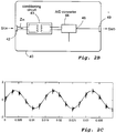
- the functions described in connection with the functional blocks in means 180 for digital signal processing, pre-processor 200 and evaluator 230 may be embodied by computer program code 94 and/or 104 as described in connection with memory blocks 90 and 100 in connection with Figure 4 above.
- Figure 12A is a flow chart illustrating an example of a method of performing step S70 so as to perform the peak level measurement session.
- the highest peak 430 in the measurement session illustrated in Figure 10 was generated in response to a disturbance, i.e. it reflects noise, and as such the peak 430 does not carry any information about the condition of the rotating part 8. Accordingly, it is desirable to obtain a representative peak amplitude value A PR which is based on signal values reflecting measurement values delivered by the sensor 10 in dependence on vibrations emanating from the shaft and/or bearing when the shaft rotates.
- n is a number having a numerical value of at least 2 and R has a numerical value of at least 8.
- Step S300 of the example method illustrated in Figure 12B may be performed after step S60, as described in connection with Figure 11B above.
- the peak level analyzer reads the current rotational speed f ROT , which may be delivered from the speed detector 450, as described above (See Fig. 5 ).
- the reading of a real time value of the rotational speed f ROT advantageously enables this method to be performed also when the rotational part to be analysed rotates with a variable speed of rotation.
- a step S320 the measurement signal S MDP , S R to be analyzed is received, and in a step S330 the amplitude of the received signal S R is analyzed so as to detect any received peak values.
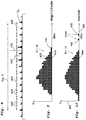
- the value sorter 370 may be adapted to deliver sorted amplitude values A P , e.g in the form of a table 470 or cumulative histogram table 530, as discussed and illustrated in connection with Figures 13B and/or 13C above.
- an operating bearing having like physical characteristics, and which may comprise a part of a machine, may be evaluated by measuring the relative velocity of its rolling elements and the peak amplitude values which occur within it. The lubricational condition of the operating bearing may then be evaluated with reference to the established schedule.
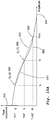
- FIG. 19 is an illustration of correlation between the amplitude of peaks A PL having an occurrence frequency of more than one peak per revolution and the elastohydrodynamic lubricant film parameter ⁇ .
- curve 720 represents reference signal peak values A PLref detected for the control bearing when it is a run in an unlubricated condition
- curve 726 represents signal peak values A PL detected for the control bearing when it is a run in a lubricated condition.
- the difference between the peak values A PLref obtained for the unlubricated control bearing and the signal peak values A PL detected for the lubricated control bearing at any given operating speed V r enables determination of the dampening effect upon shocks occurring within the bearing at that operating speed attributable to the addition of a sufficient elastohydrodynamic lubricant film.
- the elastohydrodynamic lubricant film parameter ⁇ for the lubricated control bearing may be readily determined by one of the methods hereinbefore described.
- said occurrence frequency value N L is a number in the range from 15 to 150.
Landscapes
- Physics & Mathematics (AREA)
- General Physics & Mathematics (AREA)
- Acoustics & Sound (AREA)
- Engineering & Computer Science (AREA)
- Chemical & Material Sciences (AREA)
- Health & Medical Sciences (AREA)
- Biochemistry (AREA)
- General Health & Medical Sciences (AREA)
- Life Sciences & Earth Sciences (AREA)
- Immunology (AREA)
- Pathology (AREA)
- Analytical Chemistry (AREA)
- Artificial Intelligence (AREA)
- Evolutionary Computation (AREA)
- Mathematical Physics (AREA)
- Automation & Control Theory (AREA)
- Testing Of Devices, Machine Parts, Or Other Structures Thereof (AREA)
- Measurement Of Mechanical Vibrations Or Ultrasonic Waves (AREA)
Claims (26)
- Procédé d'exploitation d'un appareil (14) pour analyser une condition de lubrification d'une pièce de machine en rotation avec une vitesse de rotation (fROT), comprenant les étapes consistant à :recevoir un premier signal (SMD, SR, SF) dépendant de vibrations mécaniques émanant d'une rotation de ladite pièce ;analyser ledit premier signal de façon à détecter des valeurs d'amplitude de crête (Ap) ;trier lesdites valeurs d'amplitude de crête détectées (Ap) en compartiments d'amplitude correspondants ;caractérisé parledit premier signal (SMD, SR, SF) étant un premier signal numérique (SMD, SR, SF) ; et parla mise en oeuvre de ladite analyse de détection de valeur d'amplitude de crête pendant une période de temps finie (TPmL), ladite période de temps finie correspondant à une certaine quantité (RS, RD) de révolution de ladite pièce en rotation ; ladite certaine quantité (RS, RD) de révolution correspondant à plus d'une révolution de ladite pièce en rotation ; dans lequellesdites valeurs d'amplitude de crête détectées (Ap) sont triées en compartiments d'amplitude correspondants de façon à refléter (470) une occurrence (N) de valeurs d'amplitude de crête détectées (Ap) au sein d'une pluralité de compartiments de plage d'amplitude ou de façon à refléter (530) l'occurrence (N') de crêtes détectées ayant une amplitude supérieure à l'amplitude (Ar') d'un compartiment d'amplitude associé (r) ; et parl'établissement d'une valeur d'amplitude de crête (APL) pour des valeurs d'amplitude de crête triées qui, pendant la période de temps finie (TPmL), ont eu une fréquence d'occurrence moyenne (NL) de plus d'une fois par révolution ; dans lequella valeur d'amplitude de crête établie (APL) est indicative de la condition de lubrification.
- Procédé selon la revendication 1, dans lequel
ladite étape d'établissement inclut :l'identification, lorsque ladite quantité prédéterminée (RS, RD) de révolution a été atteinte, d'un compartiment d'amplitude au sein duquel X valeurs d'amplitude ont été comptées, dans lequel
RD est un nombre correspondant à ladite quantité prédéterminée (RS, RD) de révolution ; etl'utilisation de la valeur d'amplitude de ladite plage d'amplitude identifiée en tant que ladite valeur d'amplitude de crête (APL). - Procédé selon la revendication 2, dans lequel
ladite plage d'amplitude est une plage (500, r) dans un histogramme de valeurs d'amplitude de crête détectées. - Procédé selon la revendication 1, dans lequel ladite étape d'établissement inclut :l'identification, lorsque ladite quantité prédéterminée (RS, RD) de révolution a été atteinte, d'un compartiment d'amplitude au sein duquel Z valeurs d'amplitude ont été comptées, dans lequel
Z reflète (530) une occurrence (N') de crêtes détectées ayant une amplitude supérieure à l'amplitude (Ar') du compartiment d'amplitude associé (r) ; et
RD est un nombre correspondant à ladite quantité prédéterminée de révolution ; et ladite étape d'établissement inclut en outrel'utilisation de la valeur d'amplitude de ladite plage d'amplitude identifiée en tant que ladite valeur d'amplitude de crête (APL). - Procédé selon une quelconque revendication précédente, dans lequelladite période de temps finie (TPm) est déterminée (875) en fonction d'une valeur prédéfinie de quantité (Rs) de révolution et d'un signal indicatif d'une quantité réelle (RD) de révolution ; dans lequelladite quantité prédéterminée (RS, RD) de révolution correspond à au moins une révolution de ladite pièce rotative surveillée ; ouladite quantité prédéterminée (RS, RD) de révolution correspond à au moins deux révolutions de ladite pièce rotative surveillée ; ouladite quantité prédéterminée (RS, RD) de révolution correspond à au moins trois révolutions de ladite pièce rotative surveillée ; ouladite quantité prédéterminée (RS, RD) de révolution correspond à au moins quatre révolutions de ladite pièce rotative surveillée ; ouladite quantité prédéterminée (RS, RD) de révolution correspond à au moins huit révolutions de ladite pièce rotative surveillée ; ouladite quantité prédéterminée (RS, RD) de révolution correspond à au moins dix révolutions de ladite pièce rotative surveillée.
- Procédé selon la revendication 1, dans lequel ladite étape d'établissement inclut :
la sélection de la Y:ème valeur de crête d'amplitude la plus élevée pour être ladite valeur d'amplitude de crête (APL) indicative d'une condition de lubrification ; dans lequel Rs est ladite quantité prédéterminée (Rs) de révolution ; etNL est un nombre entier ayant une valeur supérieure à un (1).
 - Procédé selon une quelconque revendication précédente, comprenant en outre
l'utilisation des valeurs d'amplitude (APL, APR) associées à au moins deux compartiments de plage d'amplitude parmi ladite pluralité de compartiments de plage d'amplitude en tant que valeurs indicatives de la condition de ladite pièce en rotation ; le procédé comprenant en outre
la distinction, sur la base du nombre d'occurrences (NL, NR) par révolution, desdites valeurs d'amplitude de crête détectées (Ap), entre des premières valeurs d'amplitude (APL) utilisées pour indiquer une condition de lubrification de surfaces de palier et
des deuxièmes valeurs d'amplitude (APR) utilisées pour indiquer un état mécanique de surfaces de palier. - Procédé selon la revendication 7, dans lequeldes valeurs d'amplitude (APL) utilisées pour indiquer une condition de lubrification de surfaces de palier ont une première valeur de fréquence d'occurrence (NL) en nombre de valeurs de crête par révolution ;ladite première valeur de fréquence d'occurrence (NL) étant un nombre supérieur à une valeur de crête par révolution.
- Procédé selon la revendication 7 ou 8, dans lequel
des valeurs d'amplitude (APR) utilisées pour indiquer un état mécanique de surfaces de palier ont une deuxième valeur de fréquence d'occurrence en nombre de valeurs de crête par révolution ;
ladite deuxième valeur de fréquence d'occurrence étant un nombre inférieur à une valeur de crête par révolution. - Procédé selon une quelconque revendication précédente, dans lequel
ladite valeur de fréquence d'occurrence NL est un nombre supérieur à dix. - Procédé selon une quelconque revendication précédente, dans lequel
ladite valeur de fréquence d'occurrence NL est un nombre dans la plage de 15 à 150. - Procédé selon une quelconque revendication précédente, dans lequel
ladite valeur de fréquence d'occurrence NL est un nombre dans la plage de 20 à 90. - Procédé selon une quelconque revendication précédente, dans lequel
ladite valeur de fréquence d'occurrence NL est un nombre dans la plage de 25 à 70. - Procédé selon une quelconque revendication précédente, dans lequel
ladite valeur de fréquence d'occurrence NL reflète un nombre de valeurs de crête par révolution d'une pièce surveillée. - Procédé selon une quelconque revendication précédente, dans lequel
la valeur d'amplitude de crête établie (APL) indicative d'une condition de lubrification est utilisée pour la surveillance de condition de pièces en rotation ayant une faible vitesse de rotation (fROT). - Procédé selon une quelconque revendication précédente, incluant :
l'analyse du signal numérique de façon à détecter des valeurs d'amplitude de crête (AP) pendant une période de temps finie (TPm), ladite période de temps finie correspondant à une quantité prédéterminée (RS, RD) de révolution de ladite pièce rotative ; ladite quantité prédéterminée (RS, RD) de révolution correspondant à au moins une révolution de ladite pièce rotative surveillée. - Procédé selon la revendication 16, dans lequel :
cette analyse fournit des résultats de mesure, qui sont comparables même lorsque la vitesse de rotation (fROT) varie. - Procédé selon la revendication 16 ou 17, dans lequel :
une première valeur (APL1) obtenue en mettant en oeuvre un procédé selon une quelconque revendication précédente à une première vitesse de rotation (fROT1) peut être comparée à une autre valeur (APL2) obtenue en mettant en oeuvre le même procédé selon une quelconque revendication précédente à une deuxième vitesse de rotation (fROT1). - Procédé selon une quelconque revendication précédente, dans lequel :lorsqu'une analyse simultanée est faite pour
établir une valeur d'amplitude de crête réelle (APR) qui est indicative de l'état mécanique de la pièce surveillée ; eten même temps
établir une valeur d'amplitude de crête (AP) qui est indicative de la condition de lubrification de la pièce surveillée,alors : la pièce en rotation est surveillée pendant une période de temps finie (TPM) correspondant à une certaine quantité (R) de révolution de ladite pièce rotative ; ladite certaine quantité (R) de révolution correspondant à au moins huit révolutions. - Procédé selon une quelconque revendication précédente, comprenant en outre :la conversion, par un transducteur (10), desdites vibrations mécaniques émanant d'une rotation de ladite pièce de machine, en un signal électrique analogique (SEA) ;l'échantillonnage, par un convertisseur analogique vers numérique (44) compris dans une interface de capteur (40), dudit signal électrique analogique (SEA) avec une certaine fréquence d'échantillonnage (fs) de façon à générer ledit premier signal numérique (SMD, SR, SF) de sorte que ledit premier signal numérique (SMD, SR, SF) ait ladite certaine fréquence d'échantillonnage (fs) et de sorte qu'une amplitude d'un échantillon de premier signal numérique dépende d'une amplitude du signal électrique analogique (SEA) au moment d'échantillonnage.
- Procédé selon la revendication 20, dans lequel :
ladite étape de conversion est faite par un transducteur comprenant un accéléromètre piézoélectrique résonant (10). - Procédé selon la revendication 20, dans lequel :
ladite étape de conversion est faite par un capteur de mesure d'impulsion de choc résonant (10). - Appareil (14) pour analyser une condition de lubrification d'une pièce de machine en rotation avec une vitesse de rotation (fROT), comprenant :un détecteur de crête (310) ayant une entrée (220) pour recevoir un premier signal (SMD, SR, SF) dépendant de vibrations mécaniques émanant d'une rotation de ladite pièce de machine en rotation ;ledit détecteur de crête (310) étant conçu pour analyser ledit premier signal de façon à détecter des valeurs d'amplitude de crête (Ap) ;une trieuse de valeurs (870) conçue pour trier lesdites valeurs d'amplitude de crête détectées (Ap) en plages d'amplitude correspondantes ;caractérisé en ce queledit premier signal est un premier signal numérique (SMD, SR, SF) et en ce queledit appareil (14) est conçu pour analyser ledit premier signal numérique (SMD, SR, SF) pendant une période de temps finie (TPmL), ladite période de temps finie correspondant à une quantité prédéterminée (RS, RD) de révolution de ladite pièce de machine en rotation ; ladite quantité prédéterminée (RS, RD) de révolution correspondant à plus d'une révolution de ladite pièce de machine en rotation ; et en ce queladite trieuse de valeurs (870) est conçue pour trier lesdites valeurs d'amplitude de crête détectées (Ap) en plages d'amplitude correspondantes (Ari) de façon à refléter (470) une occurrence (Nri) de valeurs d'amplitude de crête détectées (Ap) au sein d'une pluralité de plages d'amplitude (Ari) ou de façon à refléter (530) une occurrence (Nri') de valeurs d'amplitude de crête détectées (Ap) ayant une amplitude supérieure à l'amplitude (Ari') d'une plage d'amplitude associée (ri) ; et en ce queun dispositif d'établissement de valeur de crête de lubrification (875) est conçu pour établir une valeur d'amplitude de crête (APL) qui, pendant la période de temps finie (TPmL), a eu une fréquence d'occurrence moyenne (NL) de plus d'une fois par révolution ; dans lequel la valeur d'amplitude de crête établie (APL) est indicative de la condition de lubrification.
- Système pour indiquer la condition de lubrification d'un palier opérationnel comprenant :
l'appareil selon la revendication 23, dans lequel ladite pièce de machine en rotation est ledit palier opérationnel, le système comprenant en outre :un moyen pour relier ladite valeur d'amplitude de crête établie (APL) à des informations de référence contenues au sein d'une mémoire (879, 60, 52) etun moyen (878) pour fournir une sortie (APLNorm) indicative d'une épaisseur de film de lubrifiant du lubrifiant dans ledit palier opérationnel en fonction de ladite relation. - Système selon la revendication 24, dans lequel
ledit moyen pour relier est conçu pour créer une sortie visuelle indicative de ladite valeur d'amplitude de crête établie (APL) et indicative desdites informations de référence contenues au sein d'une mémoire (879, 60, 52). - Système selon la revendication 24, dans lequel
ledit moyen pour relier est conçu pour calculer une valeur (APLNorm) en fonction de ladite valeur d'amplitude de crête établie (APL) et desdites informations de référence.
Priority Applications (1)
| Application Number | Priority Date | Filing Date | Title |
|---|---|---|---|
| EP19162332.1A EP3527961A1 (fr) | 2011-07-14 | 2012-07-11 | Système de surveillance d'état |
Applications Claiming Priority (2)
| Application Number | Priority Date | Filing Date | Title |
|---|---|---|---|
| SE1150683 | 2011-07-14 | ||
| PCT/SE2012/050827 WO2013009258A1 (fr) | 2011-07-14 | 2012-07-11 | Procédé et système d'analyse de l'état d'une pièce rotative d'une machine |
Related Child Applications (1)
| Application Number | Title | Priority Date | Filing Date |
|---|---|---|---|
| EP19162332.1A Division EP3527961A1 (fr) | 2011-07-14 | 2012-07-11 | Système de surveillance d'état |
Publications (3)
| Publication Number | Publication Date |
|---|---|
| EP2732251A1 EP2732251A1 (fr) | 2014-05-21 |
| EP2732251A4 EP2732251A4 (fr) | 2015-10-14 |
| EP2732251B1 true EP2732251B1 (fr) | 2019-03-13 |
Family
ID=47506315
Family Applications (2)
| Application Number | Title | Priority Date | Filing Date |
|---|---|---|---|
| EP12810816.4A Active EP2732251B1 (fr) | 2011-07-14 | 2012-07-11 | Procédé et système d'analyse de l'état d'une pièce rotative d'une machine |
| EP19162332.1A Withdrawn EP3527961A1 (fr) | 2011-07-14 | 2012-07-11 | Système de surveillance d'état |
Family Applications After (1)
| Application Number | Title | Priority Date | Filing Date |
|---|---|---|---|
| EP19162332.1A Withdrawn EP3527961A1 (fr) | 2011-07-14 | 2012-07-11 | Système de surveillance d'état |
Country Status (6)
| Country | Link |
|---|---|
| US (2) | US10203242B2 (fr) |
| EP (2) | EP2732251B1 (fr) |
| CN (1) | CN103688144B (fr) |
| EA (1) | EA027452B1 (fr) |
| TW (1) | TW201319527A (fr) |
| WO (1) | WO2013009258A1 (fr) |
Families Citing this family (43)
| Publication number | Priority date | Publication date | Assignee | Title |
|---|---|---|---|---|
| EA021908B1 (ru) | 2008-12-22 | 2015-09-30 | С.П.М. Инструмент Аб | Способ, устройство и машиночитаемый носитель для анализа состояния машины, имеющей вращающуюся часть |
| TWI509536B (zh) * | 2014-01-03 | 2015-11-21 | Univ Nat Formosa | Diagnostic Method of Gearbox Assembly Error |
| US9846919B2 (en) * | 2015-02-16 | 2017-12-19 | Samsung Electronics Co., Ltd. | Data processing device for processing multiple sensor data and system including the same |
| US20170051682A1 (en) * | 2015-08-20 | 2017-02-23 | General Electric Company | System and method for abatement of dynamic property changes with proactive diagnostics and conditioning |
| JP6659384B2 (ja) | 2016-02-02 | 2020-03-04 | 株式会社神戸製鋼所 | 回転機の異常検知装置および回転機の異常検知システム |
| US10401823B2 (en) * | 2016-02-04 | 2019-09-03 | Makino Inc. | Real time machining process monitoring utilizing preprocess simulation |
| JP6573838B2 (ja) * | 2016-02-10 | 2019-09-11 | 株式会社神戸製鋼所 | 回転機の異常検知システム |
| IT201600099499A1 (it) * | 2016-10-04 | 2018-04-04 | Carel Ind Spa | Dispositivo per il rilevamento di una condizione di lubrificazione ottimizzabile in un compressore di un impianto frigorifero, gruppo compressore che lo comprende e metodo per il rilevamento di una condizione di lubrificazione ottimizzabile in un compressore di un impianto frigorifero |
| DE102016013406B4 (de) | 2016-11-11 | 2022-02-03 | Schenck Process Europe Gmbh | Verfahren zum Betrieb eines Zustandsüberwachungssystems einer Schwingmaschine und Zustandsüberwachungssystem |
| EP3605037B1 (fr) * | 2017-03-24 | 2023-07-12 | NSK Ltd. | Système de diagnostique d'élément de machine |
| DE102017107814B4 (de) * | 2017-04-11 | 2022-01-05 | Phoenix Contact Gmbh & Co. Kg | Zustandsüberwachungsgerät zum Überwachen des Zustands einer mechanischen Maschinenkomponente |
| CN110537082B (zh) * | 2017-04-21 | 2022-06-03 | 三菱电机工程技术株式会社 | 振动检测装置及异常判定系统 |
| DE102017109460A1 (de) * | 2017-05-03 | 2018-11-08 | Prüftechnik Dieter Busch AG | System und Verfahren zur Schwingungsmessung an einer Maschine |
| US10655607B2 (en) * | 2017-06-02 | 2020-05-19 | General Electric Company | Systems and methods for detecting damage in wind turbine bearings |
| US11059141B2 (en) * | 2017-08-22 | 2021-07-13 | Gemini Precision Machining, Inc. | Smart tool system |
| JP6538782B2 (ja) * | 2017-08-28 | 2019-07-03 | ファナック株式会社 | モータ故障診断システム |
| CN109813544B (zh) * | 2019-03-26 | 2019-11-05 | 武汉众犇慧通科技有限公司 | 一种基于在线监测的旋转机械早期故障诊断方法及系统 |
| EP3977086A1 (fr) * | 2019-05-31 | 2022-04-06 | Abb Schweiz Ag | Procédé et dispositif de surveillance d'état permettant la surveillance d'un équipement rotatif |
| DE102020120744A1 (de) * | 2019-09-10 | 2021-03-11 | Omron Corporation | Diagnosegerät, -verfahren und -programm |
| JP7371512B2 (ja) * | 2019-09-10 | 2023-10-31 | オムロン株式会社 | 診断装置、方法、及びプログラム |
| US10931115B1 (en) | 2019-09-30 | 2021-02-23 | General Electric Company | Electrical power systems having a cluster transformer with multiple primary windings |
| KR102316496B1 (ko) * | 2019-10-15 | 2021-10-22 | (주)아이티공간 | 분포도를 통한 기기의 예지 보전방법 |
| US11041404B2 (en) | 2019-11-04 | 2021-06-22 | Raytheon Technologies Corporation | In-situ wireless monitoring of engine bearings |
| CN110823575B (zh) * | 2019-11-09 | 2021-03-16 | 北京工业大学 | 一种基于性能退化字典构造与相似性的轴承寿命预测方法 |
| CN110823580B (zh) * | 2019-11-12 | 2021-03-30 | 中国航发南方工业有限公司 | 航空发动机高温涡轮机匣部位的振动测试方法 |
| IT201900024030A1 (it) * | 2019-12-16 | 2021-06-16 | Skf Ab | A system and method for determining bearing preload by vibration measurement |
| KR102292393B1 (ko) * | 2020-02-17 | 2021-08-23 | 엘지전자 주식회사 | 압축기 및 칠러 시스템 |
| JP7379241B2 (ja) * | 2020-03-25 | 2023-11-14 | 三菱重工業株式会社 | 回転機の診断監視装置及び方法 |
| DE102020204228A1 (de) * | 2020-04-01 | 2021-10-07 | Aktiebolaget Skf | Vorrichtung zum Identifizieren eines Typs eines Lagers |
| AU2021252831A1 (en) | 2020-04-09 | 2022-10-27 | S.P.M. Instrument Ab | System for controlling an internal state of a tumbling mill |
| CN111677853B (zh) * | 2020-05-09 | 2021-11-19 | 联合轲麟新能源科技(济宁)有限公司 | 用于车辆低转速区的变速箱控制系统、汽车和控制方法 |
| CN111458149B (zh) * | 2020-06-01 | 2022-03-01 | 合肥工业大学 | 一种滚动轴承性能及使用寿命的预测方法及系统 |
| CN111855211B (zh) * | 2020-07-31 | 2021-05-07 | 北京航空航天大学 | 一种用于故障特征增强的最优解调频带确定方法 |
| JP7589505B2 (ja) * | 2020-10-29 | 2024-11-26 | 株式会社リコー | 診断装置、診断方法、プログラム、および加工システム |
| EP4264206B1 (fr) | 2020-12-21 | 2024-11-20 | TDK Corporation | Procédé et système de détermination de vibrations générées par un dispositif |
| WO2022135699A1 (fr) * | 2020-12-22 | 2022-06-30 | Abb Schweiz Ag | Procédé de détection de dégradation de lubrifiant dans une machine électrique |
| US12535384B2 (en) * | 2021-01-26 | 2026-01-27 | University Of South Carolina | Acoustic emission damage classification of rotating machinery via intensity analysis |
| CN113503961B (zh) * | 2021-07-22 | 2023-10-24 | 苏州苏试试验集团股份有限公司 | 一种冲击振动传感器信号的拾取方法 |
| CA3232805A1 (fr) | 2021-10-09 | 2023-04-13 | Tim Sundstrom | Systeme et procede de commande de pompe sur la base de vibrations de pompe |
| TWI819824B (zh) * | 2022-09-30 | 2023-10-21 | 中國鋼鐵股份有限公司 | 應用不同轉速振動閥值之設備異常監診方法 |
| EP4357749B1 (fr) * | 2022-10-19 | 2025-02-26 | IMS Gear SE & Co. KGaA | Procédé de détection automatique d'usure, de dommages de denture et/ou de dommages de palier sur une boîte de vitesses |
| CN116484169A (zh) * | 2023-04-06 | 2023-07-25 | 重庆大学 | 一种gis/gil设备机械缺陷诊断方法、评估方法及系统 |
| CN120105206B (zh) * | 2025-05-06 | 2025-07-11 | 汉江国家实验室 | 一种载流管路窄带谱振动诱发载荷类型辨识方法及系统 |
Family Cites Families (61)
| Publication number | Priority date | Publication date | Assignee | Title |
|---|---|---|---|---|
| US3554012A (en) | 1968-02-29 | 1971-01-12 | Iko Konsultbyron Ab | Method and arrangement for determining the mechanical state of machines |
| US3705516A (en) * | 1971-09-30 | 1972-12-12 | Northrop Corp | Method and apparatus for testing the condition of a machine |
| US4528852A (en) | 1982-10-21 | 1985-07-16 | Spm Instruments U.S. Inc. | Method and instrument for determining the condition of an operating bearing |
| JPS60195426A (ja) | 1984-03-16 | 1985-10-03 | Komatsu Ltd | 回転機構の故障診断方法 |
| DE3424692A1 (de) | 1984-07-05 | 1986-02-06 | Kletek Controllsysteme GmbH & Co KG, 2820 Bremen | Verfahren und messanordnung zur analyse von periodischen oder quasi periodischen signalen, insbesondere von schallsignalen bei maschinen und anlagen |
| GB2190198A (en) | 1986-04-28 | 1987-11-11 | Vipac Pty Ltd | Vibrational analysis system for a machine |
| US5258923A (en) | 1987-07-22 | 1993-11-02 | General Electric Company | System and method for detecting the occurrence, location and depth of cracks in turbine-generator rotors |
| JPH01127934A (ja) | 1987-11-12 | 1989-05-19 | Hitachi Ltd | 損傷診断装置 |
| US4912661A (en) | 1987-12-01 | 1990-03-27 | Hewlett-Packard Company | Tracking and resampling method and apparatus for monitoring the performance of rotating machines |
| JPH01178814A (ja) | 1988-01-08 | 1989-07-17 | Mitsubishi Heavy Ind Ltd | 信号の大局的構造認識装置 |
| GB2228088B (en) | 1988-12-16 | 1992-09-16 | Nippon Seiko Kk | Method and apparatus for detecting cracks in bearings |
| JPH02298825A (ja) * | 1989-05-13 | 1990-12-11 | Nippondenso Co Ltd | 回転機のための異常検査装置 |
| US5109700A (en) | 1990-07-13 | 1992-05-05 | Life Systems, Inc. | Method and apparatus for analyzing rotating machines |
| JPH04279826A (ja) | 1991-03-08 | 1992-10-05 | Nkk Corp | 可変速回転系異常診断方法及びその装置 |
| US5201292A (en) | 1991-08-30 | 1993-04-13 | Loral Aerospace Corp. | Apparatus and method for detecting vibration patterns |
| US5501105A (en) | 1991-10-02 | 1996-03-26 | Monitoring Technology Corp. | Digital signal processing of encoder signals to detect resonances in rotating machines |
| US5365787A (en) | 1991-10-02 | 1994-11-22 | Monitoring Technology Corp. | Noninvasive method and apparatus for determining resonance information for rotating machinery components and for anticipating component failure from changes therein |
| US5445028A (en) | 1992-09-18 | 1995-08-29 | Ametek Aerospace Products Inc. | Dynamic digital tracking filter |
| US5390545A (en) * | 1993-01-11 | 1995-02-21 | Caterpillar Inc. | Apparatus for measuring torsional vibrations of rotating machinery |
| CA2152497C (fr) | 1993-11-09 | 1999-01-12 | Lawrence Edwin Connell | Procede et dispositif d'entree servant a detecter le niveau d'un signal d'entree |
| US5633811A (en) | 1994-12-09 | 1997-05-27 | Computational Systems, Inc. | Hand held data collector and analyzer system |
| US5895857A (en) | 1995-11-08 | 1999-04-20 | Csi Technology, Inc. | Machine fault detection using vibration signal peak detector |
| SE510771C2 (sv) | 1996-07-05 | 1999-06-21 | Spm Instr Ab | Förfarande för utvärdering av konditionen för en maskin jämte analysapparat samt anordning för samverkan med analysapparaten |
| US5852793A (en) | 1997-02-18 | 1998-12-22 | Dme Corporation | Method and apparatus for predictive diagnosis of moving machine parts |
| JP3425331B2 (ja) | 1997-06-30 | 2003-07-14 | 株式会社東芝 | 電源装置 |
| US6351714B1 (en) | 1998-03-03 | 2002-02-26 | Entek Ird International Corporation | Order tracking signal sampling process |
| FI112972B (fi) | 1998-07-15 | 2004-02-13 | Abb Research Ltd | Laakerin kunnon arviointi |
| US6053047A (en) | 1998-09-29 | 2000-04-25 | Allen-Bradley Company, Llc | Determining faults in multiple bearings using one vibration sensor |
| AUPQ152499A0 (en) | 1999-07-09 | 1999-08-05 | Commonwealth Scientific And Industrial Research Organisation | A system for monitoring acoustic emissions from a moving machine |
| US6868348B1 (en) | 1999-10-29 | 2005-03-15 | Entek Ird International Corporation | Adaptive high frequency energy detection |
| US6351713B1 (en) * | 1999-12-15 | 2002-02-26 | Swantech, L.L.C. | Distributed stress wave analysis system |
| US6332116B1 (en) | 2000-04-19 | 2001-12-18 | National Instruments Corporation | System and method for analyzing signals of rotating machines |
| US6591682B1 (en) | 2000-08-14 | 2003-07-15 | Pruftechnik Dieter Busch Ag | Device and process for signal analysis |
| US6801864B2 (en) | 2001-03-13 | 2004-10-05 | Ab Skf | System and method for analyzing vibration signals |
| US7136794B1 (en) * | 2001-05-24 | 2006-11-14 | Simmonds Precision Products, Inc. | Method and apparatus for estimating values for condition indicators |
| TW579424B (en) * | 2001-07-09 | 2004-03-11 | Shell Int Research | Vibration analysis for predictive maintenance in machinery |
| US20030040885A1 (en) * | 2001-08-14 | 2003-02-27 | Schoess Jeffrey N. | Apparatus and method for determining vehicle load weight status |
| ATE485497T1 (de) | 2001-12-04 | 2010-11-15 | Skf Condition Monitoring Inc | Zyklische zeitmittelung zur maschinenüberwachung |
| EP1474664B1 (fr) | 2002-01-18 | 2006-03-29 | SPM Instrument AB | Appareil d'analyse des conditions d'une machine |
| US6618128B2 (en) | 2002-01-23 | 2003-09-09 | Csi Technology, Inc. | Optical speed sensing system |
| US6668234B2 (en) | 2002-03-22 | 2003-12-23 | Abb Inc. | Method and apparatus for calculating the amplitude of a complex waveform associated with a rotating machine shaft after removing the running speed frequency |
| JP3880455B2 (ja) | 2002-05-31 | 2007-02-14 | 中国電力株式会社 | 転がり軸受の余寿命診断方法及びこの余寿命診断装置 |
| US7133801B2 (en) | 2002-06-07 | 2006-11-07 | Exxon Mobil Research And Engineering Company | System and methodology for vibration analysis and condition monitoring |
| US7243064B2 (en) | 2002-11-14 | 2007-07-10 | Verizon Business Global Llc | Signal processing of multi-channel data |
| EP1513254A1 (fr) | 2003-08-26 | 2005-03-09 | Mitsubishi Electric Information Technology Centre Europe B.V. | Filtre permettant la décimation de signaux numériques par un facteur rationnel |
| JP2006113002A (ja) | 2004-10-18 | 2006-04-27 | Nsk Ltd | 機械設備の異常診断システム |
| WO2006043511A1 (fr) | 2004-10-18 | 2006-04-27 | Nsk Ltd. | Systeme de diagnostic d’anomalie pour une machinerie |
| NZ537244A (en) | 2004-12-16 | 2006-10-27 | Commtest Instr Ltd | Improvements in or relating to vibration analysis |
| WO2007137132A2 (fr) * | 2006-05-17 | 2007-11-29 | Curtiss-Wright Flow Control Corporation | Système d'analyse probabiliste des ondes de contrainte, et procédé associé |
| FR2913769B1 (fr) * | 2007-03-12 | 2009-06-05 | Snecma Sa | Procede de detection d'un endommagement d'un roulement de palier d'un moteur |
| GB0714379D0 (en) * | 2007-07-21 | 2007-09-05 | Monition Ltd | Tamping bank monitoring apparatus and method |
| US7761256B2 (en) | 2007-12-21 | 2010-07-20 | General Electric Company | Method and system for use in analyzing vibrations of a variable speed rotating body |
| DK2085902T3 (en) | 2008-02-02 | 2018-03-12 | Siemens Ind Software Nv | Order tracking method and system |
| WO2010007645A1 (fr) | 2008-07-15 | 2010-01-21 | グローリー株式会社 | Dispositif de distribution de ticket, dispositif de traitement de ticket et système de ticket |
| US9109748B2 (en) * | 2008-12-16 | 2015-08-18 | Rockwell Automation Technologies, Inc. | Machine conditioning monitoring closed loop lubrication system and method |
| EP2373971B1 (fr) | 2008-12-22 | 2022-01-26 | S.P.M. Instrument AB | Système d'analyse |
| EA021908B1 (ru) | 2008-12-22 | 2015-09-30 | С.П.М. Инструмент Аб | Способ, устройство и машиночитаемый носитель для анализа состояния машины, имеющей вращающуюся часть |
| US8812265B2 (en) | 2008-12-22 | 2014-08-19 | S.P.M. Instrument Ab | Analysis system |
| US20100292937A1 (en) * | 2009-05-18 | 2010-11-18 | Diaa Hosny | Turbocharger bearing health monitor |
| SE535559C2 (sv) | 2010-01-18 | 2012-09-25 | Spm Instr Ab | Förfarande och anordning för analys av tillståndet hos maskin med roterande del |
| DE102010002294A1 (de) * | 2010-02-24 | 2011-08-25 | Siemens Aktiengesellschaft, 80333 | System bzw. Verfahren zur Ermittlung eines Lagerzustandes |
-
2012
- 2012-07-11 EP EP12810816.4A patent/EP2732251B1/fr active Active
- 2012-07-11 EP EP19162332.1A patent/EP3527961A1/fr not_active Withdrawn
- 2012-07-11 US US14/131,731 patent/US10203242B2/en active Active
- 2012-07-11 WO PCT/SE2012/050827 patent/WO2013009258A1/fr not_active Ceased
- 2012-07-11 EA EA201490284A patent/EA027452B1/ru not_active IP Right Cessation
- 2012-07-11 CN CN201280034754.8A patent/CN103688144B/zh active Active
- 2012-07-12 TW TW101125073A patent/TW201319527A/zh unknown
-
2018
- 2018-12-19 US US16/226,065 patent/US11054301B2/en active Active
Non-Patent Citations (1)
| Title |
|---|
| None * |
Also Published As
| Publication number | Publication date |
|---|---|
| EA201490284A1 (ru) | 2014-06-30 |
| EA027452B1 (ru) | 2017-07-31 |
| EP2732251A1 (fr) | 2014-05-21 |
| US10203242B2 (en) | 2019-02-12 |
| TW201319527A (zh) | 2013-05-16 |
| WO2013009258A1 (fr) | 2013-01-17 |
| EP3527961A1 (fr) | 2019-08-21 |
| EP2732251A4 (fr) | 2015-10-14 |
| US20140142872A1 (en) | 2014-05-22 |
| US20190271584A1 (en) | 2019-09-05 |
| US11054301B2 (en) | 2021-07-06 |
| CN103688144B (zh) | 2017-04-12 |
| CN103688144A (zh) | 2014-03-26 |
Similar Documents
| Publication | Publication Date | Title |
|---|---|---|
| US11054301B2 (en) | Method and a system for analysing the condition of a rotating machine part | |
| US20230304849A1 (en) | Apparatus for analysing the condition of a machine having a rotating part | |
| US11614357B2 (en) | Apparatus for monitoring the condition of a machine | |
| US11599085B2 (en) | Method and apparatus for analysing the condition of a machine having a rotating part | |
| US20210223094A1 (en) | Apparatus and a method for analysing the vibration of a machine having a rotating part | |
| US10809152B2 (en) | Analysis system | |
| CA2668279C (fr) | Dispositif et procede de surveillance de l'etat vibratoire d'une machine tournante | |
| US20160334269A1 (en) | Analysis system | |
| Lu et al. | Instrument for bearing fault diagnosis based on demodulated resonance technology |
Legal Events
| Date | Code | Title | Description |
|---|---|---|---|
| PUAI | Public reference made under article 153(3) epc to a published international application that has entered the european phase |
Free format text: ORIGINAL CODE: 0009012 |
|
| 17P | Request for examination filed |
Effective date: 20140114 |
|
| AK | Designated contracting states |
Kind code of ref document: A1 Designated state(s): AL AT BE BG CH CY CZ DE DK EE ES FI FR GB GR HR HU IE IS IT LI LT LU LV MC MK MT NL NO PL PT RO RS SE SI SK SM TR |
|
| DAX | Request for extension of the european patent (deleted) | ||
| RA4 | Supplementary search report drawn up and despatched (corrected) |
Effective date: 20150916 |
|
| RIC1 | Information provided on ipc code assigned before grant |
Ipc: G01H 1/00 20060101AFI20150910BHEP Ipc: F16C 1/24 20060101ALI20150910BHEP Ipc: F16N 29/00 20060101ALI20150910BHEP Ipc: G01N 29/14 20060101ALI20150910BHEP Ipc: G01M 13/04 20060101ALI20150910BHEP |
|
| 17Q | First examination report despatched |
Effective date: 20160620 |
|
| STAA | Information on the status of an ep patent application or granted ep patent |
Free format text: STATUS: EXAMINATION IS IN PROGRESS |
|
| GRAP | Despatch of communication of intention to grant a patent |
Free format text: ORIGINAL CODE: EPIDOSNIGR1 |
|
| STAA | Information on the status of an ep patent application or granted ep patent |
Free format text: STATUS: GRANT OF PATENT IS INTENDED |
|
| INTG | Intention to grant announced |
Effective date: 20180917 |
|
| GRAS | Grant fee paid |
Free format text: ORIGINAL CODE: EPIDOSNIGR3 |
|
| GRAA | (expected) grant |
Free format text: ORIGINAL CODE: 0009210 |
|
| STAA | Information on the status of an ep patent application or granted ep patent |
Free format text: STATUS: THE PATENT HAS BEEN GRANTED |
|
| AK | Designated contracting states |
Kind code of ref document: B1 Designated state(s): AL AT BE BG CH CY CZ DE DK EE ES FI FR GB GR HR HU IE IS IT LI LT LU LV MC MK MT NL NO PL PT RO RS SE SI SK SM TR |
|
| RAP1 | Party data changed (applicant data changed or rights of an application transferred) |
Owner name: S.P.M. INSTRUMENT AB |
|
| REG | Reference to a national code |
Ref country code: GB Ref legal event code: FG4D |
|
| REG | Reference to a national code |
Ref country code: CH Ref legal event code: EP Ref country code: AT Ref legal event code: REF Ref document number: 1108351 Country of ref document: AT Kind code of ref document: T Effective date: 20190315 |
|
| REG | Reference to a national code |
Ref country code: IE Ref legal event code: FG4D |
|
| REG | Reference to a national code |
Ref country code: DE Ref legal event code: R096 Ref document number: 602012057837 Country of ref document: DE |
|
| REG | Reference to a national code |
Ref country code: NL Ref legal event code: FP |
|
| REG | Reference to a national code |
Ref country code: SE Ref legal event code: TRGR |
|
| REG | Reference to a national code |
Ref country code: LT Ref legal event code: MG4D |
|
| PG25 | Lapsed in a contracting state [announced via postgrant information from national office to epo] |
Ref country code: NO Free format text: LAPSE BECAUSE OF FAILURE TO SUBMIT A TRANSLATION OF THE DESCRIPTION OR TO PAY THE FEE WITHIN THE PRESCRIBED TIME-LIMIT Effective date: 20190613 Ref country code: FI Free format text: LAPSE BECAUSE OF FAILURE TO SUBMIT A TRANSLATION OF THE DESCRIPTION OR TO PAY THE FEE WITHIN THE PRESCRIBED TIME-LIMIT Effective date: 20190313 Ref country code: LT Free format text: LAPSE BECAUSE OF FAILURE TO SUBMIT A TRANSLATION OF THE DESCRIPTION OR TO PAY THE FEE WITHIN THE PRESCRIBED TIME-LIMIT Effective date: 20190313 |
|
| PG25 | Lapsed in a contracting state [announced via postgrant information from national office to epo] |
Ref country code: RS Free format text: LAPSE BECAUSE OF FAILURE TO SUBMIT A TRANSLATION OF THE DESCRIPTION OR TO PAY THE FEE WITHIN THE PRESCRIBED TIME-LIMIT Effective date: 20190313 Ref country code: HR Free format text: LAPSE BECAUSE OF FAILURE TO SUBMIT A TRANSLATION OF THE DESCRIPTION OR TO PAY THE FEE WITHIN THE PRESCRIBED TIME-LIMIT Effective date: 20190313 Ref country code: GR Free format text: LAPSE BECAUSE OF FAILURE TO SUBMIT A TRANSLATION OF THE DESCRIPTION OR TO PAY THE FEE WITHIN THE PRESCRIBED TIME-LIMIT Effective date: 20190614 Ref country code: BG Free format text: LAPSE BECAUSE OF FAILURE TO SUBMIT A TRANSLATION OF THE DESCRIPTION OR TO PAY THE FEE WITHIN THE PRESCRIBED TIME-LIMIT Effective date: 20190613 Ref country code: LV Free format text: LAPSE BECAUSE OF FAILURE TO SUBMIT A TRANSLATION OF THE DESCRIPTION OR TO PAY THE FEE WITHIN THE PRESCRIBED TIME-LIMIT Effective date: 20190313 |
|
| REG | Reference to a national code |
Ref country code: AT Ref legal event code: MK05 Ref document number: 1108351 Country of ref document: AT Kind code of ref document: T Effective date: 20190313 |
|
| PG25 | Lapsed in a contracting state [announced via postgrant information from national office to epo] |
Ref country code: EE Free format text: LAPSE BECAUSE OF FAILURE TO SUBMIT A TRANSLATION OF THE DESCRIPTION OR TO PAY THE FEE WITHIN THE PRESCRIBED TIME-LIMIT Effective date: 20190313 Ref country code: IT Free format text: LAPSE BECAUSE OF FAILURE TO SUBMIT A TRANSLATION OF THE DESCRIPTION OR TO PAY THE FEE WITHIN THE PRESCRIBED TIME-LIMIT Effective date: 20190313 Ref country code: CZ Free format text: LAPSE BECAUSE OF FAILURE TO SUBMIT A TRANSLATION OF THE DESCRIPTION OR TO PAY THE FEE WITHIN THE PRESCRIBED TIME-LIMIT Effective date: 20190313 Ref country code: PT Free format text: LAPSE BECAUSE OF FAILURE TO SUBMIT A TRANSLATION OF THE DESCRIPTION OR TO PAY THE FEE WITHIN THE PRESCRIBED TIME-LIMIT Effective date: 20190713 Ref country code: AL Free format text: LAPSE BECAUSE OF FAILURE TO SUBMIT A TRANSLATION OF THE DESCRIPTION OR TO PAY THE FEE WITHIN THE PRESCRIBED TIME-LIMIT Effective date: 20190313 Ref country code: RO Free format text: LAPSE BECAUSE OF FAILURE TO SUBMIT A TRANSLATION OF THE DESCRIPTION OR TO PAY THE FEE WITHIN THE PRESCRIBED TIME-LIMIT Effective date: 20190313 Ref country code: SK Free format text: LAPSE BECAUSE OF FAILURE TO SUBMIT A TRANSLATION OF THE DESCRIPTION OR TO PAY THE FEE WITHIN THE PRESCRIBED TIME-LIMIT Effective date: 20190313 Ref country code: ES Free format text: LAPSE BECAUSE OF FAILURE TO SUBMIT A TRANSLATION OF THE DESCRIPTION OR TO PAY THE FEE WITHIN THE PRESCRIBED TIME-LIMIT Effective date: 20190313 |
|
| PG25 | Lapsed in a contracting state [announced via postgrant information from national office to epo] |
Ref country code: PL Free format text: LAPSE BECAUSE OF FAILURE TO SUBMIT A TRANSLATION OF THE DESCRIPTION OR TO PAY THE FEE WITHIN THE PRESCRIBED TIME-LIMIT Effective date: 20190313 Ref country code: SM Free format text: LAPSE BECAUSE OF FAILURE TO SUBMIT A TRANSLATION OF THE DESCRIPTION OR TO PAY THE FEE WITHIN THE PRESCRIBED TIME-LIMIT Effective date: 20190313 |
|
| REG | Reference to a national code |
Ref country code: DE Ref legal event code: R097 Ref document number: 602012057837 Country of ref document: DE |
|
| PG25 | Lapsed in a contracting state [announced via postgrant information from national office to epo] |
Ref country code: AT Free format text: LAPSE BECAUSE OF FAILURE TO SUBMIT A TRANSLATION OF THE DESCRIPTION OR TO PAY THE FEE WITHIN THE PRESCRIBED TIME-LIMIT Effective date: 20190313 Ref country code: IS Free format text: LAPSE BECAUSE OF FAILURE TO SUBMIT A TRANSLATION OF THE DESCRIPTION OR TO PAY THE FEE WITHIN THE PRESCRIBED TIME-LIMIT Effective date: 20190713 |
|
| PLBE | No opposition filed within time limit |
Free format text: ORIGINAL CODE: 0009261 |
|
| STAA | Information on the status of an ep patent application or granted ep patent |
Free format text: STATUS: NO OPPOSITION FILED WITHIN TIME LIMIT |
|
| PG25 | Lapsed in a contracting state [announced via postgrant information from national office to epo] |
Ref country code: DK Free format text: LAPSE BECAUSE OF FAILURE TO SUBMIT A TRANSLATION OF THE DESCRIPTION OR TO PAY THE FEE WITHIN THE PRESCRIBED TIME-LIMIT Effective date: 20190313 |
|
| 26N | No opposition filed |
Effective date: 20191216 |
|
| PG25 | Lapsed in a contracting state [announced via postgrant information from national office to epo] |
Ref country code: SI Free format text: LAPSE BECAUSE OF FAILURE TO SUBMIT A TRANSLATION OF THE DESCRIPTION OR TO PAY THE FEE WITHIN THE PRESCRIBED TIME-LIMIT Effective date: 20190313 Ref country code: MC Free format text: LAPSE BECAUSE OF FAILURE TO SUBMIT A TRANSLATION OF THE DESCRIPTION OR TO PAY THE FEE WITHIN THE PRESCRIBED TIME-LIMIT Effective date: 20190313 |
|
| REG | Reference to a national code |
Ref country code: CH Ref legal event code: PL |
|
| PG25 | Lapsed in a contracting state [announced via postgrant information from national office to epo] |
Ref country code: TR Free format text: LAPSE BECAUSE OF FAILURE TO SUBMIT A TRANSLATION OF THE DESCRIPTION OR TO PAY THE FEE WITHIN THE PRESCRIBED TIME-LIMIT Effective date: 20190313 |
|
| REG | Reference to a national code |
Ref country code: BE Ref legal event code: MM Effective date: 20190731 |
|
| PG25 | Lapsed in a contracting state [announced via postgrant information from national office to epo] |
Ref country code: LI Free format text: LAPSE BECAUSE OF NON-PAYMENT OF DUE FEES Effective date: 20190731 Ref country code: LU Free format text: LAPSE BECAUSE OF NON-PAYMENT OF DUE FEES Effective date: 20190711 Ref country code: BE Free format text: LAPSE BECAUSE OF NON-PAYMENT OF DUE FEES Effective date: 20190731 Ref country code: CH Free format text: LAPSE BECAUSE OF NON-PAYMENT OF DUE FEES Effective date: 20190731 |
|
| PG25 | Lapsed in a contracting state [announced via postgrant information from national office to epo] |
Ref country code: FR Free format text: LAPSE BECAUSE OF NON-PAYMENT OF DUE FEES Effective date: 20190731 |
|
| PG25 | Lapsed in a contracting state [announced via postgrant information from national office to epo] |
Ref country code: IE Free format text: LAPSE BECAUSE OF NON-PAYMENT OF DUE FEES Effective date: 20190711 |
|
| PG25 | Lapsed in a contracting state [announced via postgrant information from national office to epo] |
Ref country code: CY Free format text: LAPSE BECAUSE OF FAILURE TO SUBMIT A TRANSLATION OF THE DESCRIPTION OR TO PAY THE FEE WITHIN THE PRESCRIBED TIME-LIMIT Effective date: 20190313 |
|
| PG25 | Lapsed in a contracting state [announced via postgrant information from national office to epo] |
Ref country code: MT Free format text: LAPSE BECAUSE OF FAILURE TO SUBMIT A TRANSLATION OF THE DESCRIPTION OR TO PAY THE FEE WITHIN THE PRESCRIBED TIME-LIMIT Effective date: 20190313 Ref country code: HU Free format text: LAPSE BECAUSE OF FAILURE TO SUBMIT A TRANSLATION OF THE DESCRIPTION OR TO PAY THE FEE WITHIN THE PRESCRIBED TIME-LIMIT; INVALID AB INITIO Effective date: 20120711 |
|
| PG25 | Lapsed in a contracting state [announced via postgrant information from national office to epo] |
Ref country code: MK Free format text: LAPSE BECAUSE OF FAILURE TO SUBMIT A TRANSLATION OF THE DESCRIPTION OR TO PAY THE FEE WITHIN THE PRESCRIBED TIME-LIMIT Effective date: 20190313 |
|
| P01 | Opt-out of the competence of the unified patent court (upc) registered |
Effective date: 20230523 |
|
| PGFP | Annual fee paid to national office [announced via postgrant information from national office to epo] |
Ref country code: NL Payment date: 20250523 Year of fee payment: 14 |
|
| PGFP | Annual fee paid to national office [announced via postgrant information from national office to epo] |
Ref country code: GB Payment date: 20250516 Year of fee payment: 14 |
|
| PGFP | Annual fee paid to national office [announced via postgrant information from national office to epo] |
Ref country code: SE Payment date: 20250519 Year of fee payment: 14 |
|
| PGFP | Annual fee paid to national office [announced via postgrant information from national office to epo] |
Ref country code: DE Payment date: 20250617 Year of fee payment: 14 |