EP2732908A2 - Outil et procédé d'usinage d'une queue d'aronde - Google Patents
Outil et procédé d'usinage d'une queue d'aronde Download PDFInfo
- Publication number
- EP2732908A2 EP2732908A2 EP13191351.9A EP13191351A EP2732908A2 EP 2732908 A2 EP2732908 A2 EP 2732908A2 EP 13191351 A EP13191351 A EP 13191351A EP 2732908 A2 EP2732908 A2 EP 2732908A2
- Authority
- EP
- European Patent Office
- Prior art keywords
- dovetail
- tool
- mount brackets
- machining
- axis
- Prior art date
- Legal status (The legal status is an assumption and is not a legal conclusion. Google has not performed a legal analysis and makes no representation as to the accuracy of the status listed.)
- Withdrawn
Links
- 238000003754 machining Methods 0.000 title claims abstract description 87
- 238000000034 method Methods 0.000 title claims abstract description 34
- 230000007246 mechanism Effects 0.000 description 12
- 239000003082 abrasive agent Substances 0.000 description 2
- 230000000712 assembly Effects 0.000 description 2
- 238000000429 assembly Methods 0.000 description 2
- 230000013011 mating Effects 0.000 description 2
- 238000012986 modification Methods 0.000 description 2
- 230000004048 modification Effects 0.000 description 2
- 239000000919 ceramic Substances 0.000 description 1
- 239000000463 material Substances 0.000 description 1
- 239000002184 metal Substances 0.000 description 1
- 238000005498 polishing Methods 0.000 description 1
- 238000010248 power generation Methods 0.000 description 1
- -1 sandpaper Substances 0.000 description 1
- 239000004575 stone Substances 0.000 description 1
- 230000000007 visual effect Effects 0.000 description 1
Images


Classifications
-
- B—PERFORMING OPERATIONS; TRANSPORTING
- B24—GRINDING; POLISHING
- B24B—MACHINES, DEVICES, OR PROCESSES FOR GRINDING OR POLISHING; DRESSING OR CONDITIONING OF ABRADING SURFACES; FEEDING OF GRINDING, POLISHING, OR LAPPING AGENTS
- B24B23/00—Portable grinding machines, e.g. hand-guided; Accessories therefor
- B24B23/08—Portable grinding machines designed for fastening on workpieces or other parts of particular section, e.g. for grinding commutators
-
- B—PERFORMING OPERATIONS; TRANSPORTING
- B24—GRINDING; POLISHING
- B24B—MACHINES, DEVICES, OR PROCESSES FOR GRINDING OR POLISHING; DRESSING OR CONDITIONING OF ABRADING SURFACES; FEEDING OF GRINDING, POLISHING, OR LAPPING AGENTS
- B24B19/00—Single-purpose machines or devices for particular grinding operations not covered by any other main group
- B24B19/02—Single-purpose machines or devices for particular grinding operations not covered by any other main group for grinding grooves, e.g. on shafts, in casings, in tubes, homokinetic joint elements
-
- B—PERFORMING OPERATIONS; TRANSPORTING
- B24—GRINDING; POLISHING
- B24B—MACHINES, DEVICES, OR PROCESSES FOR GRINDING OR POLISHING; DRESSING OR CONDITIONING OF ABRADING SURFACES; FEEDING OF GRINDING, POLISHING, OR LAPPING AGENTS
- B24B19/00—Single-purpose machines or devices for particular grinding operations not covered by any other main group
- B24B19/08—Single-purpose machines or devices for particular grinding operations not covered by any other main group for grinding non-circular cross-sections, e.g. shafts of elliptical or polygonal cross-section
-
- B—PERFORMING OPERATIONS; TRANSPORTING
- B24—GRINDING; POLISHING
- B24B—MACHINES, DEVICES, OR PROCESSES FOR GRINDING OR POLISHING; DRESSING OR CONDITIONING OF ABRADING SURFACES; FEEDING OF GRINDING, POLISHING, OR LAPPING AGENTS
- B24B27/00—Other grinding machines or devices
- B24B27/003—Other grinding machines or devices using a tool turning around the work-piece
-
- B—PERFORMING OPERATIONS; TRANSPORTING
- B24—GRINDING; POLISHING
- B24B—MACHINES, DEVICES, OR PROCESSES FOR GRINDING OR POLISHING; DRESSING OR CONDITIONING OF ABRADING SURFACES; FEEDING OF GRINDING, POLISHING, OR LAPPING AGENTS
- B24B5/00—Machines or devices designed for grinding surfaces of revolution on work, including those which also grind adjacent plane surfaces; Accessories therefor
- B24B5/18—Machines or devices designed for grinding surfaces of revolution on work, including those which also grind adjacent plane surfaces; Accessories therefor involving centreless means for supporting, guiding, floating or rotating work
- B24B5/26—Machines or devices designed for grinding surfaces of revolution on work, including those which also grind adjacent plane surfaces; Accessories therefor involving centreless means for supporting, guiding, floating or rotating work for grinding peculiarly profiled surfaces, e.g. bulged
Definitions
- the present disclosure relates in general to dovetails of, for example, rotor wheels, and more particularly to tools and methods for machining such dovetails.
- a conventional steam or gas turbine system may include a compressor section and a turbine section, each of which may include various stationary and rotary components.
- Various airfoil components may be included in the stationary and rotary components.
- a stationary component may include a plurality of buckets, while a rotary component may include a plurality of vanes.
- a rotary component or a stationary component may further include a wheel on which the buckets or vanes may be mounted.
- buckets are disposed in an annular array about a rotor wheel.
- the buckets are mounted to the wheel through the use of mating dovetails and dovetail cavities.
- the radially outer surface of a wheel may have a cross-sectional dovetail shape, including a plurality of tangs, and the mating buckets may define corresponding dovetail cavities.
- the buckets may slide onto the dovetail via the dovetail cavities to mount the buckets to the wheel.
- wheel dovetails may wear non-uniformly during operation.
- Such non-uniform wear can cause various issues when replacing the buckets mounted to the wheel.
- the dovetail cavities of newly formed buckets may no longer match the non-uniform wheel dovetails.
- each bucket must be custom fit to the non-uniform wheel dovetail, or the wheel dovetail must be machined to a uniform size and shape.
- wheel dovetails are machined to a uniform size and shape.
- methods and apparatus for performing such machining are generally inadequate.
- hand filing of high spots on a dovetail is inaccurate and time-consuming. Machining of the dovetail in a lathe is expensive and time consuming.
- a tool for machining a dovetail includes a plurality of tangs.
- the tool includes a body and a plurality of mount brackets, each of the plurality of mount brackets connected to the body and positionable in contact with a crush surface of the dovetail.
- the tool further includes an engagement member connected to the body and adjustable such that contact by the engagement member with the dovetail forces each of the plurality of mount brackets against the associated crush surface.
- the tool further includes a machining assembly for machining one of the plurality of tangs of the dovetail, the machining assembly connected to the body.
- a method for machining a dovetail includes a plurality of tangs.
- the method includes mounting a plurality of mount brackets in forcible contact with a crush surface of the dovetail, positioning a machining assembly in contact with one of the plurality of tangs of the dovetail, and moving the machining assembly along the dovetail while generally maintaining the forcible contact between the plurality of mount brackets and the crush surface.
- a tool for machining a dovetail includes a plurality of tangs.
- the tool includes a body and a plurality of mount brackets, each of the plurality of mount brackets connected to the body and positionable in contact with a crush surface of the dovetail.
- the tool further includes means connected to the body for forcibly engaging each of the plurality of mount brackets with the crush surface, and means connected to the body for machining one of the plurality of tangs of the dovetail.
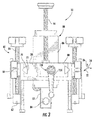
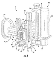
- FIGS. 1 and 7 illustrate various embodiments of a tool 10 according to the present disclosure mounted to a dovetail 12.
- the dovetail 12 as shown is a component of a rotor wheel 14 of a turbomachine, such as a steam turbine system or gas turbine system.
- the dovetail 12 includes a plurality of tangs 15 and hooks 16. In particular, pairs of opposing tangs 15 and hooks 16 are illustrated.
- a dovetail 12 may include any suitable number of hooks 16, and in particular may include any suitable number of opposing pairs of hooks 16.
- the dovetail 12, and the hooks 16 and tangs 15 thereof, generally extends circumferentially about at least a portion of the rotor wheel 14 circumference. It should be understood that the present disclosure is not limited to dovetails 12 on rotor wheels 14. Rather, any suitable dovetail 12 having one or more pairs of opposing tangs 15 and/hooks 16 is within the scope of the present disclosure.
- FIGS. 1 through 10 illustrate various embodiments of a tool 10 for machining a dovetail 12.
- the tool 10 may be generally mounted to the dovetail 12 and then moved along the dovetail 12, such as in a generally circumferential direction. During movement, the tool 10 may machine a tang 15 of the dovetail 12. Such machining may provide the tangs 15 with generally uniform shapes and sizes. In the case of dovetails 12 on rotor wheels 14, this facilitates the use of a plurality of buckets having generally consistently sized dovetail cavities with the dovetail 12. Machining of dovetails 12 using a tool 10 and/or method according to the present disclosure is efficient, accurate, and inexpensive relative to previously known tools and methods.
- a tool 10 includes a main body 20.
- Various other components of the tool 10 may be connected to the body 20.
- the body 20 may be a singular component, as shown in FIGS. 1 through 6 , or a plurality of distinct components, as shown in FIGS. 7 through 10 .
- the body 20 may further define various axes along or about which various other components of the tool 12 may move. As shown, an x-axis 22, a y-axis 24, and a z-axis 26 may be defined for the body 20.
- the tool 10 may further include a plurality of mount brackets 30.
- Each mount bracket 30 may be connected to the tool 10, and may be positionable in contact with a mount surface 32 of the dovetail 12.
- a crush surface 32 in exemplary embodiments is an underside of a hook 16. It should be understood, however, that any suitable surface of the dovetail 12 to which a mount bracket 30 may be placed in contact is within the scope of the present disclosure.
- the crush surfaces 32 generally serve as datums, or points of reference, for the tool 10 as the tool 10 is mounted to the dovetail 12, adjusted, and operated to machine the dovetail 12.
- a mount bracket 30 may include a body 34 and a mount surface 36.
- the body 34 may extend longitudinally generally along the z-axis 26 relative to the main body 20.
- a tool 10 may include a plurality of mount brackets 30.
- the mount brackets 30 may be spaced apart from one another along the x-axis 22.
- each mount bracket 30, such as the mount surface 36 thereof may be positioned in contact with a crush surface 32 of the dovetail 12.
- one or more mount brackets 30 may be positioned in contact with each of opposing crush surfaces 32 of the plurality of hooks 16. Such positioning of each mount bracket 30 in contact with a crush surface 32 allows the tool 10 to consistently machine the dovetail 12 during operation thereof.
- the crush surfaces 32 may be generally curvilinear.
- the mount surface 36 of each mount bracket 30 may be generally curvilinear.
- Such curvilinear shape allows the mount surface 36 to easily ride along the crush surface 32 with which it is in contact during movement of the tool 10 along the dovetail 12.
- the crush surface 32 may be generally linear, have linear and curvilinear portions, or have any other suitable shape.
- a mount bracket 30 according to the present disclosure may further be adjustable along one or more axes.
- a mount bracket 30 may be adjustable along the x-axis 22 or the y-axis 24.
- a mount bracket 30 may include a key member 40.
- the body 20 may define a corresponding keyway 42.
- the key member 40 and keyway 42 may have any suitable corresponding shapes and sizes, such that the key member 40 can slide within the corresponding keyway 42.
- a key member 40 may have a generally trapezoidal cross-sectional shape.
- a key-member 40 may have a generally rectangular cross-sectional shape.
- the corresponding keyway 42 may have a corresponding cross-sectional shape.
- a keyway 42 may extend generally longitudinally along the x-axis 22 or the y-axis 24.
- the key member 40 may thus be allowed to slide within the keyway 42 along the x-axis 22 or y-axis 24, thus adjusting the mount bracket 30 along the x-axis 22 or y-axis 24.
- any suitable adjustment mechanism which may allow a mount bracket 30 to be adjusted as required is within the scope of the present disclosure.
- a mount bracket 30 may additionally be adjustable along the z-axis 26.
- a mount bracket 30 may be adjustably connected to the included key member 40 by a male connector 44 of the key member 40 disposed in a corresponding female connection channel 46 of the mount bracket 30.
- the connector 44 may be movable within the channel 46 generally along the z-axis 26.
- the mount bracket 30 may be adjusted along the z-axis 26 via movement of the channel 46 relative to the connector 44.
- any suitable adjustment mechanism which may allow a mount bracket 30 to be adjusted as required is within the scope of the present disclosure.
- a mount bracket 30 may be adjusted along one or more axes.
- a mount bracket 30 may further include a locking assembly 50.
- the locking assembly 50 may be configured to selectively restrict adjustment of the mount bracket 30 along one or more of these axes.
- a locking assembly 50 may include a screw 52 connected to the key member 40.
- the screw 52 may be tightened relative to the key member 40, forcing the key member 40 against the corresponding keyway 42. Such force may cause sufficient friction between the key member 40 and keyway 42 to prevent to the key member 40 from moving within the keyway 42, thus restricting adjustment of the mount bracket 30 until the screw 52 is loosened.
- a knob 54 may be connected to the screw 52 to facilitate tightening and loosening thereof.
- any suitable locking mechanism which may allow adjustment of a mount bracket 30 to be restricted as required is within the scope of the present disclosure.
- a tool 10 may be mounted to a dovetail 12 by initially positioning the mount brackets 30 in contact with crush surfaces 32 of the dovetail 12. The mount brackets 30 may be then forced against the crush surfaces 32 such that each mount bracket 30 forcibly engages the crush surface 32 with which it is in contact.
- one or more engagement members 60 each of which may be connected to the body 20, may be positionable in contact with the dovetail 12. Further, each engagement member 60 may be adjustable such that contact by that engagement member 60 with the dovetail 12 forces one or more mount brackets 30 against the associated crush surface(s) 32. Such adjustment and resulting force may be generally along the z-axis 26, such that the mount brackets 30 are forced against the associated crush surfaces 32 generally along the z-axis.
- Such forcible contact and engagement caused by the engagement members 60 may effectively clamp the tool 10 to the dovetail 12.
- the amount of force utilized may be adjusted such that the tool 10 can, while forcibly engaging the dovetail 12, move along the dovetail 12 to consistently machine the dovetail 12 as required and discussed herein.
- an engagement member 60 includes a roller 62, a bracket 64, and a screw 66.
- the roller 62 may contact the dovetail 12, such as a top or outer surface 68 thereof, and may facilitate movement of the tool 10 along the dovetail 12 during machining.
- the screw 66 may be adjustable relative to the body 20, such as along the z-axis 26, to apply a force against the dovetail 12, thus forcing the mount brackets 30 against the crush surfaces 32.
- the bracket 64 may connect the engagement member 60 to the body 20, and the screw 66 may be connected to the bracket 64 and the roller 62.
- Adjustment of the screw 66 along the z-axis 26 may move the screw 66 relative to the body 20 and the bracket 64, and may additionally move the roller 62. After the mount brackets 30 are positioned in contact with the crush surfaces 32, the screw 66 may be adjusted such that the roller 62 contacts and is forced against the dovetail 12, further forcing the mount brackets 30 into forcible engagement with the mount crush 32.
- an engagement member 60 may further include a spring 69, as shown in FIGS. 7 through 10 .
- the spring 69 may be generally resilient in a direction along which force is applied by the engagement member 60, such as along the z-axis 26. Such resilience may thus provide an additional force, further engaging the mount brackets 30 in forcible contact with the crush surfaces 32.
- engagement members 60 are not limited to those including rollers 62, brackets 64, and/or screws 66 as discussed above. Rather, any suitable mechanism for engaging the tool 10 with the dovetail 12 as discussed above, such as suitable clamping mechanisms and/or forcing applying mechanisms, are within the scope of the present disclosure. As such, any suitable means for forcibly engaging each of the plurality of mount brackets 30 with the respective crush surfaces 32 is within the scope of the present disclosure.
- An engagement member 60 may be adjustable along one or more axes. As discussed, an engagement member 60 may be adjustable along the z-axis. Further, in exemplary embodiments, an engagement member 60 may be adjustable along the x-axis 22 or the y-axis 24. As shown in FIGS. 1 through 3 , 5 through 8 , and 10 , for example, an engagement member 60 may include a key member 70.
- the body 20 may define a corresponding keyway 72, which may be the same as or different from a keyway 42.
- the key member 70 and keyway 72 may have any suitable corresponding shapes and sizes, such that the key member 70 can slide within the corresponding keyway 72. In some exemplary embodiments, as shown in FIGS.
- a key member 70 may have a generally trapezoidal cross-sectional shape.
- a key-member 70 may have a generally rectangular cross-sectional shape.
- the corresponding keyway 72 may have a corresponding cross-sectional shape.
- a keyway 72 may extend generally longitudinally along the x-axis 22 or the y-axis 24. The key member 70 may thus be allowed to slide within the keyway 72 along the x-axis 22 or y-axis 24, thus adjusting the engagement member 60 along the x-axis 22 or y-axis 24.
- any suitable adjustment mechanism which may allow an engagement member 60 to be adjusted as required is within the scope of the present disclosure.
- an engagement member 60 may further include a locking assembly (not shown).
- the locking assembly may be configured to selectively restrict adjustment of the engagement member 60 along one or more of axes, as discussed above with respect to the mount brackets 30.
- the locking assembly may include a screw connected to a key member 60, as well as a knob, as discussed above with respect to the mount brackets 30 and key members 40.
- any suitable adjustment mechanism which may allow adjustment of an engagement member 60 to be restricted as required is within the scope of the present disclosure.
- a tool 10 may include one or more machining assemblies 80.
- a machining assembly 80 may be provided for machining tangs 15 of the dovetail 12, and may be connected to the body 20.
- the machining assembly 80 may be operated to machine a tang 15. During operation, the machining assembly 80 may grind or otherwise remove portions of the tang 15, including high spots, warps, etc.
- the tool 10 may be moved along the dovetail 12, such as in a generally circumferential or longitudinal direction along the dovetail 12, such that the tang 15 is consistently machined in the desired direction. This may provide the tang 15 with a consistent shape and size, as desired. Further, in exemplary embodiments, after machining of a tang 15, the tool 10 may be dismounted from the dovetail 12, opposedly remounted to the dovetail 12 by reversing the direction that the tool 10 is facing (for example, approximately 180 degrees about the z-axis) and remounting the tool 10 to the dovetail 12, and machining an opposing tang 15 to the tang 15 that was previously machined. This allows both of the opposing tangs 15 to have consistent sizes and shapes, which may be particularly advantageous when, for example, forming or adjusting dovetail channels to correspond to the dovetail 12 and tangs 15 thereof.
- a machining assembly 80 may include, for example, a grinder 82 and an abrasive 84.
- the grinder 82 may be any suitable component operable to rotate or otherwise move the abrasive 84.
- pneumatic, hydraulic, gear and/or motor driven grinders may be utilized.
- the abrasive 84 may connected to and rotated or otherwise moved by the grinder 82 to, when in contact with a tang 15, grind or otherwise machine the tang 15.
- Any suitable abrasive material such as sandpaper, metal, stone, ceramic, or another suitable material, may be utilized.
- machining assemblies 80 are not limited to those including grinders 82 and abrasives 84 as discussed above. Rather, any suitable mechanism for machining the dovetail 12 as discussed above, such as suitable sanding, polishing, or otherwise machining mechanisms, are within the scope of the present disclosure. As such, any suitable means for machining a tang 15 of a dovetail 12 is within the scope of the present disclosure.
- the abrasive 84 may be positionable in contact with a tang 15.
- the machining assembly 80 may be adjustable such that the abrasive contacts 84 the tang 15 to be machined.
- the machining assembly 80 may further include a bracket 86.
- the bracket 86 may connect the grinder 82, and thus the abrasive 84, to the body 20.
- the bracket 86 may be adjustable relative to the body 20, such that the abrasive 84 can be adjusted.
- the bracket 86 may be adjustable along the z-axis 26.
- the machining assembly 80 may include a key member 90, which may be integral with the bracket 86 as shown or separate from the bracket 86.
- the body 20 may define a corresponding keyway 92.
- the key member 90 and keyway 92 may have any suitable corresponding shapes and sizes, such that the key member 90 can slide within the corresponding keyway 92.
- a key member 90 may have a generally triangular cross-sectional shape.
- an opposing key member 90 may additionally have a triangular cross-sectional shape, giving the overall bracket 86 a generally trapezoidal shape.
- the corresponding keyway 92 may have a corresponding cross-sectional shape.
- a keyway 92 may extend generally longitudinally along the z-axis 26.
- the key member 90 may thus be allowed to slide within the keyway 92 along the z-axis 26, thus adjusting the machining assembly 80 along the z-axis 26.
- any suitable adjustment mechanism which may allow a machining assembly 80 to be adjusted as required is within the scope of the present disclosure.
- a screw 94 may further be included in a machining assembly 80 for adjusting the machining assembly 80 relative to the body 20.
- the screw 94 may extend longitudinally generally along the z-axis 26.
- the screw 94 may further connect the bracket 86 and body 20. Rotation of the screw 94 may move the bracket 86 along the z-axis 26 relative to the body 20, thus facilitating adjustment of the machining assembly 80 in general.
- a machining assembly 80 may be adjusted along one or more axes.
- a machining assembly 80 may further include a locking assembly 100.
- the locking assembly 100 may be configured to selectively restrict adjustment of the machining assembly 80 along one or more of these axes.
- a locking assembly 100 may include a screw 102 that presses against the bracket 86. The screw 102 may be tightened relative to the bracket 86 and optional key members 90 thereof, forcing the bracket 86 against the body 20, such as against the corresponding keyway 92.
- Such force may cause sufficient friction between the bracket 86 and body 20 to prevent to the bracket 86 from moving, such as within the keyway 92, thus restricting adjustment of the machining assembly 80 until the screw 102 is loosened.
- a knob 104 may be connected to the screw 102 to facilitate tightening and loosening thereof.
- any suitable locking mechanism which may allow adjustment of a machining assembly 80 to be restricted as required is within the scope of the present disclosure.
- a tool 10 may further include one or more handles 110.
- a handle 110 may be connected to the body 20, and may allow an operator to easily grasp and move the tool 10 during operation to machine the dovetail 12.
- a method may include, for example, mounting a plurality of mount brackets 30 in forcible contact with one or more crush surfaces 32 of the dovetail 12. Such mounting may include, for example, positioning each of the plurality of mount brackets 30 in contact with the crush surface 32 of the dovetail 12, and forcing each of the plurality of mount brackets 30 against the crush surface 32 of the dovetail 12, as discussed above.
- a method may further include, for example, positioning a machining assembly 80 in contact with one of the plurality of tangs 15 of the dovetail 12. Such positioning may include, for example, adjusting the machining assembly 80 along a z-axis 26, as discussed above.
- a method may further include, for example, moving the machining assembly 80 along the dovetail 12 while generally maintaining the forcible contact between the plurality of mount brackets 30 and the crush surfaces 32, as discussed above.
- a method according to the present disclosure may further include adjusting each of the plurality of mount brackets 30 along one of an x-axis 22 and a y-axis 24, as discussed above. Further, a method may in some embodiments include selectively restricting adjustment of each of the plurality of mount brackets 30 along the one of the x-axis 22 and the y-axis 24, as discussed above.
- a method according to the present disclosure may further include, for example, selectively restricting adjustment of the machining assembly 80 along the z-axis 26, as discussed above.
- a method may further include, for example, dismounting the plurality of mount brackets 30 from the crush surfaces 32 of the dovetail 12, opposedly remounting the plurality of mount brackets 30 in forcible contact with the crush surfaces 32 of the dovetail 12, positioning the machining assembly 80 in contact with an opposite one of the plurality of tangs 15 of the dovetail 12, andmoving the machining assembly 80 along the dovetail 12 while generally maintaining the forcible contact between the plurality of mount brackets 30 and the crush surface 32, as discussed above.
Landscapes
- Engineering & Computer Science (AREA)
- Mechanical Engineering (AREA)
- Machine Tool Units (AREA)
Applications Claiming Priority (1)
| Application Number | Priority Date | Filing Date | Title |
|---|---|---|---|
| US13/679,106 US20140141697A1 (en) | 2012-11-16 | 2012-11-16 | Tool and method for machining a dovetail |
Publications (1)
| Publication Number | Publication Date |
|---|---|
| EP2732908A2 true EP2732908A2 (fr) | 2014-05-21 |
Family
ID=49546265
Family Applications (1)
| Application Number | Title | Priority Date | Filing Date |
|---|---|---|---|
| EP13191351.9A Withdrawn EP2732908A2 (fr) | 2012-11-16 | 2013-11-04 | Outil et procédé d'usinage d'une queue d'aronde |
Country Status (2)
| Country | Link |
|---|---|
| US (1) | US20140141697A1 (fr) |
| EP (1) | EP2732908A2 (fr) |
Cited By (1)
| Publication number | Priority date | Publication date | Assignee | Title |
|---|---|---|---|---|
| CN110125701A (zh) * | 2019-05-10 | 2019-08-16 | 中国航发航空科技股份有限公司 | 一种工装夹具及装夹航空发动机涡轮精铸叶片的方法 |
Families Citing this family (3)
| Publication number | Priority date | Publication date | Assignee | Title |
|---|---|---|---|---|
| US20130232792A1 (en) * | 2012-03-12 | 2013-09-12 | General Electric Company | Apparatus and method for servicing turbomachinery components in-situ |
| CN111843683B (zh) * | 2020-07-26 | 2021-06-15 | 王小珍 | 一种机械配件的自动化磨毛边设备 |
| DE102021204878A1 (de) * | 2021-05-12 | 2022-11-17 | Robel Bahnbaumaschinen Gmbh | Schienen-Schleifmaschine und Verfahren zum Schleifen von Schienen eines Gleises |
Family Cites Families (9)
| Publication number | Priority date | Publication date | Assignee | Title |
|---|---|---|---|---|
| US1506504A (en) * | 1921-12-14 | 1924-08-26 | Joseph B Ruatti | Machine for finishing journal frames |
| DE2210909C2 (de) * | 1972-03-07 | 1982-12-23 | Horst 3000 Hannover Schulze | Einrichtung zum Trennen von Rohren |
| JPS60194152A (ja) * | 1984-03-09 | 1985-10-02 | 株式会社木地金筬製作所 | 空気噴射式織機の金筬研磨方法および装置 |
| US4914872A (en) * | 1987-05-22 | 1990-04-10 | United Technologies Corporation | Apparatus and method for selectively contouring an airfoil root |
| FR2713122B3 (fr) * | 1993-11-30 | 1996-03-15 | Cogest Sarl | Dispositif de grattage pour tubes. |
| US5512011A (en) * | 1994-10-28 | 1996-04-30 | Hudson Products Corporation | Cover plate header tongue and groove grinding/polishing machine |
| DE29913339U1 (de) * | 1999-07-30 | 1999-12-16 | Siemens AG, 80333 München | Schleifvorrichtung zum Bearbeiten von Höhendifferenzen an Stoßstellen von Stromschienen |
| US7328496B2 (en) * | 2003-10-31 | 2008-02-12 | General Electric Company | Apparatus for rebuilding gas turbine engine blades |
| US7665338B2 (en) * | 2006-10-20 | 2010-02-23 | Sonats-Societe Des Nouvelles Applications Des Techniques De Surfaces | Shot peening methods and units |
-
2012
- 2012-11-16 US US13/679,106 patent/US20140141697A1/en not_active Abandoned
-
2013
- 2013-11-04 EP EP13191351.9A patent/EP2732908A2/fr not_active Withdrawn
Non-Patent Citations (1)
| Title |
|---|
| None |
Cited By (1)
| Publication number | Priority date | Publication date | Assignee | Title |
|---|---|---|---|---|
| CN110125701A (zh) * | 2019-05-10 | 2019-08-16 | 中国航发航空科技股份有限公司 | 一种工装夹具及装夹航空发动机涡轮精铸叶片的方法 |
Also Published As
| Publication number | Publication date |
|---|---|
| US20140141697A1 (en) | 2014-05-22 |
Similar Documents
| Publication | Publication Date | Title |
|---|---|---|
| US9623492B2 (en) | Milling tool for portion of slot in rotor | |
| CA2865328C (fr) | Outil de profilage in situ de profils aerodynamiques | |
| US6302625B1 (en) | Method and apparatus for refurbishing a gas turbine airfoil | |
| US10717139B2 (en) | Method for manufacturing a rotor | |
| CA1130546A (fr) | Appareil et methode de refinition du joint etanche entre enveloppe et aubage de turbine | |
| US20100293786A1 (en) | Method and apparatus for rebuilding gas turbine engines | |
| EP2732908A2 (fr) | Outil et procédé d'usinage d'une queue d'aronde | |
| CN104551942B (zh) | 用于缩短流体机械的转子叶片的方法和设备 | |
| CN112059735A (zh) | 一种密封组件活塞环铸造成型加工机械及成型加工工艺 | |
| EP3072622B1 (fr) | Fixation pour électrode d'usinage électrochimique | |
| EP1955812B1 (fr) | Usinage d'une caractéristique de lame | |
| EP3184220A1 (fr) | Outil de fraisage portable avec procédé de fraisage de turbomachine | |
| KR102229550B1 (ko) | 2개의 부분으로 구성되어 조인트를 형성하는 터빈 하우징 내에 배열된 회전자를 기계 가공하기 위한 기계 가공 디바이스 및 방법, 및 터빈을 수리 및/또는 개조하기 위한 방법 | |
| CN213196966U (zh) | 一种泵轴合金环内缘打磨机 | |
| US20180021916A1 (en) | Surface finishing assembly | |
| CA2537334C (fr) | Appareil pour prendre en charge des formes aerodynamiques dans un procede de grenaillage | |
| CN209408153U (zh) | 一种密封环装配槽的磨削加工装置 | |
| CN223130394U (zh) | 一种砂轮的固定安装结构 | |
| US11059248B2 (en) | Expandable rim for tire tread buffing apparatus and method | |
| KR101114535B1 (ko) | 터빈로터의 버켓 외측단 가공방법 | |
| CN218137040U (zh) | 用于加工航空发动机的涡轮叶片的装置 | |
| CN219704627U (zh) | 一种倒角砂轮 | |
| CN210549288U (zh) | 一种转子汽封滚花刀 | |
| CN220660613U (zh) | 一种出口转向段工装 | |
| CN108326716B (zh) | 一种钻床驱动的薄片抛光机构及抛光方法 |
Legal Events
| Date | Code | Title | Description |
|---|---|---|---|
| PUAI | Public reference made under article 153(3) epc to a published international application that has entered the european phase |
Free format text: ORIGINAL CODE: 0009012 |
|
| 17P | Request for examination filed |
Effective date: 20131104 |
|
| AK | Designated contracting states |
Kind code of ref document: A2 Designated state(s): AL AT BE BG CH CY CZ DE DK EE ES FI FR GB GR HR HU IE IS IT LI LT LU LV MC MK MT NL NO PL PT RO RS SE SI SK SM TR |
|
| AX | Request for extension of the european patent |
Extension state: BA ME |
|
| STAA | Information on the status of an ep patent application or granted ep patent |
Free format text: STATUS: THE APPLICATION IS DEEMED TO BE WITHDRAWN |
|
| 18D | Application deemed to be withdrawn |
Effective date: 20160601 |