EP2732992A2 - Unité de soufflage pour véhicule - Google Patents
Unité de soufflage pour véhicule Download PDFInfo
- Publication number
- EP2732992A2 EP2732992A2 EP13192778.2A EP13192778A EP2732992A2 EP 2732992 A2 EP2732992 A2 EP 2732992A2 EP 13192778 A EP13192778 A EP 13192778A EP 2732992 A2 EP2732992 A2 EP 2732992A2
- Authority
- EP
- European Patent Office
- Prior art keywords
- damper
- introducing port
- vehicle
- air passage
- casing
- Prior art date
- Legal status (The legal status is an assumption and is not a legal conclusion. Google has not performed a legal analysis and makes no representation as to the accuracy of the status listed.)
- Withdrawn
Links
Images


Classifications
-
- B—PERFORMING OPERATIONS; TRANSPORTING
- B60—VEHICLES IN GENERAL
- B60H—ARRANGEMENTS OF HEATING, COOLING, VENTILATING OR OTHER AIR-TREATING DEVICES SPECIALLY ADAPTED FOR PASSENGER OR GOODS SPACES OF VEHICLES
- B60H1/00—Heating, cooling or ventilating devices
- B60H1/00642—Control systems or circuits; Control members or indication devices for heating, cooling or ventilating devices
- B60H1/00814—Control systems or circuits characterised by their output, for controlling particular components of the heating, cooling or ventilating installation
- B60H1/00821—Control systems or circuits characterised by their output, for controlling particular components of the heating, cooling or ventilating installation the components being ventilating, air admitting or air distributing devices
- B60H1/00835—Damper doors, e.g. position control
- B60H1/00849—Damper doors, e.g. position control for selectively commanding the induction of outside or inside air
-
- B—PERFORMING OPERATIONS; TRANSPORTING
- B60—VEHICLES IN GENERAL
- B60H—ARRANGEMENTS OF HEATING, COOLING, VENTILATING OR OTHER AIR-TREATING DEVICES SPECIALLY ADAPTED FOR PASSENGER OR GOODS SPACES OF VEHICLES
- B60H1/00—Heating, cooling or ventilating devices
- B60H1/00007—Combined heating, ventilating, or cooling devices
- B60H1/00021—Air flow details of HVAC devices
- B60H2001/00078—Assembling, manufacturing or layout details
- B60H2001/00085—Assembling, manufacturing or layout details of air intake
Definitions
- the present invention relates to a blower unit which is used in an air-conditioning device for a vehicle or the like, and introduces air into an air passage formed in the inside of a casing through an outside air introducing port and/or an inside air introducing port by operating a blower.
- a blower unit for a vehicle which includes: a casing which has an air passage in the inside thereof and is provided with an inside air introducing port and an outside air introducing port which are communicated with the air passage ; a rotary damper which is arranged in the air passage and opens or closes the inside air introducing port or the outside air introducing port; and a blower which introduces air into the inside of the air passage through the inside air introducing port and/or the outside air introducing port.
- an angle by which the rotary damper is rotatable is generally set to less than 180 degrees (approximately 150 degrees, for example).
- the movable angle range of the rotary damper is less than 180 degrees, the advantageous effect of making the flow of air uniform by the air flow guide portion of the rotary damper is limited.
- the smaller the movable angle range the larger a casing portion for covering the intake box becomes.
- an extra space that is, a space which is displaced from the direction of air which flows into the blower through the outside air introducing port or the inside air introducing port is formed.
- the extra space generates a vortex formed of air displaced from the direction of air which flows into the blower through the outside air introducing port or the inside air introducing port thus giving rise to a drawback such as noises generated by the blower unit for a vehicle or lowering of blasting efficiency.
- the blower unit for a vehicle includes: a casing which defines an air passage in the inside thereof, the casing provided with an inside air introducing port and an outside air introducing port which are communicated with the air passage; a damper which is arranged in the air passage and opens or closes the inside air introducing port or the outside air introducing port; and a blower which introduces air into the inside of the air passage through the inside air introducing port and/or the outside air introducing port, wherein the blower has a motor provided with a motor rotary shaft and a fan rotatably driven by the motor, and the air passage has a fan accommodating portion which is provided on a leeward side of the damper and accommodates the fan of the blower therein.
- the blower unit for a vehicle having such a constitution is characterized in that an inner surface of the casing ranging from a portion of the casing near an end of a movable range of the damper to a portion of the casing near an end of the fan accommodating portion on a windward side is formed in a flat surface or in a convex surface projecting toward the air passage (Claim 1).
- the number of inside air introducing ports may be one or plural, and the number of dampers may be also one or plural.
- the damper may be a rotary damper or a damper having a plate-shaped closure portion.
- the inner surface of the casing ranging from the portion of the casing near the end of the movable range of the damper to the portion of the casing near the end of the fan accommodating portion on a windward side is formed in a flat surface or in a convex surface projecting toward the air passage. Accordingly, an extra space displaced from the direction of air which flows toward the blower from the outside air introducing port or the inside air introducing port is not formed between a portion of the intake box on a leeward side of the damper and the fan accommodating portion and hence, the generation of a vortex in the air passage can be prevented.
- the blower unit for a vehicle includes: a casing which defines an air passage in the inside thereof, the casing provided with an inside air introducing port and an outside air introducing port which are communicated with the air passage; a damper which is arranged in the air passage and opens or closes the inside air introducing port or the outside air introducing port; and a blower which introduces air into the inside of the air passage through the inside air introducing port and/or the outside air introducing port, wherein the blower has a motor provided with a motor rotary shaft and a fan rotatably driven by the motor, and the air passage has a filter accommodating portion which is provided on a leeward side of the damper and accommodates a filter therein, and a fan accommodating portion which is provided on a leeward side of the filter accommodating portion and accommodates the fan of the blower therein.
- the blower unit for a vehicle having such a constitution is characterized in that an inner surface of the casing ranging from a portion of the casing near an end of a movable range of the damper to an end of the filter accommodating portion on a windward side is formed in a flat surface or in a convex surface projecting toward the air passage (Claim 2).
- the number of inside air introducing ports may be one or plural, and the number of dampers may be also one or plural.
- the damper may be a rotary damper or a damper having a plate-shaped closure portion.
- the inner surface of the casing ranging from the portion of the casing near an end of the movable range of the damper to the end of the filter accommodating portion on a windward side is formed in a flat surface or in a convex surface projecting toward the air passage. Accordingly, an extra space displaced from the direction of air which flows toward the blower from the outside air introducing port or the inside air introducing port is not formed between the portion of the intake box on a leeward side of the damper and the filter accommodating portion and hence, the generation of a vortex in the air passage can be prevented.
- the outside air introducing port may be arranged in the axial direction of the motor rotary shaft (Claim 3).
- the outside air introducing port is arranged in the axial direction of the motor rotary shaft and hence, outside air can be sucked into the fan linearly whereby the air flow resistance in an outside air introducing passage can be decreased.
- the damper may be a rotary damper which includes a damper rotary shaft, and a closure portion which is capable of closing the inside air introducing port or the outside air introducing port, and the closure portion may have a convex surface projecting toward the damper rotary shaft (Claim 4).
- the closure portion of the damper has the convex surface projecting toward the damper rotary shaft and hence, an extra space displaced from the direction of air which flows into the blower from the inside air introducing port or the outside air introducing port is further decreased whereby the generation of a vortex in the air passage can be prevented more reliably.
- the damper may be a rotary damper which includes a damper rotary shaft, and a closure portion which is capable of closing the inside air introducing port or the outside air introducing port, and a portion of the casing which is arranged near an end of a movable range of the rotary damper may have a seat surface which extends toward the inside of the air passage and with which the rotary damper is brought into contact, and an inner surface of the casing ranging from an end of the seat surface inside the air passage to a portion of the inner surface of the casing near an end of the fan accommodating portion on a windward side may be formed in a flat surface or in a convex surface projecting toward the air passage (Claim 5).
- the inner surface of the casing ranging from the end of the seat surface inside the air passage to the portion of the inner surface of the casing near the end of the fan accommodating portion on a windward side is formed in a flat surface or in a convex surface projecting toward the air passage. Accordingly, the extra space can be further decreased and hence, the generation of a vortex in the air passage can be prevented more reliably.
- the damper may be a rotary damper which includes a damper rotary shaft, and a closure portion which is capable of closing the inside air introducing port or the outside air introducing port, and a portion of the casing which is arranged near an end of a movable range of the rotary damper may have a seat surface which extends toward the inside of the air passage and with which the rotary damper is brought into contact, and an inner surface of the casing ranging from an end of the seat surface inside the air passage to an end of the filter accommodating portion on a windward side may be formed in a flat surface or in a convex surface projecting toward the air passage (Claim 6) .
- the inner surface of the casing ranging from the end of the seat surface inside the air passage to the end of the filter accommodating portion on a windward side is formed in a flat surface or in a convex surface projecting toward the air passage. Accordingly, the extra space can be further decreased and hence, the generation of a vortex in the air passage can be prevented more reliably.
- the inner surface of the casing ranging from the portion of the casing near the end of the movable range of the damper to the portion of the casing near the end of the fan accommodating portion on a windward side is formed in a flat surface or in a convex surface projecting toward the air passage. Accordingly, an extra space displaced from the direction of air which flows toward the blower from the outside air introducing port or the inside air introducing port is not formed in the intake box from a leeward side of the damper to the fan accommodating portion and hence, the generation of a vortex in the air passage can be prevented.
- the inner surface of the casing ranging from the portion of the casing near an end of the movable range of the damper to the end of the filter accommodating portion on a windward side is formed in a flat surface or in a convex surface projecting toward the air passage. Accordingly, an extra space displaced from the direction of air which flows toward the blower from the outside air introducing port or the inside air introducing port is not formed between the portion of the intake box on a leeward side of the damper and the filter accommodating portion and hence, the generation of a vortex in the air passage can be prevented.
- the outside air introducing port is arranged in the axial direction of the motor rotary shaft and hence, outside air can be sucked into the fan linearly whereby the air flow resistance in an outside air introducing passage can be decreased.
- the closure portion of the damper has the convex surface projecting toward the damper rotary shaft and hence, an extra space displaced from the direction of air which flows toward the blower from the inside air introducing port or the outside air introducing port can be further decreased whereby the generation of a vortex in the air passage can be prevented more reliably.
- the inner surface of the casing ranging from the end of the seat surface inside the air passage to the portion of the casing near the end of the fan accommodating portion on a windward side is formed in a flat surface or in a convex surface projecting toward the air passage. Accordingly, the extra space displaced from the direction of air which flows toward the blower from the inside air introducing port or the outside air introducing port can be further decreased and hence, the generation of a vortex in the air passage can be prevented more reliably.
- the inner surface of the casing ranging from the end of the seat surface inside the air passage to the end of the filter accommodating portion on a windward side is formed in a flat surface or in a convex surface projecting toward the air passage. Accordingly, the extra space displaced from the direction of air which flows toward the blower from the inside air introducing port or the outside air introducing port can be further decreased and hence, the generation of a vortex in the air passage can be prevented more reliably.
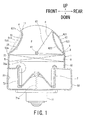
- Fig. 1 to Fig. 3 show a blower unit 1 for a vehicle according to a first embodiment which is provided with a filter accommodating portion 22.
- the blower unit 1 for a vehicle constitutes a part of an HVAC (Heating Ventilation and Air Conditioning) unit for a vehicle.
- the blower unit 1 for a vehicle includes: a casing 5 which defines an air passage 2 in the inside thereof, the casing 5 provided with an inside air introducing port 3 and an outside air introducing port 4 which are communicated with the air passage 2; a rotary damper 6 which is arranged in the air passage 2 and opens or closes the inside air introducing port 3 and the outside air introducing port 4; a blower 7 which introduces air into the inside of the air passage 2 through the inside air introducing port 3 and/or the outside air introducing port 4; and a filter 8 which is arranged on a leeward side of the rotary damper 6 and on a windward side of the blower 7.
- the air passage 2 is a passage in which the inside air introducing port 3 or the outside air introducing port 4 is formed on a windward side, and an air blow-off port which is connected to an air conditioning unit body arranged adjacent to the air passage 2 (neither the air conditioning unit body nor the air blow-off port shown in the drawings) is formed on a leeward side.
- the air passage 2 includes a damper accommodating portion 21 in which the rotary damper 6 is accommodated, a filter accommodating portion 22 in which the filter 8 is accommodated, and a fan accommodating portion 23 in which a fan 72 (described later) of the blower 7 is accommodated.
- the damper accommodating portion 21, the filter accommodating portion 22 and the fan accommodating portion 23 of the air passage 2 are arranged sequentially along the vertical direction of the vehicle.
- the inside air introducing port 3 is opened in the casing 5 not only upwardly in the vertical direction of the vehicle and on a rear side in the longitudinal direction of the vehicle but also on both sides in the lateral direction of the vehicle.
- the rotary damper 6 includes a damper rotary shaft 61, a closure portion 62, and a connecting portion 63 which contiguously connects the damper rotary shaft 61 and the closure portion 62 to each other.
- the closure portion 62 is movable within a predetermined angle range about the damper rotary shaft 61. The structure of the closure portion 62 is described later.
- the blower 7 includes a motor 71 having a motor rotary shaft 71a and a fan 72 which is rotatably driven by the motor 71.
- the fan 72 includes an intake port 72a which is opened toward a damper accommodating portion 21 side.
- the filter 8 is provided for removing foreign matters such as dusts from air which passes through the filter 8 and for removing odors.
- the filter 8 is arranged over the whole region of the filter accommodating portion 22.
- the filter 8 is formed in a flat plate shape having a small wall thickness.
- the filter 8 is arranged in a horizontally laid-down posture in the longitudinal direction of the vehicle.
- the casing 5 includes a portion 51 which forms an outer shell of the damper accommodating portion, a portion 52 which forms an outer shell of the filter accommodating portion, and a portion 53 which forms an outer shell of the fan accommodating portion.
- the portion 51 which forms the outer shell of the damper accommodating portion is a portion which is also referred to as an intake box.
- the portion 53 which forms the outer shell of the fan accommodating portion is formed in a scroll shape as viewed in the vertical direction of the vehicle.
- the air blow-off port arranged on a leeward side of the air passage 2 is opened at a distal end of the scroll.
- the outside air introducing port 4 is arranged in the axial direction of the motor rotary shaft 71a of the blower 7, and the inside air introducing port 3 is arranged behind the outside air introducing port 4 in the longitudinal direction of the vehicle.
- a contact portion 9 which extends toward the inside of the air passage 2 from an opening end of the inside air introducing port 3 on a filter accommodating portion 22 side is formed.
- the rotary damper 6 is brought into contact with the contact portion 9 when the rotary damper 6 closes the inside air introducing port 3. That is, a position where the rotary damper 6 is brought into contact with the contact portion 9 defines one end of a movable range of the rotary damper 6.
- the portion 51 of the casing which forms the outer shell of the damper accommodating portion has a wall portion 511 which contiguously connects an end portion of the outside air introducing port 4 and an end portion 52a of the filter accommodating portion 52 on a windward side to each other.
- An end portion of the outside air introducing port 4 has, in the vicinity thereof, a portion 511a which is arranged near a front end of the movable range of the rotary damper in the longitudinal direction of the vehicle.
- a seat surface 11 which extends toward the inside of the air passage 2 and with which the rotary damper 6 is brought into contact is formed.
- the seat surface 11 is formed by forming a stepped portion on the portion 51 which forms the outer shell of the damper accommodating portion of the casing.
- An end of the seat surface 11 inside the air flow passage also functions as the portion 511a which is arranged near the front end of the movable range of the rotary damper in the longitudinal direction of the vehicle.
- the wall portion 511 is contiguously formed ranging from the end of the seat surface 11 inside the air passage 2 (the portion 511a arranged near the front end of the movable range of the rotary damper in the longitudinal direction of the vehicle) to the end portion 52a of the filter accommodating portion on a windward side.
- the wall portion 511 has a small wall thickness and is bent in an arcuate shape. Accordingly, an inner surface of the wall portion 511 ranging from the end of the seat surface 11 inside the air passage 2 to the end portion 52a of the filter accommodating portion on a windward side is formed in a convex curved surface projecting toward the air passage 2.
- the wall portion 511 may be formed in a convex surface projecting toward the air passage 2.
- the wall portion 511 may be formed in a flat surface.
- an inner surface of the wall portion 511 may be formed in a convex surface projecting toward the air passage 2 or in a flat surface as described above.
- a convex surface projecting toward the air passage 2 or a flat surface may be formed on the inner surface of the wall portion 511 ranging from an arbitrary position on the portion 511a arranged near the front end of the movable range of the rotary damper in the longitudinal direction of the vehicle to the end portion 52a of the filter accommodating portion of the casing on a windward side.
- the inner surface of the wall portion 511 which faces the air passage 2 in a convex surface projecting toward the air passage 2 or in a flat surface, it is possible to prevent an extra space displaced from the direction of air which flows toward the blower 7 from the outside air introducing port 4 or the inside air introducing port 3 from being formed between a leeward side of the rotary damper 6 and the filter accommodating portion 22 in the air passage 2, that is, inside the damper accommodating portion 21 (intake box).
- the wall portion 511 in a convex surface projecting toward the air passage 2 the formation of the extra space can be further prevented.
- an amount of material for forming the casing can be further decreased.
- the closure portion 62 of the rotary damper 6 is constituted of an outer surface portion 621, an inner surface portion 622, and a hollow portion 623 which is surrounded by the outer surface portion 621 and the inner surface portion 622.
- the inner surface portion 622 of the closure portion has a convex surface projecting toward the damper rotary shaft 61. Due to such a constitution, in the air passage 2, an extra space displaced from the direction of air which flows toward the blower 7 from the outside air introducing port 4 or the inside air introducing port 3 can be further decreased. Further, as shown in Fig.
- a convex surface projecting toward the damper rotary shaft 61 which the inner surface portion 622 of the closure portion has is formed in symmetry with a convex surface projecting toward the air passage 2 which the wall portion 511 has when the closure portion 62 closes the inside air introducing port 3. Due to such a constitution, in the air passage 2, the flow of air which flows toward the blower 7 from the outside air introducing port 4 can be made more uniform thus preventing the generation of noises.
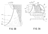
- Fig. 4 to Fig. 7 show characteristic curves indicating the flow of air which flows through the air passage 2 in the blower unit 1 for a vehicle which includes the above-mentioned filter accommodating portion 22 and is configured such that the convex surface projecting toward the air passage 2 is formed on the inner surface of the wall portion 511 and the convex surface projecting toward the damper rotary shaft is formed on the inner surface portion 622 of the rotary damper 6.
- Fig. 4 shows the flow of air near a right side surface or a left side surface of the blower unit 1 in the lateral direction of the vehicle in the outside air introducing mode
- Fig. 5 shows the flow of air near the center of the blower unit 1 in the lateral direction of the vehicle in the outside air introducing mode
- Fig. 4 shows the flow of air near a right side surface or a left side surface of the blower unit 1 in the lateral direction of the vehicle in the outside air introducing mode
- Fig. 5 shows the flow of air near the center of the blower unit 1 in the
- FIG. 6 shows the flow of air near the right side surface or the left side surface of the blower unit 1 in the lateral direction of the vehicle in the inside air introducing mode
- Fig. 7 shows the flow of air near the center of the blower unit 1 in the lateral direction of the vehicle in the inside air introducing mode.
- the inside air introducing port 3 is opened not only in the longitudinal direction of the vehicle but also on both sides in the lateral direction of the vehicle, and the inside air introducing port 3 is also opened up to a portion near the intake port 72a of the fan 72.
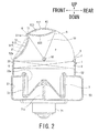
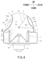
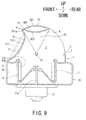
- blower unit 1 for a vehicle shown in Fig. 1 and Fig. 2 heretofore, it is not always necessary to apply the present invention to the blower unit 1 for a vehicle shown in Fig. 1 and Fig. 2 . That is, as shown in Fig. 8 and Fig. 9 , the present invention is also applicable to a blower unit 1 for a vehicle of a type not including a filter accommodating portion which is exemplified as a second embodiment.
- the blower unit 1 for a vehicle shown in Fig. 8 and Fig. 9 differs from the blower unit 1 for a vehicle shown in Fig. 1 and Fig. 2 with respect to a point that the blower unit 1 for a vehicle shown in Fig. 8 and Fig. 9 is not provided with the filter accommodating portion 22, that is, with respect to a point that a wall portion 511 of a casing 5 which is formed in a convex surface projecting toward an air passage 2 is contiguously formed ranging from an end of a seat surface 11 inside an air passage to an end portion 53a of a fan accommodating portion 23 of the casing 5 on a windward side.
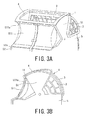
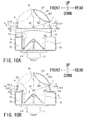
- Fig. 10 to Fig. 12 show, out of blower units 1 for a vehicle according to the present invention, blower units 1 for a vehicle of a third embodiment each of which includes a wall portion 511 and a wall portion 512.
- blower unit 1 for a vehicle shown in each drawing is explained.
- the constitutions of the blower unit 1 of the third embodiment substantially equal to the constitutions of the blower unit 1 for a vehicle shown in Fig. 1 and Fig. 2 or the constitutions of the blower unit 1 for a vehicle shown in Fig. 8 and Fig. 9 are given the same symbols and their repeated explanation is omitted.
- an outside air introducing port 4 is arranged in front of a damper rotary shaft 61 in the longitudinal direction of the vehicle, and an inside air introducing port 3 is arranged behind the damper rotary shaft 61 in the longitudinal direction of the vehicle.
- a portion 51 which forms an outer shell of a damper accommodating portion of a casing includes: the wall portion 511 which contiguously connects a portion 511a near a front end of a movable range of a rotary damper in the longitudinal direction of the vehicle and an end portion 52a of a filter accommodating portion of the casing on a windward side to each other; and the wall portion 512 which contiguously connects a portion 512a near a rear end of the movable range of the rotary damper in the longitudinal direction of the vehicle and an end portion 52a of a filter accommodating portion of the casing on a windward side to each other.
- the portion 511a near the front end of the movable range of the rotary damper in the longitudinal direction of the vehicle and the end portion 52a of the filter accommodating portion of the casing on a windward side are positioned along the approximately perpendicular direction in the vertical direction of the vehicle, and the portion 512a near the rear end of the movable range of the rotary damper in the longitudinal direction of the vehicle and the end portion 52a of the filter accommodating portion of the casing on a windward side are positioned along the approximately perpendicular direction in the vertical direction of the vehicle.
- the wall portions 511, 512 have a small wall thickness and are bent in an arcuate shape and hence, inner surfaces of the wall portions 511, 512 which face an air passage 2 are formed in a convex curved surface projecting toward the air passage 2 respectively.
- the convex surface projecting toward the air passage 2 which the wall portion 511 has and the convex surface projecting toward the air passage 2 which the wall portion 512 has are arranged in symmetry.
- a portion 51 which forms an outer shell of a damper accommodating portion of a casing includes: a wall portion 511 which contiguously connects a portion 511a near a front end of a movable range of a rotary damper in the longitudinal direction of a vehicle and an end portion 53a of a fan accommodating portion of a casing on a windward side to each other; and a wall portion 512 which contiguously connects a portion 512a near a rear end of the movable range of the rotary damper in the longitudinal direction of the vehicle and an upper surface portion 53b of the fan accommodating portion of the casing to each other.
- the portion 511a near the front end of the movable range of the rotary damper in the longitudinal direction of the vehicle and the end portion 53a of the fan accommodating portion of the casing 5 on a windward side are positioned along the approximately perpendicular direction in the vertical direction of the vehicle, and the portion 512a near the rear end of the movable range of the rotary damper in the longitudinal direction of the vehicle and the upper surface portion 53b of the fan accommodating portion of the casing are positioned along the approximately perpendicular direction in the vertical direction of the vehicle.
- FIG. 10B also have a small wall thickness and are bent in an arcuate shape and hence, inner surfaces of the wall portions 511, 512 which face an air passage 2 are formed in a convex curved surface projecting toward the air passage 2 respectively. Also in Fig. 10B , the convex surface projecting toward the air passage 2 which the wall portion 511 has and the convex surface projecting toward the air passage 2 which the wall portion 512 has are arranged in symmetry.
- an inside air introducing port 3 is arranged from a position above a damper rotary shaft 61 in the vertical direction of the vehicle to a position behind the damper rotary shaft 6 in the longitudinal direction of the vehicle, and an outside air introducing port 4 is arranged in front of the damper rotary shaft 61 in the longitudinal direction of the vehicle. That is, the outside air introducing port 4 and the inside air introducing port 3 of the blower unit 1 for a vehicle shown in Fig. 11A and Fig.
- FIG. 11B are arranged at positions displaced frontward in the longitudinal direction of the vehicle compared to the outside air introducing port 4 and the inside air introducing port 3 of the blower unit 1 for a vehicle shown in Fig. 10A and Fig. 10B as a whole.
- the blower unit 1 for a vehicle of a type including a filter accommodating portion shown in Fig. 11A is substantially equal to the blower unit 1 for a vehicle of a type including the filter accommodating portion shown in Fig. 10A with respect to the point that the portion 51 which forms the outer shell of the damper accommodating portion of the casing includes: the wall portion 511 which contiguously connects the portion 511a near the front end of the movable range of the rotary damper in the longitudinal direction of the vehicle and the end portion 52a of the filter accommodating portion of the casing on a windward side to each other; and the wall portion 512 which contiguously connects the portion 512a near the rear end of the movable range of the rotary damper in the longitudinal direction of the vehicle and the end portion 52a of the filter accommodating portion of the casing on a windward side to each other.
- the portion 511a near the front end of the movable range of the rotary damper in the longitudinal direction of the vehicle and the end portion 52a of the filter accommodating portion of the casing on a windward side are arranged in an obliquely displaced manner from each other in the longitudinal direction of the vehicle
- the portion 512a near the rear end of the movable range of the rotary damper in the longitudinal direction of the vehicle and the end portion 52a of the filter accommodating portion of the casing 5 on a windward side are arranged in an obliquely displaced manner from each other in the longitudinal direction of the vehicle.
- the wall portions 511, 512 which face an air passage have a small wall thickness and are bent in an arcuate shape and hence, inner surfaces of the wall portions 511, 512 are formed in a convex curved surface projecting toward the air passage 2 respectively.
- the blower unit 1 for a vehicle of a type not including a filter accommodating portion shown in Fig. 11B is substantially equal to the blower unit 1 for a vehicle of a type including the filter accommodating portion shown in Fig. 10B with respect to the point that the portion 51 which forms the outer shell of the damper accommodating portion of the casing includes: the wall portion 511 which contiguously connects the portion 511a near the front end of the movable range of the rotary damper in the longitudinal direction of the vehicle and the end portion 53a of the fan accommodating portion of the casing on a windward side to each other; and the wall portion 512 which contiguously connects the portion 512a near the rear end of the movable range of the rotary damper in the longitudinal direction of the vehicle and the upper surface portion 53b of the fan accommodating portion of the casing to each other.
- the portion 511a near the front end of the movable range of the rotary damper in the longitudinal direction of the vehicle and the end portion 53a of the fan accommodating portion of the casing on a windward side are arranged in an obliquely displaced manner from each other in the longitudinal direction of the vehicle
- the portion 512a near the rear end of the movable range of the rotary damper in the longitudinal direction of the vehicle and the upper surface portion 53b of the fan accommodating portion of the casing 5 on a windward side are arranged in an obliquely displaced manner from each other in the longitudinal direction of the vehicle.
- the wall portions 511, 512 shown in Fig. 11B also have a small wall thickness and are bent in an arcuate shape and hence, inner surfaces of the wall portions 511, 512 which face an air passage 2 are formed in a convex curved surface projecting toward the air passage 2 respectively.
- the blower unit 1 for a vehicle shown in Fig. 12 includes a damper 10 having a damper rotary shaft 101 and a plate-shaped closure portion 102.
- the damper rotary shape 101 is arranged between an outside air introducing port 4 and an inside air introducing port 3, and the damper 10 is rotated about the damper rotary shaft 101. Due to such a constitution, the plate-shaped closure portion 102 can open or close the outside air introducing port 4 and the inside air introducing port 3.
- the blower unit 1 for a vehicle of a type including a filter accommodating portion shown in Fig. 12A is substantially equal to the blower unit 1 for a vehicle of a type including the filter accommodating portion shown in Fig. 10A with respect to the arrangement of wall portions 511, 512 and a point that inner surfaces of the wall portions 511, 512 are formed in a convex surface projecting toward an air passage 2.
- the blower unit 1 for a vehicle of a type not including the filter accommodating portion shown in Fig. 12B is substantially equal to the blower unit 1 for a vehicle of a type not including the filter accommodating portion shown in Fig. 10B with respect to the arrangement of the wall portions 511, 512 and a point that inner surfaces of the wall portions 511, 512 are formed in a convex surface projecting toward the air passage 2.
- Fig. 13 shows, out of the blower units 1 for a vehicle according to the present invention, a blower unit 1 for a vehicle of the fourth embodiment which includes two inside air introducing ports 3, 3, two outside air introducing ports 4, 4 and two dampers 10, 10.
- Each damper 10 includes a damper rotary shaft 101 and a plate-shaped closure portion 102.
- Each damper rotary shaft 101 is arranged between the inside air introducing port 3 and the outside air introducing port 4.
- the plate-shaped closure portions 102 can open or close the inside air introducing ports 3 and the outside air introducing ports 4.
- a wall portion 511 which contiguously connects a portion 511a near a front end of a movable range of the rotary damper in the longitudinal direction of the vehicle and an end portion of a filter accommodating portion of a casing on a windward side to each other
- a wall portion 512 which contiguously connects a portion 512a near a rear end of the movable range of the rotary damper in the longitudinal direction of the vehicle and an end portion of a filter accommodating portion of the casing on a windward side to each other.
- the wall portions 511, 512 have a small wall thickness and are bent in an arcuate shape and hence, inner surfaces of the wall portions 511, 512 which face an air passage 2 are formed in a convex surface projecting toward the air passage 2 respectively.
- the convex surface projecting toward the air passage 2 which the wall portion 511 has and the convex curved surface projecting toward the air passage 2 which the wall portion 512 has are arranged in symmetry.
- blower unit 1 for a vehicle of a type including the filter accommodating portion is shown.
- a blower unit 1 for a vehicle of a type not including a filter accommodating portion is also substantially equal to the blower unit 1 for a vehicle of a type including a filter accommodating portion with respect to a point that inner surfaces are formed in a convex surface projecting toward an air passage 2 although both blower units 1 differ from each other only with respect to a point that, in the blower unit 1 for a vehicle of a type not including a filter accommodating portion, lower sides of wall portions 511, 512 are contiguously connected to an end portion of a fan accommodating portion of a casing on a windward side and an upper surface portion of a fan accommodating portion of the casing respectively.
- the blower unit 1 for a vehicle has been explained heretofore in the form that the blower unit 1 constitutes a part of an HVAC unit for a vehicle
- the blower unit for a vehicle according to the present invention is not limited to the blower unit which forms a part of the HVAC unit.
- the blower unit for a vehicle according to the present invention may be a blower unit which forms a part of a ventilation device for a vehicle which can ventilate a cabin of a vehicle or may be a blower unit which forms a part of a battery cooling device for a vehicle which cools a battery of an electric automobile by supplying air to the battery.
Landscapes
- Physics & Mathematics (AREA)
- Thermal Sciences (AREA)
- Engineering & Computer Science (AREA)
- Mechanical Engineering (AREA)
- Air-Conditioning For Vehicles (AREA)
- Structures Of Non-Positive Displacement Pumps (AREA)
Applications Claiming Priority (1)
| Application Number | Priority Date | Filing Date | Title |
|---|---|---|---|
| JP2012251212A JP6139110B2 (ja) | 2012-11-15 | 2012-11-15 | 車両用送風装置 |
Publications (2)
| Publication Number | Publication Date |
|---|---|
| EP2732992A2 true EP2732992A2 (fr) | 2014-05-21 |
| EP2732992A3 EP2732992A3 (fr) | 2017-12-20 |
Family
ID=49666944
Family Applications (1)
| Application Number | Title | Priority Date | Filing Date |
|---|---|---|---|
| EP13192778.2A Withdrawn EP2732992A3 (fr) | 2012-11-15 | 2013-11-13 | Unité de soufflage pour véhicule |
Country Status (3)
| Country | Link |
|---|---|
| EP (1) | EP2732992A3 (fr) |
| JP (1) | JP6139110B2 (fr) |
| CN (1) | CN103818215B (fr) |
Families Citing this family (3)
| Publication number | Priority date | Publication date | Assignee | Title |
|---|---|---|---|---|
| CN104501382B (zh) * | 2014-12-19 | 2018-04-13 | 安徽江淮汽车集团股份有限公司 | 一种汽车空调风门结构 |
| US10479161B2 (en) * | 2016-01-18 | 2019-11-19 | Hanon Systems | Vehicle air-conditioning system |
| WO2022230759A1 (fr) * | 2021-04-28 | 2022-11-03 | 株式会社ヴァレオジャパン | Dispositif de climatisation pour véhicule |
Citations (1)
| Publication number | Priority date | Publication date | Assignee | Title |
|---|---|---|---|---|
| JPH09156345A (ja) | 1995-12-05 | 1997-06-17 | Denso Corp | 車両用空調装置 |
Family Cites Families (11)
| Publication number | Priority date | Publication date | Assignee | Title |
|---|---|---|---|---|
| JPS60151712U (ja) * | 1984-03-21 | 1985-10-08 | カルソニックカンセイ株式会社 | 自動車用空気調和装置のインテ−クユニツト |
| JP2000016052A (ja) * | 1998-07-03 | 2000-01-18 | Zexel Corp | 開閉ドア、ブロアユニット、ヒータユニット及びエアコンユニット |
| JP4164956B2 (ja) * | 1999-08-27 | 2008-10-15 | 株式会社デンソー | 車両用空調装置 |
| JP2001071737A (ja) * | 1999-09-08 | 2001-03-21 | Denso Corp | 車両用空調装置 |
| JP4310898B2 (ja) * | 2000-07-19 | 2009-08-12 | 株式会社デンソー | 車両用内外気切換装置 |
| JP4539434B2 (ja) * | 2005-05-17 | 2010-09-08 | 株式会社デンソー | 内外気切替装置およびその製造方法 |
| KR100756086B1 (ko) * | 2005-12-02 | 2007-09-05 | 모딘코리아 유한회사 | 차량용 공기조화기 |
| JP2007168735A (ja) * | 2005-12-26 | 2007-07-05 | Denso Corp | 空気通路切換装置および車両用空調装置の内外気切換装置 |
| KR100999134B1 (ko) * | 2006-10-25 | 2010-12-08 | 현대자동차주식회사 | 자동차 공기 조화기용 내외기 제어 방법 |
| DE102008053065A1 (de) * | 2008-10-24 | 2010-04-29 | Behr Gmbh & Co. Kg | Klappenanordnung |
| US8939823B2 (en) * | 2011-02-21 | 2015-01-27 | Honda Motor Co., Ltd. | Vehicle HVAC system with ram pressure control |
-
2012
- 2012-11-15 JP JP2012251212A patent/JP6139110B2/ja not_active Expired - Fee Related
-
2013
- 2013-11-12 CN CN201310560561.2A patent/CN103818215B/zh not_active Expired - Fee Related
- 2013-11-13 EP EP13192778.2A patent/EP2732992A3/fr not_active Withdrawn
Patent Citations (1)
| Publication number | Priority date | Publication date | Assignee | Title |
|---|---|---|---|---|
| JPH09156345A (ja) | 1995-12-05 | 1997-06-17 | Denso Corp | 車両用空調装置 |
Also Published As
| Publication number | Publication date |
|---|---|
| CN103818215B (zh) | 2017-07-04 |
| JP2014097749A (ja) | 2014-05-29 |
| JP6139110B2 (ja) | 2017-05-31 |
| CN103818215A (zh) | 2014-05-28 |
| EP2732992A3 (fr) | 2017-12-20 |
Similar Documents
| Publication | Publication Date | Title |
|---|---|---|
| CN107407491B (zh) | 空调装置的室内机 | |
| US10465697B2 (en) | Centrifugal fan and air conditioner having the same | |
| CN112055667B (zh) | 车辆空调设备 | |
| JP6624304B2 (ja) | 車両用空調装置 | |
| JP2002339899A (ja) | 遠心式送風機 | |
| CN106871243A (zh) | 空调室内壁挂机 | |
| EP2821717B1 (fr) | Commande de direction de vent et climatiseur équipé de celui-ci | |
| EP2813767B1 (fr) | Climatiseur | |
| EP2732992A2 (fr) | Unité de soufflage pour véhicule | |
| EP3335918A1 (fr) | Dispositif de soufflage d'air | |
| CN111075766B (zh) | 送风机和空调装置 | |
| JP6444678B2 (ja) | 車両用空調装置 | |
| JP6768135B1 (ja) | 車両用空調装置 | |
| EP1967395A1 (fr) | Climatiseur | |
| CN210399437U (zh) | 导风板及具有其的空调器 | |
| JP6070734B2 (ja) | 空調室内機 | |
| KR20140004090A (ko) | 공기 조화기 | |
| KR100669021B1 (ko) | 공기조화기용 환기유닛 | |
| KR102196448B1 (ko) | 차량용 공조장치 | |
| JP2008265436A (ja) | 車両用空気調和装置 | |
| JP2008155654A (ja) | 車両用送風装置 | |
| CN101344288A (zh) | 空调机 | |
| JP2020084819A (ja) | 送風機 | |
| JP6684189B2 (ja) | 車両用空調装置 | |
| JPWO2018025532A1 (ja) | 車両用空調装置 |
Legal Events
| Date | Code | Title | Description |
|---|---|---|---|
| PUAI | Public reference made under article 153(3) epc to a published international application that has entered the european phase |
Free format text: ORIGINAL CODE: 0009012 |
|
| 17P | Request for examination filed |
Effective date: 20131113 |
|
| AK | Designated contracting states |
Kind code of ref document: A2 Designated state(s): AL AT BE BG CH CY CZ DE DK EE ES FI FR GB GR HR HU IE IS IT LI LT LU LV MC MK MT NL NO PL PT RO RS SE SI SK SM TR |
|
| AX | Request for extension of the european patent |
Extension state: BA ME |
|
| PUAL | Search report despatched |
Free format text: ORIGINAL CODE: 0009013 |
|
| AK | Designated contracting states |
Kind code of ref document: A3 Designated state(s): AL AT BE BG CH CY CZ DE DK EE ES FI FR GB GR HR HU IE IS IT LI LT LU LV MC MK MT NL NO PL PT RO RS SE SI SK SM TR |
|
| AX | Request for extension of the european patent |
Extension state: BA ME |
|
| RIC1 | Information provided on ipc code assigned before grant |
Ipc: B60H 1/00 20060101AFI20171110BHEP |
|
| RBV | Designated contracting states (corrected) |
Designated state(s): AL AT BE BG CH CY CZ DE DK EE ES FI FR GB GR HR HU IE IS IT LI LT LU LV MC MK MT NL NO PL PT RO RS SE SI SK SM TR |
|
| STAA | Information on the status of an ep patent application or granted ep patent |
Free format text: STATUS: EXAMINATION IS IN PROGRESS |
|
| 17Q | First examination report despatched |
Effective date: 20190703 |
|
| STAA | Information on the status of an ep patent application or granted ep patent |
Free format text: STATUS: THE APPLICATION IS DEEMED TO BE WITHDRAWN |
|
| 18D | Application deemed to be withdrawn |
Effective date: 20191114 |