EP2733054A2 - Dispositif pour le déplacement d'un objet et une véhicule automobile, avec un tel dispositif - Google Patents
Dispositif pour le déplacement d'un objet et une véhicule automobile, avec un tel dispositif Download PDFInfo
- Publication number
- EP2733054A2 EP2733054A2 EP13189626.8A EP13189626A EP2733054A2 EP 2733054 A2 EP2733054 A2 EP 2733054A2 EP 13189626 A EP13189626 A EP 13189626A EP 2733054 A2 EP2733054 A2 EP 2733054A2
- Authority
- EP
- European Patent Office
- Prior art keywords
- drive
- kinematic
- locking element
- transmission
- latching
- Prior art date
- Legal status (The legal status is an assumption and is not a legal conclusion. Google has not performed a legal analysis and makes no representation as to the accuracy of the status listed.)
- Withdrawn
Links
- 238000006073 displacement reaction Methods 0.000 title claims description 22
- 230000004888 barrier function Effects 0.000 claims abstract description 5
- 230000005540 biological transmission Effects 0.000 claims description 30
- 230000006835 compression Effects 0.000 description 6
- 238000007906 compression Methods 0.000 description 6
- 230000008901 benefit Effects 0.000 description 2
- 210000003746 feather Anatomy 0.000 description 2
- 230000001960 triggered effect Effects 0.000 description 2
- 229910000760 Hardened steel Inorganic materials 0.000 description 1
- 238000004891 communication Methods 0.000 description 1
- 239000000356 contaminant Substances 0.000 description 1
- 238000010924 continuous production Methods 0.000 description 1
- 230000008878 coupling Effects 0.000 description 1
- 238000010168 coupling process Methods 0.000 description 1
- 238000005859 coupling reaction Methods 0.000 description 1
- 230000009365 direct transmission Effects 0.000 description 1
- 230000007613 environmental effect Effects 0.000 description 1
- 238000012423 maintenance Methods 0.000 description 1
- 230000001105 regulatory effect Effects 0.000 description 1
- 230000008439 repair process Effects 0.000 description 1
- 230000004044 response Effects 0.000 description 1
Images



Classifications
-
- B—PERFORMING OPERATIONS; TRANSPORTING
- B62—LAND VEHICLES FOR TRAVELLING OTHERWISE THAN ON RAILS
- B62D—MOTOR VEHICLES; TRAILERS
- B62D35/00—Vehicle bodies characterised by streamlining
- B62D35/007—Rear spoilers
-
- Y—GENERAL TAGGING OF NEW TECHNOLOGICAL DEVELOPMENTS; GENERAL TAGGING OF CROSS-SECTIONAL TECHNOLOGIES SPANNING OVER SEVERAL SECTIONS OF THE IPC; TECHNICAL SUBJECTS COVERED BY FORMER USPC CROSS-REFERENCE ART COLLECTIONS [XRACs] AND DIGESTS
- Y02—TECHNOLOGIES OR APPLICATIONS FOR MITIGATION OR ADAPTATION AGAINST CLIMATE CHANGE
- Y02T—CLIMATE CHANGE MITIGATION TECHNOLOGIES RELATED TO TRANSPORTATION
- Y02T10/00—Road transport of goods or passengers
- Y02T10/80—Technologies aiming to reduce greenhouse gasses emissions common to all road transportation technologies
- Y02T10/82—Elements for improving aerodynamics
Definitions
- the invention relates to a device for displacing an object, in particular an air guide element, and a motor vehicle with such a device.
- an electro-mechanical spoiler adjustment system in which a spoiler element between a retracted position and a maximum extended position relative to a frame of a motor vehicle can be moved. In both end positions, the spoiler element, in particular mechanically, is locked.
- a Spoilerverstellsystem does not allow the arrangement of the spoiler element in an intermediate position.
- a louver for a vehicle is known.
- a spoiler element can be adjusted on a motor vehicle.
- a self-locking spindle drive is used which can be driven by means of a flexible shaft.
- Such a drive system requires high speeds in the drive of the flexible shaft and the threaded spindle. Such a system causes high noise emission.
- a system for the definition of an intermediate position of a movable spoiler for a motor vehicle is known.
- a spoiler element can be brought into a predetermined intermediate position and locked in this predetermined position by means of a pawl.
- a secured, ie locked arrangement in a position deviating from the predetermined position is not possible.
- the invention has for its object to improve a device for relocating an object such that the object can be positioned continuously, wherein in any position that is infinitely realizable, the object is reliably, without a further, unintentional displacement, arranged.
- the object is solved by the features of claim 1.
- the essence of the invention is to provide a locking element that ensures a latching securing a displaced object in a, in particular steplessly approachable position.
- the object to be displaced can be attached to at least one kinematic element.
- the at least one kinematics element is used to convert a drive rotational movement into an at least partially translational displacement movement for displacing the object.
- the drive rotational movement is generated by a drive element, in particular an electric motor, and transmitted by means of a transmission element to the at least one kinematic element.
- the locking element allows a stepless locking securing the position of the object. It is in particular possible to stop a displacement of the object in any intermediate position and to permanently arrange the object in this arbitrary intermediate position.
- a permanent arrangement is possible in particular because the locking element allows a torque-stable positioning of the object.
- the inventive device has a total of high rigidity. An overall elasticity of the device is reduced. In particular, it is possible to avoid flexible shafts and / or spindle drives for the displacement of the object.
- the device enables a low-noise displacement of the object.
- the elements used are straightforward and relate at least partially standard elements that are available at low cost in the market.
- the device as a whole is inexpensive to implement.
- An apparatus enables an improved, in particular more stable, displacement of the object.
- a transmission of force from the transmission element to the object is improved.
- a device according to claim 3 is advantageously arranged on a carrier element.
- the device is summarized as a compact, uniform assembly and can be installed and removed, for example, uncomplicated and fast on a motor vehicle.
- the assembly and disassembly of the device are simplified. In particular, for maintenance and repair purposes, the device is improved.
- An apparatus according to claim 4 allows improved power transmission from the drive element to the object to be displaced.
- a device enables an effective securing of an unintentional displacement of the object.
- a device according to claim 6 can be carried out in particular space-saving and in particular reduced weight. It is possible to arrange the locking element lock, in particular within a housing of a drive unit. As a result, the latching element is additionally protected, in particular against external environmental influences such as moisture, heat and / or cold as well as contaminants.
- An apparatus allows a decoupled arrangement of locking element and transmission element.
- a device according to claim 8 or 9 allows a particularly advantageous and uncomplicated coupling of locking element and transmission element.
- a device enables a direct securing of a continuously approached position in the region of the at least one kinematic element.
- the latching element is arranged adjacent to the kinematic element.
- the transmission element can be relieved. In particular, this avoids that an unintentional displacement of the object leads to a twisting of the transmission element.
- the transmission element is mechanically relieved.
- such a device has two latching elements.
- An apparatus enables a straightforward and effective stepless positioning.
- a detent member having a wrap element or at least one pinch roller enables reliable and effective locking in any intermediate position along a displacement movement.
- An apparatus enables a displacement of an object and positioning the same relative to a motor vehicle.
- An apparatus allows an improved air guide on a motor vehicle, wherein a displacement of the object can be controlled in dependence on current air flow conditions.
- Such an article is a spoiler element and in particular a rear spoiler on a motor vehicle.
- a motor vehicle according to claim 15 has the same advantages as a device described above, the benefits of which reference is hereby made.
- the object is in particular an air-guiding element in the form of a spoiler, in particular a rear spoiler, for a motor vehicle.
- the device 1 comprises an elongate, substantially rectangular carrier element 2 which carries the device 1 as a whole.
- the basic shape of the support element 2 corresponds to an elongated rectangle and is adapted to the shape of the object.
- a recess 3 extending transversely to the rectangular area is provided in each case.
- Fig. 1 shows the carrier element 2 in perspective from above.
- the object is attached.
- a respective kinematic element 4 are arranged in the depressions 3.
- the kinematic elements 4 serve for connection to the object to be displaced and are designed like a hinge.
- the kinematic elements are intended to convert a drive rotational movement into a displacement movement for the object.
- the displacement movement is carried out at least partially translational. In particular, the displacement movement follows a straight line, an arc shape and / or a circular arc shape.
- a drive element 5 is provided in the form of an electric motor.
- a planetary gear 6 is connected to the drive element 5 in order to underpin the drive rotational movement of the drive element 5.
- an encoder element 7 is further provided to detect a current engine speed and / or rotational position of the electric motor. This makes it possible to have a current displacement position of the object to capture and, for example, to transmit to a controller connected to the encoder element 7.
- a controller may have a control element or be in signal communication with a control unit to adjust, for example, the current displacement position of the object in response to a speed of the motor vehicle and / or regulated as a function of a current air flow situation to improve overall aerodynamic behavior of the motor vehicle.
- a locking element 8 can be arranged on the gear 6, a locking element 8 can be arranged.
- the locking element 8 will be explained later in detail.
- the locking element 8 is connected to a locking element drive 9 with the gear 6 and on a locking element output 10 with a hinge-like central kinematics 11 as a kinematic unit.
- the central kinematics 11 is used to transmit the drive rotational movement of the drive element 5 on a rod-shaped transmission element 12.
- the transmission element 12 is spaced apart parallel to a drive shaft of the drive element 5 is arranged.
- the drive element 5 with the encoder element 7 provided thereon, the gear 6 and the latching element 8 form a drive unit 13.
- the drive unit 13 is securely fastened to the carrier element 2 by means of a holding plate 14.
- the retaining plate 14 may be connected to the central kinematics 11. By the holding plate 14, the drive unit 13 is securely and defined held on the support member 2.
- the drive unit 13 is arranged in a central area of the drive element 12 between the two free, oppositely arranged ends 15 of the drive element 11.
- the drive element 12 is connected to one of the kinematic elements 4.
- the depressions 3 have an opening for passing through the drive element 12 in a substantially vertical web wall.
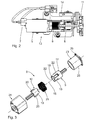
- the drive unit 13 is separate in Fig. 2 illustrated with the drive element 5, the encoder element 7, the gear 6 designed as a planetary gear and the locking element 8. In Fig. 2 on the right the center kinematics 11 is shown.
- Fig. 3 shows an enlarged exploded view of the locking element 8.
- the locking element 8 comprises the locking element drive 9 and the locking element output 10.
- the locking element drive 9 and the locking element output 10 are rotatably connected to each other with respect to a rotation about a drive axis 16.
- the locking element drive 9 has a sleeve portion 17 with parallel to the drive axis 16 extending longitudinal slots 18 which are arranged in an outer cylinder wall of the sleeve portion 17.
- the locking element driven element 10 has a sleeve portion 19 which has an outer diameter such that the sleeve portion 19 of the locking element-driven element 10 in the sleeve portion 17 of the locking element drive 9 at least partially along the drive axis 16 can be arranged.
- the sleeve portion 19 radially with respect to the drive axis of rotation 16 outwardly and on an outer cylindrical surface of the sleeve portion 19 diametrically opposite longitudinal webs 20.
- the longitudinal webs 20 can each in one be arranged corresponding longitudinal slot 18, so that the locking element lock drive 9 and the locking element lock output 10 are rotatably connected to each other.
- a wrap spring element 21 is provided in the area of the sleeve sections 17, 19, a wrap spring element 21 is provided.
- the wrap spring 21 is in Fig. 3 in a relaxed state, so without external force stress represented.
- the wrap spring is designed as a helical spring, wherein the two ends of the wrap spring element 21 bent by about 90 ° and with respect to a cylinder surface formed by the wrap spring 21 radially inwardly, ie the drive axis 16 are facing.
- the inwardly bent ends of the wrap spring element 21 form engagement means 42 and serve to engage in engagement slots 22 on the sleeve portion 17 of the detent element drive 9.
- the movement components of the detent locking element 8, that is to say the detent element drive 9, the detent element output 10 and the coiled spring element 21, coaxial with the two components 9, 10, are arranged in a detent element housing 24, which can be closed by means of a cover drum 23.
- the lid drum 23 has a substantially flat, rectangular lid 25 which serves to close an opening of the latching barrier element housing 24.
- Four holes are provided on the cover 25, so that the cover 25 can be screwed to the locking element housing 24.
- the cylinder portion 26 of the lid drum 23 serves as a brake member. The function of the cover drum 23 will be explained in more detail below.
- the engagement means 42 are each arranged on an end face of the cylinder formed by the wrap spring 21. Along the drive axis of rotation 16, the engagement means 42 are spaced from each other. The engagement means 42 are arranged in mutually spaced, parallel aligned, in particular perpendicular to the drive axis 16 oriented functional planes.
- Fig. 4 and Fig. 6 are in a lid drum 23 facing first functional level according to the section line IV-IV in Fig. 1 created.
- the Fig. 5 and Fig. 7 show a cross section perpendicular to the drive axis of rotation 16 along the section line VV in Fig. 1 as a second functional level.
- the engagement means 42 are arranged in the engagement slots 22 of the locking lock element drive 9 such that a rotational movement of the locking element drive 9 in a clockwise direction (FIG. Fig. 4 ) or counterclockwise ( Fig. 5 ) causes the wrap spring 21 is tensioned. As a result, a predetermined by the wrap spring 21 in an unloaded state inner diameter is reduced. The wrap spring 21 is contracted radially and a torque transmission from the locking element drive 9 on the locking element driven element 10 takes place - regardless of the direction of rotation of the locking element drive 9 - on the longitudinal webs 20 in the longitudinal slots 18th
- An object which is displaced and positioned by means of the device 1 in a certain position, is held securely.
- the locking element 8 guarantees a reliable and secure arrangement of the object.
- the article can be arranged by means of the device 1 continuously, so in any intermediate position.
- the drive unit 13 according to Fig. 8 is essentially identical to the one in Fig. 2 executed drive unit and comprises a designed as an electric motor drive element 5, a planetary gear 6 and a locking element lock 8. With the locking element 8 a kinematic unit in the form of a spur gear 27 is connected. The spur gear as a kinematic unit 27 serves to transmit the drive torque to the transmission element 12.
- the drive unit 13 is arranged in a common drive unit housing 28.
- the transmission element 12 is led out of the housing 28 sealed by means of seals 29.
- the main difference compared to the first embodiment is the design of the locking element 8a, which has clamping rollers 33 instead of a wrap spring element.
- the basic embodiment of the device 1a is in Fig. 9 and shows a view of the carrier element 2 from below in an assembled state.
- the drive unit 13 is fastened to the carrier element 2 by means of the holding plate 14.
- a drive torque is arranged on the in the recesses 3, in Fig. 9 not shown in detail kinematic elements transferred.
- the locking element 8a has an in Fig. 10 shown in the foreground adapter plate 9a, which represents the locking element lock drive.
- the adapter disk 9a is connected by means of two screws 30 with a control disk 31 both rotationally fixed about the drive axis of rotation 16 and axially along the drive axis of rotation 16. It is possible to make the control disk 31 and the adapter disk 9a integral, that is to say in one piece as a single component.
- a release pin 32 is provided, which extends parallel to the drive axis of rotation 16 and on one of the adapter plate 9a facing away from the end face of the control disk 31 is arranged.
- the locking element 8a comprises a cylindrical locking element housing 24a, in which two clamping rollers 33 and a compression spring 34 arranged therebetween are provided.
- the locking element 8a has the locking element output 10a in the form of an output shaft.
- the output shaft 10a is non-rotatably connected by means of a feather key 36 to a clamping hub 35 arranged in the detent element housing 24a with respect to rotation about the drive axis of rotation 16.
- the detent element housing 24a is designed in particular as a stationary housing and comprises a hardened steel ring 40, which is secured in a plastic housing 41 against rotation about the drive axis of rotation 16.
- the clamping hub 35 has an asymmetrical with respect to the drive rotational axis 16, eccentric cross-section.
- the pinch rollers 33 are clamped between the clamping hub 35 and the detent member housing 24a such that rotation of the detent member take-off 10a is blocked.
- the two pinch rollers 33 are biased by the pressure spring 34 arranged therebetween and pressed against the inner wall of the locking element lock housing 24 a on the one hand and against the clamping hub 35 on the other.
- two driving pins 37 are provided, which extend from the clamping hub 35 parallel to the drive axis of rotation 16 and the control disk 31 are facing.
- the driving pins 37 serve to transmit torque between the clamping hub 35 and the control disk 31.
- An axial securing of the control disk 31 to the clamping hub 35 is ensured by a securing ring 38.
- the locking ring 38 is axially mounted on the output shaft 10a.
- a further release pin 32 is provided between one of the pinch rollers 33 and the clamping hub 35.
- Fig. 11 shows the unactuated locking element 8a.
- the clamping hub 35 which is non-rotatably connected by means of the feather key 36 in a rotationally fixed manner to the detent locking element output 10a, bears against an inner wall of the housing 24a at least partially with a circular arc-shaped section. Between the clamping hub 35 and an exposed inner wall of the housing 24a, two pinch rollers 33 are arranged. The two pinch rollers 33 are acted upon by the compression spring 34 with a compressive force and are pressed against the inner wall of the housing 24a.
- the arrangement shown is the latching element 8a in a locked arrangement. It is not possible, in particular not by a rotation of the locking element driven element 10a, to transmit a rotational movement to the locking element drive 9a.
- Fig. 12 the locking element 8a is shown partially cut.
- rotation of the locking element drive 9a along the arrow takes place in a clockwise direction.
- Due to the rotation of the locking element lock drive 9a and the non-rotatably associated control disk 31 is rotated clockwise.
- the in Fig. 12 Trigger pin 32 shown below left a displacement of the adjacent pinch rollers 33 against the spring force of the compression spring 34.
- a corresponding triggered arrangement of the release pin 32 and the corresponding pinch roller 33 is in Fig. 12 drawn dashed. In the triggered arrangement, it is possible that the control disk 31 with respect to the clamping hub 35 can be rotated further.
- the holes 39 in the control disk 31 meet with an inner wall on an outer wall of the driving pins 37.
- the adjacent arrangement of the control disk 31 on the driving pin 37 is also in Fig. 12 shown in dashed lines.
- a direct transmission of a drive torque from the locking element drive 9a via the control disk 31 and the clamping hub 35 on the locking element driven element 10a is possible , As soon as a drive rotational movement of the locking element drive 9a is terminated, the clamping roller 33 can be moved back into a clamping position due to the spring force of the compression spring 34, so that rotation about the drive axis 16 is blocked.
- the locking element 8a allows a latching securing a rotational movement in any position and thus ensures a start any position in a continuous process. Any intermediate positions can be approached and secured by means of the locking element 8a.
- the representation in Fig. 10 shows that the clamping hub 35 itself and the arrangement of the pinch rollers 33 and the release pins 32 are arranged symmetrically to a defined by the screws 30 vertical plane. This makes it clear that a torque transmission to the locking element 8a is independent of a direction of rotation of the drive, in particular the locking element drive 9a, possible.
- the clamping hub 35 has the function of an inclined plane at which the pinch roller 33 is clamped to an inner wall of the latching-lock housing 24a.
- FIG. 13 A third embodiment of the invention described. Structurally identical parts obtained the same reference numerals as in the first embodiment, the description of which is hereby incorporated by reference. Structurally different, but functionally similar parts receive the same reference numerals with a trailing b.
- the device 1b according to the third embodiment substantially corresponds to the first embodiment according to Fig. 1 ,
- the device comprises a drive unit 13 with a central kinematics 11, which connects the drive unit 13 with the transmission element 12.
- the essential difference is that the drive unit 13 has no latching element.
- two locking elements 8b are provided which each have a wrap spring element analogous to the first embodiment.
- the locking elements 8b are adjacent to the recesses 3 and thus arranged between the transmission element 12 and arranged in the respective recess 3, not shown in detail kinematic element.
- the locking elements 8b lock such, emanating from the kinematic elements output-side torque transmission immediately.
- the transmission element 12 is thereby mechanically relieved.
Landscapes
- Engineering & Computer Science (AREA)
- Chemical & Material Sciences (AREA)
- Combustion & Propulsion (AREA)
- Transportation (AREA)
- Mechanical Engineering (AREA)
- Braking Arrangements (AREA)
- Transmission Devices (AREA)
Applications Claiming Priority (1)
| Application Number | Priority Date | Filing Date | Title |
|---|---|---|---|
| DE102012221023.7A DE102012221023A1 (de) | 2012-11-19 | 2012-11-19 | Vorrichtung zur Verlagerung eines Gegenstands und Kraftfahrzeug mit einer derartigen Vorrichtung |
Publications (2)
| Publication Number | Publication Date |
|---|---|
| EP2733054A2 true EP2733054A2 (fr) | 2014-05-21 |
| EP2733054A3 EP2733054A3 (fr) | 2018-07-18 |
Family
ID=49474257
Family Applications (1)
| Application Number | Title | Priority Date | Filing Date |
|---|---|---|---|
| EP13189626.8A Withdrawn EP2733054A3 (fr) | 2012-11-19 | 2013-10-22 | Dispositif pour le déplacement d'un objet et une véhicule automobile, avec un tel dispositif |
Country Status (2)
| Country | Link |
|---|---|
| EP (1) | EP2733054A3 (fr) |
| DE (1) | DE102012221023A1 (fr) |
Cited By (4)
| Publication number | Priority date | Publication date | Assignee | Title |
|---|---|---|---|---|
| CN108463397A (zh) * | 2015-12-09 | 2018-08-28 | 捷豹路虎有限公司 | 机动车辆装置及方法 |
| CN108473166A (zh) * | 2015-12-09 | 2018-08-31 | 捷豹路虎有限公司 | 机动车辆设备及方法 |
| CN110450864A (zh) * | 2019-09-09 | 2019-11-15 | 延锋彼欧汽车外饰系统有限公司 | 一种可移动开启的主动扰流板总成 |
| EP3789276A1 (fr) * | 2019-09-09 | 2021-03-10 | Yanfeng Plastic Omnium Automotive Exterior Systems Co., Ltd. | Ensemble déflecteur actif ouvert mobile |
Families Citing this family (3)
| Publication number | Priority date | Publication date | Assignee | Title |
|---|---|---|---|---|
| DE102018119906B4 (de) * | 2018-08-16 | 2025-11-13 | Dr. Ing. H.C. F. Porsche Aktiengesellschaft | Antriebsanordnung für Kfz-Funktionsteil |
| DE102019108269B4 (de) * | 2019-03-29 | 2023-07-06 | Paragon Gmbh & Co. Kgaa | Luftleitvorrichtung mit Getriebe |
| DE102021103431B4 (de) | 2021-02-15 | 2025-10-23 | Dr. Ing. H.C. F. Porsche Aktiengesellschaft | Stellelement eines Luftleitelementes eines Kraftfahrzeugs |
Citations (2)
| Publication number | Priority date | Publication date | Assignee | Title |
|---|---|---|---|---|
| WO2007095886A1 (fr) | 2006-02-27 | 2007-08-30 | Hs Genion Gmbh | Dispositif de guidage d'air pour un véhicule |
| DE102008029884B4 (de) | 2008-06-24 | 2011-02-03 | Hs Genion Gmbh | System für die Festlegung von Zwischenstellung eines beweglichen Spoilers für ein Kraftfahrzeug |
Family Cites Families (6)
| Publication number | Priority date | Publication date | Assignee | Title |
|---|---|---|---|---|
| DE4305090C2 (de) * | 1993-02-19 | 1995-04-13 | Webasto Karosseriesysteme | Heckspoiler zum Leiten einer Windströmung an Fahrzeugen |
| DE4310879C2 (de) * | 1993-04-02 | 2002-11-14 | Porsche Ag | Kraftfahrzeug, insbesondere Personenkraftwagen |
| DE10354338A1 (de) * | 2003-11-20 | 2005-06-16 | Suspa Holding Gmbh | Freilauf-Brems-Vorrichtung |
| DE102007058648A1 (de) * | 2007-12-04 | 2009-06-10 | Suspa Holding Gmbh | Kardanische Wellenverbindung |
| DE102008024132B4 (de) * | 2008-05-19 | 2010-07-22 | Suspa Holding Gmbh | Spoilerantrieb mit Zwischenstellungen |
| DE102008062150A1 (de) * | 2008-12-16 | 2010-06-24 | Dr. Ing. H.C. F. Porsche Aktiengesellschaft | Verstell-Vorrichtung |
-
2012
- 2012-11-19 DE DE102012221023.7A patent/DE102012221023A1/de not_active Withdrawn
-
2013
- 2013-10-22 EP EP13189626.8A patent/EP2733054A3/fr not_active Withdrawn
Patent Citations (2)
| Publication number | Priority date | Publication date | Assignee | Title |
|---|---|---|---|---|
| WO2007095886A1 (fr) | 2006-02-27 | 2007-08-30 | Hs Genion Gmbh | Dispositif de guidage d'air pour un véhicule |
| DE102008029884B4 (de) | 2008-06-24 | 2011-02-03 | Hs Genion Gmbh | System für die Festlegung von Zwischenstellung eines beweglichen Spoilers für ein Kraftfahrzeug |
Cited By (5)
| Publication number | Priority date | Publication date | Assignee | Title |
|---|---|---|---|---|
| CN108463397A (zh) * | 2015-12-09 | 2018-08-28 | 捷豹路虎有限公司 | 机动车辆装置及方法 |
| CN108473166A (zh) * | 2015-12-09 | 2018-08-31 | 捷豹路虎有限公司 | 机动车辆设备及方法 |
| CN108463397B (zh) * | 2015-12-09 | 2021-03-05 | 捷豹路虎有限公司 | 机动车辆装置及方法 |
| CN110450864A (zh) * | 2019-09-09 | 2019-11-15 | 延锋彼欧汽车外饰系统有限公司 | 一种可移动开启的主动扰流板总成 |
| EP3789276A1 (fr) * | 2019-09-09 | 2021-03-10 | Yanfeng Plastic Omnium Automotive Exterior Systems Co., Ltd. | Ensemble déflecteur actif ouvert mobile |
Also Published As
| Publication number | Publication date |
|---|---|
| DE102012221023A1 (de) | 2014-05-22 |
| EP2733054A3 (fr) | 2018-07-18 |
Similar Documents
| Publication | Publication Date | Title |
|---|---|---|
| EP2733054A2 (fr) | Dispositif pour le déplacement d'un objet et une véhicule automobile, avec un tel dispositif | |
| DE102013103892B4 (de) | Antriebseinheit sowie Mäher und elektrisch betriebene Strebe mit einer solchen Antriebseinheit | |
| EP3844046B1 (fr) | Colonne de direction steer-by-wire à réglage électrique et véhicule automobile | |
| EP3232076A1 (fr) | Module comprenant un dispositif de friction | |
| DE102017201594B4 (de) | Motorisch verstellbare Lenksäule für ein Kraftfahrzeug | |
| DE102013213708A1 (de) | Schneckengetriebe für eine Lenkhilfevorrichtung eines Kraftfahrzeuges mit Spielausgleich | |
| EP3870495B1 (fr) | Colonne de direction pour un véhicule automobile | |
| DE102011050440B3 (de) | Selbsttätig schaltende Kupplung für eine Kraftfahrzeug-Außenspiegelverstellung | |
| DE102017200888A1 (de) | Elektrisch verstellbare Lenksäule für ein Kraftfahrzeug | |
| EP4182190B1 (fr) | Enrouleur de ceinture de sécurité | |
| EP3477154A1 (fr) | Dispositif de serrage | |
| DE102020212481A1 (de) | Lenksäule für ein Kraftfahrzeug | |
| DE102023115292A1 (de) | Aktor zur Bereitstellung eines Drehmoments mit einem Linearantrieb | |
| EP1032522B1 (fr) | Mecanisme de commande a moteur electrique pour systeme de direction de vehicule | |
| EP3190254B1 (fr) | Entraînement de cisaille | |
| DE102008024132B4 (de) | Spoilerantrieb mit Zwischenstellungen | |
| DE102008061606B4 (de) | Bremsvorrichtung und Motor mit Geschwindigkeitsreduzierungsmechanismus | |
| EP3622198B1 (fr) | Système modulaire pour la réalisation d'un dispositif d'actionnement | |
| EP4177132B1 (fr) | Entraînement de réglage pour une colonne de direction réglable par moteur et colonne de direction pour un véhicule automobile | |
| EP4614030A2 (fr) | Module de frein de stationnement | |
| EP2037067B1 (fr) | Dispositif d'entraînement pour une porte de véhicule | |
| DE202008009704U1 (de) | Vorrichtung zum Verstellen eines Spoilerblatts für ein Kraftfahrzeug, insbesondere zum Verstellen eines Luftbremsschildes | |
| DE202021102062U1 (de) | Aktivierbare Antriebsvorrichtung | |
| EP1879758B1 (fr) | Stabilisateur electromecanique en plusieurs parties de vehicule automobile dote d'un dispositif de blocage et procede antiroulis en cas de defaillance ou de mise hors circuit du stabilisateur actif | |
| EP3523160B1 (fr) | Agencement de transmission pour mécanisme d'entraînement de broche, entraînement de broche et siège de véhicule |
Legal Events
| Date | Code | Title | Description |
|---|---|---|---|
| PUAI | Public reference made under article 153(3) epc to a published international application that has entered the european phase |
Free format text: ORIGINAL CODE: 0009012 |
|
| 17P | Request for examination filed |
Effective date: 20131022 |
|
| AK | Designated contracting states |
Kind code of ref document: A2 Designated state(s): AL AT BE BG CH CY CZ DE DK EE ES FI FR GB GR HR HU IE IS IT LI LT LU LV MC MK MT NL NO PL PT RO RS SE SI SK SM TR |
|
| AX | Request for extension of the european patent |
Extension state: BA ME |
|
| PUAL | Search report despatched |
Free format text: ORIGINAL CODE: 0009013 |
|
| AK | Designated contracting states |
Kind code of ref document: A3 Designated state(s): AL AT BE BG CH CY CZ DE DK EE ES FI FR GB GR HR HU IE IS IT LI LT LU LV MC MK MT NL NO PL PT RO RS SE SI SK SM TR |
|
| AX | Request for extension of the european patent |
Extension state: BA ME |
|
| RIC1 | Information provided on ipc code assigned before grant |
Ipc: B62D 35/00 20060101AFI20180611BHEP |
|
| STAA | Information on the status of an ep patent application or granted ep patent |
Free format text: STATUS: THE APPLICATION IS DEEMED TO BE WITHDRAWN |
|
| 18D | Application deemed to be withdrawn |
Effective date: 20190119 |