EP2733074A2 - Vorrichtung zur Kraftstoffspeicherung, Luftfahrzeug und Verfahren - Google Patents
Vorrichtung zur Kraftstoffspeicherung, Luftfahrzeug und Verfahren Download PDFInfo
- Publication number
- EP2733074A2 EP2733074A2 EP13005017.2A EP13005017A EP2733074A2 EP 2733074 A2 EP2733074 A2 EP 2733074A2 EP 13005017 A EP13005017 A EP 13005017A EP 2733074 A2 EP2733074 A2 EP 2733074A2
- Authority
- EP
- European Patent Office
- Prior art keywords
- fuel
- tank
- volume
- filling
- storage device
- Prior art date
- Legal status (The legal status is an assumption and is not a legal conclusion. Google has not performed a legal analysis and makes no representation as to the accuracy of the status listed.)
- Granted
Links
Images

Classifications
-
- B—PERFORMING OPERATIONS; TRANSPORTING
- B64—AIRCRAFT; AVIATION; COSMONAUTICS
- B64D—EQUIPMENT FOR FITTING IN OR TO AIRCRAFT; FLIGHT SUITS; PARACHUTES; ARRANGEMENT OR MOUNTING OF POWER PLANTS OR PROPULSION TRANSMISSIONS IN AIRCRAFT
- B64D37/00—Arrangements in connection with fuel supply for power plant
- B64D37/02—Tanks
- B64D37/06—Constructional adaptations thereof
-
- B—PERFORMING OPERATIONS; TRANSPORTING
- B64—AIRCRAFT; AVIATION; COSMONAUTICS
- B64D—EQUIPMENT FOR FITTING IN OR TO AIRCRAFT; FLIGHT SUITS; PARACHUTES; ARRANGEMENT OR MOUNTING OF POWER PLANTS OR PROPULSION TRANSMISSIONS IN AIRCRAFT
- B64D37/00—Arrangements in connection with fuel supply for power plant
- B64D37/02—Tanks
- B64D37/14—Filling or emptying
- B64D37/16—Filling systems
-
- B—PERFORMING OPERATIONS; TRANSPORTING
- B64—AIRCRAFT; AVIATION; COSMONAUTICS
- B64D—EQUIPMENT FOR FITTING IN OR TO AIRCRAFT; FLIGHT SUITS; PARACHUTES; ARRANGEMENT OR MOUNTING OF POWER PLANTS OR PROPULSION TRANSMISSIONS IN AIRCRAFT
- B64D37/00—Arrangements in connection with fuel supply for power plant
- B64D37/02—Tanks
- B64D37/14—Filling or emptying
- B64D37/20—Emptying systems
-
- B—PERFORMING OPERATIONS; TRANSPORTING
- B64—AIRCRAFT; AVIATION; COSMONAUTICS
- B64D—EQUIPMENT FOR FITTING IN OR TO AIRCRAFT; FLIGHT SUITS; PARACHUTES; ARRANGEMENT OR MOUNTING OF POWER PLANTS OR PROPULSION TRANSMISSIONS IN AIRCRAFT
- B64D37/00—Arrangements in connection with fuel supply for power plant
- B64D37/02—Tanks
- B64D37/14—Filling or emptying
- B64D37/20—Emptying systems
- B64D37/24—Emptying systems using gas pressure
-
- G—PHYSICS
- G01—MEASURING; TESTING
- G01F—MEASURING VOLUME, VOLUME FLOW, MASS FLOW OR LIQUID LEVEL; METERING BY VOLUME
- G01F23/00—Indicating or measuring liquid level or level of fluent solid material, e.g. indicating in terms of volume or indicating by means of an alarm
- G01F23/80—Arrangements for signal processing
- G01F23/802—Particular electronic circuits for digital processing equipment
-
- B—PERFORMING OPERATIONS; TRANSPORTING
- B64—AIRCRAFT; AVIATION; COSMONAUTICS
- B64C—AEROPLANES; HELICOPTERS
- B64C27/00—Rotorcraft; Rotors peculiar thereto
- B64C27/04—Helicopters
Definitions
- the present invention relates to a fuel storage device provided with a reservoir, an aircraft provided with such a reservoir and a method for controlling such a reservoir.
- the invention relates to an aircraft and in particular an aircraft comprising a rotary wing.
- a rotary wing aircraft has specific characteristics that lead to significant differences with an airplane or an automobile.
- a fuel storage device usually comprises at least one tank containing the fuel.
- the storage device usually includes an expansion volume.
- Such an expansion volume serves to accommodate a portion of the fuel stored in the tanks in case of expansion of this fuel.
- the expansion volume then avoids the creation of significant tensions in the walls of the tanks, and / or the overflow of fuel by a venting system for example.
- Aircraft certification regulations may impose a minimum volume on this expansion volume.
- paragraph 969 of the certification regulation known as "CS 29" specifies that the expansion volume must be greater than or equal to two percent of the total volume of the tanks.
- normal position or "normal condition” means the authorized positions of the vehicle by the builder when filling. These authorized positions can be defined for example through a roll angle and a threshold pitch angle of the vehicle.
- a fuel storage device generally includes a venting circuit for discharging into the atmosphere a portion of the gas contained in the storage device.
- the filling orifice must be positioned carefully so that the upper part of the tank is not filled when filling the tank. This upper part must then be in line with a filling plane passing through the filling orifice.
- This first solution has the advantage of being simple.
- the constraint related to the positioning of the filling orifice can make its integration complicated on certain aircraft, in particular aircraft having tanks arranged within a "barque" arranged under a cabin floor.
- an expansion vessel is used which defines the required expansion volume.
- This expansion vessel is distinct from the tank with which it is in communication. Therefore, the expansion tank can be offset relative to this reservoir, for example in an upper part of a venting circuit.
- this second solution sometimes induces the arrangement of ancillary safety means to prevent a risk of fire in case of crash, possibly maximized by the presence of dilated fuel in a remote expansion tank.
- This auxiliary device is obtained by means of a pipe running from the upper part of the tank and going towards a container containing activated carbon.
- This container contains activated carbon to clean up the gases escaping from the fuel tank before they are released into the atmosphere
- the system comprises an expansion tank arranged between the fuel tank and said container.
- the automobile is generally provided with devices shutting off the venting circuit when the filling plug and / or the filling filler provided in the vehicle body are open.
- Rotary wing aircraft and especially helicopters are not conventionally equipped with a gas filtering container.
- the fuel tank is directly connected to the open air by pipes, or even by at least one anti-overturning valve, the function of which is to avoid emptying the fuel tank through the setting circuit. in the open air in case of reversal of the aircraft.
- the fuel tanks are generally arranged in the wings.
- the architectural problem related to an aircraft is therefore completely different from the problem associated with a helicopter type rotary wing aircraft for example.
- refueling is usually done by a hatch arranged on the top wall of the fuel tank.
- the wing usually having a slope, part of the tanks remains empty after refueling and thus represents the required expansion volume.
- this fuel can flow into the ventilation chamber. Transfer pumps then return the fuel from the ventilation chamber to the tanks.
- the tanks are under pressure.
- the fuel storage device has a complexity and dimensioning that does not seem compatible with the requirements of rotary wing helicopter type aircraft in particular.
- DE19925728 which has an expansion vessel arranged in series on a venting circuit.
- the expansion vessel is further disposed within a reservoir.
- the expansion volume delimited by the expansion vessel communicates on the one hand with the inside of the tank via an assembly comprising at least one first valve, and, on the other hand, with the outside by a second valve and an activated carbon treatment system.
- the fuel can move from the tank to the expansion tank and vice versa
- the document EP0233681 has a fuel storage device comprising a tank and an expansion tank arranged in this tank.
- the document US 2005/199294 has a tank connected to a filler pipe leading to an orifice of filling.
- a vent line connects the tank to the open air.
- an expansion vessel is arranged outside the reservoir, this expansion vessel being connected by a high hose and a low hose to said vent line.
- the filling orifice is further present in a plane directly above said hoses.
- the document US 2002/121300 has a reservoir connected to a filler pipe opening on a filling port.
- an expansion tank is arranged in the tank.
- a pipe then extends from said expansion tank to a steam treatment system.
- the document DE 37 19 834 presents a reservoir.
- an expansion tank is arranged in the tank.
- a pipe then extends from said expansion tank to the outside.
- the document is also known DE 41 21 321 .
- the expansion vessel comprises a wall made from a foam comprising open cells, the expansion tank filling with fuel slower than the tank.
- this storage device does not appear to be compatible with certification regulations specifying that the expansion volume should not be inadvertently filled when the aircraft is in a normal ground position.
- a fuel volume may not reach the supply line. This volume of fuel is sometimes referred to as “non-consumable volume” in the measure where this volume of fuel can not be consumed by an engine.
- the manufacturers introduce sloping surfaces in the bottom of the tanks to direct the fuel towards the supply line. Such surfaces are called “slope" for simplification.
- the slopes can be directed along the longitudinal and transverse directions of the vehicle.
- the tanks can be made of a flexible material.
- a flexible material comprises for example a polyester support and a mixture of elastomers. Foams inserted in the compartment of a reservoir thus make it possible to make slopes on which a flexible reservoir rests.
- the added foams have a significant mass.
- the document FR2294913 discloses an expansible means of fuel storage that can be expanded and come to a position in which it is at least partially outside an area of a so-called "surface area” aircraft.
- a fuel storage device represents a complex system, difficult to optimize. Indeed, the consumable volume stored can be minimized by an expansion volume and the introduction of slopes.
- the document EP2135805 has an open tank on the outside. A further is arranged in this tank, the volume of the besides depending on the pressure prevailing outside this tank.
- the document US 2657884 describes a reservoir provided with inflatable members disposed between stiffeners. These inflatable bodies are intended to evacuate a fluid stuck between the stiffeners.
- US 2736356 discloses a fuel tank separated from a pressurizing means by a movable membrane.
- the present invention therefore relates to an innovative storage device that can meet the requirements for an expansion volume.
- a fuel storage device is provided with at least one reservoir, this reservoir having an envelope extending in elevation from a bottom to an upper wall.
- This storage device is provided with at least one inflatable bag arranged in said casing, said storage device comprising an inflating / deflating means inflating each inflatable bag at least partially in order to reach a volume inflated prior to a filling of the reservoir and deflating said inflatable bag after filling to ensure the presence of an expansion volume in said tank.
- the inflated volume is then at least equal to the expansion volume to be guaranteed for the storage device.
- This storage device therefore includes an expansion device for providing an expansion volume, this expansion device being provided with at least one inflatable bag and an inflation / deflation means.
- the air bag is inflated prior to filling.
- the space filled by the airbag in the envelope is not occupied by a liquid during filling.
- each airbag is deflated by means of an autopiloted command or sent by a crew.
- the storage device is then provided with an expansion volume at least equal to the inflated volume of the bags prior to filling.
- the air bag can be deflated on the ground and therefore before the flight, and possibly immediately after filling.
- the expansion volume can not be filled by mistake during refueling.
- Each bag does not communicate with the tank, and releases once deflated an expansion volume.
- the expansion volume is actually present in the tank.
- the invention therefore has a device without a vase expansion. This device can also be effective regardless of the location of the fuel filling port.
- the invention therefore proposes a simple system to guarantee the presence of an expansion volume within the tanks meeting the requirements of the certification regulations.
- the crew of the aircraft may decide not to use the expansion volume to fill the fuel tank to its maximum volume (in the case of application not requiring an expansion volume).
- This storage device may further comprise one or more of the following features.
- Each bag is for example provided with a strong and waterproof envelope.
- At least one bag is attached to the upper wall of the tank.
- the airbag is then inflated and deflated only to provide an expansion volume.
- each bag can possibly fulfill not one, but two functions fundamental. Indeed, each bag allows to provide an expansion volume and direct the fuel to a feeding area. The useful volume of the tank is therefore very well exploited.
- At least one bag is attached to said bottom to, on the one hand, provide an expansion volume and, on the other hand, to provide at least one variable inclination slope in order to direct the fuel towards a predetermined area of the tank by gravity.
- this combination creates a completely secure expansion volume and increases the capacity of the fuel tanks. Moreover, this combination can be integrated into an already existing system.
- this combination makes it easy to manage the distribution of masses in the device.
- the crew may decide to cancel, for example, the expansion volumes in the central tanks (close to the center of gravity of the apparatus) in order to accumulate them in a tank eccentric.
- the predetermined zone may then be the reservoir supply zone, ie the zone of the reservoir receiving an inlet section of a fuel transfer line to a motor.
- the transfer line is equipped with a transfer pump, the slopes can direct fuel to this transfer pump.
- Each airbag can rest on the bottom of the tank by being fixed reversibly or irreversibly.
- the variable slope formed by a bag is then a surface of the bag directed towards the feed zone of the bottom of the tank.
- the invention has a reservoir provided with a variable gradient bottom on command of an inflation / deflation means.
- Each slope may vary between a minimum position, corresponding to a zero or almost zero slope, to a maximum position corresponding to a maximum slope defined by the manufacturer.
- the inflating / deflating means increases the inclination of a slope formed at the bottom of the tank. Conversely, by deflating an air bag, the inflation / deflation means reduces the inclination of a slope formed at the bottom of the tank.
- the invention does not provide a reservoir having a fixed slope made using foams, or an expandable tank conforming to the shape of its container and / or adapting to the onboard fuel volume.
- At least one tank has at least one variable slope made using an air bag and an inflation / deflation means.
- Such a tank thus has a bottom having at least one movable slope depending on the amount of fuel present in the tank.
- the airbags are at least partially inflated.
- the tank can then accommodate a maximized fuel volume ensuring however the presence of an expansion volume after filling.
- the device may contain a signaling means for signaling the end of a filling.
- a signaling means is for example provided with a level sensor, a warning means, and / or a manual signaling means.
- the partial inflation of the bags before filling is not intended to provide slopes precisely directing the fuel to a feeding area, but allows to reserve a volume of expansion in the tank.
- the inflating / deflating means can inflate the airbags, partially or totally. This operation can be carried out insofar as the volume of fuel contained has decreased. Thus, the presence of an inflated bag does not affect the minimum expansion volume present in the tank.
- the tank then has slopes at its bottom to further minimize the volume of non-consumable fuel.
- This storage device thus makes it possible to optimize the volume of consumable fuel while guaranteeing a volume of expansion without departing from the general inventive concept.
- Each bag is also possibly compartmentalized to present a first compartment to inflate / deflate to obtain an expansion volume, and a second compartment to provide a slope. Each step is then carried out with precision.
- the storage device may comprise means for measuring the volume of fuel connected to the inflation means to automatically adjust said inclination according to said volume.
- the inflation / deflation means inflates at least one bag depending on the amount of fuel present in the tank.
- This measuring means may be a gauging system, or a sensor placed at a height defined by the manufacturer to detect the presence of fuel at this height.
- the inflation / deflation means optionally inflates at least one inflatable bag below a fuel threshold to provide adequate slopes.
- the storage device comprises a system for measuring a flight duration.
- the manufacturer may set a flight time from which the airbags must be fully deployed.
- the storage device comprises a manual control means for controlling the inflating / deflating means.
- the crew can then choose the time required to inflate the airbags.
- the crew may optionally adjust the degree of inclination of the slopes by adjusting the pressure of the inflation fluid contained in each air bag.
- the crew can adjust said inclination to better adapt to the type of mission to achieve.
- the storage device may comprise a pressure sensor. This pressure sensor makes it possible to provide information relating to the slope formed by an airbag.
- the storage device is for example provided with a display means for displaying information relating to said slope.
- This display means can therefore cooperate with a pressure sensor to determine whether an inflatable bag is inflated or deflated.
- the storage device is also for example provided with an alert means for alerting an individual of the actual swelling of the bags.
- the device is equipped with a gauging system measuring the height of fuel in the tank, the gauging system has a measurement law for each slope inclination, each tonnage law providing the fuel volume according to said height.
- totalnage law for each inclination is the use of a plurality of laws, or the use of a single law having at least one variable parameter depending on the state of the air bags.
- Such a gauging system may include a gauging rod and a processing unit.
- the processing unit then communicates with a dedicated means for determining the state of the air bags, such as a pressure sensor for example.
- the storage device may also comprise a reversible attachment means of each inflatable bag to a reservoir.
- the invention also relates to an aircraft provided with such a storage device.
- the invention relates to a fuel storage method using the storage device.
- At least partially at least one inflatable bag is inflated to provide an expansion volume in the tank before filling the tank, then deflated each inflatable bag after filling.
- This method may include one or more of the following features.
- each inflatable bag can be inflated when the fuel volume is below a predetermined threshold after filling to provide a slope at the bottom of a tank for directing the fuel contained by gravity to a predetermined zone of the reservoir depending on the level. fuel.
- the inflatable bags are inflated only below a fuel threshold.
- inflatable bags can be inflated after filling. In this configuration, the deflation of the bags after filling can be inhibited.
- the inflatable bags are inflated when said quantity becomes lower than said threshold.
- An automatic procedure can therefore be implemented to manage the slopes present at the bottom of the tank.
- a crew may also require inflating the bags manually in an alternative or complementary manner.
- At least one gauging law being determined to provide a volume of fuel as a function of a fuel height in the tank, said gauging law can be modified when said slope is modified.
- This modification can be obtained by the use of several gauging laws, or by modifying at least one parameter of a gauging law.
- the storage device when the storage device is implemented on an aircraft provided with at least one motor, it is possible to deflate each airbag when said engine is stopped.
- Manual inhibiting means may optionally be provided to prevent such deflation on order of a crew.
- step d) can be inhibited if step e) is to be implemented.
- each air bag after the filling on the ground, and in particular before a displacement of the aircraft to ensure the presence of the volume of expansion on the ground.
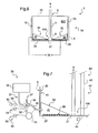
- the figure 1 presents a vehicle 1 according to a first embodiment of the invention.
- This vehicle is for example an aircraft, such as an aircraft equipped with a rotary wing.
- This aircraft 1 has a storage device 10.
- This storage device 10 may in particular be a system for storing the fuel supplying a power plant 9.
- the other organs of the aircraft are not represented so as not to weigh down the figure 1 .
- the storage device is provided with at least one reservoir 15 arranged in a compartment 5 of the vehicle 1.
- the reservoir 15 is then provided with an envelope 20 delimiting a storage space.
- This envelope 20 thus extends in elevation from a bottom 21 to an upper wall 22 which are separated by lateral walls 23.
- the storage device 10 includes a fuel transfer pipe 6 opening onto a predetermined fuel transfer zone 100 of the reservoir 15.
- This pipe 6 may comprise either at least one fuel transfer pipe 7, or according to the example shown at least one fuel transfer pipe 7 and a booster pump 8.
- the storage device may also include a venting system 300 and a fill system 200, such as a gravity fill system.
- This storage device then comprises a system for providing an expansion volume in the reservoir 15.
- This storage device 10 is provided with at least one inflatable bag 25 arranged in the envelope 20.
- inflating / deflating means 35 is connected to each bag 25 for inflating each inflatable bag 25 according to a predetermined method.
- This inflating / deflating means 35 may include a pressure generator 36 communicating with at least one inflatable bag 25 by a flexible tubing and a valve 38.
- the inflating / deflating means 35 is manually activatable, or automatically via a control unit applying a procedure defined by the constructor.
- Any reversible inflation / deflation system of a bag can be used.
- the device is optionally equipped with an alert means signaling the state of each bag to a crew.
- the inflating / deflating means at least partially inflates each bag to reach a volume inflated prior to filling the reservoir, and deflates said bag. inflatable after filling to ensure the presence of an expansion volume in said tank.
- each inflatable bag is fixed in the reservoir to the upper wall 22 of the casing, possibly by reversible means.
- each inflatable bag is completely inflated by the inflating / deflating means 35.
- the level of fuel in the tank increases and can "drown" the airbag according to the representation of the figure 4 .
- each inflatable bag is deflated by the inflating / deflating means 35.
- the storage device comprises a system for providing an expansion volume and variable slopes at the bottom 21 of at least one tank, and in particular at the bottom of a tank including a predetermined zone 100 of fuel transfer.
- This storage device 10 then comprises at least one inflatable bag 25 that can be inflated on request, in particular to provide a slope 30 at the bottom of a tank. This slope 30 thus allows a fuel contained in the tank to be directed by gravity towards the predetermined zone 100.
- the storage device 10 is provided with inflating / deflating means 35 for inflating / deflating inflatable bags 25 of at least one reservoir.
- inflating / deflating means 35 adjusts the inclination of the slope generated by the inflatable bag between a minimum position and a maximum position and generates an expansion volume.
- each inflatable bag may be disposed within the shell 20 of a reservoir.
- Each inflatable bag is optionally attached to this envelope by a reversible fastening means 26.
- a reversible attachment means comprises for example a self-gripping strip using a layer provided with hooks and a layer provided with loops.
- an airbag opposed to the generated slope 30 is attached to the tank shell.
- the airbag can then be fixed on the bottom 21 of the envelope.
- each inflatable bag is fixed irreversibly to the envelope.
- inflation / deflation means 35 may comprise at least one pressure generator 36.
- a pressure generator 36 then communicates with at least one inflatable bag 25 by at least one flexible pipe and a valve 38.
- a first pipe 37 connects a valve 38 to the pressure generator, and a second pipe 39 connects the valve to an air bag.
- the valve may have three positions so as to be connected to a fluid discharge line 37 'to deflate an airbag.
- the fluid discharge pipe 37 ' may be directed to a pressure generator.
- a single pressure generator can be used to inflate / deflate several air bags, or all air bags for example.
- Any device for conveying fluid from a pressure generator to an airbag can be furthermore envisaged.
- each inflatable bag may comprise two independent compartments.
- the inflation / deflation means is then connected to each compartment.
- This inflation / deflation means for example cooperates with a first compartment to generate an expansion volume in the tank, and with the second compartment to provide a slope in the tank.
- the inflating / deflating means inflates or deflates the airbags depending on the phase of flight and the amount of fuel present in the reservoir.
- the invention proposes to inflate the airbags in predefined situations to both allow the creation of an expansion volume and to provide slopes for directing the fuel to a predetermined area.
- the storage device is then provided with a means for measuring the volume of fuel 40 contained in the reservoir, and / or a measurement system 45 of a flight duration, and / or a manual control means 50 of said inflation / deflation means 35.
- a means 40 for measuring the volume of fuel is connected to the inflation / deflation means 35 to automatically adjust the inclination of the slopes of the tank according to the volume of fuel present in the tank.
- This measuring means 40 may include a sensor 41 changing state when the fuel height in the tank passes a threshold.
- This sensor 41 may be connected to each valve 38 of an inflation / deflation means 35, or to a processing means analyzing the state of the sensor to control each valve 38 if appropriate.
- the measuring means 40 optionally includes a gauging system 42.
- This gauging system 42 optionally comprises a gauging rod 43 cooperating with a processing unit 44.
- the gauging rod 43 measures for example the height of fuel in the tank.
- the processing unit 44 deduces the volume of fuel contained from at least one gauging law converting the fuel height to the volume of fuel.
- This processing unit communicates with each valve 38 of an inflation / deflation means 35, or with a processing means analyzing the information from the processing unit to control each valve 38 if necessary.
- the storage device is provided with a measurement system 45 of a flight duration.
- the manufacturer can determine a flight time to ensure that the reduced internal space following inflating air bags in flight is sufficient to contain the stored fuel.
- the measuring system 45 then cooperates with the inflation / deflation means 35, possibly via a treatment system 46.
- the storage device includes a manual control means 50 of the inflating / deflating means 35, for example connected to each valve 38.
- This valve may be provided with a position indicator 38 '.
- the storage device may comprise at least one pressure sensor 55 for estimating the pressure of the fluid contained in an air bag.
- the pressure sensor can cooperate with a pipe 39 of the inflating / deflating means 35.
- This sensor makes it possible to deliver information representative of the state of at least one inflatable bag, and hence representative of the inclination of the slope generated by this inflatable bag.
- a low pressure indicates that an airbag is deflated while significant pressure indicates that an air bag is inflated.
- This pressure sensor may be associated with a display means 60 displaying information relating to said slope and / or an alert means 65 alerting an individual that said bag is inflated, via a visual or audible alarm.
- the display means and the warning means can be arranged in the same equipment.
- the storage device 10 when the storage device 10 is provided with a gauging system 42 measuring the height of fuel in the tank 15, the gauging system 42 may include a gauging law for each permitted inclination of the slopes of the tank.
- the storage device may for example apply a gauging law when the air bags are deflated, and a gauging law when the inflatable bags are inflated.
- the airbags are at least partially inflated.
- Information may be transmitted to the crew to signal at least partial inflation of the bags.
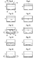
- the tank can be filled with fuel, the filling being shown schematically by the arrow F.
- the fuel level in the tank can reach a level P0. Therefore, the bags 25 are deflated to lower the fuel level to a level P1.
- the tank then has an expansion volume corresponding at least to the volume of the bags before the start of filling.
- the fuel free surface can then either reach a threshold Q fixed by the manufacturer, or remain below this threshold Q.
- This threshold is defined by the manufacturer to ensure the presence of an expansion volume when the bags are inflated.
- the fuel consumption by the engines of an aircraft for example induces a drop in the fuel level in the tank according to the arrow F1.
- the inflating air bags are triggered.
- the figure 12 illustrates inflating the air bags.
- Each inflatable bag then defines a slope inclined towards a predetermined zone 100.
- Each slope thus has an inclination ⁇ with respect to the lower wall of the tank shell.
- the gauging law applied by a gauging system is then favorably modified.
- the figure 13 has a tank with fully inflated airbags.
- the airbags are deflated after the flight and on the ground, at the request of a crew, or when the engines stop for example.
- the figure 17 then presents the condition of the airbags following this deflation.
- the Figures 14 and 15 illustrate the process in the presence of partial filling. These Figures 14 and 15 may also apply to an intermediate phase of flight.
- the threshold Q may for example represent a height of fuel in the tank, a volume of fuel or a flight duration.
- the first embodiment and the second embodiment are, for example, combinable.
Landscapes
- Engineering & Computer Science (AREA)
- Aviation & Aerospace Engineering (AREA)
- Signal Processing (AREA)
- Physics & Mathematics (AREA)
- Fluid Mechanics (AREA)
- General Physics & Mathematics (AREA)
- Cooling, Air Intake And Gas Exhaust, And Fuel Tank Arrangements In Propulsion Units (AREA)
Applications Claiming Priority (1)
| Application Number | Priority Date | Filing Date | Title |
|---|---|---|---|
| FR1203101A FR2998268B1 (fr) | 2012-11-19 | 2012-11-19 | Dispositif de stockage de carburant, aeronef et procede |
Publications (3)
| Publication Number | Publication Date |
|---|---|
| EP2733074A2 true EP2733074A2 (de) | 2014-05-21 |
| EP2733074A3 EP2733074A3 (de) | 2015-07-22 |
| EP2733074B1 EP2733074B1 (de) | 2017-03-15 |
Family
ID=47594843
Family Applications (1)
| Application Number | Title | Priority Date | Filing Date |
|---|---|---|---|
| EP13005017.2A Active EP2733074B1 (de) | 2012-11-19 | 2013-10-21 | Vorrichtung zur Kraftstoffspeicherung, Luftfahrzeug und Verfahren |
Country Status (5)
| Country | Link |
|---|---|
| US (1) | US9623980B2 (de) |
| EP (1) | EP2733074B1 (de) |
| CN (1) | CN103818559B (de) |
| CA (1) | CA2830709C (de) |
| FR (1) | FR2998268B1 (de) |
Families Citing this family (13)
| Publication number | Priority date | Publication date | Assignee | Title |
|---|---|---|---|---|
| FR3003543B1 (fr) * | 2013-03-22 | 2015-12-25 | Eurocopter France | Reservoir muni d'un clapet de surpression |
| CN106697293B (zh) * | 2017-02-16 | 2023-06-06 | 千叶智能科技(深圳)有限公司 | 涵道式垂直升降飞行器及其液体容器装置 |
| CN106945842A (zh) * | 2017-03-23 | 2017-07-14 | 中国商用飞机有限责任公司北京民用飞机技术研究中心 | 一种负压式低死油防气泡飞机油箱装置 |
| CA3076391A1 (en) * | 2017-09-29 | 2019-04-04 | Bombardier Inc. | Method, system, and graphical indicator for providing a lateral center of gravity of an aircraft |
| CN107719114A (zh) * | 2017-10-30 | 2018-02-23 | 北京汽车研究总院有限公司 | 一种供油设备及车辆 |
| US10731639B2 (en) * | 2018-07-09 | 2020-08-04 | Lockheed Martin Corporation | Variable geometry fuel sump pads |
| CN109018360B (zh) * | 2018-08-17 | 2023-12-15 | 成都农业科技职业学院 | 一种基于rtk的精量无人机直播器的使用方法 |
| NO345292B1 (en) * | 2019-01-25 | 2020-11-30 | Environgas As | An apparatus and a method for controlling a pulling of an inflatable bladder through an aperture |
| CN110466786B (zh) * | 2019-08-20 | 2021-08-31 | 杭州闻典通讯技术有限公司 | 一种机载保压油箱 |
| KR102079078B1 (ko) * | 2019-09-23 | 2020-02-19 | 국방과학연구소 | 비행체 연료공급 시스템 |
| CN115027836B (zh) * | 2022-05-07 | 2025-07-11 | 湖北同威专用汽车有限公司 | 一种危化品运输罐 |
| BE1030693B1 (fr) * | 2022-07-07 | 2024-02-05 | Plastic Omnium Advanced Innovation & Res | Système de stockage de carburant de véhicule comprenant une vessie |
| CN117163300B (zh) * | 2023-09-21 | 2026-04-14 | 中国航空工业集团公司沈阳飞机设计研究所 | 一种基于主动重心控制的空中加油调节方法及系统 |
Citations (14)
| Publication number | Priority date | Publication date | Assignee | Title |
|---|---|---|---|---|
| US2657884A (en) | 1950-11-09 | 1953-11-03 | Wingfoot Corp | Fuel cell |
| US2736356A (en) | 1954-10-18 | 1956-02-28 | Chance Vought Aircraft Inc | Expellant bladder type fuel cell |
| US3409253A (en) | 1966-12-02 | 1968-11-05 | Whittaker Corp | Retractable fuel tank for aircraft |
| FR2294913A1 (fr) | 1974-12-19 | 1976-07-16 | British Aircraft Corp Ltd | Avion comprenant un moyen expansible de stockage de carburant |
| EP0233681A2 (de) | 1986-01-14 | 1987-08-26 | Jaguar Cars Limited | Kraftstofftank |
| DE3719834A1 (de) | 1986-09-18 | 1988-03-24 | Daimler Benz Ag | Entlueftungseinrichtung fuer kraftstofftanks von kraftfahrzeugen |
| DE4121321A1 (de) | 1991-06-27 | 1993-01-07 | Bayerische Motoren Werke Ag | Kraftstoffbehaelter fuer ein kraftfahrzeug |
| US5927651A (en) | 1997-05-15 | 1999-07-27 | Mcdonnell Douglas | Expandable fuel cell |
| US6021978A (en) | 1998-04-04 | 2000-02-08 | Goss; Clinton Gilbert | Anti-explosion protection system for flammable vapors |
| DE19925728A1 (de) | 1999-06-07 | 2000-12-21 | Benteler Werke Ag | Kraftstoffversorgungsanlage |
| US20020121300A1 (en) | 2001-03-01 | 2002-09-05 | Moshe Ehrman | Liquid fuel trap |
| US20050199294A1 (en) | 2004-03-12 | 2005-09-15 | Vaitses Stephen P. | System and method for tank pressure compensation |
| US7621483B2 (en) | 2004-04-29 | 2009-11-24 | Airbus Uk Limited | Aircraft and fuel venting system therefor |
| EP2135805A2 (de) | 2008-06-19 | 2009-12-23 | Honeywell International Inc. | Auf Umgebungsdruck reagierender Kraftstofftank mit variablem Volumen |
Family Cites Families (4)
| Publication number | Priority date | Publication date | Assignee | Title |
|---|---|---|---|---|
| US2654553A (en) * | 1949-09-20 | 1953-10-06 | Thompson Prod Inc | Fuel tank |
| HUP9800578A1 (hu) | 1998-03-16 | 1999-11-29 | István Szakály | Eljárás és berendezés tartályokban tárolt illékony anyagok töltési és légzési veszteségeinek kiküszöbölésére, továbbá a tárolt termék és a tartályok korrózió elleni védelmére |
| GB2434416A (en) | 2006-01-19 | 2007-07-25 | Carlo B Chiarella | A container for a combustible substance |
| NL1039103C2 (nl) | 2011-10-12 | 2013-04-23 | Erik Jeroen Eenkhoorn | Element voor het elimineren van turbulent gedrag van vloeistof in een houder. |
-
2012
- 2012-11-19 FR FR1203101A patent/FR2998268B1/fr active Active
-
2013
- 2013-10-21 EP EP13005017.2A patent/EP2733074B1/de active Active
- 2013-10-22 CA CA2830709A patent/CA2830709C/fr active Active
- 2013-11-08 US US14/074,745 patent/US9623980B2/en active Active
- 2013-11-18 CN CN201310581719.4A patent/CN103818559B/zh not_active Expired - Fee Related
Patent Citations (14)
| Publication number | Priority date | Publication date | Assignee | Title |
|---|---|---|---|---|
| US2657884A (en) | 1950-11-09 | 1953-11-03 | Wingfoot Corp | Fuel cell |
| US2736356A (en) | 1954-10-18 | 1956-02-28 | Chance Vought Aircraft Inc | Expellant bladder type fuel cell |
| US3409253A (en) | 1966-12-02 | 1968-11-05 | Whittaker Corp | Retractable fuel tank for aircraft |
| FR2294913A1 (fr) | 1974-12-19 | 1976-07-16 | British Aircraft Corp Ltd | Avion comprenant un moyen expansible de stockage de carburant |
| EP0233681A2 (de) | 1986-01-14 | 1987-08-26 | Jaguar Cars Limited | Kraftstofftank |
| DE3719834A1 (de) | 1986-09-18 | 1988-03-24 | Daimler Benz Ag | Entlueftungseinrichtung fuer kraftstofftanks von kraftfahrzeugen |
| DE4121321A1 (de) | 1991-06-27 | 1993-01-07 | Bayerische Motoren Werke Ag | Kraftstoffbehaelter fuer ein kraftfahrzeug |
| US5927651A (en) | 1997-05-15 | 1999-07-27 | Mcdonnell Douglas | Expandable fuel cell |
| US6021978A (en) | 1998-04-04 | 2000-02-08 | Goss; Clinton Gilbert | Anti-explosion protection system for flammable vapors |
| DE19925728A1 (de) | 1999-06-07 | 2000-12-21 | Benteler Werke Ag | Kraftstoffversorgungsanlage |
| US20020121300A1 (en) | 2001-03-01 | 2002-09-05 | Moshe Ehrman | Liquid fuel trap |
| US20050199294A1 (en) | 2004-03-12 | 2005-09-15 | Vaitses Stephen P. | System and method for tank pressure compensation |
| US7621483B2 (en) | 2004-04-29 | 2009-11-24 | Airbus Uk Limited | Aircraft and fuel venting system therefor |
| EP2135805A2 (de) | 2008-06-19 | 2009-12-23 | Honeywell International Inc. | Auf Umgebungsdruck reagierender Kraftstofftank mit variablem Volumen |
Also Published As
| Publication number | Publication date |
|---|---|
| FR2998268B1 (fr) | 2015-07-17 |
| CN103818559B (zh) | 2017-01-04 |
| CN103818559A (zh) | 2014-05-28 |
| EP2733074A3 (de) | 2015-07-22 |
| US9623980B2 (en) | 2017-04-18 |
| CA2830709A1 (fr) | 2014-05-19 |
| CA2830709C (fr) | 2016-11-08 |
| FR2998268A1 (fr) | 2014-05-23 |
| EP2733074B1 (de) | 2017-03-15 |
| US20140137979A1 (en) | 2014-05-22 |
Similar Documents
| Publication | Publication Date | Title |
|---|---|---|
| EP2733074B1 (de) | Vorrichtung zur Kraftstoffspeicherung, Luftfahrzeug und Verfahren | |
| EP2735513B1 (de) | Flugzeugtreibstofftank und Treibstoffslagerungsmethode | |
| FR2994944A1 (fr) | Dispositif de stockage muni d'un reservoir a paroi inclinable, aeronef et procede | |
| HU224107B1 (hu) | Berendezés és eljárás anyagok tárolására szolgáló tartályhoz | |
| EP3219613B1 (de) | Druckbeaufschlagtes trinkwassersystem mit wasserspeichertank mit konformer form | |
| WO2013135981A1 (fr) | Dispositif d'inertage, réservoir et aéronef munis d'un tel dispositif et procédé correspondant | |
| NL1036706C2 (nl) | Opblaasbaar element voor toepassing in het inwendige van een brandstofhouder van een voertuig, vaartuig of vliegtuig. | |
| CN103256411B (zh) | 船舱用阀装置 | |
| CN102186750B (zh) | 减少和防止来自流体储存罐的排放的方法和系统 | |
| EP2572919A1 (de) | System zur Kraftstoffspeicherung, und Fahrzeug | |
| US9132729B2 (en) | Pressure equalizing valve for a fuel tank or secondary fluid tank on a motor vehicle | |
| EP1960265B1 (de) | In der luft transportierbarer tank zur lagerung eines im flug abzuwerfenden produkts | |
| FR2793450A1 (fr) | Reservoir a carburant a poche souple | |
| CN108473048A (zh) | 具有额外储备容积的燃料箱 | |
| US9399395B2 (en) | Tank provided with an over-pressure valve | |
| JP2014223932A (ja) | 貯液タンクへの燃料補給方法及び燃料補給装置 | |
| CA2540079C (en) | Transportation subassembly for materials destabilized in presence of destabilizing contaminants | |
| JPH08219852A (ja) | 液体輸送車両の液面検出装置 | |
| FR2968277A1 (fr) | Reservoir de carburant et aeronef | |
| JP4244646B2 (ja) | ディーゼル発電装置 | |
| FR3129659A1 (fr) | flotteur ayant une structure portante à déploiement assisté et un ballon gonflable automatiquement par l’air extérieur, et aéronef | |
| MXPA06003391A (en) | Transportation subassembly for materials destabilized in presence of destabilizing contaiminants | |
| JP2013511430A (ja) | 圧縮流体車両 | |
| BE462141A (de) | ||
| JPS6371423A (ja) | 自動車の燃料タンク |
Legal Events
| Date | Code | Title | Description |
|---|---|---|---|
| PUAI | Public reference made under article 153(3) epc to a published international application that has entered the european phase |
Free format text: ORIGINAL CODE: 0009012 |
|
| 17P | Request for examination filed |
Effective date: 20131021 |
|
| AK | Designated contracting states |
Kind code of ref document: A2 Designated state(s): AL AT BE BG CH CY CZ DE DK EE ES FI FR GB GR HR HU IE IS IT LI LT LU LV MC MK MT NL NO PL PT RO RS SE SI SK SM TR |
|
| AX | Request for extension of the european patent |
Extension state: BA ME |
|
| PUAL | Search report despatched |
Free format text: ORIGINAL CODE: 0009013 |
|
| AK | Designated contracting states |
Kind code of ref document: A3 Designated state(s): AL AT BE BG CH CY CZ DE DK EE ES FI FR GB GR HR HU IE IS IT LI LT LU LV MC MK MT NL NO PL PT RO RS SE SI SK SM TR |
|
| AX | Request for extension of the european patent |
Extension state: BA ME |
|
| RIC1 | Information provided on ipc code assigned before grant |
Ipc: B64D 37/16 20060101ALI20150617BHEP Ipc: B64D 37/20 20060101ALI20150617BHEP Ipc: B64C 27/04 20060101ALI20150617BHEP Ipc: B64D 37/06 20060101AFI20150617BHEP Ipc: B64D 37/24 20060101ALI20150617BHEP |
|
| R17P | Request for examination filed (corrected) |
Effective date: 20151019 |
|
| RBV | Designated contracting states (corrected) |
Designated state(s): AL AT BE BG CH CY CZ DE DK EE ES FI FR GB GR HR HU IE IS IT LI LT LU LV MC MK MT NL NO PL PT RO RS SE SI SK SM TR |
|
| 17Q | First examination report despatched |
Effective date: 20160517 |
|
| GRAP | Despatch of communication of intention to grant a patent |
Free format text: ORIGINAL CODE: EPIDOSNIGR1 |
|
| INTG | Intention to grant announced |
Effective date: 20161107 |
|
| GRAS | Grant fee paid |
Free format text: ORIGINAL CODE: EPIDOSNIGR3 |
|
| GRAA | (expected) grant |
Free format text: ORIGINAL CODE: 0009210 |
|
| AK | Designated contracting states |
Kind code of ref document: B1 Designated state(s): AL AT BE BG CH CY CZ DE DK EE ES FI FR GB GR HR HU IE IS IT LI LT LU LV MC MK MT NL NO PL PT RO RS SE SI SK SM TR |
|
| REG | Reference to a national code |
Ref country code: CH Ref legal event code: EP Ref country code: GB Ref legal event code: FG4D Free format text: NOT ENGLISH |
|
| REG | Reference to a national code |
Ref country code: IE Ref legal event code: FG4D Free format text: LANGUAGE OF EP DOCUMENT: FRENCH |
|
| REG | Reference to a national code |
Ref country code: AT Ref legal event code: REF Ref document number: 875256 Country of ref document: AT Kind code of ref document: T Effective date: 20170415 |
|
| REG | Reference to a national code |
Ref country code: DE Ref legal event code: R096 Ref document number: 602013018460 Country of ref document: DE |
|
| REG | Reference to a national code |
Ref country code: NL Ref legal event code: MP Effective date: 20170315 |
|
| REG | Reference to a national code |
Ref country code: LT Ref legal event code: MG4D |
|
| PG25 | Lapsed in a contracting state [announced via postgrant information from national office to epo] |
Ref country code: FI Free format text: LAPSE BECAUSE OF FAILURE TO SUBMIT A TRANSLATION OF THE DESCRIPTION OR TO PAY THE FEE WITHIN THE PRESCRIBED TIME-LIMIT Effective date: 20170315 Ref country code: GR Free format text: LAPSE BECAUSE OF FAILURE TO SUBMIT A TRANSLATION OF THE DESCRIPTION OR TO PAY THE FEE WITHIN THE PRESCRIBED TIME-LIMIT Effective date: 20170616 Ref country code: LT Free format text: LAPSE BECAUSE OF FAILURE TO SUBMIT A TRANSLATION OF THE DESCRIPTION OR TO PAY THE FEE WITHIN THE PRESCRIBED TIME-LIMIT Effective date: 20170315 Ref country code: NO Free format text: LAPSE BECAUSE OF FAILURE TO SUBMIT A TRANSLATION OF THE DESCRIPTION OR TO PAY THE FEE WITHIN THE PRESCRIBED TIME-LIMIT Effective date: 20170615 Ref country code: HR Free format text: LAPSE BECAUSE OF FAILURE TO SUBMIT A TRANSLATION OF THE DESCRIPTION OR TO PAY THE FEE WITHIN THE PRESCRIBED TIME-LIMIT Effective date: 20170315 |
|
| REG | Reference to a national code |
Ref country code: AT Ref legal event code: MK05 Ref document number: 875256 Country of ref document: AT Kind code of ref document: T Effective date: 20170315 |
|
| PG25 | Lapsed in a contracting state [announced via postgrant information from national office to epo] |
Ref country code: SE Free format text: LAPSE BECAUSE OF FAILURE TO SUBMIT A TRANSLATION OF THE DESCRIPTION OR TO PAY THE FEE WITHIN THE PRESCRIBED TIME-LIMIT Effective date: 20170315 Ref country code: LV Free format text: LAPSE BECAUSE OF FAILURE TO SUBMIT A TRANSLATION OF THE DESCRIPTION OR TO PAY THE FEE WITHIN THE PRESCRIBED TIME-LIMIT Effective date: 20170315 Ref country code: RS Free format text: LAPSE BECAUSE OF FAILURE TO SUBMIT A TRANSLATION OF THE DESCRIPTION OR TO PAY THE FEE WITHIN THE PRESCRIBED TIME-LIMIT Effective date: 20170315 Ref country code: BG Free format text: LAPSE BECAUSE OF FAILURE TO SUBMIT A TRANSLATION OF THE DESCRIPTION OR TO PAY THE FEE WITHIN THE PRESCRIBED TIME-LIMIT Effective date: 20170615 |
|
| PG25 | Lapsed in a contracting state [announced via postgrant information from national office to epo] |
Ref country code: NL Free format text: LAPSE BECAUSE OF FAILURE TO SUBMIT A TRANSLATION OF THE DESCRIPTION OR TO PAY THE FEE WITHIN THE PRESCRIBED TIME-LIMIT Effective date: 20170315 |
|
| REG | Reference to a national code |
Ref country code: FR Ref legal event code: PLFP Year of fee payment: 5 |
|
| PG25 | Lapsed in a contracting state [announced via postgrant information from national office to epo] |
Ref country code: ES Free format text: LAPSE BECAUSE OF FAILURE TO SUBMIT A TRANSLATION OF THE DESCRIPTION OR TO PAY THE FEE WITHIN THE PRESCRIBED TIME-LIMIT Effective date: 20170315 Ref country code: EE Free format text: LAPSE BECAUSE OF FAILURE TO SUBMIT A TRANSLATION OF THE DESCRIPTION OR TO PAY THE FEE WITHIN THE PRESCRIBED TIME-LIMIT Effective date: 20170315 Ref country code: AT Free format text: LAPSE BECAUSE OF FAILURE TO SUBMIT A TRANSLATION OF THE DESCRIPTION OR TO PAY THE FEE WITHIN THE PRESCRIBED TIME-LIMIT Effective date: 20170315 Ref country code: CZ Free format text: LAPSE BECAUSE OF FAILURE TO SUBMIT A TRANSLATION OF THE DESCRIPTION OR TO PAY THE FEE WITHIN THE PRESCRIBED TIME-LIMIT Effective date: 20170315 Ref country code: RO Free format text: LAPSE BECAUSE OF FAILURE TO SUBMIT A TRANSLATION OF THE DESCRIPTION OR TO PAY THE FEE WITHIN THE PRESCRIBED TIME-LIMIT Effective date: 20170315 Ref country code: SK Free format text: LAPSE BECAUSE OF FAILURE TO SUBMIT A TRANSLATION OF THE DESCRIPTION OR TO PAY THE FEE WITHIN THE PRESCRIBED TIME-LIMIT Effective date: 20170315 |
|
| PG25 | Lapsed in a contracting state [announced via postgrant information from national office to epo] |
Ref country code: SM Free format text: LAPSE BECAUSE OF FAILURE TO SUBMIT A TRANSLATION OF THE DESCRIPTION OR TO PAY THE FEE WITHIN THE PRESCRIBED TIME-LIMIT Effective date: 20170315 Ref country code: PL Free format text: LAPSE BECAUSE OF FAILURE TO SUBMIT A TRANSLATION OF THE DESCRIPTION OR TO PAY THE FEE WITHIN THE PRESCRIBED TIME-LIMIT Effective date: 20170315 Ref country code: PT Free format text: LAPSE BECAUSE OF FAILURE TO SUBMIT A TRANSLATION OF THE DESCRIPTION OR TO PAY THE FEE WITHIN THE PRESCRIBED TIME-LIMIT Effective date: 20170717 Ref country code: IS Free format text: LAPSE BECAUSE OF FAILURE TO SUBMIT A TRANSLATION OF THE DESCRIPTION OR TO PAY THE FEE WITHIN THE PRESCRIBED TIME-LIMIT Effective date: 20170715 |
|
| REG | Reference to a national code |
Ref country code: DE Ref legal event code: R097 Ref document number: 602013018460 Country of ref document: DE |
|
| PLBE | No opposition filed within time limit |
Free format text: ORIGINAL CODE: 0009261 |
|
| STAA | Information on the status of an ep patent application or granted ep patent |
Free format text: STATUS: NO OPPOSITION FILED WITHIN TIME LIMIT |
|
| PG25 | Lapsed in a contracting state [announced via postgrant information from national office to epo] |
Ref country code: DK Free format text: LAPSE BECAUSE OF FAILURE TO SUBMIT A TRANSLATION OF THE DESCRIPTION OR TO PAY THE FEE WITHIN THE PRESCRIBED TIME-LIMIT Effective date: 20170315 |
|
| 26N | No opposition filed |
Effective date: 20171218 |
|
| PG25 | Lapsed in a contracting state [announced via postgrant information from national office to epo] |
Ref country code: SI Free format text: LAPSE BECAUSE OF FAILURE TO SUBMIT A TRANSLATION OF THE DESCRIPTION OR TO PAY THE FEE WITHIN THE PRESCRIBED TIME-LIMIT Effective date: 20170315 |
|
| REG | Reference to a national code |
Ref country code: DE Ref legal event code: R119 Ref document number: 602013018460 Country of ref document: DE |
|
| PG25 | Lapsed in a contracting state [announced via postgrant information from national office to epo] |
Ref country code: MC Free format text: LAPSE BECAUSE OF FAILURE TO SUBMIT A TRANSLATION OF THE DESCRIPTION OR TO PAY THE FEE WITHIN THE PRESCRIBED TIME-LIMIT Effective date: 20170315 |
|
| REG | Reference to a national code |
Ref country code: CH Ref legal event code: PL |
|
| REG | Reference to a national code |
Ref country code: IE Ref legal event code: MM4A |
|
| PG25 | Lapsed in a contracting state [announced via postgrant information from national office to epo] |
Ref country code: LU Free format text: LAPSE BECAUSE OF NON-PAYMENT OF DUE FEES Effective date: 20171021 Ref country code: DE Free format text: LAPSE BECAUSE OF NON-PAYMENT OF DUE FEES Effective date: 20180501 Ref country code: CH Free format text: LAPSE BECAUSE OF NON-PAYMENT OF DUE FEES Effective date: 20171031 Ref country code: LI Free format text: LAPSE BECAUSE OF NON-PAYMENT OF DUE FEES Effective date: 20171031 |
|
| REG | Reference to a national code |
Ref country code: BE Ref legal event code: MM Effective date: 20171031 |
|
| PG25 | Lapsed in a contracting state [announced via postgrant information from national office to epo] |
Ref country code: BE Free format text: LAPSE BECAUSE OF NON-PAYMENT OF DUE FEES Effective date: 20171031 |
|
| PG25 | Lapsed in a contracting state [announced via postgrant information from national office to epo] |
Ref country code: MT Free format text: LAPSE BECAUSE OF FAILURE TO SUBMIT A TRANSLATION OF THE DESCRIPTION OR TO PAY THE FEE WITHIN THE PRESCRIBED TIME-LIMIT Effective date: 20170315 |
|
| REG | Reference to a national code |
Ref country code: FR Ref legal event code: PLFP Year of fee payment: 6 |
|
| PG25 | Lapsed in a contracting state [announced via postgrant information from national office to epo] |
Ref country code: IE Free format text: LAPSE BECAUSE OF NON-PAYMENT OF DUE FEES Effective date: 20171021 |
|
| PG25 | Lapsed in a contracting state [announced via postgrant information from national office to epo] |
Ref country code: HU Free format text: LAPSE BECAUSE OF FAILURE TO SUBMIT A TRANSLATION OF THE DESCRIPTION OR TO PAY THE FEE WITHIN THE PRESCRIBED TIME-LIMIT; INVALID AB INITIO Effective date: 20131021 |
|
| PG25 | Lapsed in a contracting state [announced via postgrant information from national office to epo] |
Ref country code: CY Free format text: LAPSE BECAUSE OF NON-PAYMENT OF DUE FEES Effective date: 20170315 |
|
| PG25 | Lapsed in a contracting state [announced via postgrant information from national office to epo] |
Ref country code: MK Free format text: LAPSE BECAUSE OF FAILURE TO SUBMIT A TRANSLATION OF THE DESCRIPTION OR TO PAY THE FEE WITHIN THE PRESCRIBED TIME-LIMIT Effective date: 20170315 |
|
| PG25 | Lapsed in a contracting state [announced via postgrant information from national office to epo] |
Ref country code: TR Free format text: LAPSE BECAUSE OF FAILURE TO SUBMIT A TRANSLATION OF THE DESCRIPTION OR TO PAY THE FEE WITHIN THE PRESCRIBED TIME-LIMIT Effective date: 20170315 |
|
| PG25 | Lapsed in a contracting state [announced via postgrant information from national office to epo] |
Ref country code: AL Free format text: LAPSE BECAUSE OF FAILURE TO SUBMIT A TRANSLATION OF THE DESCRIPTION OR TO PAY THE FEE WITHIN THE PRESCRIBED TIME-LIMIT Effective date: 20170315 |
|
| PGFP | Annual fee paid to national office [announced via postgrant information from national office to epo] |
Ref country code: GB Payment date: 20221020 Year of fee payment: 10 |
|
| P01 | Opt-out of the competence of the unified patent court (upc) registered |
Effective date: 20230530 |
|
| GBPC | Gb: european patent ceased through non-payment of renewal fee |
Effective date: 20231021 |
|
| PG25 | Lapsed in a contracting state [announced via postgrant information from national office to epo] |
Ref country code: GB Free format text: LAPSE BECAUSE OF NON-PAYMENT OF DUE FEES Effective date: 20231021 |
|
| PG25 | Lapsed in a contracting state [announced via postgrant information from national office to epo] |
Ref country code: GB Free format text: LAPSE BECAUSE OF NON-PAYMENT OF DUE FEES Effective date: 20231021 |
|
| PGFP | Annual fee paid to national office [announced via postgrant information from national office to epo] |
Ref country code: IT Payment date: 20251024 Year of fee payment: 13 |
|
| PGFP | Annual fee paid to national office [announced via postgrant information from national office to epo] |
Ref country code: FR Payment date: 20251030 Year of fee payment: 13 |