EP2733289A2 - Dispositif d'arrêt pour ouverture et kit d'assemblage d'un dispositif d'arrêt - Google Patents
Dispositif d'arrêt pour ouverture et kit d'assemblage d'un dispositif d'arrêt Download PDFInfo
- Publication number
- EP2733289A2 EP2733289A2 EP13192771.7A EP13192771A EP2733289A2 EP 2733289 A2 EP2733289 A2 EP 2733289A2 EP 13192771 A EP13192771 A EP 13192771A EP 2733289 A2 EP2733289 A2 EP 2733289A2
- Authority
- EP
- European Patent Office
- Prior art keywords
- mounting
- parts
- fixing part
- restrictor
- fixing
- Prior art date
- Legal status (The legal status is an assumption and is not a legal conclusion. Google has not performed a legal analysis and makes no representation as to the accuracy of the status listed.)
- Withdrawn
Links
- 238000003780 insertion Methods 0.000 description 4
- 230000037431 insertion Effects 0.000 description 4
- 238000005266 casting Methods 0.000 description 3
- 238000010137 moulding (plastic) Methods 0.000 description 3
- 230000015572 biosynthetic process Effects 0.000 description 1
- 230000000994 depressogenic effect Effects 0.000 description 1
- 238000005755 formation reaction Methods 0.000 description 1
- 238000004519 manufacturing process Methods 0.000 description 1
- 239000002184 metal Substances 0.000 description 1
- 230000004048 modification Effects 0.000 description 1
- 238000012986 modification Methods 0.000 description 1
- 230000001681 protective effect Effects 0.000 description 1
- 230000000717 retained effect Effects 0.000 description 1
Images
Classifications
-
- E—FIXED CONSTRUCTIONS
- E05—LOCKS; KEYS; WINDOW OR DOOR FITTINGS; SAFES
- E05C—BOLTS OR FASTENING DEVICES FOR WINGS, SPECIALLY FOR DOORS OR WINDOWS
- E05C17/00—Devices for holding wings open; Devices for limiting opening of wings or for holding wings open by a movable member extending between frame and wing; Braking devices, stops or buffers, combined therewith
- E05C17/02—Devices for holding wings open; Devices for limiting opening of wings or for holding wings open by a movable member extending between frame and wing; Braking devices, stops or buffers, combined therewith by mechanical means
- E05C17/04—Devices for holding wings open; Devices for limiting opening of wings or for holding wings open by a movable member extending between frame and wing; Braking devices, stops or buffers, combined therewith by mechanical means with a movable bar or equivalent member extending between frame and wing
- E05C17/36—Devices for holding wings open; Devices for limiting opening of wings or for holding wings open by a movable member extending between frame and wing; Braking devices, stops or buffers, combined therewith by mechanical means with a movable bar or equivalent member extending between frame and wing comprising a flexible member, e.g. chains
- E05C17/365—Security chains
-
- E—FIXED CONSTRUCTIONS
- E05—LOCKS; KEYS; WINDOW OR DOOR FITTINGS; SAFES
- E05C—BOLTS OR FASTENING DEVICES FOR WINGS, SPECIALLY FOR DOORS OR WINDOWS
- E05C17/00—Devices for holding wings open; Devices for limiting opening of wings or for holding wings open by a movable member extending between frame and wing; Braking devices, stops or buffers, combined therewith
- E05C17/02—Devices for holding wings open; Devices for limiting opening of wings or for holding wings open by a movable member extending between frame and wing; Braking devices, stops or buffers, combined therewith by mechanical means
- E05C17/04—Devices for holding wings open; Devices for limiting opening of wings or for holding wings open by a movable member extending between frame and wing; Braking devices, stops or buffers, combined therewith by mechanical means with a movable bar or equivalent member extending between frame and wing
- E05C17/36—Devices for holding wings open; Devices for limiting opening of wings or for holding wings open by a movable member extending between frame and wing; Braking devices, stops or buffers, combined therewith by mechanical means with a movable bar or equivalent member extending between frame and wing comprising a flexible member, e.g. chains
Definitions
- This invention relates to restrictor and a kit of parts for assembling a restrictor.
- the restrictor is a cable restrictor.
- a cable restrictor comprises a short length of flexible (typically multi-stranded) wire, the ends of which are fitted to respective housings.
- One of the housings is adapted for securement to a movable panel such as a window, the other of the housings is adapted for securement to the fixed frame surrounding the panel.
- the flexible cable is of a length, and the housings are suitably positioned, so that the panel may be moved (opened) only a relatively short distance before the cable becomes taut and further opening movement is prevented.
- one of the housings has means for releasing the end of the cable so as to permit full opening of the panel when desired.
- the releasable end of the cable may for example be secured to its housing by a key-operated lock, so that insertion of the key is required to release the end of the cable.
- a cable restrictor is therefore similar to a security chain which may be used to restrict the opening movement of a door, and cable restrictors are known to be used for such a purpose.
- cable restrictors are more commonly used to restrict the opening movement of windows, in particular if it is desired to prevent young children opening the window and perhaps falling out of the opened window.
- Cable restrictors are therefore typically distinguished from security chains by using a length of flexible wire rather than a length of chain, and by providing primarily a safety function rather than primarily a security function.
- some cable restrictors In addition to their application in improving the safety of some windows, some cable restrictors also provide an increase in security.
- the lock which secures the releasable end of the cable to its housing can be a multi-disc type of lock, such locks being known to be relatively secure, although perhaps not totally secure against a person who is expert in picking locks.
- the provision of a key-operated lock makes it more difficult for the window to be opened so that an intruder can gain entry (or ease of egress) from a building, even if the intruder is able to access the cable restrictor.
- the inventors have conceived a cable restrictor having a relatively small number of components, and a large degree of commonality amongst the componentry, whereby to reduce the complexity and cost of the cable restrictor. It is believed that reducing the complexity and cost of the cable restrictor will increase its utilisation, so that the enhanced safety benefits can be enjoyed more widely.
- a restrictor comprising a flexible cable having a first end and a second end, the first end of the cable being permanently connected to a first fixing part, the second end of the cable being permanently connected to a second fixing part, the restrictor further comprising a first mounting part and a second mounting part whereby the restrictor may be mounted adjacent to a movable panel, the first fixing part being releasably connected to the first mounting part, the second fixing part being connected to the second mounting part, the first and second fixing parts being interchangeable.
- first and second fixing parts interchangeable requires them to be substantially identically formed, so that the parts can be common and manufactured upon the same tooling.
- first and second mounting parts are interchangeable, and can therefore also be substantially identically formed, further commonising the manufacture of the restrictor.
- the first fixing part and the first mounting part have at least one cooperating rail and channel whereby the first fixing part can slide relative to the first mounting part, the first fixing part being slidable between its connected and released positions.
- the first fixing part is secured to the first mounting part by way of a lock member which prevents movement of the first fixing part to its released position.
- the lock member may be released by a key so that the restrictor is key-lockable.
- the lock member may be released by a control button which is mounted upon the first fixing part and therefore remains with the first fixing part. Notwithstanding that a restrictor in which the lock member is actuated by a control button is not as secure as a restrictor in which the lock member is actuated by a (removable) key, it nevertheless provides additional safety against inadvertent window opening, and does not require the key to be located in the case of an emergency.
- the first fixing part and the second fixing part are identically formed, desirably as identical plastic mouldings or identical metallic castings.
- the first and second fixing parts may differ only in the provision of a key or a control button for the first fixing part, and a blanking plug to obscure the keyhole of the second fixing part.
- first mounting part and the second mounting part are identically formed, desirably as identical plastic mouldings or identical metallic castings.
- the first and second mounting parts may differ only in the addition of a separate lock member to the first mounting part.
- the restrictor can include a screw or other fastener(s) to secure the second fixing part to the second mounting part, the second fixing part and the second mounting part together comprising a housing to which the second end of the cable is substantially permanently secured.
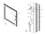
- the restrictor 10 of the present invention has been designed primarily for use with an opening panel such as window 12 which can be opened relative to its surrounding frame 14.
- the window 12 is a pivoting window, but it will be understood that the restrictor 10 could alternatively be used upon a tilt and turn window, or a sliding window, or a door, as desired.
- the restrictor 10 includes a flexible cable 16 in the form of a multi-stranded wire sheathed in a plastic covering, so that this embodiment matches the form of known cable restrictors.
- the restrictor 10 like the known cable restrictors, is not primarily intended as a security product, notwithstanding that it does increase the security of the window 12. Instead, the restrictor is designed primarily to provide additional safety, for example for windows in high-rise buildings where it is desired to prevent the inadvertent full opening of the window, for example by young children.
- the restrictor 10 when the restrictor 10 is in its operative position as shown in Figs. 1 and 2 , the window 10 may be only partially opened before the cable 16 becomes taut and further opening movement is prevented. In order to permit full opening of the window 12 the restrictor 10 must be released, as explained below.
- the restrictor 10 comprises a first housing 20 and a second housing 22.
- the first housing 20 comprises a first fixing part 24 and a first mounting part 26.
- the second housing comprises a second fixing part 30 and a second mounting part 32.
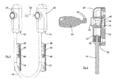
- the first end 34 of the cable 16 is permanently secured to the first fixing part 24 by way of a crimped collar 36.
- the second end of the cable 16 is similarly permanently secured to the second fixing part 30.
- Other means of securing the respective ends of the cable to the fixing parts could be used if desired, it being necessary that the connection is sufficiently secure to resist attempts to forcibly open a restricted panel, and that the connection cannot easily be accessed and/or released by a person intent on disabling the restrictor.
- the first and second mounting parts 26, 32 each have a pair of mounting holes 38 by which the mounting parts may be secured to the respective panel 12 and frame 14 by suitable fixings.
- the mounting parts 26, 32 also have a pair of projecting rails 40 (only one of which can be seen in Fig.3 ), which rails cooperate with respective channels 42 in the first and second fixing parts 24, 30.
- the first fixing part 24 can be slid downwardly as viewed in Fig.3 , so as to overlie the first mounting part 26 (and the second fixing part 30 can be similarly slid downwardly to become mounted upon the second mounting part 32).
- the mounting parts 26 and 32 each carry a lock member 46.
- the lock member 46 is a resilient clip which is depressed as the respective fixing part 24, 30 is slid downwardly thereover. When the fixing part 24, 30 reaches its mounted position as shown in Figs. 1 and 2 , the resilient clip 46 opens into an undercut region 50 of the respective fixing part 24, 30 (see Fig.4 ).
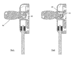
- the first fixing part 24 is moved downwardly as viewed in Figs. 3-6 , so that the cooperating rails 40 and channels 42 interengage.
- the rails and/or channels can have chamfered leading edges so as to facilitate ease of fitment.
- the first fixing part 24 is slid downwards relative to the first mounting part 26, its leading edge 52 engages and depresses the lock member 46.
- the resilient lock member 46 enters the undercut recess 50. It will be understood that subsequent attempts to remove the first fixing part 24 are resisted by the lock member 46, i.e. the lock member 46 engages the wall 54 of the undercut recess 50, preventing upwards relative sliding movement of the first fixing part 24.
- the key 56 used in this embodiment has only minor security features, specifically two depressions 60 which cooperate with corresponding formations (not shown) within the keyhole 58.
- the key 56 and keyhole 58 can be made more complex whereby to increase the security offered, if desired.
- the key 56 is retained within the keyhole 58 by way of its engagement with wall 62 as the first fixing part 24 is removed from the first mounting part 26. It is therefore necessary to rotate the key 56 back to the position of Fig.5 in order to remove the key.
- Figs. 4-6 only show the first fixing part 24 and the first mounting part 26, it will be understood that the form of the second fixing part and the second mounting part are similar, and perhaps identical. Since, however, it is not necessary (or desirable) for the second fixing part to be releasable, a key is not provided for the second housing 22. Instead, the keyhole 58 of the second fixing part 30 is ideally closed and obscured by a plug 64 so as to prevent access to the lock member of the second mounting part 32. In addition, a screw or other fastener (such as the screw 66 shown in Fig.3 ) could be fitted through the keyhole 58, through the second mounting part 32, and into the underlying frame 14, so as to substantially permanently secure the second fixing part 30 to the second mounting part 32.
- a screw or other fastener such as the screw 66 shown in Fig.3
- the lock member 46 will not be required. It is nevertheless desirable to include the lock member in the second mounting part 32 so as to make the first and second mounting parts identical and thereby totally interchangeable, even if the lock member is a separate component to the remainder of the mounting part and is assembled thereto.
- a control button (not shown) could be mounted within the keyhole 58.
- the control button could for example carry a resilient tang which locates underneath the wall 62 so as to retain the control button in place. Depression of the control button could directly depress the lock member 46, but preferably rotation of the control button through approximately 180° would be required to depress the lock member in a similar fashion to rotation of the key as described in relation to Figs. 5 and 6 .
- the manufacturer of the restrictor 10 could therefore provide a kit of parts to the customer, the kit comprising a flexible cable 16 permanently secured to first and second fixing parts 24, 30; two mounting parts 26, 32; at least one lock member 46 for the first mounting part 26 (if the lock member 46 is a separate component such as that shown it may be fitted by the manufacturer or by the customer, but if the lock member is integral then preferably each of the first and second mounting parts has an integral lock member so that the mounting parts are identical); screws or other fixings allowing the customer to secure the mounting parts to the panel and its surrounding frame; a screw 66 or other fixing allowing the customer to substantially permanently secure the second fixing part 30 to the second mounting part 32; a blanking plug 64 allowing the customer to plug the keyhole 58 of the second fixing part 30 (and thereby obscure the lock member and/or securing screw if present), a key 56 and/or a control button (providing both a key and a control button will allow the customer to choose whether to operate the restrictor 10 by way of the key or the control button
- first and second fixing parts 24, 30 are interchangeable, so that the first fixing part 24 can be mounted to the first or to the second mounting part 26, 32, and vice versa. It is therefore not necessary for the customer to fit a particular mounting part to the frame 14 or panel 12.
- first and second fixing parts 24, 30 can be identical, and also that the first and second mounting parts 26, 32 can be identical, so that the number of plastic mouldings (if made from plastic), or the number of metallic castings (if made from metal), is minimised.
Landscapes
- Engineering & Computer Science (AREA)
- Mechanical Engineering (AREA)
- Lock And Its Accessories (AREA)
- Installation Of Indoor Wiring (AREA)
Applications Claiming Priority (1)
| Application Number | Priority Date | Filing Date | Title |
|---|---|---|---|
| GBGB1220866.6A GB201220866D0 (en) | 2012-11-20 | 2012-11-20 | Cable restictor |
Publications (2)
| Publication Number | Publication Date |
|---|---|
| EP2733289A2 true EP2733289A2 (fr) | 2014-05-21 |
| EP2733289A3 EP2733289A3 (fr) | 2017-12-27 |
Family
ID=47521443
Family Applications (1)
| Application Number | Title | Priority Date | Filing Date |
|---|---|---|---|
| EP13192771.7A Withdrawn EP2733289A3 (fr) | 2012-11-20 | 2013-11-13 | Dispositif d'arrêt pour ouverture et kit d'assemblage d'un dispositif d'arrêt |
Country Status (2)
| Country | Link |
|---|---|
| EP (1) | EP2733289A3 (fr) |
| GB (2) | GB201220866D0 (fr) |
Cited By (3)
| Publication number | Priority date | Publication date | Assignee | Title |
|---|---|---|---|---|
| CN104727672A (zh) * | 2015-01-22 | 2015-06-24 | 温州金钥匙锁业有限公司 | 门窗开距限位装置 |
| EP3095936A1 (fr) * | 2015-05-22 | 2016-11-23 | J. Banks & Co. Limited | Réducteur de fenêtre |
| LT6760B (lt) | 2019-02-05 | 2020-09-10 | Stankevičius Ramūnas | Kilpinis skląstis |
Families Citing this family (3)
| Publication number | Priority date | Publication date | Assignee | Title |
|---|---|---|---|---|
| GB2549527A (en) * | 2016-04-22 | 2017-10-25 | New Star Door Controls Ltd | Restrictor |
| US11060330B2 (en) | 2018-05-15 | 2021-07-13 | Elbee Pty Ltd. | Tether lock |
| USD938257S1 (en) | 2018-05-15 | 2021-12-14 | Elbee Pty Ltd. | Lock |
Citations (5)
| Publication number | Priority date | Publication date | Assignee | Title |
|---|---|---|---|---|
| US4993760A (en) * | 1990-02-26 | 1991-02-19 | Motohiro Gotanda | Door chain-locking device |
| GB2263934A (en) | 1992-02-07 | 1993-08-11 | Banks J & Co Ltd | Releasable safety catch |
| GB2391901A (en) | 2002-06-21 | 2004-02-18 | Banks J & Co Ltd | Lockable stay |
| GB2405442A (en) * | 2003-08-29 | 2005-03-02 | Simon Perry | Window opening restraint |
| EP2085546A2 (fr) | 2008-01-24 | 2009-08-05 | J. Banks & Co. Ltd. | Arrêt de fenêtre |
Family Cites Families (10)
| Publication number | Priority date | Publication date | Assignee | Title |
|---|---|---|---|---|
| US3125875A (en) * | 1964-03-24 | Chain door lock | ||
| US795882A (en) * | 1905-03-15 | 1905-08-01 | Richard Thomas Atkin | Chain door-bolt lock. |
| GB367730A (en) * | 1931-08-25 | 1932-02-25 | Frederick Charles Smith | Safety window chain |
| US3738694A (en) * | 1971-08-16 | 1973-06-12 | Nat Mfg Co | Chain door fastener |
| US4559677A (en) * | 1984-05-31 | 1985-12-24 | Tracy Richard J | Stretchable tie-down device |
| JPS6191964A (ja) * | 1984-10-12 | 1986-05-10 | Nec Ic Microcomput Syst Ltd | Mos電界効果トランジスタ |
| US5467507A (en) * | 1993-09-17 | 1995-11-21 | Emhart Inc. | Polymer cable check strap |
| US20050104386A1 (en) * | 2003-11-19 | 2005-05-19 | Underwood Bryan K. | Black belt |
| GB2441176A (en) * | 2006-08-25 | 2008-02-27 | Assa Abloy Ltd | Door Restrictor |
| GB201013582D0 (en) * | 2010-08-13 | 2010-09-29 | Lane Andrew J | Opening restrictor |
-
2012
- 2012-11-20 GB GBGB1220866.6A patent/GB201220866D0/en not_active Ceased
-
2013
- 2013-11-13 GB GB201320001A patent/GB2508986B/en active Active
- 2013-11-13 EP EP13192771.7A patent/EP2733289A3/fr not_active Withdrawn
Patent Citations (5)
| Publication number | Priority date | Publication date | Assignee | Title |
|---|---|---|---|---|
| US4993760A (en) * | 1990-02-26 | 1991-02-19 | Motohiro Gotanda | Door chain-locking device |
| GB2263934A (en) | 1992-02-07 | 1993-08-11 | Banks J & Co Ltd | Releasable safety catch |
| GB2391901A (en) | 2002-06-21 | 2004-02-18 | Banks J & Co Ltd | Lockable stay |
| GB2405442A (en) * | 2003-08-29 | 2005-03-02 | Simon Perry | Window opening restraint |
| EP2085546A2 (fr) | 2008-01-24 | 2009-08-05 | J. Banks & Co. Ltd. | Arrêt de fenêtre |
Cited By (4)
| Publication number | Priority date | Publication date | Assignee | Title |
|---|---|---|---|---|
| CN104727672A (zh) * | 2015-01-22 | 2015-06-24 | 温州金钥匙锁业有限公司 | 门窗开距限位装置 |
| CN104727672B (zh) * | 2015-01-22 | 2016-07-06 | 温州金钥匙锁业有限公司 | 门窗开距限位装置 |
| EP3095936A1 (fr) * | 2015-05-22 | 2016-11-23 | J. Banks & Co. Limited | Réducteur de fenêtre |
| LT6760B (lt) | 2019-02-05 | 2020-09-10 | Stankevičius Ramūnas | Kilpinis skląstis |
Also Published As
| Publication number | Publication date |
|---|---|
| EP2733289A3 (fr) | 2017-12-27 |
| GB201220866D0 (en) | 2013-01-02 |
| GB201320001D0 (en) | 2013-12-25 |
| GB2508986A (en) | 2014-06-18 |
| GB2508986B (en) | 2019-12-25 |
Similar Documents
| Publication | Publication Date | Title |
|---|---|---|
| EP2733289A2 (fr) | Dispositif d'arrêt pour ouverture et kit d'assemblage d'un dispositif d'arrêt | |
| US5570543A (en) | Adjustable, removable child window guard | |
| CA2219076C (fr) | Actionneur de verrou de niveau avec la surface sur laquelle il est installe | |
| EP3228789A1 (fr) | Limiteur de câble | |
| GB0420651D0 (en) | Safety gate assembly | |
| US3953939A (en) | Movable grill guard | |
| EP2264262B1 (fr) | Dispositif de fermeture pour système de fermeture à poignée et similaires | |
| GB2527920A (en) | Cable restrictor and method of installation | |
| US5934020A (en) | Window lock and guard | |
| JP2005314952A (ja) | 上下分割ドア | |
| KR20080090951A (ko) | 손낌방지안전도어 | |
| KR20170062768A (ko) | 외관이 미려하고 설치가 용이한 손 끼임 방지용 안전도어 | |
| AU780561B2 (en) | A catch | |
| US8881561B2 (en) | Security device for a window handle or door handle | |
| US5474343A (en) | Security device for a door | |
| US20070029817A1 (en) | Safety lock | |
| KR101445018B1 (ko) | 도어 프레임의 연결구조체 | |
| AU702496B2 (en) | Releasable locking assembly | |
| KR200357485Y1 (ko) | 강화유리 출입문 안전커버 | |
| CN101435297B (zh) | 铝门窗防盗及横拉开启限制锁 | |
| EP3095936B1 (fr) | Réducteur de fenêtre | |
| US20090165389A1 (en) | Window Lock and Method of Use | |
| CN102061850A (zh) | 扳扣式窗户开口限制器 | |
| AU2008202884A1 (en) | Slide stopping device | |
| KR20150056402A (ko) | 도어의 안전장치 |
Legal Events
| Date | Code | Title | Description |
|---|---|---|---|
| PUAI | Public reference made under article 153(3) epc to a published international application that has entered the european phase |
Free format text: ORIGINAL CODE: 0009012 |
|
| 17P | Request for examination filed |
Effective date: 20131113 |
|
| AK | Designated contracting states |
Kind code of ref document: A2 Designated state(s): AL AT BE BG CH CY CZ DE DK EE ES FI FR GB GR HR HU IE IS IT LI LT LU LV MC MK MT NL NO PL PT RO RS SE SI SK SM TR |
|
| AX | Request for extension of the european patent |
Extension state: BA ME |
|
| PUAL | Search report despatched |
Free format text: ORIGINAL CODE: 0009013 |
|
| AK | Designated contracting states |
Kind code of ref document: A3 Designated state(s): AL AT BE BG CH CY CZ DE DK EE ES FI FR GB GR HR HU IE IS IT LI LT LU LV MC MK MT NL NO PL PT RO RS SE SI SK SM TR |
|
| AX | Request for extension of the european patent |
Extension state: BA ME |
|
| RIC1 | Information provided on ipc code assigned before grant |
Ipc: E05C 17/36 20060101AFI20171123BHEP |
|
| R17P | Request for examination filed (corrected) |
Effective date: 20180403 |
|
| RBV | Designated contracting states (corrected) |
Designated state(s): AL AT BE BG CH CY CZ DE DK EE ES FI FR GB GR HR HU IE IS IT LI LT LU LV MC MK MT NL NO PL PT RO RS SE SI SK SM TR |
|
| 17Q | First examination report despatched |
Effective date: 20180530 |
|
| STAA | Information on the status of an ep patent application or granted ep patent |
Free format text: STATUS: THE APPLICATION IS DEEMED TO BE WITHDRAWN |
|
| 18D | Application deemed to be withdrawn |
Effective date: 20181010 |