EP2733304B1 - Ensemble d'entrée - Google Patents
Ensemble d'entrée Download PDFInfo
- Publication number
- EP2733304B1 EP2733304B1 EP14153219.2A EP14153219A EP2733304B1 EP 2733304 B1 EP2733304 B1 EP 2733304B1 EP 14153219 A EP14153219 A EP 14153219A EP 2733304 B1 EP2733304 B1 EP 2733304B1
- Authority
- EP
- European Patent Office
- Prior art keywords
- tubular
- inlets
- inflow
- inlet
- inflow assembly
- Prior art date
- Legal status (The legal status is an assumption and is not a legal conclusion. Google has not performed a legal analysis and makes no representation as to the accuracy of the status listed.)
- Not-in-force
Links
- 239000012530 fluid Substances 0.000 claims description 34
- 239000004215 Carbon black (E152) Substances 0.000 claims description 8
- 229930195733 hydrocarbon Natural products 0.000 claims description 8
- 150000002430 hydrocarbons Chemical class 0.000 claims description 8
- 230000000149 penetrating effect Effects 0.000 claims description 4
- 230000000712 assembly Effects 0.000 claims description 3
- 238000000429 assembly Methods 0.000 claims description 3
- 238000007789 sealing Methods 0.000 description 8
- 230000015572 biosynthetic process Effects 0.000 description 3
- 230000007423 decrease Effects 0.000 description 3
- 239000002184 metal Substances 0.000 description 3
- 239000000919 ceramic Substances 0.000 description 2
- 239000002131 composite material Substances 0.000 description 1
- 230000003247 decreasing effect Effects 0.000 description 1
- 238000005553 drilling Methods 0.000 description 1
- 230000002708 enhancing effect Effects 0.000 description 1
- 238000012986 modification Methods 0.000 description 1
- 230000004048 modification Effects 0.000 description 1
- 229920000642 polymer Polymers 0.000 description 1
Images





Classifications
-
- E—FIXED CONSTRUCTIONS
- E21—EARTH OR ROCK DRILLING; MINING
- E21B—EARTH OR ROCK DRILLING; OBTAINING OIL, GAS, WATER, SOLUBLE OR MELTABLE MATERIALS OR A SLURRY OF MINERALS FROM WELLS
- E21B34/00—Valve arrangements for boreholes or wells
- E21B34/06—Valve arrangements for boreholes or wells in wells
- E21B34/14—Valve arrangements for boreholes or wells in wells operated by movement of tools, e.g. sleeve valves operated by pistons or wire line tools
-
- E—FIXED CONSTRUCTIONS
- E21—EARTH OR ROCK DRILLING; MINING
- E21B—EARTH OR ROCK DRILLING; OBTAINING OIL, GAS, WATER, SOLUBLE OR MELTABLE MATERIALS OR A SLURRY OF MINERALS FROM WELLS
- E21B21/00—Methods or apparatus for flushing boreholes, e.g. by use of exhaust air from motor
- E21B21/10—Valve arrangements in drilling-fluid circulation systems
- E21B21/103—Down-hole by-pass valve arrangements, i.e. between the inside of the drill string and the annulus
Definitions
- the present invention relates to an assembly for controlling fluid flow between a hydrocarbon reservoir and a production casing in a well, comprising a first tubular having at least a first and a second inlet, and a second tubular rotatable within the first tubular, having a wall and an outlet penetrating the wall.
- the invention also relates to a downhole completion.
- This may for instance be performed by arranging a sliding element on the inside of the inflow opening.
- the sliding element may be prevented from sliding since scale and other residues may be deposited in the designated sliding areas, having the consequence that the opening or closing of a specific inflow opening cannot be performed.
- a further disadvantage is that one or more inlets may be blocked and hence out of function due to scales and residues.
- a sleeve valve device is known. It also known to use rotating sleeves which may be rotated in relation to a stationary tubular, the sleeve and the tubular both being provided with openings, wherein the sleeve is rotated until all the openings are aligned.
- the prior rotating sleeve solutions are adapted to either open or close all openings at the same time, i.e. they function as an on/off valve.
- an inflow assembly for controlling fluid flow between a hydrocarbon reservoir and a production casing in a well, comprising:
- the first tubular may comprise a plurality of inlets.
- the second tubular may comprise a plurality of outlets to allow for alignment of several inlets and outlets.
- the second tubular may comprise at least one recess accessible from within, the recess being adapted to receive a key tool for rotating the second tubular.
- Said valve may be an inflow control valve.
- a throttle may be arranged in one or more inlet(s).
- the one or more inlet(s) may comprise a flow restrictor.
- the present invention relates to a dowhole completion comprising a casing string and one or more of the inflow assembly/assemblies described above.
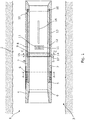
- Fig. 1 shows a longitudinal cross-sectional view of an inflow assembly 1 for controlling fluid flow between a hydrocarbon reservoir 2 and a production casing in a well 3.
- the inflow assembly comprises a first tubular 4 having twelve inlets 5 and a first wall 6 having twelve first axial channels 7 extending in the first wall 6 from the inlets 5.
- axial channels is meant that the channels extend in an axial direction in relation to the inflow assembly.
- the inflow assembly 1 also comprises a second tubular 8 having a first end 9 and a second end 10 and, in this view, six outlets 11. Even though the second tubular only shows six outlets 11, the number of outlets is actually the same as in the first tubular 4, i.e. 12 outlets.
- the second tubular 8 is rotatable within the first tubular 4 and has a second wall 12 having twelve second axial channels (not shown) extending in the second wall 12 from the first end 9 to the outlet 11.
- each outlet has its own second axial channel.
- the second tubular 8 is arranged in an inner circumferential recess 13 in the first wall 6 of the first tubular 4 so that when the second tubular 8 is arranged in the recess, the second tubular 8 will not decrease the overall inner diameter of the inflow assembly and thereby the casing string.
- the second tubular 8 is rotatable in relation to the first tubular 4 at least between a first position, in which the first channel 7 and second channel (not shown) are in alignment for allowing fluid to flow from the reservoir into the casing via the first end 9 of the second tubular 8, and a second position (the position shown in Fig. 1 ), in which the first channel 7 and second channel (not shown) are out of alignment so that fluid is prevented from flowing into the casing.
- the inflow assembly 1 also comprises a first packer 14 which is arranged between the first tubular 4 and the first end 9 of the second tubular 8.
- the packer 14 extends around the inner circumferential recess 13 and has an inner diameter which is substantially the same as that of the second tubular.
- the packer 14 has the same number of through-going packer channels 15 as there are first axial channels, i.e. in this embodiment twelve, the packer channels 15 being aligned with the first axial channels 7.
- the packer is fixedly connected with the first tubular so that the packer channels 15 are fluidly connected with first axial channels.
- the packer is ring-shaped, and the through-going packer channels 15 extend through the packer along the axial extension of the first tubular.
- the packer 14 is preferably made of ceramics, whereby it is possible to make the contact surfaces of the packer 14 smooth, which enhances the sealing properties of the packer 14, since the smooth contact surface may be pressed closer to the opposite surface which is the first end 9 of the second tubular 8.
- the packer may be made of metal, composites, polymers or the like.
- a second packer 16 is arranged between the first tubular 4 and the second end 10 of the second tubular 8.
- the second packer is omitted, whereby the second end 10 of the second tubular 8 faces the first wall of the first tubular 4.
- a first spring element 17 is arranged between the first packer 14 and the first tubular 4.
- the spring element 17 will be described in connection with Figs. 4 and 5 below.
- the second tubular 8 comprises at least one recess 18 accessible from within, the recess 18 being adapted to receive a key tool (not shown) for rotating the second tubular 8 in relation to first tubular 4.
- the inflow assembly 1 is adapted to be inserted and form part of a casing string, thus forming a cased completion (not shown).
- the ends of the inflow assembly 1 are adapted to be connected with another casing element by conventional connection means, for instance by means of a threaded connection.
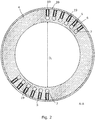
- Fig. 2 shows a cross-sectional view of the first tubular 4 taken at A-A in Fig. 1 .
- the twelve inlets 5 are shown in two groups, each having six inlets. The two groups are positioned diametrically opposite each other.
- the inlets 5 extend in a radial direction from the exterior of the first tubular to the first axial channels 7.
- the first axial channels 7 are extending in the axial direction of the first tubular 4 and are preferably made by drilling the channels in the first wall 6.
- flow restrictors 19 are arranged in the inlets 5 for restricting or throttle the inflow of fluid into the first channels 7.
- the flow restrictors 19 may be hard metal inserts.
- a screen 20 is arranged around the inlets 5 for protecting the inlets 5 as well as the flow restrictors and valves arranged in the inlets, when the inflow assembly is not in operation.
- the screen 20 may be rotatable or slidable.
- Fig. 3 the packer 14 is shown in a cross-sectional view.
- the packer channels 15 are positioned in the same manner as the two groups of inlets, as described in connection with Fig. 2 .
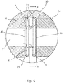
- Figs. 4 and 5 show an embodiment of the spring element 17.
- the spring element 17 is shown in a cross-sectional view taken at B-B in Fig. 5 .
- Fig. 5 shows an enlarged longitudinal cross-sectional view of the spring element 17.
- the spring element 17 is positioned between the wall 6 of the first tubular 4 and the packer 14.
- the spring element 17 is placed in the same inner circumferential recess 13 as the packer 14 and the second tubular (not shown).
- the spring element is circular and is squeezed in between the first packer and the first tubular, providing a sealing connection with both the first packer and the first tubular.
- the spring element is ring-shaped having an inner spring diameter D is substantially equal to an inner diameter D i of the first tubular.
- the spring element 17 comprises a plurality of holes 40 for providing fluid communication between the first axial channel and the second axial channel.
- the spring element is fixedly connected with the first tubular 4 and is arranged between the first tubular and the packer and thereby connects the packer and the first tubular 4 so that the first axial channel, the holes in the first spring element 17 and the through-going packer channels 15 are aligned. Access of fluid from the reservoir is thus determined by the position of the second tubular in relation to the packer and thus the first tubular.
- the holes of the spring element extend through the spring element along the axial extension of the first tubular.
- the packer is also ring-shaped having an inner packer diameter D ip which is substantially equal to an inner diameter of the first tubular so that the inner diameter of the tubular is not decreased.
- the spring element 17 is bellows-shaped, as shown in Figs. 4A, 4B, 4C and 5 , and is preferably made of metal.
- the bellows-shaped spring element 17 comprises axial grooves 21 in which the fluid flow (indicated by the arrows) can force the spring element 17 against the packer 14, whereby the fluid flow and pressure exert an axial force on the packer 14 so that the packer is pressed against the second tubular (not shown), providing enhanced sealing properties.
- the bellows-shaped spring element has a first outer face abutting the first tubular, providing a sealing connection with the first tubular so that fluid flows in the first axial channel of the first tubular through the hole in the spring element.
- the spring element 17 has a surface area which is larger than a cross-section of the axial groove, which again results in the fluid pressure present in the first channel 7 exerting a force on the surface area, whereby the force presses the packer 14 against the second tubular for enhancing the sealing.
- Figs. 6a and 6b show two longitudinal cross-sectional views of another embodiment of an inflow assembly 1.
- the inflow assembly 1 is partly identical to the embodiment shown in Fig. 1 .
- the first tubular 4 further comprises six second inlets 22 and six third axial channels 23 extending in the first wall 6 from the second inlets 22.
- the second tubular 8 further comprises six second outlets 24 and has six fourth axial channels (not shown) extending in the second wall 12 from the second end 10.
- the second tubular 8 is also rotatable in relation to the first tubular 4 at least between a first position (not shown), in which the third and fourth channels are in alignment for allowing fluid to flow from the reservoir into the casing via the second end 10 of the second tubular, and a second position (the position shown in Figs. 6a and 6b ), in which the third and fourth channels are out of alignment so that fluid is prevented from flowing into the casing from the second end 10 of the second tubular 8.
- the left side of the inflow assembly 1 is also shown in the second position in which the first and second channels are out of alignment so that fluid is prevented from flowing into the casing from the first end 9 of the second tubular 8.
- the embodiment shown in Figs. 6a and 6b has the advantage that one rotatable second tubular 8 may control inflow of fluid into the casing from more areas than the inflow assembly shown in Fig. 1 . This is obtained by each end of the second tubular being aligned with inlets arranged in the first tubular 4 on each side of the second tubular 8.
- both the inlets and the outlets as well as the intermediate channels may be arranged in the first tubular and second tubular, respectively, with predetermined distances between them around the periphery of the first and second tubulars, so that the operator of the inflow assembly 1 has the possibility of choosing which inlets to open and which to close by rotating the second tubular 8 to the position in which the channels are in alignment.
- a second packer 25 is arranged between the first tubular 4 and the second end 10 of the second tubular 8, the packer 25 having at least one through-going packer channel 26 aligned with the third axial channel 23.
- the second packer 25 is preferably made of ceramics.
- a second spring element 27 is arranged between the second packer 25 and the first tubular 4 and has a design similar to that of the first spring element, described in connection with Figs. 4 and 5 above.
- the second inlets 22 have a valve arranged therein, preferably a constant flow valve or inflow control valve, which will be described briefly in connection with Fig. 7 below.
- the inlets on the left side of the second tubular 8 have flow restrictors arranged therein, and the inlets on the right side of the second tubular 8 have constant flow valves arranged therein.
- the first tubular may comprise a plurality of inlets and/or a plurality of first axial channels as required.
- the second tubular 8 may comprise a plurality of second axial channels as well as outlets.
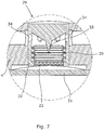
- Fig. 7 shows one embodiment of an inflow control valve or a constant flow valve.
- the inflow control valve 29 comprises a screen 31 arranged in the inlet 22 of a housing 32 and a spring element 30 in the form of a bellows.
- the housing 32 has a projection 33 tapering from the end of the housing 32 comprising the outlet 34 towards the inlet 22.
- the bellows have a valve opening (not shown) which the projection penetrates so that when the fluid flows in through the inlet 22 of the valve from the formation, the pressure of the fluid forces the bellows to extend, causing the valve opening to travel towards the outlets 34, and the valve opening decreases as the bellows travel due to the projection tapering and filling out part of the valve opening. In this way, high pressure caused from the fluid pressure in the formation decreases the valve opening, and thus the inflow of fluid is controlled. As the pressure in the formation drops, the bellows are retracted again and more fluid is let through the valve opening.
- FIG. 8 Another embodiment of an inflow assembly 1 is shown in Fig. 8 .
- the inflow assembly 1 in this embodiment comprises the same features as the embodiment shown in Figs. 6a and 6b .
- the inflow assembly also comprises a third tubular 28 which is rotatable within the first tubular 4.
- the third tubular 28 is rotatable in an inner circumferential recess 35 arranged in the first tubular 4.
- the first tubular comprises a number of first openings 36 in the form of axial longitudinal grooves.
- the third tubular 28 also comprises the same number of second openings 37 as the first tubular 4.
- the third tubular 28 is rotatable in relation to the first tubular 4 at least between a first position, in which the first and second openings 36, 37 are in alignment for allowing access through the openings 36, 37, and a second position in which the first and second openings 36, 37 are out of alignment so that access through the third tubular 28 is impossible.
- the third tubular 28 is arranged to the right of the second inlets 22 of the first tubular 4. However, it may also be arranged to the left of the first inlets 5.
- the third tubular 28 may for instance be a fracturing port or a rotational sleeve fracturing valve.
- the inflow assembly may comprise a plurality of additional features or elements which may be incorporated for fulfilling different purposes and requirements. Accordingly, the inflow assembly may have multiple functionalities.
- an inflow assembly 101 for controlling fluid flow between a hydrocarbon reservoir and a production casing in a well comprises a first tubular 104 which in this embodiment has four inlets 105.
- the inflow assembly 101 comprises a second tubular 108 which is rotatable within the first tubular 104 and has a wall 106 and, in this embodiment, four outlets 111 penetrating the wall 106.
- the second tubular 108 is rotatable from a first position (the position shown in Fig. 9a ) in which the outlets 111 are aligned with at least one of the inlets 105, and the wall 106 is opposite the other inlets, to a second position (not shown) in which the one or more outlet(s) 111 may be aligned with one or more of the second inlets, and the wall is opposite the first inlet, or to a third position (not shown) in which the wall is opposite the first and the second inlets.
- one or more inlets in the first tubular 104 may be aligned with one or more outlets in the second tubular 108, or even be in non-alignment, whereby the inflow assembly is closed for inflow of fluid.
- the operator may then easily rotate the second tubular 108 so that the desired inflow of fluid matching the specific requirements is obtained.
- Fig. 9b it is shown that all four inlets 105 and outlets 111 are in alignment, and hence all open for inflow.
- the first tubular will always at least comprise a first and a second inlet
- the second tubular 108 will also at least comprise a first outlet.
- the first tubular may comprise a plurality of inlets and the second tubular comprises a plurality of outlets so that several inlets and outlets can be in alignment.
- the inlets are shown as openings.
- the openings may comprise flow restrictors, throttles or valves, such as inflow control valves, as described in connection with Fig. 7 above.
- the second tubular may comprise at least one recess (not shown) accessible from within, the recess being adapted to receive a key tool for rotating the second tubular.
- the present invention also relates to a downhole completion (not shown) which comprises a casing string and one or more of the inflow assembly/assemblies having the features described above.
Landscapes
- Engineering & Computer Science (AREA)
- Geology (AREA)
- Life Sciences & Earth Sciences (AREA)
- Mining & Mineral Resources (AREA)
- Physics & Mathematics (AREA)
- Environmental & Geological Engineering (AREA)
- Fluid Mechanics (AREA)
- General Life Sciences & Earth Sciences (AREA)
- Geochemistry & Mineralogy (AREA)
- Mechanical Engineering (AREA)
- Multiple-Way Valves (AREA)
- Pipe Accessories (AREA)
- Joints Allowing Movement (AREA)
- Loading And Unloading Of Fuel Tanks Or Ships (AREA)
Claims (9)
- Ensemble d'écoulement entrant pour commander un écoulement de fluide entre un réservoir d'hydrocarbure et un tubage de production dans un puits, comprenant :- une première tubulure (104) ayant au moins une première et une seconde entrée (105),- une seconde tubulure (108) qui peut tourner dans la première tubulure (104), ayant une paroi (106) et une sortie (111) pénétrant dans la paroi (106) etcaractérisé en ce que la seconde tubulure (108) peut tourner d'une première position, dans laquelle le sortie (111) est alignée sur la première entrée (105) et la paroi (106) est opposée à la seconde entrée, jusque dans une deuxième position, dans laquelle le sortie (111) est alignée sur la seconde entrée et la paroi (106) est opposée à la première entrée, ou dans une troisième position, dans laquelle la paroi (106) est opposée aux première et seconde entrées.
- Ensemble d'écoulement entrant selon la revendication 1, dans lequel la première tubulure (104) comprend une pluralité d'entrées (105).
- Ensemble d'écoulement entrant selon la revendication 2, dans lequel la seconde tubulure (108) comprend une pluralité de sorties (111) pour permettre un alignement de plusieurs entrées et sorties.
- Ensemble d'écoulement entrant selon l'une quelconque des revendications précédentes, dans lequel la seconde tubulure (8) comprend au moins un évidement (18) accessible de l'intérieur, l'évidement (18) étant à même de recevoir un outil à clé pour faire tourner la seconde tubulure (8).
- Ensemble d'écoulement entrant selon l'une quelconque des revendications précédentes, dans lequel une soupape peut être agencée dans une ou plusieurs entrées.
- Ensemble d'écoulement entrant selon la revendication 5, dans lequel la soupape est une soupape de commande d'écoulement entrant.
- Ensemble d'écoulement entrant selon l'une quelconque des revendications précédentes, dans lequel un étranglement peut être aménagé dans une ou plusieurs entrées.
- Ensemble d'écoulement entrant selon l'une quelconque des revendications précédentes, dans lequel les une ou plusieurs entrées comprennent un restricteur d'écoulement.
- Complétion de puits comprenant une colonne de tubage et un ou plusieurs des ensembles d'écoulement selon l'une quelconque des revendications 1 à 8.
Applications Claiming Priority (3)
| Application Number | Priority Date | Filing Date | Title |
|---|---|---|---|
| EP10195562A EP2466058A1 (fr) | 2010-12-17 | 2010-12-17 | Ensemble d'entrée |
| EP11802703.6A EP2652240B1 (fr) | 2010-12-17 | 2011-12-16 | Ensemble d'admission |
| PCT/EP2011/073099 WO2012080485A1 (fr) | 2010-12-17 | 2011-12-16 | Ensemble de débit entrant |
Related Parent Applications (2)
| Application Number | Title | Priority Date | Filing Date |
|---|---|---|---|
| EP11802703.6A Division-Into EP2652240B1 (fr) | 2010-12-17 | 2011-12-16 | Ensemble d'admission |
| EP11802703.6A Division EP2652240B1 (fr) | 2010-12-17 | 2011-12-16 | Ensemble d'admission |
Publications (3)
| Publication Number | Publication Date |
|---|---|
| EP2733304A1 EP2733304A1 (fr) | 2014-05-21 |
| EP2733304B1 true EP2733304B1 (fr) | 2019-01-16 |
| EP2733304B8 EP2733304B8 (fr) | 2019-12-11 |
Family
ID=43781883
Family Applications (3)
| Application Number | Title | Priority Date | Filing Date |
|---|---|---|---|
| EP10195562A Withdrawn EP2466058A1 (fr) | 2010-12-17 | 2010-12-17 | Ensemble d'entrée |
| EP11802703.6A Not-in-force EP2652240B1 (fr) | 2010-12-17 | 2011-12-16 | Ensemble d'admission |
| EP14153219.2A Not-in-force EP2733304B8 (fr) | 2010-12-17 | 2011-12-16 | Ensemble d'entrée |
Family Applications Before (2)
| Application Number | Title | Priority Date | Filing Date |
|---|---|---|---|
| EP10195562A Withdrawn EP2466058A1 (fr) | 2010-12-17 | 2010-12-17 | Ensemble d'entrée |
| EP11802703.6A Not-in-force EP2652240B1 (fr) | 2010-12-17 | 2011-12-16 | Ensemble d'admission |
Country Status (10)
| Country | Link |
|---|---|
| US (1) | US9322244B2 (fr) |
| EP (3) | EP2466058A1 (fr) |
| CN (1) | CN103261570B (fr) |
| AU (1) | AU2011343280B2 (fr) |
| BR (1) | BR112013014954A2 (fr) |
| CA (1) | CA2821835A1 (fr) |
| DK (2) | DK2733304T3 (fr) |
| MX (1) | MX2013006904A (fr) |
| RU (1) | RU2580122C2 (fr) |
| WO (1) | WO2012080485A1 (fr) |
Families Citing this family (13)
| Publication number | Priority date | Publication date | Assignee | Title |
|---|---|---|---|---|
| CN103221626B (zh) | 2010-09-09 | 2015-07-15 | 国民油井华高有限公司 | 具有地层接口构件和控制系统的井下旋转式钻井设备 |
| US8869916B2 (en) | 2010-09-09 | 2014-10-28 | National Oilwell Varco, L.P. | Rotary steerable push-the-bit drilling apparatus with self-cleaning fluid filter |
| US8919440B2 (en) * | 2012-09-24 | 2014-12-30 | Kristian Brekke | System and method for detecting screen-out using a fracturing valve for mitigation |
| AU2014296122B2 (en) | 2013-07-31 | 2017-09-21 | Schlumberger Technology B.V. | Sand control system and methodology |
| CN103527135B (zh) * | 2013-10-18 | 2016-08-24 | 西南石油大学 | 双缸压缩式封隔器 |
| US10156123B2 (en) | 2014-10-28 | 2018-12-18 | Halliburton Energy Services, Inc. | Inflow control device adjusted by rotation of a cover sleeve |
| US11078736B2 (en) * | 2017-01-20 | 2021-08-03 | Center Rock Inc. | Flow diversion sub for a down-the-hole drill hammer |
| RU173196U1 (ru) * | 2017-04-13 | 2017-08-16 | Сергей Евгеньевич Варламов | Устройство для выравнивания притока нефтяной скважины |
| RU2682388C1 (ru) * | 2017-10-10 | 2019-03-19 | Владимир Александрович Чигряй | Устройство регулирования притока флюида |
| NO344335B1 (en) | 2018-08-16 | 2019-11-04 | Advantage As | Downhole tubular sleeve valve and use of such a sleeve valve |
| CN111119764B (zh) * | 2018-11-01 | 2022-02-25 | 中国石油化工股份有限公司 | 防气侵装置和包括其的钻井管柱 |
| AU2020459959B2 (en) * | 2020-07-20 | 2025-12-04 | Halliburton Energy Services, Inc.. | Internally adjustable flow control module |
| EP4671491A3 (fr) * | 2021-08-11 | 2026-03-11 | Swellfix UK Limited | Dispositif de régulation de débit |
Family Cites Families (14)
| Publication number | Priority date | Publication date | Assignee | Title |
|---|---|---|---|---|
| US2710655A (en) * | 1952-07-19 | 1955-06-14 | J B Nelson | Rotatable port control sleeve |
| US3993130A (en) * | 1975-05-14 | 1976-11-23 | Texaco Inc. | Method and apparatus for controlling the injection profile of a borehole |
| US4103741A (en) * | 1977-06-01 | 1978-08-01 | Tool Masters, Inc. | Oil well perforation testing device |
| US4315542A (en) * | 1979-10-26 | 1982-02-16 | Dockins Jr Roy R | Mechanical tubing drain |
| US4782896A (en) * | 1987-05-28 | 1988-11-08 | Atlantic Richfield Company | Retrievable fluid flow control nozzle system for wells |
| NO20002287A (no) | 2000-04-28 | 2001-04-23 | Triangle Equipment As | Anordning ved en muffeventil og fremgangsmåte til sammenstilling av samme |
| US6644412B2 (en) * | 2001-04-25 | 2003-11-11 | Weatherford/Lamb, Inc. | Flow control apparatus for use in a wellbore |
| GB2416385B (en) * | 2004-03-16 | 2006-04-12 | Tour & Andersson Ab | Valve assembly |
| US7387165B2 (en) * | 2004-12-14 | 2008-06-17 | Schlumberger Technology Corporation | System for completing multiple well intervals |
| CA2555023A1 (fr) * | 2006-08-03 | 2008-02-03 | G. Maurice Laclare | Outil combine antirotation et regulateur de debit |
| US20080041582A1 (en) | 2006-08-21 | 2008-02-21 | Geirmund Saetre | Apparatus for controlling the inflow of production fluids from a subterranean well |
| US7673677B2 (en) * | 2007-08-13 | 2010-03-09 | Baker Hughes Incorporated | Reusable ball seat having ball support member |
| US7918275B2 (en) * | 2007-11-27 | 2011-04-05 | Baker Hughes Incorporated | Water sensitive adaptive inflow control using couette flow to actuate a valve |
| RU92905U1 (ru) | 2009-10-29 | 2010-04-10 | Общество с ограниченной ответственностью "ВОРМХОЛС" | Устройство для управления потоком жидкости, поступающим в добывающую или нагнетающую колонну скважины |
-
2010
- 2010-12-17 EP EP10195562A patent/EP2466058A1/fr not_active Withdrawn
-
2011
- 2011-12-16 DK DK14153219.2T patent/DK2733304T3/da active
- 2011-12-16 CN CN201180060632.1A patent/CN103261570B/zh not_active Expired - Fee Related
- 2011-12-16 MX MX2013006904A patent/MX2013006904A/es active IP Right Grant
- 2011-12-16 AU AU2011343280A patent/AU2011343280B2/en not_active Ceased
- 2011-12-16 DK DK11802703.6T patent/DK2652240T3/en active
- 2011-12-16 RU RU2013132390/03A patent/RU2580122C2/ru not_active IP Right Cessation
- 2011-12-16 WO PCT/EP2011/073099 patent/WO2012080485A1/fr not_active Ceased
- 2011-12-16 CA CA2821835A patent/CA2821835A1/fr not_active Abandoned
- 2011-12-16 EP EP11802703.6A patent/EP2652240B1/fr not_active Not-in-force
- 2011-12-16 US US13/994,959 patent/US9322244B2/en not_active Expired - Fee Related
- 2011-12-16 BR BR112013014954A patent/BR112013014954A2/pt not_active IP Right Cessation
- 2011-12-16 EP EP14153219.2A patent/EP2733304B8/fr not_active Not-in-force
Non-Patent Citations (1)
| Title |
|---|
| None * |
Also Published As
| Publication number | Publication date |
|---|---|
| MX2013006904A (es) | 2013-07-15 |
| BR112013014954A2 (pt) | 2016-09-13 |
| AU2011343280A1 (en) | 2013-05-02 |
| AU2011343280B2 (en) | 2015-03-05 |
| DK2733304T3 (da) | 2019-05-06 |
| US9322244B2 (en) | 2016-04-26 |
| EP2466058A1 (fr) | 2012-06-20 |
| RU2580122C2 (ru) | 2016-04-10 |
| CN103261570B (zh) | 2016-06-08 |
| EP2652240B1 (fr) | 2014-10-15 |
| US20130277043A1 (en) | 2013-10-24 |
| RU2013132390A (ru) | 2015-01-27 |
| EP2652240A1 (fr) | 2013-10-23 |
| WO2012080485A1 (fr) | 2012-06-21 |
| EP2733304B8 (fr) | 2019-12-11 |
| EP2733304A1 (fr) | 2014-05-21 |
| CA2821835A1 (fr) | 2012-06-21 |
| CN103261570A (zh) | 2013-08-21 |
| DK2652240T3 (en) | 2015-01-19 |
Similar Documents
| Publication | Publication Date | Title |
|---|---|---|
| EP2733304B1 (fr) | Ensemble d'entrée | |
| CA2905738C (fr) | Outil de circulation entraine par la velocite d'un fluide | |
| US6371208B1 (en) | Variable downhole choke | |
| US7575058B2 (en) | Incremental annular choke | |
| CA2581622C (fr) | Clapet anti-retour double | |
| US8316953B2 (en) | Valve | |
| US20120048556A1 (en) | Plug counter, fracing system and method | |
| EP2795052B1 (fr) | Système de production pour produire des hydrocarbures à partir d'un puits | |
| US9903180B2 (en) | Compression activated bypass valve | |
| US20200318458A1 (en) | Plug and Plug Seat System | |
| NO347934B1 (en) | Downhole flow control assemblies and methods of use | |
| US9243454B2 (en) | Apparatus for keeping a downhole drilling tool vertically aligned | |
| AU2015202993B2 (en) | An inflow assembly | |
| US20160145971A1 (en) | Alignment Apparatus for a Sliding Sleeve Subterranean Tool | |
| US9677378B2 (en) | Downhole flow control assemblies and methods of use | |
| WO2018067739A1 (fr) | Système de siège de bouchon et de bouchon amélioré | |
| CA2795029C (fr) | Appareil pour maintenir l'alignement vertical d'un outil de forage de puits |
Legal Events
| Date | Code | Title | Description |
|---|---|---|---|
| PUAI | Public reference made under article 153(3) epc to a published international application that has entered the european phase |
Free format text: ORIGINAL CODE: 0009012 |
|
| 17P | Request for examination filed |
Effective date: 20140130 |
|
| AC | Divisional application: reference to earlier application |
Ref document number: 2652240 Country of ref document: EP Kind code of ref document: P |
|
| AK | Designated contracting states |
Kind code of ref document: A1 Designated state(s): AL AT BE BG CH CY CZ DE DK EE ES FI FR GB GR HR HU IE IS IT LI LT LU LV MC MK MT NL NO PL PT RO RS SE SI SK SM TR |
|
| R17P | Request for examination filed (corrected) |
Effective date: 20141119 |
|
| RBV | Designated contracting states (corrected) |
Designated state(s): AL AT BE BG CH CY CZ DE DK EE ES FI FR GB GR HR HU IE IS IT LI LT LU LV MC MK MT NL NO PL PT RO RS SE SI SK SM TR |
|
| GRAP | Despatch of communication of intention to grant a patent |
Free format text: ORIGINAL CODE: EPIDOSNIGR1 |
|
| STAA | Information on the status of an ep patent application or granted ep patent |
Free format text: STATUS: GRANT OF PATENT IS INTENDED |
|
| INTG | Intention to grant announced |
Effective date: 20180724 |
|
| GRAS | Grant fee paid |
Free format text: ORIGINAL CODE: EPIDOSNIGR3 |
|
| GRAA | (expected) grant |
Free format text: ORIGINAL CODE: 0009210 |
|
| STAA | Information on the status of an ep patent application or granted ep patent |
Free format text: STATUS: THE PATENT HAS BEEN GRANTED |
|
| RAP1 | Party data changed (applicant data changed or rights of an application transferred) |
Owner name: WELLTEC OILFIELD SOLUTIONS AG |
|
| AC | Divisional application: reference to earlier application |
Ref document number: 2652240 Country of ref document: EP Kind code of ref document: P |
|
| AK | Designated contracting states |
Kind code of ref document: B1 Designated state(s): AL AT BE BG CH CY CZ DE DK EE ES FI FR GB GR HR HU IE IS IT LI LT LU LV MC MK MT NL NO PL PT RO RS SE SI SK SM TR |
|
| REG | Reference to a national code |
Ref country code: GB Ref legal event code: FG4D |
|
| REG | Reference to a national code |
Ref country code: CH Ref legal event code: EP |
|
| REG | Reference to a national code |
Ref country code: IE Ref legal event code: FG4D |
|
| REG | Reference to a national code |
Ref country code: DE Ref legal event code: R096 Ref document number: 602011055837 Country of ref document: DE |
|
| REG | Reference to a national code |
Ref country code: AT Ref legal event code: REF Ref document number: 1089820 Country of ref document: AT Kind code of ref document: T Effective date: 20190215 |
|
| REG | Reference to a national code |
Ref country code: NO Ref legal event code: T2 Effective date: 20190116 |
|
| REG | Reference to a national code |
Ref country code: DK Ref legal event code: T3 Effective date: 20190429 |
|
| REG | Reference to a national code |
Ref country code: NL Ref legal event code: FP |
|
| REG | Reference to a national code |
Ref country code: LT Ref legal event code: MG4D |
|
| REG | Reference to a national code |
Ref country code: AT Ref legal event code: MK05 Ref document number: 1089820 Country of ref document: AT Kind code of ref document: T Effective date: 20190116 |
|
| PG25 | Lapsed in a contracting state [announced via postgrant information from national office to epo] |
Ref country code: PT Free format text: LAPSE BECAUSE OF FAILURE TO SUBMIT A TRANSLATION OF THE DESCRIPTION OR TO PAY THE FEE WITHIN THE PRESCRIBED TIME-LIMIT Effective date: 20190516 Ref country code: FI Free format text: LAPSE BECAUSE OF FAILURE TO SUBMIT A TRANSLATION OF THE DESCRIPTION OR TO PAY THE FEE WITHIN THE PRESCRIBED TIME-LIMIT Effective date: 20190116 Ref country code: LT Free format text: LAPSE BECAUSE OF FAILURE TO SUBMIT A TRANSLATION OF THE DESCRIPTION OR TO PAY THE FEE WITHIN THE PRESCRIBED TIME-LIMIT Effective date: 20190116 Ref country code: SE Free format text: LAPSE BECAUSE OF FAILURE TO SUBMIT A TRANSLATION OF THE DESCRIPTION OR TO PAY THE FEE WITHIN THE PRESCRIBED TIME-LIMIT Effective date: 20190116 Ref country code: ES Free format text: LAPSE BECAUSE OF FAILURE TO SUBMIT A TRANSLATION OF THE DESCRIPTION OR TO PAY THE FEE WITHIN THE PRESCRIBED TIME-LIMIT Effective date: 20190116 Ref country code: PL Free format text: LAPSE BECAUSE OF FAILURE TO SUBMIT A TRANSLATION OF THE DESCRIPTION OR TO PAY THE FEE WITHIN THE PRESCRIBED TIME-LIMIT Effective date: 20190116 |
|
| PG25 | Lapsed in a contracting state [announced via postgrant information from national office to epo] |
Ref country code: GR Free format text: LAPSE BECAUSE OF FAILURE TO SUBMIT A TRANSLATION OF THE DESCRIPTION OR TO PAY THE FEE WITHIN THE PRESCRIBED TIME-LIMIT Effective date: 20190417 Ref country code: IS Free format text: LAPSE BECAUSE OF FAILURE TO SUBMIT A TRANSLATION OF THE DESCRIPTION OR TO PAY THE FEE WITHIN THE PRESCRIBED TIME-LIMIT Effective date: 20190516 Ref country code: HR Free format text: LAPSE BECAUSE OF FAILURE TO SUBMIT A TRANSLATION OF THE DESCRIPTION OR TO PAY THE FEE WITHIN THE PRESCRIBED TIME-LIMIT Effective date: 20190116 Ref country code: LV Free format text: LAPSE BECAUSE OF FAILURE TO SUBMIT A TRANSLATION OF THE DESCRIPTION OR TO PAY THE FEE WITHIN THE PRESCRIBED TIME-LIMIT Effective date: 20190116 Ref country code: RS Free format text: LAPSE BECAUSE OF FAILURE TO SUBMIT A TRANSLATION OF THE DESCRIPTION OR TO PAY THE FEE WITHIN THE PRESCRIBED TIME-LIMIT Effective date: 20190116 Ref country code: BG Free format text: LAPSE BECAUSE OF FAILURE TO SUBMIT A TRANSLATION OF THE DESCRIPTION OR TO PAY THE FEE WITHIN THE PRESCRIBED TIME-LIMIT Effective date: 20190416 |
|
| REG | Reference to a national code |
Ref country code: DE Ref legal event code: R097 Ref document number: 602011055837 Country of ref document: DE |
|
| PG25 | Lapsed in a contracting state [announced via postgrant information from national office to epo] |
Ref country code: IT Free format text: LAPSE BECAUSE OF FAILURE TO SUBMIT A TRANSLATION OF THE DESCRIPTION OR TO PAY THE FEE WITHIN THE PRESCRIBED TIME-LIMIT Effective date: 20190116 Ref country code: CZ Free format text: LAPSE BECAUSE OF FAILURE TO SUBMIT A TRANSLATION OF THE DESCRIPTION OR TO PAY THE FEE WITHIN THE PRESCRIBED TIME-LIMIT Effective date: 20190116 Ref country code: EE Free format text: LAPSE BECAUSE OF FAILURE TO SUBMIT A TRANSLATION OF THE DESCRIPTION OR TO PAY THE FEE WITHIN THE PRESCRIBED TIME-LIMIT Effective date: 20190116 Ref country code: RO Free format text: LAPSE BECAUSE OF FAILURE TO SUBMIT A TRANSLATION OF THE DESCRIPTION OR TO PAY THE FEE WITHIN THE PRESCRIBED TIME-LIMIT Effective date: 20190116 Ref country code: AT Free format text: LAPSE BECAUSE OF FAILURE TO SUBMIT A TRANSLATION OF THE DESCRIPTION OR TO PAY THE FEE WITHIN THE PRESCRIBED TIME-LIMIT Effective date: 20190116 Ref country code: AL Free format text: LAPSE BECAUSE OF FAILURE TO SUBMIT A TRANSLATION OF THE DESCRIPTION OR TO PAY THE FEE WITHIN THE PRESCRIBED TIME-LIMIT Effective date: 20190116 Ref country code: SK Free format text: LAPSE BECAUSE OF FAILURE TO SUBMIT A TRANSLATION OF THE DESCRIPTION OR TO PAY THE FEE WITHIN THE PRESCRIBED TIME-LIMIT Effective date: 20190116 |
|
| GRAT | Correction requested after decision to grant or after decision to maintain patent in amended form |
Free format text: ORIGINAL CODE: EPIDOSNCDEC |
|
| REG | Reference to a national code |
Ref country code: CH Ref legal event code: PK Free format text: BERICHTIGUNGEN Ref country code: CH Ref legal event code: PK Free format text: BERICHTIGUNG B8 |
|
| PLBE | No opposition filed within time limit |
Free format text: ORIGINAL CODE: 0009261 |
|
| STAA | Information on the status of an ep patent application or granted ep patent |
Free format text: STATUS: NO OPPOSITION FILED WITHIN TIME LIMIT |
|
| PG25 | Lapsed in a contracting state [announced via postgrant information from national office to epo] |
Ref country code: SM Free format text: LAPSE BECAUSE OF FAILURE TO SUBMIT A TRANSLATION OF THE DESCRIPTION OR TO PAY THE FEE WITHIN THE PRESCRIBED TIME-LIMIT Effective date: 20190116 |
|
| RIN2 | Information on inventor provided after grant (corrected) |
Inventor name: HALLUNDBAEK, JOERGEN Inventor name: ANDERSEN, TOMAS SUNE |
|
| 26N | No opposition filed |
Effective date: 20191017 |
|
| PG25 | Lapsed in a contracting state [announced via postgrant information from national office to epo] |
Ref country code: SI Free format text: LAPSE BECAUSE OF FAILURE TO SUBMIT A TRANSLATION OF THE DESCRIPTION OR TO PAY THE FEE WITHIN THE PRESCRIBED TIME-LIMIT Effective date: 20190116 |
|
| PG25 | Lapsed in a contracting state [announced via postgrant information from national office to epo] |
Ref country code: TR Free format text: LAPSE BECAUSE OF FAILURE TO SUBMIT A TRANSLATION OF THE DESCRIPTION OR TO PAY THE FEE WITHIN THE PRESCRIBED TIME-LIMIT Effective date: 20190116 |
|
| REG | Reference to a national code |
Ref country code: CH Ref legal event code: PL |
|
| REG | Reference to a national code |
Ref country code: BE Ref legal event code: MM Effective date: 20191231 |
|
| PG25 | Lapsed in a contracting state [announced via postgrant information from national office to epo] |
Ref country code: MC Free format text: LAPSE BECAUSE OF FAILURE TO SUBMIT A TRANSLATION OF THE DESCRIPTION OR TO PAY THE FEE WITHIN THE PRESCRIBED TIME-LIMIT Effective date: 20190116 |
|
| PG25 | Lapsed in a contracting state [announced via postgrant information from national office to epo] |
Ref country code: LU Free format text: LAPSE BECAUSE OF NON-PAYMENT OF DUE FEES Effective date: 20191216 Ref country code: IE Free format text: LAPSE BECAUSE OF NON-PAYMENT OF DUE FEES Effective date: 20191216 |
|
| PG25 | Lapsed in a contracting state [announced via postgrant information from national office to epo] |
Ref country code: BE Free format text: LAPSE BECAUSE OF NON-PAYMENT OF DUE FEES Effective date: 20191231 Ref country code: CH Free format text: LAPSE BECAUSE OF NON-PAYMENT OF DUE FEES Effective date: 20191231 Ref country code: LI Free format text: LAPSE BECAUSE OF NON-PAYMENT OF DUE FEES Effective date: 20191231 |
|
| PGFP | Annual fee paid to national office [announced via postgrant information from national office to epo] |
Ref country code: DK Payment date: 20201216 Year of fee payment: 10 Ref country code: NO Payment date: 20201222 Year of fee payment: 10 Ref country code: GB Payment date: 20201218 Year of fee payment: 10 Ref country code: FR Payment date: 20201210 Year of fee payment: 10 |
|
| PGFP | Annual fee paid to national office [announced via postgrant information from national office to epo] |
Ref country code: NL Payment date: 20201221 Year of fee payment: 10 |
|
| PG25 | Lapsed in a contracting state [announced via postgrant information from national office to epo] |
Ref country code: CY Free format text: LAPSE BECAUSE OF FAILURE TO SUBMIT A TRANSLATION OF THE DESCRIPTION OR TO PAY THE FEE WITHIN THE PRESCRIBED TIME-LIMIT Effective date: 20190116 |
|
| PGFP | Annual fee paid to national office [announced via postgrant information from national office to epo] |
Ref country code: DE Payment date: 20201221 Year of fee payment: 10 |
|
| PG25 | Lapsed in a contracting state [announced via postgrant information from national office to epo] |
Ref country code: HU Free format text: LAPSE BECAUSE OF FAILURE TO SUBMIT A TRANSLATION OF THE DESCRIPTION OR TO PAY THE FEE WITHIN THE PRESCRIBED TIME-LIMIT; INVALID AB INITIO Effective date: 20111216 Ref country code: MT Free format text: LAPSE BECAUSE OF FAILURE TO SUBMIT A TRANSLATION OF THE DESCRIPTION OR TO PAY THE FEE WITHIN THE PRESCRIBED TIME-LIMIT Effective date: 20190116 |
|
| PG25 | Lapsed in a contracting state [announced via postgrant information from national office to epo] |
Ref country code: MK Free format text: LAPSE BECAUSE OF FAILURE TO SUBMIT A TRANSLATION OF THE DESCRIPTION OR TO PAY THE FEE WITHIN THE PRESCRIBED TIME-LIMIT Effective date: 20190116 |
|
| REG | Reference to a national code |
Ref country code: DE Ref legal event code: R119 Ref document number: 602011055837 Country of ref document: DE |
|
| REG | Reference to a national code |
Ref country code: NO Ref legal event code: MMEP Ref country code: DK Ref legal event code: EBP Effective date: 20211231 |
|
| REG | Reference to a national code |
Ref country code: NL Ref legal event code: MM Effective date: 20220101 |
|
| GBPC | Gb: european patent ceased through non-payment of renewal fee |
Effective date: 20211216 |
|
| PG25 | Lapsed in a contracting state [announced via postgrant information from national office to epo] |
Ref country code: NL Free format text: LAPSE BECAUSE OF NON-PAYMENT OF DUE FEES Effective date: 20220101 |
|
| PG25 | Lapsed in a contracting state [announced via postgrant information from national office to epo] |
Ref country code: NO Free format text: LAPSE BECAUSE OF NON-PAYMENT OF DUE FEES Effective date: 20211231 Ref country code: GB Free format text: LAPSE BECAUSE OF NON-PAYMENT OF DUE FEES Effective date: 20211216 Ref country code: DE Free format text: LAPSE BECAUSE OF NON-PAYMENT OF DUE FEES Effective date: 20220701 |
|
| PG25 | Lapsed in a contracting state [announced via postgrant information from national office to epo] |
Ref country code: FR Free format text: LAPSE BECAUSE OF NON-PAYMENT OF DUE FEES Effective date: 20211231 |
|
| PG25 | Lapsed in a contracting state [announced via postgrant information from national office to epo] |
Ref country code: DK Free format text: LAPSE BECAUSE OF NON-PAYMENT OF DUE FEES Effective date: 20211231 |