EP2733414A2 - Bedienungsfeld eines Geräts - Google Patents
Bedienungsfeld eines Geräts Download PDFInfo
- Publication number
- EP2733414A2 EP2733414A2 EP13005376.2A EP13005376A EP2733414A2 EP 2733414 A2 EP2733414 A2 EP 2733414A2 EP 13005376 A EP13005376 A EP 13005376A EP 2733414 A2 EP2733414 A2 EP 2733414A2
- Authority
- EP
- European Patent Office
- Prior art keywords
- appliance
- light guide
- light
- cavity
- capacitive switches
- Prior art date
- Legal status (The legal status is an assumption and is not a legal conclusion. Google has not performed a legal analysis and makes no representation as to the accuracy of the status listed.)
- Withdrawn
Links
- 239000010410 layer Substances 0.000 claims abstract description 13
- 239000011241 protective layer Substances 0.000 claims abstract description 12
- 239000011888 foil Substances 0.000 claims description 9
- 239000012237 artificial material Substances 0.000 claims 1
- 239000000463 material Substances 0.000 description 9
- 238000005286 illumination Methods 0.000 description 8
- 239000000243 solution Substances 0.000 description 8
- 238000000926 separation method Methods 0.000 description 6
- 238000000149 argon plasma sintering Methods 0.000 description 4
- 238000004519 manufacturing process Methods 0.000 description 3
- 239000000758 substrate Substances 0.000 description 3
- 230000004907 flux Effects 0.000 description 2
- 238000000034 method Methods 0.000 description 2
- 230000035515 penetration Effects 0.000 description 2
- 241000282326 Felis catus Species 0.000 description 1
- 230000015572 biosynthetic process Effects 0.000 description 1
- 239000003795 chemical substances by application Substances 0.000 description 1
- 230000005684 electric field Effects 0.000 description 1
- 238000002347 injection Methods 0.000 description 1
- 239000007924 injection Substances 0.000 description 1
- 238000001746 injection moulding Methods 0.000 description 1
- 230000010354 integration Effects 0.000 description 1
- 239000011344 liquid material Substances 0.000 description 1
- 230000000149 penetrating effect Effects 0.000 description 1
- 239000004033 plastic Substances 0.000 description 1
- 229920003023 plastic Polymers 0.000 description 1
- 239000012780 transparent material Substances 0.000 description 1
Images

Classifications
-
- G—PHYSICS
- G09—EDUCATION; CRYPTOGRAPHY; DISPLAY; ADVERTISING; SEALS
- G09F—DISPLAYING; ADVERTISING; SIGNS; LABELS OR NAME-PLATES; SEALS
- G09F13/00—Illuminated signs; Luminous advertising
- G09F13/18—Edge-illuminated signs
-
- G—PHYSICS
- G02—OPTICS
- G02B—OPTICAL ELEMENTS, SYSTEMS OR APPARATUS
- G02B6/00—Light guides; Structural details of arrangements comprising light guides and other optical elements, e.g. couplings
- G02B6/0001—Light guides; Structural details of arrangements comprising light guides and other optical elements, e.g. couplings specially adapted for lighting devices or systems
- G02B6/0011—Light guides; Structural details of arrangements comprising light guides and other optical elements, e.g. couplings specially adapted for lighting devices or systems the light guides being planar or of plate-like form
- G02B6/0013—Means for improving the coupling-in of light from the light source into the light guide
- G02B6/0015—Means for improving the coupling-in of light from the light source into the light guide provided on the surface of the light guide or in the bulk of it
- G02B6/002—Means for improving the coupling-in of light from the light source into the light guide provided on the surface of the light guide or in the bulk of it by shaping at least a portion of the light guide, e.g. with collimating, focussing or diverging surfaces
- G02B6/0021—Means for improving the coupling-in of light from the light source into the light guide provided on the surface of the light guide or in the bulk of it by shaping at least a portion of the light guide, e.g. with collimating, focussing or diverging surfaces for housing at least a part of the light source, e.g. by forming holes or recesses
-
- G—PHYSICS
- G02—OPTICS
- G02B—OPTICAL ELEMENTS, SYSTEMS OR APPARATUS
- G02B6/00—Light guides; Structural details of arrangements comprising light guides and other optical elements, e.g. couplings
- G02B6/0001—Light guides; Structural details of arrangements comprising light guides and other optical elements, e.g. couplings specially adapted for lighting devices or systems
- G02B6/0011—Light guides; Structural details of arrangements comprising light guides and other optical elements, e.g. couplings specially adapted for lighting devices or systems the light guides being planar or of plate-like form
- G02B6/0033—Means for improving the coupling-out of light from the light guide
- G02B6/0035—Means for improving the coupling-out of light from the light guide provided on the surface of the light guide or in the bulk of it
-
- G—PHYSICS
- G09—EDUCATION; CRYPTOGRAPHY; DISPLAY; ADVERTISING; SEALS
- G09F—DISPLAYING; ADVERTISING; SIGNS; LABELS OR NAME-PLATES; SEALS
- G09F9/00—Indicating arrangements for variable information in which the information is built-up on a support by selection or combination of individual elements
- G09F9/30—Indicating arrangements for variable information in which the information is built-up on a support by selection or combination of individual elements in which the desired character or characters are formed by combining individual elements
-
- H—ELECTRICITY
- H03—ELECTRONIC CIRCUITRY
- H03K—PULSE TECHNIQUE
- H03K17/00—Electronic switching or gating, i.e. not by contact-making and –breaking
- H03K17/94—Electronic switching or gating, i.e. not by contact-making and –breaking characterised by the way in which the control signals are generated
- H03K17/96—Touch switches
Definitions
- the object of the invention is a control unit comprising lightning information segments for marking and illuminated capacitive switches that allow control.
- a control unit comprising lightning information segments for marking and illuminated capacitive switches that allow control.
- Such a unit is integrated in a front panel of an appliance or apparatus which can be a household appliance, a computer control system, a medical device or any other device or machine controlled by a human.
- the technical problem solved by the present invention is integration of lightning information segments for marking and illuminated capacitive switches in one control panel that allows an intuitive and ergonomic use, wherein the best possible and the most uniform illumination of said elements of the control panel should be provided for without any light noise; the invention should further simultaneously provide for a less expensive assembly and production, and a smaller amount of integrated parts contributes to material savings and to a more reliable operation.
- WO2007/138294 discloses a solution to lightning of lightning segments that make up a seven-segment display by way of side emitting LEDs, light guiding structures and light scattering means.
- the solution requires a transparent base substrate, on which side emitting LEDs are arranged, and a special reflective layer in the form of a special colour on the underside of the transparent base substrate.
- the use of the transparent base substrate and the application of a special colour increase the manufacturing costs of such a display.
- Patent No. GB2459888 solves the technical problem of illumination of capacitive switches which is needed for a user to obtain feedback on ON/OFF and on the position of said switches. It has proved that due to a possible interference between an electrical field of a capacitive switch and a connected light source the latter must not be arranged on or in close proximity to the capacitive switch. Since a use of transparent capacitive switches and backlight illumination is an expensive and demanding solution, this invention suggests illumination by a light source and a light guide that guides the light from the light source to the surface of a capacitive switch. The light source and the capacitive switch are thus distant from each other. Due to a total reflection of the light in the light guide a further light scattering means is needed which is arranged underneath the light guide and both intercept the light and redirect it to a graphical layer, on which graphical symbols or icons for a capacitive key are arranged.
- the solution from the above invention has several drawbacks.
- Prefabricated light guides are used, the dimensions of which must correspond to each individual segment and be provided with a cavity for a light source.
- the light guides are injection moulded or mechanically shaped, therefore adequate tools for injection moulding of plastics need to be manufactured in the first case and several treatment processes are needed in the second case.
- the assembly requires a special tool used for inserting the light guides into the cavities of a means for light separation of individual capacitive switches on a printed circuit board. This means a further work step and consequently a more expensive assembly procedure.
- a solution of the invention On a single printed circuit board there are arranged segments that make up a seven-segment display of alphanumerical signs, and capacitive switches. Display segments are embodied to display numerical and sign information to a user of the appliance, whereas the capacitive switches are used to control the appliance (e. g. to enter commands and values to the control appliance which is per se not the object of the present invention).
- Each segment is illuminated by a so-called side LED illuminating the segment from a side.
- the LED is arranged on a printed circuit board that forms a bottom limit of a segment cavity.
- the cavity is limited at its upper side by a graphic foil, through which the light from the LED is emitted and provides information for a user.
- As the LEDs of seven-segment displays are arranged on a small surface and close to one another, they are coated from sides by a light separation means in order to reduce penetration of the light into individual segments.
- the light separation means is integrated in a so-called support frame or is a part thereof. At one side, a plane of said means is formed at an angle and its surface is slightly matted, which allows good reflection and scattering of the light.
- the light separation means is preferably formed in a way to cover the upper side of the LED, which prevents light losses.
- the upper surface of the printed circuit board under the LED is coated with a white layer in order to achieve better reflection of part of luminous flux.
- the cavity may be filled with a special transparent agent from a heat or UV curable material that acts as a light guide. This material is poured into individual openings of the support frame, said openings representing at the same time also the openings of segment cavities and coincide with the arrangement of individual segments on the printed circuit board.
- the capacitive switches are also illuminated by the side LEDs arranged on the printed circuit board.
- Said switches are embodied of electrically conductive surfaces on the upper surface of the printed circuit board, said surfaces having special mesh-shaped or raster-shaped cavities produced by a printed circuit board manufacturer.
- the surface of the capacitive switch is significantly larger compared to the surface of a display segment, which results in reduced illumination of the capacitive switch, and the illumination is even further reduced with the distance from the light source.
- This problem is solved by use of light guides.
- Said guides are poured by means of a special material into the openings formed in the support frame acting as a means for light separation of individual capacitive switches and set by way of temperature or UV light.
- the upper surface of the printed circuit board or the mesh of the electrically conductive surface is provided with a light-reflective white layer, preferably a white colour that improves the reflection of the light.
- the lower surface of the light guide with projections is formed as a cat's eye. It therefore scatters the light emitted by the LED well and fits the mesh structure or the cavities of the electrically conductive surface of the capacitive sensor on the upper surface of the printed circuit board.
- the electrically conductive surface of the capacitive sensor on the lower side and that of the planes of the light separation means at the sides function as a mould for pouring in the material for the formation of the light guide, which reduces the manufacturing costs.
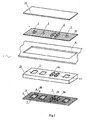
- a control unit 1 comprising lightning information segments 2 for marking and illuminated capacitive switches 3 is integrated in a front panel 4 of an appliance or apparatus which can be a household appliance, a computer control system, a medical device or any other device or machine controlled by a human.
- the basis of the control unit 1 is a printed circuit board 5. Its upper side is provided with fields 6 of capacitive switches 3 which are substantially electrically conductive surfaces 6b, and with fields 6a of the segments 2 of a seven-segment display. Fields 6, 6a are coated with a white protective layer 8, 8a in order to achieve better reflection of the light provided by a side LED 7 arranged at an edge of the fields 6, 6a. All remaining surfaces not falling within the fields 6, 6a are coated with a black protective layer 9 that reduces penetration of the light into individual fields 6, 6a.
- the upper plane of the frame 10 is provided with openings 11, 11a, the positions of which coincide with respective positions of individual fields 6, 6a on the printed circuit board 5.
- light guides 14 that provide for an even illumination of capacitive switches 3 or lightning segments 2.
- a graphic foil 12 is arranged, on which foil individual transparent graphical symbols are arranged, the positions of which coincide with respective positions of the openings 11, 11a for the light guide 14 in the support frame 10 underneath the graphic foil 12 which may be additionally protected by a board 13.
- a variant without a graphic foil 12 is also possible, wherein the graphical symbols are preferably formed on the lower side of the board 13 by way of printing.
- Figure 2 shows a cross-section of the segment 2 of the seven-segment display.
- Said segment is illuminated by the side LED 7.
- the LED 7 is arranged on the printed circuit board 5 which forms a bottom limit of a cavity 19 of said segment 2.
- Said cavity is limited at its upper side by the graphic foil 12.
- the light of individual segments 2 is separated by means of the support frame 10.
- At one side the frame limits the cavity 19 by a plane 20, and at the other side the frame is embodied in a way to cover the upper side of the LED 7 by a limiter 21.
- the cavity 19 may be provided with a lightning guide 14 made of a special heat or UV curable transparent material. This material is poured into individual openings 11a of the support frame 10, said openings simultaneously also representing the openings of the cavities 19 of the segments 2 and coinciding with the arrangement of individual segments on the printed circuit board 5.
- Figure 3 shows an illuminated capacitive switch 3 in a cross-section, where the light guide 14 is formed of a special material that is curable by means of temperature of UV light. This material is poured into cavities 15. The bottom of the cavity 15 is coated with the electrically conductive layer 6b of a sensor of the capacitive switch 3, said layer being formed in the shape of a mesh as shown in Figure 4 . This layer is covered with the protective layer 8. Said protective layer 8 which is preferably a white colour must have such thickness and viscosity to preserve the configuration of recesses 18 of the electrically conductive layer 6b, which cavities are then filled with a liquid material.
- Said protective layer 8 which is preferably a white colour must have such thickness and viscosity to preserve the configuration of recesses 18 of the electrically conductive layer 6b, which cavities are then filled with a liquid material.
- Projections 17 of the light guide 14 act as lenses and form an uneven surface and together with the white protective layer 8 of the printed circuit represent a light scattering means (refractor) or a light reflecting means (reflector).
- the luminous flux emitted by the LED 7 is thus evenly spread in the cavity 15 and evenly illuminates a touch surface of a key from underneath.
- the black protective layer 9 between the sensors of the switches reduces the light from penetrating into adjacent capacitive switches.
- the material used for light guides can be for instance heat curable Protavic PNU46202 or UV curable GE680.
- the disclosed invention may be applied for other applications as well, for instance in a stepping switch.
- Individual capacitive switches can be logically electrically connected into a set for a functional step-wise setting of values.
Landscapes
- Physics & Mathematics (AREA)
- General Physics & Mathematics (AREA)
- Optics & Photonics (AREA)
- Engineering & Computer Science (AREA)
- Theoretical Computer Science (AREA)
- Illuminated Signs And Luminous Advertising (AREA)
- Switches That Are Operated By Magnetic Or Electric Fields (AREA)
- Infusion, Injection, And Reservoir Apparatuses (AREA)
Applications Claiming Priority (1)
| Application Number | Priority Date | Filing Date | Title |
|---|---|---|---|
| SI201200350A SI24242A (sl) | 2012-11-20 | 2012-11-20 | Upravljalna enota naprave |
Publications (2)
| Publication Number | Publication Date |
|---|---|
| EP2733414A2 true EP2733414A2 (de) | 2014-05-21 |
| EP2733414A3 EP2733414A3 (de) | 2017-10-18 |
Family
ID=49766827
Family Applications (1)
| Application Number | Title | Priority Date | Filing Date |
|---|---|---|---|
| EP13005376.2A Withdrawn EP2733414A3 (de) | 2012-11-20 | 2013-11-15 | Bedienungsfeld eines Geräts |
Country Status (3)
| Country | Link |
|---|---|
| EP (1) | EP2733414A3 (de) |
| RU (1) | RU2635828C2 (de) |
| SI (1) | SI24242A (de) |
Cited By (5)
| Publication number | Priority date | Publication date | Assignee | Title |
|---|---|---|---|---|
| EP2789902A2 (de) * | 2013-04-09 | 2014-10-15 | Whirlpool Corporation | Geräteanzeigen mit modularen Lichtleitern und Verfahren zur Montage davon |
| CN111426906A (zh) * | 2020-03-12 | 2020-07-17 | 广西电网有限责任公司电力科学研究院 | 一种应用于配电网实境试验平台的网架结构 |
| CN111527003A (zh) * | 2017-12-15 | 2020-08-11 | 利萨·德雷克塞迈尔有限责任公司 | 具有集成的操作元件的线形照明装置 |
| US20240337402A1 (en) * | 2021-06-21 | 2024-10-10 | Ademco Inc. | Wall-mounted control device |
| US20250110268A1 (en) * | 2023-09-28 | 2025-04-03 | Chicony Power Technology Co., Ltd. | Light-emitting module |
Citations (2)
| Publication number | Priority date | Publication date | Assignee | Title |
|---|---|---|---|---|
| WO2007138294A1 (en) | 2006-05-26 | 2007-12-06 | Design Led Products Limited | A composite light guiding device |
| GB2459888A (en) | 2008-05-09 | 2009-11-11 | Design Led Products Ltd | Capacitive switch |
Family Cites Families (5)
| Publication number | Priority date | Publication date | Assignee | Title |
|---|---|---|---|---|
| DE10236718A1 (de) * | 2002-08-06 | 2004-02-12 | E.G.O. Control Systems Gmbh & Co. Kg | Elektrohaushaltsgerät mit Anzeigeeinrichtung |
| DE102005023440A1 (de) * | 2005-05-20 | 2006-11-30 | BSH Bosch und Siemens Hausgeräte GmbH | Anzeige- und/oder Bedienungspaneel |
| US7845826B2 (en) * | 2008-01-15 | 2010-12-07 | Skc Haas Display Films Co., Ltd. | Multilayered integrated backlight illumination assembly |
| DE102009011678A1 (de) * | 2009-02-23 | 2010-08-26 | E.G.O. Elektro-Gerätebau GmbH | Bedieneinrichtung für ein Elektro-Hausgerät und Bedienverfahren |
| DE102009033538A1 (de) * | 2009-07-09 | 2011-01-13 | E.G.O. Elektro-Gerätebau GmbH | Bedieneinrichtung für ein Elektrogerät |
-
2012
- 2012-11-20 SI SI201200350A patent/SI24242A/sl active IP Right Grant
-
2013
- 2013-11-15 EP EP13005376.2A patent/EP2733414A3/de not_active Withdrawn
- 2013-11-19 RU RU2013151503A patent/RU2635828C2/ru not_active IP Right Cessation
Patent Citations (2)
| Publication number | Priority date | Publication date | Assignee | Title |
|---|---|---|---|---|
| WO2007138294A1 (en) | 2006-05-26 | 2007-12-06 | Design Led Products Limited | A composite light guiding device |
| GB2459888A (en) | 2008-05-09 | 2009-11-11 | Design Led Products Ltd | Capacitive switch |
Cited By (7)
| Publication number | Priority date | Publication date | Assignee | Title |
|---|---|---|---|---|
| EP2789902A2 (de) * | 2013-04-09 | 2014-10-15 | Whirlpool Corporation | Geräteanzeigen mit modularen Lichtleitern und Verfahren zur Montage davon |
| CN111527003A (zh) * | 2017-12-15 | 2020-08-11 | 利萨·德雷克塞迈尔有限责任公司 | 具有集成的操作元件的线形照明装置 |
| CN111527003B (zh) * | 2017-12-15 | 2024-04-30 | 利萨·德雷克塞迈尔有限责任公司 | 具有集成的操作元件的线形照明装置 |
| CN111426906A (zh) * | 2020-03-12 | 2020-07-17 | 广西电网有限责任公司电力科学研究院 | 一种应用于配电网实境试验平台的网架结构 |
| US20240337402A1 (en) * | 2021-06-21 | 2024-10-10 | Ademco Inc. | Wall-mounted control device |
| US20250110268A1 (en) * | 2023-09-28 | 2025-04-03 | Chicony Power Technology Co., Ltd. | Light-emitting module |
| US12585061B2 (en) * | 2023-09-28 | 2026-03-24 | Chicony Power Technology Co., Ltd. | Light-emitting module |
Also Published As
| Publication number | Publication date |
|---|---|
| RU2013151503A (ru) | 2015-05-27 |
| SI24242A (sl) | 2014-05-30 |
| EP2733414A3 (de) | 2017-10-18 |
| RU2635828C2 (ru) | 2017-11-16 |
Similar Documents
| Publication | Publication Date | Title |
|---|---|---|
| EP2733414A2 (de) | Bedienungsfeld eines Geräts | |
| CN106461883B (zh) | 用于制造电子产品的方法、相关的配置以及产品 | |
| KR101072209B1 (ko) | 집적 로우 프로파일 디스플레이 | |
| EP1376872B1 (de) | Beleuchtungseinrichtung für Schaltflächen | |
| KR20090048394A (ko) | 키 시트 및 그것을 구비한 키 유닛 및 키 시트의 제조 방법 | |
| CN105850230A (zh) | 用于电子装置的照明指示器结构 | |
| JPWO2007123202A1 (ja) | 表示装置およびその製造方法、パターン表示方法、ならびにブラインド装置およびブラインド方法 | |
| CN103423961A (zh) | 触控面板组件及冰箱 | |
| JP4971427B2 (ja) | 電気デバイスの照明 | |
| US20100170775A1 (en) | Keypad assembly and manufacturing method thereof | |
| JP2019061787A (ja) | 表示装置及び液晶表示装置 | |
| EP1903284B1 (de) | Vorrichtung für ein Haushaltsgerät und Verwendung der Vorrichtung | |
| CN105874276B (zh) | 家用电器操作装置 | |
| KR101330937B1 (ko) | 이동단말기의 백라이팅 구조물 제조방법, 이동단말기의백라이팅 구조물 및 백라이팅 구조물 구비 이동단말기 | |
| EP2678605B1 (de) | Flache beleuchtungsanordnung mit einer integrierten elektrischen schaltung | |
| CN218471000U (zh) | 用于家用电器的显示装置、人机交互设备和家用电器 | |
| CN104444661A (zh) | 新型电梯按钮 | |
| KR101042919B1 (ko) | 휴대폰용 키패드 조립체 | |
| CN206003672U (zh) | 导光薄膜开关 | |
| CN202839411U (zh) | 发光键盘 | |
| US20150204535A1 (en) | Electric home appliance | |
| JP7269985B2 (ja) | 発光モジュール、発光モジュールの製造方法及び電子装置 | |
| CN103090316A (zh) | 触摸按键导光结构 | |
| KR200267261Y1 (ko) | 발광 다이오드를 이용한 광발산 구조체 | |
| RU183112U1 (ru) | Клавиатура с подсветкой клавиш |
Legal Events
| Date | Code | Title | Description |
|---|---|---|---|
| PUAI | Public reference made under article 153(3) epc to a published international application that has entered the european phase |
Free format text: ORIGINAL CODE: 0009012 |
|
| 17P | Request for examination filed |
Effective date: 20131115 |
|
| AK | Designated contracting states |
Kind code of ref document: A2 Designated state(s): AL AT BE BG CH CY CZ DE DK EE ES FI FR GB GR HR HU IE IS IT LI LT LU LV MC MK MT NL NO PL PT RO RS SE SI SK SM TR |
|
| AX | Request for extension of the european patent |
Extension state: BA ME |
|
| PUAL | Search report despatched |
Free format text: ORIGINAL CODE: 0009013 |
|
| AK | Designated contracting states |
Kind code of ref document: A3 Designated state(s): AL AT BE BG CH CY CZ DE DK EE ES FI FR GB GR HR HU IE IS IT LI LT LU LV MC MK MT NL NO PL PT RO RS SE SI SK SM TR |
|
| AX | Request for extension of the european patent |
Extension state: BA ME |
|
| RIC1 | Information provided on ipc code assigned before grant |
Ipc: F21V 8/00 20060101AFI20170914BHEP Ipc: G02B 6/00 20060101ALI20170914BHEP Ipc: G09F 13/18 20060101ALI20170914BHEP |
|
| STAA | Information on the status of an ep patent application or granted ep patent |
Free format text: STATUS: THE APPLICATION IS DEEMED TO BE WITHDRAWN |
|
| 18D | Application deemed to be withdrawn |
Effective date: 20180419 |