EP2733425A1 - Turbomotor und gestuftes Verbrennungssystem eines Turbomotors - Google Patents
Turbomotor und gestuftes Verbrennungssystem eines Turbomotors Download PDFInfo
- Publication number
- EP2733425A1 EP2733425A1 EP13192456.5A EP13192456A EP2733425A1 EP 2733425 A1 EP2733425 A1 EP 2733425A1 EP 13192456 A EP13192456 A EP 13192456A EP 2733425 A1 EP2733425 A1 EP 2733425A1
- Authority
- EP
- European Patent Office
- Prior art keywords
- combustor
- fuel
- injectors
- head end
- transition piece
- Prior art date
- Legal status (The legal status is an assumption and is not a legal conclusion. Google has not performed a legal analysis and makes no representation as to the accuracy of the status listed.)
- Granted
Links
Images


Classifications
-
- F—MECHANICAL ENGINEERING; LIGHTING; HEATING; WEAPONS; BLASTING
- F02—COMBUSTION ENGINES; HOT-GAS OR COMBUSTION-PRODUCT ENGINE PLANTS
- F02C—GAS-TURBINE PLANTS; AIR INTAKES FOR JET-PROPULSION PLANTS; CONTROLLING FUEL SUPPLY IN AIR-BREATHING JET-PROPULSION PLANTS
- F02C3/00—Gas-turbine plants characterised by the use of combustion products as the working fluid
- F02C3/20—Gas-turbine plants characterised by the use of combustion products as the working fluid using a special fuel, oxidant, or dilution fluid to generate the combustion products
- F02C3/22—Gas-turbine plants characterised by the use of combustion products as the working fluid using a special fuel, oxidant, or dilution fluid to generate the combustion products the fuel or oxidant being gaseous at standard temperature and pressure
-
- F—MECHANICAL ENGINEERING; LIGHTING; HEATING; WEAPONS; BLASTING
- F23—COMBUSTION APPARATUS; COMBUSTION PROCESSES
- F23R—GENERATING COMBUSTION PRODUCTS OF HIGH PRESSURE OR HIGH VELOCITY, e.g. GAS-TURBINE COMBUSTION CHAMBERS
- F23R3/00—Continuous combustion chambers using liquid or gaseous fuel
- F23R3/28—Continuous combustion chambers using liquid or gaseous fuel characterised by the fuel supply
- F23R3/34—Feeding into different combustion zones
-
- F—MECHANICAL ENGINEERING; LIGHTING; HEATING; WEAPONS; BLASTING
- F02—COMBUSTION ENGINES; HOT-GAS OR COMBUSTION-PRODUCT ENGINE PLANTS
- F02C—GAS-TURBINE PLANTS; AIR INTAKES FOR JET-PROPULSION PLANTS; CONTROLLING FUEL SUPPLY IN AIR-BREATHING JET-PROPULSION PLANTS
- F02C7/00—Features, components parts, details or accessories, not provided for in, or of interest apart form groups F02C1/00 - F02C6/00; Air intakes for jet-propulsion plants
- F02C7/22—Fuel supply systems
- F02C7/228—Dividing fuel between various burners
-
- F—MECHANICAL ENGINEERING; LIGHTING; HEATING; WEAPONS; BLASTING
- F23—COMBUSTION APPARATUS; COMBUSTION PROCESSES
- F23R—GENERATING COMBUSTION PRODUCTS OF HIGH PRESSURE OR HIGH VELOCITY, e.g. GAS-TURBINE COMBUSTION CHAMBERS
- F23R3/00—Continuous combustion chambers using liquid or gaseous fuel
- F23R3/28—Continuous combustion chambers using liquid or gaseous fuel characterised by the fuel supply
- F23R3/36—Supply of different fuels
Definitions
- the subject matter disclosed herein relates to a turbomachine and a staged combustion system of a turbomachine.
- a turbomachine may include a combustor, a turbine section and a transition piece.
- the combustor is formed to define an interior in which fuel and air are combustible to produce a working fluid.
- the turbine section is disposed downstream from the combustor and is formed to be receptive of at least the working fluid produced in the combustor for power generation operations.
- the transition piece is fluidly interposed between the combustor and the turbine section. As such, the transition piece is configured to transport the working fluid from the combustor 20 the turbine section.
- turbomachines can often be expensive, insufficiently volatile for a given turbomachine operation or excessively volatile for a given turbomachine operation. Generally, however, turbomachines lack fuel flexibility that would alleviate these concerns.
- a turbomachine includes a combustor in which fuel is combustible to produce a working fluid, a turbine section, which is receptive of the working fluid for power generation operations, a transition piece in which additional fuel is combustible, the transition piece being disposed to transport the working fluid from the combustor to the turbine section and a staged combustion system coupled to the combustor and the transition piece.
- the staged combustion system is configured to blend components of the fuel and the additional fuel in multiple modes.
- a staged combustion system of a turbomachine includes a combustor in which fuel is combustible to produce a working fluid, a turbine section, which is receptive of the working fluid for power generation operations and a transition piece in which additional fuel is combustible.
- the transition piece is disposable to transport the working fluid from the combustor to the turbine section and includes head end injectors disposable to deliver fuel blended in multiple modes to a head end of the combustor and axially staged injectors disposable to deliver additional fuel blended in multiple modes to downstream sections of the combustor and the transition piece.
- a method of operating a turbomachine includes combusting fuel in a combustor to produce a working fluid, transporting the working fluid from the combustor and through a transition piece, combusting additional fuel in the transition piece and blending components of the fuel and the additional fuel in multiple modes.
- a turbomachine and an axially staged combustion system of a turbomachine are provided. This will allow for increasingly fuel flexible turbomachine operations, turbomachine operations with a relatively wide Wobbie index, increased flash back margins and increased control of thermal acoustics.
- the turbomachine includes a combustor 20, a turbine section 30, a transition piece 40 and an axially staged combustion system 50.
- the combustor 20 includes a liner 21 and a flow sleeve 22.
- the liner 21 is formed to define an interior 23 in which fuel and air are combustible to produce a working fluid.
- the flow sleeve 22 is disposed around the liner 21 to define a first air flow pathway 24.
- the turbine section 30 is disposed downstream from the combustor 20 and is formed to be receptive of at least the working fluid produced in the combustor 20 for power generation operations.
- the transition piece 40 is fluidly interposed between downstream sections 25 of the combustor 20 and a forward stage 31 of the turbine section 30. As such, the transition piece 40 is configured to transport the working fluid from the combustor 20 to the turbine section 30.
- the transition piece 40 includes a liner 41 and an impingement sleeve 42.
- the liner 41 is formed to define an interior 43 through which the working fluid is transported from the combustor 20 to the turbine section 30.
- the impingement sleeve 42 is disposed around the liner 41 to define a second air flow pathway 44, which may be communicative with the first air flow pathway 24.
- the transition piece 40 includes a forward end 45 that is connectible to the combustor 20 and is generally aligned with a predominant direction of a flowpath defined through the combustor 20, an aft end 46 that is connectible to the turbine section 30 and generally aligned with a predominant direction of a flowpath through the turbine section 30 and a central portion 47.
- the central portion 47 extends from the forward end 45 to the aft end 46.
- the forward end 45 may be generally annular in shape in correspondence with a similar shape of the downstream sections 25 of the combustor 20.
- the aft end 46 may be elongate in a circumferential dimension relative to a rotor of the turbomachine 10.
- the central portion 47 is formed such that the annular shape of the forward end 45 gradually changes to the elongate shape of the aft end 46.
- the central portion 47 may include a radial curvature relative to the rotor such that the aft end 46 is disposed radially inwardly from the forward end 45.
- the flowpath through the combustor 20 may be offset from the flowpath through the turbine section 30.
- the curved formation of the transition piece 40 permits fluid flow from the combustor 20 to the turbine section 30 despite the offset.
- the turbomachine 10 may be configured to perform axially staged injection or late lean injection (LLI) of fuel and/or air in the downstream sections 25 of the combustor 20 and the transition piece 40.
- LLI late lean injection
- additional fuel may be received by and combustible within the downstream sections 25 of the combustor 20 and the interior 43 of the transition piece 40.
- axially staged injection or LLI techniques a more complete combustion of fuel and additional fuel may be achieved as compared to what would otherwise be possible.
- pollutant e.g., oxides of nitrogen
- the axially staged combustion system 50 may be coupled to one or both of the combustor 20 and the transition piece 40.
- the axially staged combustion system 50 is configured to blend components of both the fuel and the additional fuel in multiple modes of turbomachine 10 operation such that the fuel and the additional fuel can be advantageously injected into the combustor 20 and the transition piece 30.
- the axially staged combustion system 50 includes head end injectors 51 and axially staged injectors 52.
- the head end injectors 51 are disposable to deliver the fuel to a head end 26 of the combustor 20, which is defined upstream from the downstream sections 25 of the combustor 20.
- the head end 26 may include an end plate 260 to which the head end injectors 51 are attachable in various configurations.
- the axially staged injectors 52 are disposable to deliver the additional fuel to the downstream sections 25 of the combustor 20 and to the transition piece 30.
- the axially staged injectors 52 may be arranged in at least a first stage 520 and a second stage 521, which is disposed downstream from the first stage 520. Three or more axially staged injectors 52 may be disposed at the first stage 520 and may be arranged about the downstream sections 25 of the combustor 20 in a substantially even circumferential distribution.
- a first fuel manifold 53 may be provided to supply the axially staged injectors 52 of the first stage 520 with the additional fuel.
- three or more axially staged injectors 52 may be disposed at the second stage 521 and may be arranged about the transition piece 30 in a substantially even circumferential distribution.
- a second fuel manifold 54 may be provided to supply the axially staged injectors 52 of the second stage 521 with the additional fuel. As shown in FIG. 2 , the second fuel manifold 54 and the axially staged injectors 52 of the second stage 521 may be disposed at an axial location just forward from the beginning of the radial curvature of the transition piece 30.
- the first and second fuel manifolds 53 and 54 may be coupled to one another and to fuel circuits, which will be described below and which may also be coupled to the head end injectors 51.
- the fuel circuits may be configured to access various types of fuels and to provide the various types of the fuels to the head end injectors 51 and to the axially staged injectors 52.
- the fuels circuit may be configured to provide various blends of the fuel to the head end injectors 51 and to provide various blends of the additional fuel to the axially staged injectors.
- the various blends of the additional fuel supplied to the axially staged injectors 52 of the first stage 520 may be similar to or different from the various blends of the additional fuel supplied to the axially staged injectors 52 of the second stage 521.
- a determination of the respective blend(s) of the fuel and the additional fuel to be supplied to the head end injectors 51 and the axially staged injectors 52 may be made in accordance with the one of the multiple modes of turbomachine 10 operation currently in effect.
- Each one of the multiple modes of turbomachine 10 operation can be employed interchangeably with the others or in accordance with pre-defined schedules and/or specific turbomachine 10 loads.
- the ability of the turbomachine 10 to operate in the multiple modes of turbomachine 10 operation provides for fuel flexibility, operations at relatively wide Wobbie indices and increased flash back margin.
- the multiple modes comprise one or more of at least first through fourth modes.
- the head end injectors 51 deliver natural gas as the fuel to the head end 26 of the combustor 20 and the axially staged injectors 52 deliver syngas or a low heating value gas as the additional fuel to the downstream sections 25 of the combustor 20 and the transition piece 30.
- the head end injectors 51 deliver natural gas and syngas as the fuel to the head end 26 of the combustor 20 and the axially staged injectors 52 deliver a low heating value gas as the additional fuel to the downstream sections 25 of the combustor 20 and the transition piece 30.
- the head end injectors 51 deliver a low heating value gas as the fuel to the head end 26 of the combustor 20 and the axially staged injectors 52 deliver natural gas or a low heating value gas as the additional fuel to the downstream sections 25 of the combustor 20 and the transition piece 30.
- the head end injectors 51 deliver a first blend of natural gas and a low heating value gas (e.g., a blend level of about 10% - 50% of natural gas) as the fuel to the head end 26 of the combustor 20 and the axially staged injectors 52 deliver a second blend of natural gas and a low heating value gas (e.g., a blend level of about 10% - 50% of natural gas) as the additional fuel to the downstream sections 25 of the combustor 20 and the transition piece 30.
- a low heating value gas e.g., a blend level of about 10% - 50% of natural gas
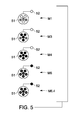
- gas fuel 1 may be purged, provided for combustion via the head end injectors 51 in primary, secondary or tertiary arrangements and/or provided for combustion via the axially staged injectors 52.
- Gas fuel 1 may include one or more types of high heating value fuel, such as natural gas or methane.
- the primary, secondary and tertiary arrangements refer to sets of the fuel nozzles of the head end fuel injectors 51 that are activated at one time and to the level of activation of the fuel nozzles (i.e., a center burner may be activated, outer annulus burners may be activated or the center burner and the outer annulus burners may be activated).
- gas fuel 2 may be purged and/or provided for combustion via the head end injectors 51 in primary A or primary B arrangements.
- Gas fuel 2 may include one or more types of low heating value fuel, such as syngas.
- the primary A and primary B arrangements refer to sets of the fuel nozzles of the head end fuel inj ectors 51 that are activated at one time and to the level of activation of the fuel nozzles (i.e., a center burner may be activated, outer annulus burners may be activated or the center burner and the outer annulus burners may be activated).
- the turbomachine 10 may be operated in modes M1, M3, M4, M6 and M6.4.
- Modes M2 and M5 are not shown but can be understood as being intermediate modes where modes M1 and M3 overlap and modes M4 and M6 overlap, respectively.
- gas fuel 1 is provided for combustion (in, for example, combustor 20) via the head end injectors 51 in the secondary arrangement.
- the secondary arrangement includes activation of the center burner in the central fuel nozzle and two outer fuel nozzles of the head end injectors 51.
- gas fuel 1 is provided for combustion via the head end injectors 51 in the secondary arrangement and the gas fuel 2 is provided for combustion via the head end injectors 51 in the primary A arrangement.
- the primary A arrangement includes activation of the outer annulus burners of the central fuel nozzle and activation of the center burner and the outer annulus burners of the remaining three outer fuel nozzles of the head end injectors 51.
- gas fuel 1 is provided for combustion via the head end injectors 51 in the secondary arrangement and the gas fuel 2 is provided for combustion via the head end injectors 51 in the primary A arrangement and in the primary B arrangement.
- the primary B arrangement includes activation of the center burner and the outer annulus burners of each of the fuel nozzles of the head end injectors 51.
- gas fuels 1 and 2 are provided for combustion via the head end injectors 51 in the tertiary, primary A and primary B arrangements while gas fuel 1 is further provided to the axially staged injectors 52.
- the tertiary, primary A and primary B arrangements include activation of the outer annulus burners of each of the fuel nozzles of the head end injectors 51.
- gas fuels 1 and 2 are provided for combustion via the head end injectors 51 in the primary, secondary, tertiary, primary A and primary B arrangements while gas fuel 1 is further provided to the axially staged injectors 52.
- the primary, secondary, tertiary, primary A and primary B arrangements include activation of the outer annulus burners of each of the fuel nozzles and the additional activation of the center burner of the center fuel nozzle of the head end injectors 51.
- the turbomachine 10 may proceed from the M6 mode to the M4 mode and from the M4 mode to the M3 mode.
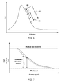
- FIG. 6 a graphical depiction of an improvement in the Wobbie index operation window afforded by the operation of the turbomachine 10 as described above is illustrated.
- the operational temperatures of the turbomachine 10 increase sharply, reach a high temperature and then reduce nearly as sharply.
- a low heating value fuel can be employed for combustion during the first, relatively high temperature window 60 whereas a high heating value fuel can be employed during the second, relatively cool temperature window 61.
- turbomachine 10 The capability of the turbomachine 10 described above to conduct fuel flexible operations makes it possible for the turbomachine 10 to be effectively operable along the wide temperature window 62, which extends from the onset of the first, relatively high temperature window 60 to the termination of the second, relatively cool temperature window 61.
- FIG. 7 is a graphical depiction of an improvement in flameholding capabilities afforded by the operation of the turbomachine 10 as described above is illustrated.
- an operational region between a high flashback risk and a natural gas baseline can be seen between the two dotted lines.
- the respective areas between the lower dotted line and the dashed and solid lines represent flashback margins associated with fuel types having given percentages of a high heating value fuel, such as 10% and 20% natural gas, respectively.
- the size and shape of these areas indicate that the flashback margin increases, for the given natural gas percentages, as a primary split percentage decreases and a burn off time increases. Indeed, the effect is more pronounced as the natural gas percentage decreases.
- the ability of the turbomachine 10 to employ fuel flexibility and to thereby use a decreased natural gas percentage in a fuel type leads to a decreased risk of flashback or flameholding.
Landscapes
- Engineering & Computer Science (AREA)
- Chemical & Material Sciences (AREA)
- Combustion & Propulsion (AREA)
- Mechanical Engineering (AREA)
- General Engineering & Computer Science (AREA)
- Gas Burners (AREA)
Applications Claiming Priority (1)
| Application Number | Priority Date | Filing Date | Title |
|---|---|---|---|
| US13/676,683 US9291098B2 (en) | 2012-11-14 | 2012-11-14 | Turbomachine and staged combustion system of a turbomachine |
Publications (2)
| Publication Number | Publication Date |
|---|---|
| EP2733425A1 true EP2733425A1 (de) | 2014-05-21 |
| EP2733425B1 EP2733425B1 (de) | 2019-07-17 |
Family
ID=49596077
Family Applications (1)
| Application Number | Title | Priority Date | Filing Date |
|---|---|---|---|
| EP13192456.5A Active EP2733425B1 (de) | 2012-11-14 | 2013-11-12 | Turbomotor und gestuftes Verbrennungssystem eines Turbomotors |
Country Status (4)
| Country | Link |
|---|---|
| US (1) | US9291098B2 (de) |
| EP (1) | EP2733425B1 (de) |
| JP (1) | JP6325235B2 (de) |
| CN (1) | CN203847250U (de) |
Cited By (2)
| Publication number | Priority date | Publication date | Assignee | Title |
|---|---|---|---|---|
| EP2902708A4 (de) * | 2014-06-12 | 2015-10-07 | Kawasaki Heavy Ind Ltd | Gasturbinenbrennkammer für mehrere brennstoffe |
| EP4174379A1 (de) * | 2021-10-28 | 2023-05-03 | General Electric Company | Verfahren zum betrieb einer turbomaschinenbrennkammer mit wasserstoff |
Families Citing this family (17)
| Publication number | Priority date | Publication date | Assignee | Title |
|---|---|---|---|---|
| JP5458121B2 (ja) * | 2012-01-27 | 2014-04-02 | 株式会社日立製作所 | ガスタービン燃焼器およびガスタービン燃焼器の運転方法 |
| US9551492B2 (en) * | 2012-11-30 | 2017-01-24 | General Electric Company | Gas turbine engine system and an associated method thereof |
| US20150107255A1 (en) * | 2013-10-18 | 2015-04-23 | General Electric Company | Turbomachine combustor having an externally fueled late lean injection (lli) system |
| WO2015060902A1 (en) * | 2013-10-25 | 2015-04-30 | United Technologies Corporation | Spherical ball bearing housing |
| US9689574B2 (en) * | 2014-02-03 | 2017-06-27 | General Electric Company | System and method for reducing modal coupling of combustion dynamics |
| EP2910751B1 (de) * | 2014-02-19 | 2016-12-21 | United Technologies Corporation | Brennstoffverteiler für einen Gasturbinenmotor |
| US10012387B2 (en) * | 2014-12-05 | 2018-07-03 | General Electric Company | Fuel supply system for a gas turbine engine |
| EP3625504B1 (de) * | 2017-05-16 | 2021-11-24 | Siemens Energy Global GmbH & Co. KG | Binäres kraftstoffstufungsschema für verbesserte teillastbetriebsemissionen in einer turbinenverbrennung mit magerem gasvorgemisch |
| US11187415B2 (en) | 2017-12-11 | 2021-11-30 | General Electric Company | Fuel injection assemblies for axial fuel staging in gas turbine combustors |
| US11137144B2 (en) | 2017-12-11 | 2021-10-05 | General Electric Company | Axial fuel staging system for gas turbine combustors |
| US10816203B2 (en) | 2017-12-11 | 2020-10-27 | General Electric Company | Thimble assemblies for introducing a cross-flow into a secondary combustion zone |
| US11156162B2 (en) * | 2018-05-23 | 2021-10-26 | General Electric Company | Fluid manifold damper for gas turbine engine |
| EP3594475A1 (de) * | 2018-07-10 | 2020-01-15 | Siemens Aktiengesellschaft | Verfahren zum betreiben einer gasturbinenanlage mit gasförmigem brennstoff |
| CN109489071B (zh) * | 2018-11-28 | 2023-09-12 | 中国华能集团有限公司 | 一种低NOx排放的燃烧室、燃气轮机系统、燃气轮机系统的启动方法及负荷调节方法 |
| CN114791104B (zh) * | 2021-01-25 | 2026-03-10 | 李华玉 | 双燃料高温热源与双燃料燃气轮机装置 |
| JP2023158415A (ja) * | 2022-04-18 | 2023-10-30 | 三菱重工業株式会社 | 燃焼器、及びこれを備えるガスタービン |
| US12590556B1 (en) | 2024-10-01 | 2026-03-31 | General Electric Company | Gas turbine engine, fuel nozzle assembly, and method |
Citations (3)
| Publication number | Priority date | Publication date | Assignee | Title |
|---|---|---|---|---|
| EP1985927A2 (de) * | 2007-04-27 | 2008-10-29 | General Electric Company | Verfahren und Systeme zur Reduktion von NOx-Emissionen in Verbrennungssystemen |
| EP2204563A2 (de) * | 2008-12-31 | 2010-07-07 | General Electric Company | Betreiben einer Turbine bei Grundlast mit kaltem Brennstoff mit Hardware zur Verbrennung von erhitztem Brennstoff |
| EP2206961A2 (de) * | 2009-01-07 | 2010-07-14 | General Electric Company | Gasturbinentriebwerk mit später Magereinspritzung und einstellbarer Luftaufteilung |
Family Cites Families (23)
| Publication number | Priority date | Publication date | Assignee | Title |
|---|---|---|---|---|
| JPS6152523A (ja) | 1984-08-22 | 1986-03-15 | Hitachi Ltd | ガスタ−ビン燃焼器 |
| JPS6361725A (ja) | 1986-09-01 | 1988-03-17 | Hitachi Ltd | ガスタ−ビン制御方式 |
| ZA894283B (en) | 1988-06-08 | 1990-09-26 | Velino Ventures Inc | Combustion of carbon containing meterials in a furnace |
| JP2631892B2 (ja) | 1989-03-27 | 1997-07-16 | 株式会社日本ケミカル・プラント・コンサルタント | 加熱装置 |
| US5020451A (en) | 1989-10-05 | 1991-06-04 | Ishikawajima-Harima Heavy Industries Co., Ltd. | Fluidized-bed combustion furnace |
| JPH0814369B2 (ja) | 1991-03-26 | 1996-02-14 | 川崎重工業株式会社 | 石炭燃焼炉の燃焼制御装置 |
| JPH0781701B2 (ja) | 1991-04-05 | 1995-09-06 | 川崎重工業株式会社 | 石炭燃焼炉の灰中未燃分推定装置 |
| US5327726A (en) | 1992-05-22 | 1994-07-12 | Foster Wheeler Energy Corporation | Staged furnaces for firing coal pyrolysis gas and char |
| US5491970A (en) * | 1994-06-10 | 1996-02-20 | General Electric Co. | Method for staging fuel in a turbine between diffusion and premixed operations |
| US6193500B1 (en) | 1998-02-26 | 2001-02-27 | Robert Bradt | Method and apparatus for controlling gasoline vapor emissions |
| US6289851B1 (en) | 2000-10-18 | 2001-09-18 | Institute Of Gas Technology | Compact low-nox high-efficiency heating apparatus |
| DE60238470D1 (de) | 2001-02-27 | 2011-01-13 | Yantai Longyuan Power Tech Co | Plasmazünder mit zusammengesetzter kathode |
| AU2005229668B2 (en) | 2004-11-04 | 2008-03-06 | Babcock-Hitachi K.K. | Overfiring air port, method for manufacturing air port, boiler, boiler facility, method for operating boiler facility and method for improving boiler facility |
| US7631499B2 (en) | 2006-08-03 | 2009-12-15 | Siemens Energy, Inc. | Axially staged combustion system for a gas turbine engine |
| US7690192B2 (en) | 2007-04-17 | 2010-04-06 | Pratt & Whitney Rocketdyne, Inc. | Compact, high performance swirl combustion rocket engine |
| US8701383B2 (en) | 2009-01-07 | 2014-04-22 | General Electric Company | Late lean injection system configuration |
| US8707707B2 (en) | 2009-01-07 | 2014-04-29 | General Electric Company | Late lean injection fuel staging configurations |
| US8683808B2 (en) | 2009-01-07 | 2014-04-01 | General Electric Company | Late lean injection control strategy |
| US8701382B2 (en) | 2009-01-07 | 2014-04-22 | General Electric Company | Late lean injection with expanded fuel flexibility |
| US8701418B2 (en) | 2009-01-07 | 2014-04-22 | General Electric Company | Late lean injection for fuel flexibility |
| JP4934696B2 (ja) * | 2009-03-26 | 2012-05-16 | 株式会社日立製作所 | バーナ及び燃焼器 |
| US8545215B2 (en) | 2010-05-17 | 2013-10-01 | General Electric Company | Late lean injection injector |
| US8613197B2 (en) * | 2010-08-05 | 2013-12-24 | General Electric Company | Turbine combustor with fuel nozzles having inner and outer fuel circuits |
-
2012
- 2012-11-14 US US13/676,683 patent/US9291098B2/en active Active
-
2013
- 2013-11-11 JP JP2013232639A patent/JP6325235B2/ja active Active
- 2013-11-12 EP EP13192456.5A patent/EP2733425B1/de active Active
- 2013-11-14 CN CN201320717464.5U patent/CN203847250U/zh not_active Expired - Lifetime
Patent Citations (3)
| Publication number | Priority date | Publication date | Assignee | Title |
|---|---|---|---|---|
| EP1985927A2 (de) * | 2007-04-27 | 2008-10-29 | General Electric Company | Verfahren und Systeme zur Reduktion von NOx-Emissionen in Verbrennungssystemen |
| EP2204563A2 (de) * | 2008-12-31 | 2010-07-07 | General Electric Company | Betreiben einer Turbine bei Grundlast mit kaltem Brennstoff mit Hardware zur Verbrennung von erhitztem Brennstoff |
| EP2206961A2 (de) * | 2009-01-07 | 2010-07-14 | General Electric Company | Gasturbinentriebwerk mit später Magereinspritzung und einstellbarer Luftaufteilung |
Cited By (6)
| Publication number | Priority date | Publication date | Assignee | Title |
|---|---|---|---|---|
| EP2902708A4 (de) * | 2014-06-12 | 2015-10-07 | Kawasaki Heavy Ind Ltd | Gasturbinenbrennkammer für mehrere brennstoffe |
| EP2955445A1 (de) * | 2014-06-12 | 2015-12-16 | Kawasaki Jukogyo Kabushiki Kaisha | Mehrstoffbrennkammer für eine gasturbine |
| US9400113B2 (en) | 2014-06-12 | 2016-07-26 | Kawasaki Jukogyo Kabushiki Kaisha | Multifuel gas turbine combustor |
| US9638423B2 (en) | 2014-06-12 | 2017-05-02 | Kawasaki Jukogyo Kabushiki Kaisha | Multifuel gas turbine combustor with fuel mixing chamber and supplemental burner |
| EP4174379A1 (de) * | 2021-10-28 | 2023-05-03 | General Electric Company | Verfahren zum betrieb einer turbomaschinenbrennkammer mit wasserstoff |
| US12025314B2 (en) | 2021-10-28 | 2024-07-02 | Ge Infrastructure Technology Llc | Methods of operating a turbomachine combustor on hydrogen |
Also Published As
| Publication number | Publication date |
|---|---|
| US9291098B2 (en) | 2016-03-22 |
| US20140130477A1 (en) | 2014-05-15 |
| JP6325235B2 (ja) | 2018-05-16 |
| CN203847250U (zh) | 2014-09-24 |
| JP2014112027A (ja) | 2014-06-19 |
| EP2733425B1 (de) | 2019-07-17 |
Similar Documents
| Publication | Publication Date | Title |
|---|---|---|
| EP2733425B1 (de) | Turbomotor und gestuftes Verbrennungssystem eines Turbomotors | |
| US9976522B2 (en) | Fuel injector for combustion engine and staged fuel delivery method | |
| US10234142B2 (en) | Fuel delivery methods in combustion engine using wide range of gaseous fuels | |
| US8677760B2 (en) | Fuel nozzle with integrated passages and method of operation | |
| CN102444911B (zh) | 具有贫预喷喷嘴燃料喷射系统的燃烧器 | |
| US10247155B2 (en) | Fuel injector and fuel system for combustion engine | |
| US20120291447A1 (en) | Combustor nozzle and method for supplying fuel to a combustor | |
| JP2014112027A5 (de) | ||
| JP2009108858A (ja) | 燃焼器内でシンガスを燃焼させるための方法及び装置 | |
| CN101776016A (zh) | 延迟贫喷射控制策略 | |
| JP2014185844A (ja) | 低btu燃料でガスタービンを始動させ動作させるためのノズルシステムおよび方法 | |
| CN104633711A (zh) | 具有顺序燃烧组件的燃气涡轮 | |
| US8745986B2 (en) | System and method of supplying fuel to a gas turbine | |
| US20150135723A1 (en) | Combustor nozzle and method of supplying fuel to a combustor | |
| US20150107255A1 (en) | Turbomachine combustor having an externally fueled late lean injection (lli) system | |
| CN112594734A (zh) | 燃气轮机燃烧器 | |
| EP2369237A2 (de) | Mehrzonen-Pilot für ein Verbrennungssystem mit geringer Emission | |
| CN105723155A (zh) | 用于涡轮发动机的燃料喷射系统 | |
| EP1835231A1 (de) | Brenner für eine Turbinenbrennkammer und Verfahren zum Betrieb des Brenners | |
| CN110476017A (zh) | 具有轴向分级燃料喷射的燃烧系统 | |
| CN103032169A (zh) | 功率装置 | |
| CN111623373B (zh) | 用于燃气涡轮的顺序燃烧器、其运行方法和其整修方法 | |
| KR20250084212A (ko) | 가스 터빈의 운전 방법 |
Legal Events
| Date | Code | Title | Description |
|---|---|---|---|
| PUAI | Public reference made under article 153(3) epc to a published international application that has entered the european phase |
Free format text: ORIGINAL CODE: 0009012 |
|
| 17P | Request for examination filed |
Effective date: 20131112 |
|
| AK | Designated contracting states |
Kind code of ref document: A1 Designated state(s): AL AT BE BG CH CY CZ DE DK EE ES FI FR GB GR HR HU IE IS IT LI LT LU LV MC MK MT NL NO PL PT RO RS SE SI SK SM TR |
|
| AX | Request for extension of the european patent |
Extension state: BA ME |
|
| R17P | Request for examination filed (corrected) |
Effective date: 20141121 |
|
| RBV | Designated contracting states (corrected) |
Designated state(s): AL AT BE BG CH CY CZ DE DK EE ES FI FR GB GR HR HU IE IS IT LI LT LU LV MC MK MT NL NO PL PT RO RS SE SI SK SM TR |
|
| STAA | Information on the status of an ep patent application or granted ep patent |
Free format text: STATUS: EXAMINATION IS IN PROGRESS |
|
| 17Q | First examination report despatched |
Effective date: 20170706 |
|
| GRAP | Despatch of communication of intention to grant a patent |
Free format text: ORIGINAL CODE: EPIDOSNIGR1 |
|
| STAA | Information on the status of an ep patent application or granted ep patent |
Free format text: STATUS: GRANT OF PATENT IS INTENDED |
|
| INTG | Intention to grant announced |
Effective date: 20190109 |
|
| GRAJ | Information related to disapproval of communication of intention to grant by the applicant or resumption of examination proceedings by the epo deleted |
Free format text: ORIGINAL CODE: EPIDOSDIGR1 |
|
| STAA | Information on the status of an ep patent application or granted ep patent |
Free format text: STATUS: EXAMINATION IS IN PROGRESS |
|
| GRAR | Information related to intention to grant a patent recorded |
Free format text: ORIGINAL CODE: EPIDOSNIGR71 |
|
| GRAS | Grant fee paid |
Free format text: ORIGINAL CODE: EPIDOSNIGR3 |
|
| STAA | Information on the status of an ep patent application or granted ep patent |
Free format text: STATUS: GRANT OF PATENT IS INTENDED |
|
| INTC | Intention to grant announced (deleted) | ||
| GRAA | (expected) grant |
Free format text: ORIGINAL CODE: 0009210 |
|
| STAA | Information on the status of an ep patent application or granted ep patent |
Free format text: STATUS: THE PATENT HAS BEEN GRANTED |
|
| INTG | Intention to grant announced |
Effective date: 20190606 |
|
| AK | Designated contracting states |
Kind code of ref document: B1 Designated state(s): AL AT BE BG CH CY CZ DE DK EE ES FI FR GB GR HR HU IE IS IT LI LT LU LV MC MK MT NL NO PL PT RO RS SE SI SK SM TR |
|
| REG | Reference to a national code |
Ref country code: GB Ref legal event code: FG4D |
|
| REG | Reference to a national code |
Ref country code: CH Ref legal event code: EP |
|
| REG | Reference to a national code |
Ref country code: IE Ref legal event code: FG4D |
|
| REG | Reference to a national code |
Ref country code: DE Ref legal event code: R096 Ref document number: 602013057848 Country of ref document: DE |
|
| REG | Reference to a national code |
Ref country code: AT Ref legal event code: REF Ref document number: 1156203 Country of ref document: AT Kind code of ref document: T Effective date: 20190815 |
|
| REG | Reference to a national code |
Ref country code: NL Ref legal event code: MP Effective date: 20190717 |
|
| REG | Reference to a national code |
Ref country code: LT Ref legal event code: MG4D |
|
| REG | Reference to a national code |
Ref country code: AT Ref legal event code: MK05 Ref document number: 1156203 Country of ref document: AT Kind code of ref document: T Effective date: 20190717 |
|
| PG25 | Lapsed in a contracting state [announced via postgrant information from national office to epo] |
Ref country code: BG Free format text: LAPSE BECAUSE OF FAILURE TO SUBMIT A TRANSLATION OF THE DESCRIPTION OR TO PAY THE FEE WITHIN THE PRESCRIBED TIME-LIMIT Effective date: 20191017 Ref country code: NL Free format text: LAPSE BECAUSE OF FAILURE TO SUBMIT A TRANSLATION OF THE DESCRIPTION OR TO PAY THE FEE WITHIN THE PRESCRIBED TIME-LIMIT Effective date: 20190717 Ref country code: PT Free format text: LAPSE BECAUSE OF FAILURE TO SUBMIT A TRANSLATION OF THE DESCRIPTION OR TO PAY THE FEE WITHIN THE PRESCRIBED TIME-LIMIT Effective date: 20191118 Ref country code: AT Free format text: LAPSE BECAUSE OF FAILURE TO SUBMIT A TRANSLATION OF THE DESCRIPTION OR TO PAY THE FEE WITHIN THE PRESCRIBED TIME-LIMIT Effective date: 20190717 Ref country code: HR Free format text: LAPSE BECAUSE OF FAILURE TO SUBMIT A TRANSLATION OF THE DESCRIPTION OR TO PAY THE FEE WITHIN THE PRESCRIBED TIME-LIMIT Effective date: 20190717 Ref country code: LT Free format text: LAPSE BECAUSE OF FAILURE TO SUBMIT A TRANSLATION OF THE DESCRIPTION OR TO PAY THE FEE WITHIN THE PRESCRIBED TIME-LIMIT Effective date: 20190717 Ref country code: NO Free format text: LAPSE BECAUSE OF FAILURE TO SUBMIT A TRANSLATION OF THE DESCRIPTION OR TO PAY THE FEE WITHIN THE PRESCRIBED TIME-LIMIT Effective date: 20191017 Ref country code: FI Free format text: LAPSE BECAUSE OF FAILURE TO SUBMIT A TRANSLATION OF THE DESCRIPTION OR TO PAY THE FEE WITHIN THE PRESCRIBED TIME-LIMIT Effective date: 20190717 Ref country code: SE Free format text: LAPSE BECAUSE OF FAILURE TO SUBMIT A TRANSLATION OF THE DESCRIPTION OR TO PAY THE FEE WITHIN THE PRESCRIBED TIME-LIMIT Effective date: 20190717 |
|
| PG25 | Lapsed in a contracting state [announced via postgrant information from national office to epo] |
Ref country code: GR Free format text: LAPSE BECAUSE OF FAILURE TO SUBMIT A TRANSLATION OF THE DESCRIPTION OR TO PAY THE FEE WITHIN THE PRESCRIBED TIME-LIMIT Effective date: 20191018 Ref country code: IS Free format text: LAPSE BECAUSE OF FAILURE TO SUBMIT A TRANSLATION OF THE DESCRIPTION OR TO PAY THE FEE WITHIN THE PRESCRIBED TIME-LIMIT Effective date: 20191117 Ref country code: RS Free format text: LAPSE BECAUSE OF FAILURE TO SUBMIT A TRANSLATION OF THE DESCRIPTION OR TO PAY THE FEE WITHIN THE PRESCRIBED TIME-LIMIT Effective date: 20190717 Ref country code: LV Free format text: LAPSE BECAUSE OF FAILURE TO SUBMIT A TRANSLATION OF THE DESCRIPTION OR TO PAY THE FEE WITHIN THE PRESCRIBED TIME-LIMIT Effective date: 20190717 Ref country code: AL Free format text: LAPSE BECAUSE OF FAILURE TO SUBMIT A TRANSLATION OF THE DESCRIPTION OR TO PAY THE FEE WITHIN THE PRESCRIBED TIME-LIMIT Effective date: 20190717 Ref country code: ES Free format text: LAPSE BECAUSE OF FAILURE TO SUBMIT A TRANSLATION OF THE DESCRIPTION OR TO PAY THE FEE WITHIN THE PRESCRIBED TIME-LIMIT Effective date: 20190717 |
|
| PG25 | Lapsed in a contracting state [announced via postgrant information from national office to epo] |
Ref country code: TR Free format text: LAPSE BECAUSE OF FAILURE TO SUBMIT A TRANSLATION OF THE DESCRIPTION OR TO PAY THE FEE WITHIN THE PRESCRIBED TIME-LIMIT Effective date: 20190717 |
|
| PG25 | Lapsed in a contracting state [announced via postgrant information from national office to epo] |
Ref country code: IT Free format text: LAPSE BECAUSE OF FAILURE TO SUBMIT A TRANSLATION OF THE DESCRIPTION OR TO PAY THE FEE WITHIN THE PRESCRIBED TIME-LIMIT Effective date: 20190717 Ref country code: RO Free format text: LAPSE BECAUSE OF FAILURE TO SUBMIT A TRANSLATION OF THE DESCRIPTION OR TO PAY THE FEE WITHIN THE PRESCRIBED TIME-LIMIT Effective date: 20190717 Ref country code: EE Free format text: LAPSE BECAUSE OF FAILURE TO SUBMIT A TRANSLATION OF THE DESCRIPTION OR TO PAY THE FEE WITHIN THE PRESCRIBED TIME-LIMIT Effective date: 20190717 Ref country code: DK Free format text: LAPSE BECAUSE OF FAILURE TO SUBMIT A TRANSLATION OF THE DESCRIPTION OR TO PAY THE FEE WITHIN THE PRESCRIBED TIME-LIMIT Effective date: 20190717 Ref country code: PL Free format text: LAPSE BECAUSE OF FAILURE TO SUBMIT A TRANSLATION OF THE DESCRIPTION OR TO PAY THE FEE WITHIN THE PRESCRIBED TIME-LIMIT Effective date: 20190717 |
|
| PG25 | Lapsed in a contracting state [announced via postgrant information from national office to epo] |
Ref country code: SK Free format text: LAPSE BECAUSE OF FAILURE TO SUBMIT A TRANSLATION OF THE DESCRIPTION OR TO PAY THE FEE WITHIN THE PRESCRIBED TIME-LIMIT Effective date: 20190717 Ref country code: CZ Free format text: LAPSE BECAUSE OF FAILURE TO SUBMIT A TRANSLATION OF THE DESCRIPTION OR TO PAY THE FEE WITHIN THE PRESCRIBED TIME-LIMIT Effective date: 20190717 Ref country code: IS Free format text: LAPSE BECAUSE OF FAILURE TO SUBMIT A TRANSLATION OF THE DESCRIPTION OR TO PAY THE FEE WITHIN THE PRESCRIBED TIME-LIMIT Effective date: 20200224 Ref country code: SM Free format text: LAPSE BECAUSE OF FAILURE TO SUBMIT A TRANSLATION OF THE DESCRIPTION OR TO PAY THE FEE WITHIN THE PRESCRIBED TIME-LIMIT Effective date: 20190717 |
|
| REG | Reference to a national code |
Ref country code: DE Ref legal event code: R097 Ref document number: 602013057848 Country of ref document: DE |
|
| REG | Reference to a national code |
Ref country code: CH Ref legal event code: PL |
|
| PLBE | No opposition filed within time limit |
Free format text: ORIGINAL CODE: 0009261 |
|
| STAA | Information on the status of an ep patent application or granted ep patent |
Free format text: STATUS: NO OPPOSITION FILED WITHIN TIME LIMIT |
|
| PG2D | Information on lapse in contracting state deleted |
Ref country code: IS |
|
| PG25 | Lapsed in a contracting state [announced via postgrant information from national office to epo] |
Ref country code: CH Free format text: LAPSE BECAUSE OF NON-PAYMENT OF DUE FEES Effective date: 20191130 Ref country code: LI Free format text: LAPSE BECAUSE OF NON-PAYMENT OF DUE FEES Effective date: 20191130 Ref country code: LU Free format text: LAPSE BECAUSE OF NON-PAYMENT OF DUE FEES Effective date: 20191112 Ref country code: MC Free format text: LAPSE BECAUSE OF FAILURE TO SUBMIT A TRANSLATION OF THE DESCRIPTION OR TO PAY THE FEE WITHIN THE PRESCRIBED TIME-LIMIT Effective date: 20190717 |
|
| 26N | No opposition filed |
Effective date: 20200603 |
|
| REG | Reference to a national code |
Ref country code: BE Ref legal event code: MM Effective date: 20191130 |
|
| PG25 | Lapsed in a contracting state [announced via postgrant information from national office to epo] |
Ref country code: SI Free format text: LAPSE BECAUSE OF FAILURE TO SUBMIT A TRANSLATION OF THE DESCRIPTION OR TO PAY THE FEE WITHIN THE PRESCRIBED TIME-LIMIT Effective date: 20190717 |
|
| GBPC | Gb: european patent ceased through non-payment of renewal fee |
Effective date: 20191112 |
|
| PG25 | Lapsed in a contracting state [announced via postgrant information from national office to epo] |
Ref country code: FR Free format text: LAPSE BECAUSE OF NON-PAYMENT OF DUE FEES Effective date: 20191130 Ref country code: GB Free format text: LAPSE BECAUSE OF NON-PAYMENT OF DUE FEES Effective date: 20191112 Ref country code: IE Free format text: LAPSE BECAUSE OF NON-PAYMENT OF DUE FEES Effective date: 20191112 |
|
| PG25 | Lapsed in a contracting state [announced via postgrant information from national office to epo] |
Ref country code: BE Free format text: LAPSE BECAUSE OF NON-PAYMENT OF DUE FEES Effective date: 20191130 |
|
| PG25 | Lapsed in a contracting state [announced via postgrant information from national office to epo] |
Ref country code: CY Free format text: LAPSE BECAUSE OF FAILURE TO SUBMIT A TRANSLATION OF THE DESCRIPTION OR TO PAY THE FEE WITHIN THE PRESCRIBED TIME-LIMIT Effective date: 20190717 |
|
| PG25 | Lapsed in a contracting state [announced via postgrant information from national office to epo] |
Ref country code: MT Free format text: LAPSE BECAUSE OF FAILURE TO SUBMIT A TRANSLATION OF THE DESCRIPTION OR TO PAY THE FEE WITHIN THE PRESCRIBED TIME-LIMIT Effective date: 20190717 Ref country code: HU Free format text: LAPSE BECAUSE OF FAILURE TO SUBMIT A TRANSLATION OF THE DESCRIPTION OR TO PAY THE FEE WITHIN THE PRESCRIBED TIME-LIMIT; INVALID AB INITIO Effective date: 20131112 |
|
| PG25 | Lapsed in a contracting state [announced via postgrant information from national office to epo] |
Ref country code: MK Free format text: LAPSE BECAUSE OF FAILURE TO SUBMIT A TRANSLATION OF THE DESCRIPTION OR TO PAY THE FEE WITHIN THE PRESCRIBED TIME-LIMIT Effective date: 20190717 |
|
| REG | Reference to a national code |
Ref country code: DE Ref legal event code: R082 Ref document number: 602013057848 Country of ref document: DE Ref country code: DE Ref legal event code: R081 Ref document number: 602013057848 Country of ref document: DE Owner name: GENERAL ELECTRIC TECHNOLOGY GMBH, CH Free format text: FORMER OWNER: GENERAL ELECTRIC COMPANY, SCHENECTADY, NY, US |
|
| PGFP | Annual fee paid to national office [announced via postgrant information from national office to epo] |
Ref country code: DE Payment date: 20251022 Year of fee payment: 13 |