EP2733441A2 - Multityp-Klimaanlage - Google Patents
Multityp-Klimaanlage Download PDFInfo
- Publication number
- EP2733441A2 EP2733441A2 EP13192866.5A EP13192866A EP2733441A2 EP 2733441 A2 EP2733441 A2 EP 2733441A2 EP 13192866 A EP13192866 A EP 13192866A EP 2733441 A2 EP2733441 A2 EP 2733441A2
- Authority
- EP
- European Patent Office
- Prior art keywords
- water temperature
- temperature regulation
- water
- refrigerant
- indoor
- Prior art date
- Legal status (The legal status is an assumption and is not a legal conclusion. Google has not performed a legal analysis and makes no representation as to the accuracy of the status listed.)
- Withdrawn
Links
- XLYOFNOQVPJJNP-UHFFFAOYSA-N water Substances O XLYOFNOQVPJJNP-UHFFFAOYSA-N 0.000 claims abstract description 354
- 239000003507 refrigerant Substances 0.000 claims abstract description 134
- 238000004378 air conditioning Methods 0.000 claims abstract description 8
- 238000004781 supercooling Methods 0.000 claims description 31
- 238000013459 approach Methods 0.000 claims description 7
- 238000001816 cooling Methods 0.000 description 31
- 238000010438 heat treatment Methods 0.000 description 31
- 239000007788 liquid Substances 0.000 description 26
- 230000001105 regulatory effect Effects 0.000 description 9
- 230000007704 transition Effects 0.000 description 6
- 238000010586 diagram Methods 0.000 description 4
- 239000000314 lubricant Substances 0.000 description 4
- 238000000034 method Methods 0.000 description 4
- 239000002699 waste material Substances 0.000 description 4
- 230000003247 decreasing effect Effects 0.000 description 2
- 230000005514 two-phase flow Effects 0.000 description 2
- 230000001276 controlling effect Effects 0.000 description 1
- 238000007796 conventional method Methods 0.000 description 1
- 230000000694 effects Effects 0.000 description 1
- 238000012544 monitoring process Methods 0.000 description 1
- 238000005070 sampling Methods 0.000 description 1
- 230000009182 swimming Effects 0.000 description 1
Images



Classifications
-
- F—MECHANICAL ENGINEERING; LIGHTING; HEATING; WEAPONS; BLASTING
- F25—REFRIGERATION OR COOLING; COMBINED HEATING AND REFRIGERATION SYSTEMS; HEAT PUMP SYSTEMS; MANUFACTURE OR STORAGE OF ICE; LIQUEFACTION SOLIDIFICATION OF GASES
- F25B—REFRIGERATION MACHINES, PLANTS OR SYSTEMS; COMBINED HEATING AND REFRIGERATION SYSTEMS; HEAT PUMP SYSTEMS
- F25B13/00—Compression machines, plants or systems, with reversible cycle
-
- F—MECHANICAL ENGINEERING; LIGHTING; HEATING; WEAPONS; BLASTING
- F24—HEATING; RANGES; VENTILATING
- F24D—DOMESTIC- OR SPACE-HEATING SYSTEMS, e.g. CENTRAL HEATING SYSTEMS; DOMESTIC HOT-WATER SUPPLY SYSTEMS; ELEMENTS OR COMPONENTS THEREFOR
- F24D11/00—Central heating systems using heat accumulated in storage masses
- F24D11/02—Central heating systems using heat accumulated in storage masses using heat pumps
- F24D11/0214—Central heating systems using heat accumulated in storage masses using heat pumps water heating system
-
- F—MECHANICAL ENGINEERING; LIGHTING; HEATING; WEAPONS; BLASTING
- F25—REFRIGERATION OR COOLING; COMBINED HEATING AND REFRIGERATION SYSTEMS; HEAT PUMP SYSTEMS; MANUFACTURE OR STORAGE OF ICE; LIQUEFACTION SOLIDIFICATION OF GASES
- F25B—REFRIGERATION MACHINES, PLANTS OR SYSTEMS; COMBINED HEATING AND REFRIGERATION SYSTEMS; HEAT PUMP SYSTEMS
- F25B49/00—Arrangement or mounting of control or safety devices
- F25B49/02—Arrangement or mounting of control or safety devices for compression type machines, plants or systems
-
- F—MECHANICAL ENGINEERING; LIGHTING; HEATING; WEAPONS; BLASTING
- F24—HEATING; RANGES; VENTILATING
- F24D—DOMESTIC- OR SPACE-HEATING SYSTEMS, e.g. CENTRAL HEATING SYSTEMS; DOMESTIC HOT-WATER SUPPLY SYSTEMS; ELEMENTS OR COMPONENTS THEREFOR
- F24D2200/00—Heat sources or energy sources
- F24D2200/12—Heat pump
- F24D2200/123—Compression type heat pumps
-
- F—MECHANICAL ENGINEERING; LIGHTING; HEATING; WEAPONS; BLASTING
- F25—REFRIGERATION OR COOLING; COMBINED HEATING AND REFRIGERATION SYSTEMS; HEAT PUMP SYSTEMS; MANUFACTURE OR STORAGE OF ICE; LIQUEFACTION SOLIDIFICATION OF GASES
- F25B—REFRIGERATION MACHINES, PLANTS OR SYSTEMS; COMBINED HEATING AND REFRIGERATION SYSTEMS; HEAT PUMP SYSTEMS
- F25B2313/00—Compression machines, plants or systems with reversible cycle not otherwise provided for
- F25B2313/003—Indoor unit with water as a heat sink or heat source
-
- F—MECHANICAL ENGINEERING; LIGHTING; HEATING; WEAPONS; BLASTING
- F25—REFRIGERATION OR COOLING; COMBINED HEATING AND REFRIGERATION SYSTEMS; HEAT PUMP SYSTEMS; MANUFACTURE OR STORAGE OF ICE; LIQUEFACTION SOLIDIFICATION OF GASES
- F25B—REFRIGERATION MACHINES, PLANTS OR SYSTEMS; COMBINED HEATING AND REFRIGERATION SYSTEMS; HEAT PUMP SYSTEMS
- F25B2313/00—Compression machines, plants or systems with reversible cycle not otherwise provided for
- F25B2313/023—Compression machines, plants or systems with reversible cycle not otherwise provided for using multiple indoor units
- F25B2313/0233—Compression machines, plants or systems with reversible cycle not otherwise provided for using multiple indoor units in parallel arrangements
-
- F—MECHANICAL ENGINEERING; LIGHTING; HEATING; WEAPONS; BLASTING
- F25—REFRIGERATION OR COOLING; COMBINED HEATING AND REFRIGERATION SYSTEMS; HEAT PUMP SYSTEMS; MANUFACTURE OR STORAGE OF ICE; LIQUEFACTION SOLIDIFICATION OF GASES
- F25B—REFRIGERATION MACHINES, PLANTS OR SYSTEMS; COMBINED HEATING AND REFRIGERATION SYSTEMS; HEAT PUMP SYSTEMS
- F25B2600/00—Control issues
- F25B2600/17—Control issues by controlling the pressure of the condenser
-
- F—MECHANICAL ENGINEERING; LIGHTING; HEATING; WEAPONS; BLASTING
- F25—REFRIGERATION OR COOLING; COMBINED HEATING AND REFRIGERATION SYSTEMS; HEAT PUMP SYSTEMS; MANUFACTURE OR STORAGE OF ICE; LIQUEFACTION SOLIDIFICATION OF GASES
- F25B—REFRIGERATION MACHINES, PLANTS OR SYSTEMS; COMBINED HEATING AND REFRIGERATION SYSTEMS; HEAT PUMP SYSTEMS
- F25B2600/00—Control issues
- F25B2600/25—Control of valves
- F25B2600/2513—Expansion valves
-
- F—MECHANICAL ENGINEERING; LIGHTING; HEATING; WEAPONS; BLASTING
- F25—REFRIGERATION OR COOLING; COMBINED HEATING AND REFRIGERATION SYSTEMS; HEAT PUMP SYSTEMS; MANUFACTURE OR STORAGE OF ICE; LIQUEFACTION SOLIDIFICATION OF GASES
- F25B—REFRIGERATION MACHINES, PLANTS OR SYSTEMS; COMBINED HEATING AND REFRIGERATION SYSTEMS; HEAT PUMP SYSTEMS
- F25B2700/00—Sensing or detecting of parameters; Sensors therefor
- F25B2700/21—Temperatures
- F25B2700/2116—Temperatures of a condenser
- F25B2700/21161—Temperatures of a condenser of the fluid heated by the condenser
Definitions
- the present invention relates to a multi-type air conditioner in which a plurality of indoor units are connected to one outdoor unit.
- multi-type air conditioners in which a plurality of indoor units are connected to one outdoor unit are used.
- a hot water heater and water utilizing equipment such as a heated swimming pool may be provided.
- a refrigerant of the multi-type air conditioner and heated water and chilled water (hereinafter, simply referred to as water) of the water utilizing equipment, to thereby make mutual efficient use of thermal energy (see, for example, PTL 1 and PTL 2).
- the water utilizing equipment includes a water temperature regulation apparatus including a heat exchanger that performs heat exchange with the refrigerant circulating in the multi-type air conditioner.
- the water temperature regulation apparatus regulates the temperature of the water used by the water utilizing equipment.
- the outdoor unit performs heat exchange in the state where the target pressure and target temperature of a refrigerant sent out by the outdoor unit are set in accordance with the operation states of the plurality of indoor units, but control therefor is unfavorably complicated.
- a method that may be adopted to facilitate the control involves making the target pressure of the refrigerant constant and controlling turning on/off of each indoor unit, to thereby adjust the capability of each indoor unit.
- a target temperature range may be completely different between: indoor air to be temperature-regulated by each indoor unit of the multi-type air conditioner; and water in the water utilizing equipment.
- the target temperature of water to be regulated by the water temperature regulation apparatus may be lower than the target temperature of air to be regulated by the indoor unit.
- the target temperature of water to be regulated by the water temperature regulation apparatus may be higher than the target temperature of air to be regulated by the indoor unit.
- the present invention which has been made in view of the above-mentioned circumstances, has an object to provide a multi-type air conditioner that can perform an operation with a high degree of freedom and can perform an efficient operation in accordance with operation states of an indoor unit and a water temperature regulation apparatus.
- a multi-type air conditioner includes: an outdoor unit including an outdoor heat exchanger that performs heat exchange between an outdoor heat source and a refrigerant; at least one indoor unit connected to the outdoor unit, the indoor unit including an indoor air heat exchanger that performs heat exchange between the refrigerant supplied from the outdoor unit and indoor air, to thereby condition the indoor air; at least one water temperature regulation apparatus that is connected to the outdoor unit in parallel with the indoor unit, the water temperature regulation apparatus including a water heat exchanger that performs heat exchange between the refrigerant supplied from the outdoor unit and water, to thereby regulate a temperature of the water; a refrigerant circuit that circulates the refrigerant between: the outdoor unit; and the indoor unit and the water temperature regulation apparatus; and an outdoor controller that sets a target pressure of the refrigerant in the refrigerant circuit and operates the outdoor unit such that an actual pressure approaches the set target pressure.
- the outdoor controller can make switching between: a first mode for an operation in which, when only the water temperature regulation apparatus is operated, the target pressure of the refrigerant is set in accordance with a target water temperature set by the water temperature regulation apparatus; and a second mode for an operation in which, when the indoor unit and the water temperature regulation apparatus are mixedly operated, the target pressure of the refrigerant is set in accordance with the indoor unit.
- a second-1 mode and a second-2 mode can be selected as appropriate depending on an intended purpose and the like of a user.
- the indoor air conditioning by the indoor unit is prioritized.
- the water temperature regulation by the water temperature regulation apparatus is prioritized.
- the first mode is selected, and the operation is performed in the state where the target pressure of the refrigerant is set in accordance with the set temperature of the water temperature regulation apparatus.
- the capability thereof is effectively exerted, the pressure of the refrigerant is not excessively increased, and a waste of energy is suppressed, leading to an efficient operation.
- the target pressure of the refrigerant may be varied in a direction in which the water temperature of the water temperature regulation apparatus approaches the set temperature thereof.
- the water temperature regulation apparatus includes: an expansion valve that adjusts a degree of superheating or a degree of supercooling of the refrigerant supplied to the water heat exchanger; and a water temperature regulation controller that controls the water temperature regulation apparatus.
- the water temperature regulation controller can adjust the degree of superheating or the degree of supercooling in accordance with each of the modes, to thereby adjust a degree of opening of the expansion valve.
- the operation is performed in the state where the target pressure of the refrigerant is set in accordance with operation setting conditions of the indoor unit.
- an excessive pressure may be applied to the refrigerant in the water temperature regulation apparatus. Consequently, in such a case, the water temperature regulation controller adjusts the degree of opening of the expansion valve, whereby the degree of superheating or the degree of supercooling of the refrigerant supplied to the water heat exchanger can be appropriately adjusted. Similarly in this manner, a waste of energy is suppressed, leading to an efficient operation.
- the water temperature regulation controller may adjust the degree of opening of the expansion valve in a direction in which the temperature difference of the water between the entrance side and the exit side of the water heat exchanger matches with the temperature difference when the capability of the water heat exchanger is exerted at 100% of its designed capability.
- the water temperature regulation controller may adjust the degree of opening of the expansion valve so as to make the maximum use of the water heat exchanger, regardless of its designed capability.
- the water temperature regulation apparatus includes: a bypass that connects an entrance portion and an exit portion of the water heat exchanger; a water control valve that adjusts a flow rate of the water in the bypass; and a water temperature regulation controller that controls the water temperature regulation apparatus.
- the water temperature regulation controller can also adjust a degree of opening of the water control valve, when the second-1 mode is selected by the outdoor controller.
- the water temperature regulation controller adjusts the degree of opening of the water control valve, whereby the flow rate of the water in the bypass is adjusted, and the mix ratio thereof to the water that is subjected to heat exchange by the water heat exchanger is changed. In this way, the temperature of the water can be regulated.
- Such adjustment of the degree of opening of the water control valve leads to an expansion of the lower limit of the capability that can be adjusted for the water temperature regulation apparatus.
- the degree of opening of the expansion valve can be adjusted in an adjustable range of the degree of opening of the expansion valve, and the degree of opening of the water control valve can be adjusted outside of the adjustable range of the degree of opening thereof. In this manner, an adjustment range of the capability exerted by the water heat exchanger can be expanded.
- one of the indoor unit and the water temperature regulation apparatus can be prioritized, leading to an operation with a high degree of freedom. Further, in accordance with operation states of the indoor unit and the water temperature regulation apparatus, a waste of energy is suppressed, leading to an efficient operation.
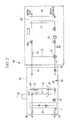
- a multi-type air conditioner 1 a plurality of indoor units 3A, 3B and a water temperature regulation apparatus 40 are connected in parallel with each other to one outdoor unit 2 between a gas-side pipe 4 and a liquid-side pipe 5 drawn from the outdoor unit 2.
- the outdoor unit 2 includes: an inverter-driven compressor 10 that compresses a refrigerant; an oil separator 11 that separates lubricant oil from a gas refrigerant; a four-way selector valve 12 that makes switching among circulation directions of the refrigerant; an outdoor heat exchanger 13 that performs heat exchange between the refrigerant and an outdoor heat source such as outdoor air; a supercooling coil 14 configured integrally with the outdoor heat exchanger 13; an outdoor expansion valve (EEVH) 15; a reservoir 16 that stores a liquid refrigerant therein; a supercooling heat exchanger 17 that supercools the liquid refrigerant; an expansion valve for supercooling (EEVSC) 18 that controls the amount of refrigerant whose flow is to be branched into the supercooling heat exchanger 17; an accumulator 19 that separates a liquid component from the gas refrigerant to be suctioned by the compressor 10 and enables the compressor 10 to suction only a gas component; a gas-side operation valve 20
- the above-mentioned elements of the outdoor unit 2 are connected by a refrigerant pipe 22 according to a known method, and form an outdoor refrigerant circuit 23.
- the outdoor unit 2 also includes an oil returning circuit 25 between the oil separator 11 and a suction pipe of the compressor 10, and the oil returning circuit 25 returns the lubricant oil that is separated from the discharged gas refrigerant by the oil separator 11, to the compressor 10 by a predetermined amount.
- the outdoor unit 2 further includes an outdoor controller 26, and the outdoor controller 26 controls the compressor 10, the four-way selector valve 12, the outdoor expansion valve (EEVH) 15, the expansion valve for supercooling (EEVSC) 18, and the like.
- the gas-side pipe 4 and the liquid-side pipe 5 are refrigerant pipes that are respectively connected to the gas-side operation valve 20 and the liquid-side operation valve 21 of the outdoor unit 2. With this configuration, a sealed one-system refrigerant circuit 7 is formed.
- the indoor units 3A, 3B each include: an indoor heat exchanger 30 that performs heat exchange between indoor air and the refrigerant, for indoor air conditioning; and an indoor expansion valve (EEVC) 31.
- the indoor units 3A, 3B are connected to the gas-side pipe 4 and the liquid-side pipe 5 through indoor branched gas-side pipes 4A, 4B and indoor branched liquid-side pipes 5A, 5B, respectively.
- the indoor units 3A, 3B also each include an indoor controller 33 that controls the indoor expansion valve (EEVC) 31 and the like. Note that the indoor controller 33 of each indoor unit 3A, 3B is connected to the outdoor controller 26.
- An air cooling operation of the multi-type air conditioner 1 described above is performed in the following manner.
- lubricant oil contained in the refrigerant is separated by the oil separator 11.
- the gas refrigerant is fed to the outdoor heat exchanger 13 by the four-way selector valve 12, and is subjected to heat exchange with the outdoor air by the outdoor heat exchanger 13, to be thereby condensed and liquefied.
- the speed of the compressor 10 is controlled by the outdoor controller 26 such that a low pressure of the refrigerant is the target value.
- the resultant liquid refrigerant is further cooled by the supercooling coil 14, then passes through the outdoor expansion valve 15, and is once stored in the reservoir 16.
- the liquid refrigerant whose amount of circulation has been adjusted by the reservoir 16 passes through the supercooling heat exchanger 17, and is circulated in the liquid refrigerant pipe. At this time, the liquid refrigerant is subjected to heat exchange with the refrigerant whose flow is branched from the liquid refrigerant pipe and which is adiabatically expanded by the expansion valve for supercooling (EEVSC) 18, so that a degree of supercooling is given to the liquid refrigerant.
- the liquid refrigerant passes through the liquid-side operation valve 21, and is guided out of the outdoor unit 2 into the liquid-side pipe 5. Moreover, the flow of the liquid refrigerant guided out into the liquid-side pipe 5 is branched into the respective branched liquid-side pipes 5A, 5B of the indoor units 3A, 3B.
- EEVC indoor expansion valve
- the indoor heat exchanger 30 heat exchange is performed between the indoor air and the refrigerant, and the indoor air is thus cooled to be used for indoor air cooling.
- the refrigerant is gasified, passes through each branched gas-side pipe 4A, 4B, and joins the gas refrigerants from the other indoor units, in the gas-side pipe 4.
- the degree of opening of the indoor expansion valve (EEVC) 31 is controlled by the indoor controller 33 such that the degree of refrigerant exit superheating of the indoor heat exchanger 30 that functions as an evaporator is the target value.
- the gas refrigerant joined together in the gas-side pipe 4 returns again to the outdoor unit 2, passes through the gas-side operation valve 20 and the four-way selector valve 12, joins the gas refrigerant from the supercooling heat exchanger 17, and is then introduced into the accumulator 19.
- the liquid component contained in the gas refrigerant is separated by the accumulator 19, and only the gas component is suctioned by the compressor 10.
- the suctioned refrigerant is compressed again by the compressor 10.
- the air cooling operation is performed through repetition of the above-mentioned cycle.
- the gas refrigerant is fed to the gas-side operation valve 20 by the four-way selector valve 12. Note that, at the time of the air heating operation, the speed of the compressor 10 is controlled by the outdoor controller 26 such that a high pressure of the refrigerant is the target value.
- the refrigerant fed to the gas-side operation valve 20 is guided out of the outdoor unit 2 through the gas-side pipe 4, and is introduced into the plurality of indoor units 3A, 3B through the indoor branched gas-side pipes 4A, 4B.
- the high-temperature high-pressure gas refrigerant introduced into the indoor unit 3A, 3B is subjected to heat exchange with the indoor air by the indoor heat exchanger 30, and the indoor air is thus heated to be used for indoor air heating.
- the liquid refrigerant condensed by the indoor heat exchanger 30 passes through the indoor expansion valve 31 and the branched liquid-side pipe 5A, 5B, joins the refrigerants from the other indoor units, and is then returned to the outdoor unit 2 through the liquid-side pipe 5.
- the degree of opening of the indoor expansion valve 31 is controlled by the indoor controller 33 such that the refrigerant exit temperature or the degree of refrigerant supercooling of the indoor heat exchanger 30 that functions as a condenser is the target value.
- the refrigerant returned to the outdoor unit 2 reaches the supercooling heat exchanger 17 through the liquid-side operation valve 21, and is supercooled similarly to the air cooling operation. After that, the refrigerant flows into the reservoir 16, and is once stored therein, whereby the amount of circulation thereof is adjusted.
- the resultant liquid refrigerant is supplied to the outdoor expansion valve (EEVH) 15 to be adiabatically expanded, and then flows into the outdoor heat exchanger 13 through the supercooling coil 14.
- Heat exchange is performed between the outdoor air and the refrigerant by the outdoor heat exchanger 13, and the refrigerant absorbs heat from the outdoor air to be evaporated and gasified.
- the resultant refrigerant passes through the four-way selector valve 12 from the outdoor heat exchanger 13, joins the gas refrigerant from the supercooling heat exchanger 17, and is then introduced into the accumulator 19.
- the liquid component contained in the gas refrigerant is separated by the accumulator 19, and only the gas component is suctioned by the compressor 10.
- the suctioned refrigerant is compressed again by the compressor 10.
- the air heating operation is performed through repetition of the above-mentioned cycle.
- the water temperature regulation apparatus 40 regulates the temperature of water used by water utilizing equipment, and includes a water temperature regulation unit 50, a water temperature regulation tank 60, and a water temperature regulation controller 45 that is connected to the outdoor controller 26 and controls the elements of the water temperature regulation apparatus 40.
- the water temperature regulation unit 50 and the water temperature regulation tank 60 are connected to each other by water pipes 61, 62, and a pump 63 provided to the water pipe 62 circulates water through the water pipes 61, 62 between the water temperature regulation unit 50 and the water temperature regulation tank 60. With this configuration, a sealed one-system water circuit 64 is formed.
- the water temperature regulation unit 50 includes: a water heat exchanger 51; an expansion valve (EEV) 52 provided to a branched liquid-side pipe 5C branched from the liquid-side pipe 5; and a bypass pipe 53 that connects a branched gas-side pipe 4C branched from the gas-side pipe 4 and the branched liquid-side pipe 5C branched from the liquid-side pipe 5, to thereby bypass the water heat exchanger 51.
- EEV expansion valve
- the water heat exchanger 51 is formed of, for example, a plate heat exchanger, and performs heat exchange between: a channel Ch1 that connects the branched gas-side pipe 4C and the branched liquid-side pipe 5C in the multi-type air conditioner 1 (refrigerant circuit 7); and a channel Ch2 that connects the water pipe 61 and the water pipe 62 in the water utilizing equipment (water circuit 64).
- the channel Ch2 of the water heat exchanger 51 is provided with a water temperature sensor 65 or a thermistor 66 that detects the entrance water temperature thereof and a water temperature sensor 67 or a thermistor 68 that detects the exit water temperature thereof.
- the water temperature regulation tank 60 includes a heat exchanger 71 inside of a tank 70.
- the heat exchanger 71 performs heat exchange between water in the tank 70 and water in the water circuit 64, to thereby heat or cool the water in the tank 70 and regulate the temperature thereof.
- the temperature-regulated water in the tank 70 is sent out to the water utilizing equipment to be used for intended purposes such as floor heating and air heating.
- a bypass 72 and a water control valve 73 are provided between the water pipes 61, 62.
- a connection portion between the bypass 72 and the water pipe 61 is provided with a sensor 74 that detects the exit water temperature thereof.
- the outdoor controller 26 and the water temperature regulation controller 45 work in cooperation with each other, whereby the operation is controlled according to a flow as shown in Fig. 3 .
- the outdoor controller 26 acquires information on operation states from the respective indoor controllers 33 of the other indoor units 3A, 3B and the water temperature regulation controller 45 of the water temperature regulation apparatus 40 (Step S101).
- the outdoor controller 26 acquires, from the water temperature regulation controller 45, information on a target exit water temperature (set temperature) T1 that is set to the water temperature regulation controller 45 by a user.
- the outdoor controller 26 also acquires, from the water temperature regulation controller 45, information on an exit water temperature To of the water heat exchanger 51 detected by the thermistor 68.
- a target pressure P1 in the refrigerant circuit 7 of the outdoor unit 2 is set (corrected) such that the exit water temperature To approaches the target exit water temperature T1.
- the target pressure P1 is set to a high pressure side of the refrigerant circuit 7.
- the target pressure P1 is set to a low pressure side of the refrigerant circuit 7.
- the target pressure P1 in the refrigerant circuit 7 is increased.
- the target pressure P1 in the refrigerant circuit 7 is increased.
- Such sampling of the target exit water temperature T1 and the exit water temperature To as described above is repeated at regular time intervals, and the target pressure P1 is adjusted until a difference between the target exit water temperature T1 and the exit water temperature To becomes a prescribed value (for example, 0 degrees) set in advance.
- the target exit water temperature T1 is regulated by the following start-stop operation. That is, when the target pressure is adjusted, in the case where the exit water temperature To becomes lower (at the time of the air cooling operation) and higher (at the time of the air heating operation) by the prescribed value or more than the target exit water temperature T1 continuously for a prescribed length of time or more, the operation of the water temperature regulation apparatus 40 is stopped. If the temperature difference becomes smaller, the operation thereof is restarted.
- the target pressure P1 of the refrigerant in the refrigerant circuit 7 of the outdoor unit 2 can be lower (at the time of the air heating operation) and higher (at the time of the air cooling operation), compared with the case where the indoor units 3A, 3B perform the air cooling operation or the air heating operation. Accordingly, the outdoor unit 2 can perform an energy-saving operation.
- the water temperature regulation unit 50 can achieve the adjustment of the degree of superheating (at the time of the air cooling operation) and the degree of supercooling (at the time of the air heating operation) by adjusting the degree of opening of the expansion valve 52, so as to make the maximum use of the capability of the water heat exchanger 51. Accordingly, the water temperature regulation unit 50 can perform an efficient operation.
- Step S104 if at least one of the other indoor units 3A, 3B performs the air cooling operation or the air heating operation, the transition is made to a mixed operation mode (Step S104).
- the outdoor controller 26 acquires, from each of the indoor controller 33 and the water temperature regulation controller 45 of the water temperature regulation apparatus 40, information on the operation state thereof. Then, similarly to a normal multi-type air conditioner not including the water temperature regulation apparatus 40, the target pressure P1 in the refrigerant circuit 7 of the outdoor unit 2 is set as appropriate in accordance with the set temperature in each indoor unit 3A, 3B.
- the outdoor controller 26 sends a signal indicating that a mixed operation is currently performed, to the water temperature regulation controller 45.
- the water temperature regulation controller 45 Upon the reception of this signal, the water temperature regulation controller 45 checks which of an "air conditioning priority mode (second-1 mode)" by each indoor unit 3A, 3B and a “water temperature regulation priority mode (second-2 mode)" by the water temperature regulation controller 45 is set in the entire system of the multi-type air conditioner 1 (Steps S105 and S106).
- the target pressure P1 in the refrigerant circuit 7 of the outdoor unit 2 is set in accordance with the set temperature of each indoor unit 3A, 3B, and hence the refrigerant pressure is more than necessary in the water heat exchanger 51 of the water temperature regulation unit 50. Accordingly, the water temperature regulation controller 45 makes the transition to a capability 100% maintaining operation, in which the capability of the water heat exchanger 51 does not become equal to or more than 100% and is maintained around 100% (Step S107).
- the degree of opening of the expansion valve 52 is controlled, and the degree of superheating (at the time of the air cooling operation) or the degree of supercooling (at the time of the air heating operation) is adjusted, whereby the capability of the water heat exchanger 51 does not become equal to or more than 100% and is maintained around 100%.
- the water temperature regulation controller 45 acquires information on an entrance water temperature Ti and the exit water temperature To of the water heat exchanger 51 detected by the thermistor 66, 68. Then, the absolute value of a temperature difference ⁇ T between the entrance water temperature Ti and the exit water temperature To is controlled so as not to become equal to or more than a prescribed value set in advance at which the capability of the water heat exchanger 51 becomes 100%. For example, in the case of the water heat exchanger 51 in which the temperature difference between the entrance side and the exit side is X degrees in its capability 100% state, the degree of opening of the expansion valve 52 is controlled such that the absolute value of the temperature difference ⁇ T between the detected entrance water temperature Ti and the detected exit water temperature To falls within X degrees.
- the degree of opening of the expansion valve 52 is reduced, and the target degree of superheating of the refrigerant in the channel Ch1 is increased by a predetermined value (for example, 1 degree), and
- the degree of opening of the expansion valve 52 is increased, and the target degree of superheating of the refrigerant in the channel Ch1 is reduced by a predetermined value (for example, 1 degree).
- the degree of opening of the expansion valve 52 is reduced, and the target degree of supercooling of the refrigerant in the channel Ch1 is increased by a predetermined value (for example, 1 degree), and
- the degree of opening of the expansion valve 52 is increased, and the target degree of supercooling of the refrigerant in the channel Ch1 is reduced by a predetermined value (for example, 1 degree).
- the target pressure P1 in the refrigerant circuit 7 of the outdoor unit 2 is set in accordance with the set temperature of each indoor unit 3A, 3B, and hence the refrigerant pressure is more than necessary in the water heat exchanger 51 of the water temperature regulation unit 50.
- the capability of the water heat exchanger 51 is controlled so as not to become equal to or more than 100%, such an operation that prioritizes indoor air conditioning by the indoor unit 3A, 3B can be performed, while an excessive capability of the water temperature regulation apparatus 40 and an insufficient capability of the indoor unit 3A, 3B are avoided.
- the water temperature regulation controller 45 can make the transition to a capability suppressing operation, in the case where the difference between the target exit water temperature T1 set by the user and the entrance water temperature Ti is equal to or less than X degrees that is the difference between the entrance side and the exit side in the capability 100% state of the water heat exchanger 51.
- the capability suppressing operation the degree of opening of the expansion valve 52 is further adjusted, and the operation is controlled in the state where the capability of the water heat exchanger 51 is suppressed to be less than 100% (Steps S108 and S109).
- the degree of opening of the expansion valve 52 is reduced, and the target degree of superheating of the refrigerant in the channel Ch1 is increased by a predetermined value (for example, 1 degree), and
- the degree of opening of the expansion valve 52 is increased, and the target degree of superheating of the refrigerant in the channel Ch1 is reduced by a predetermined value (for example, 1 degree).
- the degree of opening of the expansion valve 52 is reduced, and the target degree of supercooling of the refrigerant in the channel Ch1 is increased by a predetermined value (for example, 1 degree), and if the exit water temperature To - the target exit water temperature T1 ⁇ -0.5 degrees, the degree of opening of the expansion valve 52 is increased, and the target degree of supercooling of the refrigerant in the channel Ch1 is reduced by a predetermined value (for example, 1 degree).
- the capability of the water heat exchanger 51 of the water temperature regulation unit 50 is controlled by the expansion valve 52 so as to be suppressed to be less than 100%, whereby the lower limit of the capability that can be adjusted for the water temperature regulation apparatus 40 can be expanded even without the water control valve 73 to be described later.
- the degree of opening of the water control valve 73 is adjusted, whereby the operation can also be controlled in the state where the capability of the water heat exchanger 51 is suppressed to be less than 100% (Steps S110 and S111).
- the degree of opening of the water control valve 73 is changed, the amount of water that bypasses the water heat exchanger 51 through the bypass 72 can be adjusted, and the temperature of water supplied to the heat exchanger 71 of the water temperature regulation tank 60 can be adjusted, after a connection portion between the bypass 72 and the water pipe 62
- the change amount in degree of opening ⁇ P of the water control valve 73 may be determined on the basis of this map, and the adjustment of the degree of opening of the water control valve 73 may be controlled.
- Step S106 if the "water temperature regulation priority mode" by the water temperature regulation controller 45 is set in the entire system of the multi-type air conditioner 1, the water temperature regulation controller 45 acquires information on the entrance water temperature Ti and the exit water temperature To of the water heat exchanger 51. Then, a water temperature regulation priority operation can be performed such that the absolute value of the temperature difference ⁇ T between the entrance water temperature Ti and the exit water temperature To approaches the target exit water temperature T1 even if the capability of the water heat exchanger 51 becomes equal to or more than 100% (Step S112).
- the water temperature regulation controller 45 acquires information on the entrance water temperature Ti and the exit water temperature To of the water heat exchanger 51 detected by the thermistor 66, 68. Then, in the water heat exchanger 51 in which the temperature difference between the entrance side and the exit side is X degrees in its capability 100% state, even if the absolute value of the temperature difference ⁇ T between the entrance water temperature Ti and the exit water temperature To becomes equal to or more than X degrees, the degrees of opening of the expansion valve 52 and the water control valve 73 are not adjusted, and the operation is continued such that the exit water temperature To approaches the target exit water temperature T1.
- the water temperature regulation apparatus 40 can be prioritized, and the usage range can be expanded by an appropriate selection depending on an intended purpose and the like of the user.
- the operation can be performed in the state where the target pressure of the refrigerant is set to a level matched with the indoor units 3A, 3B.
- the water temperature regulation apparatus 40 can be easily provided thereto without the need to change basic control in the indoor units 3A, 3B.
- the number of the provided water temperature regulation apparatuses 40 is only one, but may be more than one.
- control similar to that in the above-mentioned single operation mode of the water temperature regulation apparatus 40 is carried out so as to follow the highest-load water temperature regulation apparatus 40 in which the absolute value of the difference between the target exit water temperature T1 and the actual exit water temperature To is largest.
- the water temperature regulation controller 45 of each of the plurality of water temperature regulation apparatuses 40 carries out control similar to that in the above-mentioned mixed operation mode.
- the configuration of the multi-type air conditioner 1 is not limited to the configuration exemplified above, and may be other configurations.
- the present invention can be similarly applied to such a multi-type air conditioner 1' as illustrated in Fig. 5 .
- the outdoor unit 2 a plurality of indoor units 3A, 3B, 3C, and the water temperature regulation apparatus 40 are connected to each other by a high-pressure gas pipe 57, a low-pressure gas pipe 59, and the liquid-side pipe 5, and the plurality of indoor units 3A, 3B, 3C and the water temperature regulation apparatus 40 can mixedly perform the air cooling operation and the air heating operation.
- the outdoor unit 2 includes a plurality of, for example, two four-way selector valves 12.
- Each four-way selector valve 12 has: one port connected to the high-pressure gas pipe 57 located in the outdoor unit 2; another port connected to the outdoor heat exchanger 13; still another port that is connected to the low-pressure gas pipe 59 by a branched low-pressure gas pipe 87; and the other port that is connected to the branched low-pressure gas pipe 87 through a strainer and a capillary tube.
- the indoor units 3A, 3B, 3C and the water temperature regulation apparatus 40 each include a branched-flow controller 95 that makes switching between the high-pressure gas pipe 57 and the low-pressure gas pipe 59.
- the branched-flow controller 95 includes: an indoor four-way valve 97 that makes switching between connection of the high-pressure gas pipe 57 and the indoor heat exchanger 30 and connection of the low-pressure gas pipe 59 and the indoor heat exchanger 30; and a high-pressure low-pressure bypass pipe 99 that connects the high-pressure gas pipe 57 and the low-pressure gas pipe 59.
- An air cooling/heating operation of the multi-type air conditioner 1' described above is performed in the following manner.
- the high-temperature high-pressure gas refrigerant compressed by the compressor 10 is discharged into the high-pressure gas pipe 57, and is sent to the indoor units 3A, 3B, 3C and the water temperature regulation apparatus 40.
- part of the high-temperature high-pressure gas refrigerant discharged into the high-pressure gas pipe 57 is branched to be sent to the outdoor heat exchanger 13 through the four-way selector valve 12, and is subjected to heat exchange with the outdoor air by the outdoor heat exchanger 13, to be thereby condensed and liquefied into a liquid refrigerant.
- This liquid refrigerant passes through the outdoor expansion valve 15, and is once stored in the reservoir 16, where the amount of circulation thereof is adjusted.
- the liquid refrigerant from the reservoir 16 is subjected to heat exchange with the refrigerant adiabatically expanded by the electronic expansion valve for supercooling (EEVSC) 18, while passing through the supercooling heat exchanger 17, so that the liquid refrigerant is cooled to a predetermined degree of supercooling.
- EVSC electronic expansion valve for supercooling
- the liquid refrigerant to which the predetermined degree of supercooling is given is guided out of the outdoor unit 2 into the liquid-side pipe 5.
- the high-pressure gas pipe 57 and the indoor heat exchanger 30 are connected to each other by operating the indoor four-way valve 97, and the high-temperature high-pressure gas refrigerant is introduced from the high-pressure gas pipe 57 into the indoor heat exchanger 30.
- the introduced high-temperature high-pressure gas refrigerant is subjected to heat exchange with the indoor air by the indoor heat exchanger 30, and the indoor air is thus heated to be used for indoor air heating.
- the gas refrigerant is cooled by the indoor air to be condensed and liquefied into a liquid refrigerant, and the liquid refrigerant flows into the liquid-side pipe 5 through the indoor electronic expansion valve (EEVC) 31.
- EEVC indoor electronic expansion valve
- the low-pressure gas pipe 59 and the indoor heat exchanger 30 are connected to each other by operating the indoor four-way valve 97.
- the liquid refrigerant that flows in from the liquid-side pipe 5 is adiabatically expanded by the indoor electronic expansion valve (EEVC) 31, and flows as a gas-liquid two-phase flow into the indoor heat exchanger 30.
- EEVC indoor electronic expansion valve
- Heat exchange is performed between the indoor air and the refrigerant by the indoor heat exchanger 30, and the indoor air is thus cooled to be used for indoor air cooling.
- the refrigerant is gasified, and is guided out into the low-pressure gas pipe 59 to be returned to the outdoor unit 2.
- some of the plurality of indoor units 3A, 3B, 3C may perform the air cooling operation, and, at the same time, some of the plurality of indoor units 3A, 3B, 3C may perform the air heating operation.
- the water temperature regulation apparatus 40 regulates the water temperature, such mixed operations of the indoor units 3A, 3B, 3C are determined for each of the air cooling operation and the air heating operation.
- the target exit water temperature T1 the entrance water temperature Ti, and the exit water temperature To are used as parameters detected for the adjustment of the degrees of opening of the expansion valve 52 and the water control valve 73, but other parameters may be adopted as appropriate as long as similar control can be performed.
- the plurality of modes for water temperature regulation are described, but all of the modes do not necessarily need to be provided, and part thereof may be omitted. Further, if the operation in the plurality of modes can be performed similarly to the above as a whole, the order of control and the like may be changed as appropriate.
Landscapes
- Engineering & Computer Science (AREA)
- Physics & Mathematics (AREA)
- Mechanical Engineering (AREA)
- Thermal Sciences (AREA)
- General Engineering & Computer Science (AREA)
- Chemical & Material Sciences (AREA)
- Combustion & Propulsion (AREA)
- Air Conditioning Control Device (AREA)
- Compression-Type Refrigeration Machines With Reversible Cycles (AREA)
Applications Claiming Priority (1)
| Application Number | Priority Date | Filing Date | Title |
|---|---|---|---|
| JP2012252547A JP6129520B2 (ja) | 2012-11-16 | 2012-11-16 | マルチ型空気調和機及びマルチ型空気調和機の制御方法 |
Publications (2)
| Publication Number | Publication Date |
|---|---|
| EP2733441A2 true EP2733441A2 (de) | 2014-05-21 |
| EP2733441A3 EP2733441A3 (de) | 2018-04-04 |
Family
ID=49578196
Family Applications (1)
| Application Number | Title | Priority Date | Filing Date |
|---|---|---|---|
| EP13192866.5A Withdrawn EP2733441A3 (de) | 2012-11-16 | 2013-11-14 | Multityp-Klimaanlage |
Country Status (2)
| Country | Link |
|---|---|
| EP (1) | EP2733441A3 (de) |
| JP (1) | JP6129520B2 (de) |
Cited By (5)
| Publication number | Priority date | Publication date | Assignee | Title |
|---|---|---|---|---|
| EP3205955A1 (de) * | 2016-02-12 | 2017-08-16 | Mitsubishi Heavy Industries Thermal Systems, Ltd. | Klimaanlage |
| EP3205954A1 (de) * | 2016-02-12 | 2017-08-16 | Mitsubishi Heavy Industries Thermal Systems, Ltd. | Kältekreislaufvorrichtung |
| CN109373543A (zh) * | 2018-10-15 | 2019-02-22 | 广东美的制冷设备有限公司 | 一拖多空调器及其控制方法、装置和计算机可读存储介质 |
| EP3722689A1 (de) * | 2019-04-09 | 2020-10-14 | Sustainable Energy Limited | Steuerungssystem zur anpassung der lufttemperatur, feuchtigkeit und wassertemperatur durch einen aussenluftwärmetauscher |
| CN114322205A (zh) * | 2020-09-30 | 2022-04-12 | 广东美的精密模具科技有限公司 | 空调器及其化霜方法、控制装置和可读存储介质 |
Families Citing this family (4)
| Publication number | Priority date | Publication date | Assignee | Title |
|---|---|---|---|---|
| JP6522162B2 (ja) * | 2016-01-08 | 2019-05-29 | 三菱電機株式会社 | 空気調和装置 |
| CN109373542A (zh) * | 2018-10-09 | 2019-02-22 | 广东美的制冷设备有限公司 | 一拖多空调器及其控制方法、装置和计算机可读存储介质 |
| CN109780677A (zh) * | 2018-12-20 | 2019-05-21 | 中冶置业集团有限公司 | 一种多模式空调 |
| JP2020201019A (ja) * | 2019-06-13 | 2020-12-17 | 三菱重工エンジン&ターボチャージャ株式会社 | コジェネレーションシステム、制御方法及びプログラム |
Citations (2)
| Publication number | Priority date | Publication date | Assignee | Title |
|---|---|---|---|---|
| JPH08261599A (ja) | 1995-03-24 | 1996-10-11 | Kyushu Electric Power Co Inc | 空気調和装置 |
| JP2008281319A (ja) | 2007-05-09 | 2008-11-20 | Inter Central:Kk | 空調室外機接続型冷温水式床冷暖房ユニット |
Family Cites Families (7)
| Publication number | Priority date | Publication date | Assignee | Title |
|---|---|---|---|---|
| JPH0618123A (ja) * | 1992-07-06 | 1994-01-25 | Matsushita Electric Ind Co Ltd | 空調給湯装置 |
| JP2003322388A (ja) * | 2002-05-02 | 2003-11-14 | Toshiba Kyaria Kk | 空気調和機 |
| JP5428381B2 (ja) * | 2009-02-24 | 2014-02-26 | ダイキン工業株式会社 | ヒートポンプシステム |
| KR101045435B1 (ko) * | 2009-02-26 | 2011-06-30 | 엘지전자 주식회사 | 냉매사이클 연동 물 순환 시스템 |
| JP5228023B2 (ja) * | 2010-10-29 | 2013-07-03 | 三菱電機株式会社 | 冷凍サイクル装置 |
| WO2012081052A1 (ja) * | 2010-12-15 | 2012-06-21 | 三菱電機株式会社 | 空調給湯複合システム |
| JP2012141113A (ja) * | 2011-01-06 | 2012-07-26 | Daikin Industries Ltd | 空気調和温水機器システム |
-
2012
- 2012-11-16 JP JP2012252547A patent/JP6129520B2/ja active Active
-
2013
- 2013-11-14 EP EP13192866.5A patent/EP2733441A3/de not_active Withdrawn
Patent Citations (2)
| Publication number | Priority date | Publication date | Assignee | Title |
|---|---|---|---|---|
| JPH08261599A (ja) | 1995-03-24 | 1996-10-11 | Kyushu Electric Power Co Inc | 空気調和装置 |
| JP2008281319A (ja) | 2007-05-09 | 2008-11-20 | Inter Central:Kk | 空調室外機接続型冷温水式床冷暖房ユニット |
Cited By (7)
| Publication number | Priority date | Publication date | Assignee | Title |
|---|---|---|---|---|
| EP3205955A1 (de) * | 2016-02-12 | 2017-08-16 | Mitsubishi Heavy Industries Thermal Systems, Ltd. | Klimaanlage |
| EP3205954A1 (de) * | 2016-02-12 | 2017-08-16 | Mitsubishi Heavy Industries Thermal Systems, Ltd. | Kältekreislaufvorrichtung |
| CN109373543A (zh) * | 2018-10-15 | 2019-02-22 | 广东美的制冷设备有限公司 | 一拖多空调器及其控制方法、装置和计算机可读存储介质 |
| US11680725B2 (en) | 2018-10-15 | 2023-06-20 | Gd Midea Air-Conditioning Equipment Co., Ltd. | Multi-split air conditioner, control method and device thereof, and computer readable storage medium |
| EP3722689A1 (de) * | 2019-04-09 | 2020-10-14 | Sustainable Energy Limited | Steuerungssystem zur anpassung der lufttemperatur, feuchtigkeit und wassertemperatur durch einen aussenluftwärmetauscher |
| CN114322205A (zh) * | 2020-09-30 | 2022-04-12 | 广东美的精密模具科技有限公司 | 空调器及其化霜方法、控制装置和可读存储介质 |
| CN114322205B (zh) * | 2020-09-30 | 2023-03-07 | 广东美的精密模具科技有限公司 | 空调器及其化霜方法、控制装置和可读存储介质 |
Also Published As
| Publication number | Publication date |
|---|---|
| JP2014102011A (ja) | 2014-06-05 |
| EP2733441A3 (de) | 2018-04-04 |
| JP6129520B2 (ja) | 2017-05-17 |
Similar Documents
| Publication | Publication Date | Title |
|---|---|---|
| EP2733441A2 (de) | Multityp-Klimaanlage | |
| US9791194B2 (en) | Air-conditioning apparatus | |
| EP2889554B1 (de) | Klimaanlagensystem | |
| US7155928B2 (en) | Refrigerating apparatus | |
| EP2416081A1 (de) | Luftklimatisierungsvorrichtung | |
| JP5182358B2 (ja) | 冷凍装置 | |
| EP3587948B1 (de) | Klimaanlage | |
| AU2016346536B2 (en) | Air conditioning apparatus | |
| KR102558826B1 (ko) | 공기 조화 시스템 및 제어 방법 | |
| EP1431677B1 (de) | Klimaanlage | |
| CN114110739B (zh) | 一拖多制冷制热空调机 | |
| JP2014181869A (ja) | 空気調和機 | |
| EP1881277A1 (de) | Klimaanlage | |
| JP2008039234A (ja) | 空気調和装置 | |
| EP3109566A1 (de) | Klimaanlagenvorrichtung | |
| US11112151B2 (en) | Heat source unit for refrigeration apparatus including a heat-source-side heat exchanger having a heat exchange region of variable size | |
| JP2009144939A (ja) | マルチ空気調和システム | |
| EP3104102B1 (de) | Klimaanlage und betriebsverfahren dafür | |
| EP3165844B1 (de) | Klimatisierungsvorrichtung | |
| KR101995583B1 (ko) | 공기조화기 및 그 제어방법 | |
| JP5517891B2 (ja) | 空気調和装置 | |
| JP6407410B2 (ja) | 冷凍空調装置 | |
| JP2003106615A (ja) | 空気調和装置 | |
| KR102390900B1 (ko) | 멀티형 공기조화기 및 그의 제어방법 | |
| JP5537906B2 (ja) | 空気調和装置 |
Legal Events
| Date | Code | Title | Description |
|---|---|---|---|
| PUAI | Public reference made under article 153(3) epc to a published international application that has entered the european phase |
Free format text: ORIGINAL CODE: 0009012 |
|
| 17P | Request for examination filed |
Effective date: 20131114 |
|
| AK | Designated contracting states |
Kind code of ref document: A2 Designated state(s): AL AT BE BG CH CY CZ DE DK EE ES FI FR GB GR HR HU IE IS IT LI LT LU LV MC MK MT NL NO PL PT RO RS SE SI SK SM TR |
|
| AX | Request for extension of the european patent |
Extension state: BA ME |
|
| RAP1 | Party data changed (applicant data changed or rights of an application transferred) |
Owner name: MITSUBISHI HEAVY INDUSTRIES THERMAL SYSTEMS, LTD. |
|
| PUAL | Search report despatched |
Free format text: ORIGINAL CODE: 0009013 |
|
| AK | Designated contracting states |
Kind code of ref document: A3 Designated state(s): AL AT BE BG CH CY CZ DE DK EE ES FI FR GB GR HR HU IE IS IT LI LT LU LV MC MK MT NL NO PL PT RO RS SE SI SK SM TR |
|
| AX | Request for extension of the european patent |
Extension state: BA ME |
|
| RIC1 | Information provided on ipc code assigned before grant |
Ipc: F25B 49/02 20060101ALI20180301BHEP Ipc: F25B 13/00 20060101AFI20180301BHEP |
|
| R17P | Request for examination filed (corrected) |
Effective date: 20181004 |
|
| RBV | Designated contracting states (corrected) |
Designated state(s): AL AT BE BG CH CY CZ DE DK EE ES FI FR GB GR HR HU IE IS IT LI LT LU LV MC MK MT NL NO PL PT RO RS SE SI SK SM TR |
|
| STAA | Information on the status of an ep patent application or granted ep patent |
Free format text: STATUS: THE APPLICATION HAS BEEN WITHDRAWN |
|
| 18W | Application withdrawn |
Effective date: 20191120 |