EP2734012A1 - Lampe à LED avec pilote intégré - Google Patents
Lampe à LED avec pilote intégré Download PDFInfo
- Publication number
- EP2734012A1 EP2734012A1 EP13195218.6A EP13195218A EP2734012A1 EP 2734012 A1 EP2734012 A1 EP 2734012A1 EP 13195218 A EP13195218 A EP 13195218A EP 2734012 A1 EP2734012 A1 EP 2734012A1
- Authority
- EP
- European Patent Office
- Prior art keywords
- led
- driver
- printed circuit
- circuit board
- temperature
- Prior art date
- Legal status (The legal status is an assumption and is not a legal conclusion. Google has not performed a legal analysis and makes no representation as to the accuracy of the status listed.)
- Withdrawn
Links
- 239000000919 ceramic Substances 0.000 claims abstract description 33
- 239000003990 capacitor Substances 0.000 claims abstract description 11
- 238000009499 grossing Methods 0.000 claims abstract description 5
- 229910052782 aluminium Inorganic materials 0.000 claims abstract description 3
- XAGFODPZIPBFFR-UHFFFAOYSA-N aluminium Chemical compound [Al] XAGFODPZIPBFFR-UHFFFAOYSA-N 0.000 claims abstract description 3
- 238000001465 metallisation Methods 0.000 claims description 22
- 230000001419 dependent effect Effects 0.000 claims description 7
- 150000001875 compounds Chemical class 0.000 claims description 3
- 230000001276 controlling effect Effects 0.000 claims description 3
- 230000005669 field effect Effects 0.000 claims description 3
- 238000004382 potting Methods 0.000 claims description 3
- 230000001105 regulatory effect Effects 0.000 claims description 2
- 239000002243 precursor Substances 0.000 claims 2
- 238000001914 filtration Methods 0.000 abstract description 2
- 239000000758 substrate Substances 0.000 description 36
- 238000001816 cooling Methods 0.000 description 14
- 239000004020 conductor Substances 0.000 description 9
- 239000000969 carrier Substances 0.000 description 7
- 239000011521 glass Substances 0.000 description 4
- 230000017525 heat dissipation Effects 0.000 description 4
- 229910010293 ceramic material Inorganic materials 0.000 description 3
- 238000007373 indentation Methods 0.000 description 3
- 229910052751 metal Inorganic materials 0.000 description 3
- 239000002184 metal Substances 0.000 description 3
- 239000012080 ambient air Substances 0.000 description 2
- 230000007423 decrease Effects 0.000 description 2
- 230000000694 effects Effects 0.000 description 2
- 238000005286 illumination Methods 0.000 description 2
- 238000004519 manufacturing process Methods 0.000 description 2
- 239000000463 material Substances 0.000 description 2
- 238000013021 overheating Methods 0.000 description 2
- 230000005855 radiation Effects 0.000 description 2
- 239000004065 semiconductor Substances 0.000 description 2
- 238000005476 soldering Methods 0.000 description 2
- 101100390736 Danio rerio fign gene Proteins 0.000 description 1
- 101100390738 Mus musculus Fign gene Proteins 0.000 description 1
- 230000004913 activation Effects 0.000 description 1
- 239000000853 adhesive Substances 0.000 description 1
- 230000001070 adhesive effect Effects 0.000 description 1
- PNEYBMLMFCGWSK-UHFFFAOYSA-N aluminium oxide Inorganic materials [O-2].[O-2].[O-2].[Al+3].[Al+3] PNEYBMLMFCGWSK-UHFFFAOYSA-N 0.000 description 1
- 230000000712 assembly Effects 0.000 description 1
- 238000000429 assembly Methods 0.000 description 1
- 238000005266 casting Methods 0.000 description 1
- 239000003985 ceramic capacitor Substances 0.000 description 1
- 238000010276 construction Methods 0.000 description 1
- 238000010292 electrical insulation Methods 0.000 description 1
- 238000009413 insulation Methods 0.000 description 1
- 238000002955 isolation Methods 0.000 description 1
- TWNQGVIAIRXVLR-UHFFFAOYSA-N oxo(oxoalumanyloxy)alumane Chemical compound O=[Al]O[Al]=O TWNQGVIAIRXVLR-UHFFFAOYSA-N 0.000 description 1
- 230000001681 protective effect Effects 0.000 description 1
Images




Classifications
-
- F—MECHANICAL ENGINEERING; LIGHTING; HEATING; WEAPONS; BLASTING
- F21—LIGHTING
- F21K—NON-ELECTRIC LIGHT SOURCES USING LUMINESCENCE; LIGHT SOURCES USING ELECTROCHEMILUMINESCENCE; LIGHT SOURCES USING CHARGES OF COMBUSTIBLE MATERIAL; LIGHT SOURCES USING SEMICONDUCTOR DEVICES AS LIGHT-GENERATING ELEMENTS; LIGHT SOURCES NOT OTHERWISE PROVIDED FOR
- F21K9/00—Light sources using semiconductor devices as light-generating elements, e.g. using light-emitting diodes [LED] or lasers
- F21K9/20—Light sources comprising attachment means
- F21K9/23—Retrofit light sources for lighting devices with a single fitting for each light source, e.g. for substitution of incandescent lamps with bayonet or threaded fittings
-
- F—MECHANICAL ENGINEERING; LIGHTING; HEATING; WEAPONS; BLASTING
- F21—LIGHTING
- F21K—NON-ELECTRIC LIGHT SOURCES USING LUMINESCENCE; LIGHT SOURCES USING ELECTROCHEMILUMINESCENCE; LIGHT SOURCES USING CHARGES OF COMBUSTIBLE MATERIAL; LIGHT SOURCES USING SEMICONDUCTOR DEVICES AS LIGHT-GENERATING ELEMENTS; LIGHT SOURCES NOT OTHERWISE PROVIDED FOR
- F21K9/00—Light sources using semiconductor devices as light-generating elements, e.g. using light-emitting diodes [LED] or lasers
- F21K9/20—Light sources comprising attachment means
- F21K9/23—Retrofit light sources for lighting devices with a single fitting for each light source, e.g. for substitution of incandescent lamps with bayonet or threaded fittings
- F21K9/238—Arrangement or mounting of circuit elements integrated in the light source
-
- F—MECHANICAL ENGINEERING; LIGHTING; HEATING; WEAPONS; BLASTING
- F21—LIGHTING
- F21V—FUNCTIONAL FEATURES OR DETAILS OF LIGHTING DEVICES OR SYSTEMS THEREOF; STRUCTURAL COMBINATIONS OF LIGHTING DEVICES WITH OTHER ARTICLES, NOT OTHERWISE PROVIDED FOR
- F21V23/00—Arrangement of electric circuit elements in or on lighting devices
- F21V23/003—Arrangement of electric circuit elements in or on lighting devices the elements being electronics drivers or controllers for operating the light source, e.g. for a LED array
- F21V23/004—Arrangement of electric circuit elements in or on lighting devices the elements being electronics drivers or controllers for operating the light source, e.g. for a LED array arranged on a substrate, e.g. a printed circuit board
-
- F—MECHANICAL ENGINEERING; LIGHTING; HEATING; WEAPONS; BLASTING
- F21—LIGHTING
- F21V—FUNCTIONAL FEATURES OR DETAILS OF LIGHTING DEVICES OR SYSTEMS THEREOF; STRUCTURAL COMBINATIONS OF LIGHTING DEVICES WITH OTHER ARTICLES, NOT OTHERWISE PROVIDED FOR
- F21V23/00—Arrangement of electric circuit elements in or on lighting devices
- F21V23/003—Arrangement of electric circuit elements in or on lighting devices the elements being electronics drivers or controllers for operating the light source, e.g. for a LED array
- F21V23/004—Arrangement of electric circuit elements in or on lighting devices the elements being electronics drivers or controllers for operating the light source, e.g. for a LED array arranged on a substrate, e.g. a printed circuit board
- F21V23/006—Arrangement of electric circuit elements in or on lighting devices the elements being electronics drivers or controllers for operating the light source, e.g. for a LED array arranged on a substrate, e.g. a printed circuit board the substrate being distinct from the light source holder
-
- F—MECHANICAL ENGINEERING; LIGHTING; HEATING; WEAPONS; BLASTING
- F21—LIGHTING
- F21V—FUNCTIONAL FEATURES OR DETAILS OF LIGHTING DEVICES OR SYSTEMS THEREOF; STRUCTURAL COMBINATIONS OF LIGHTING DEVICES WITH OTHER ARTICLES, NOT OTHERWISE PROVIDED FOR
- F21V29/00—Protecting lighting devices from thermal damage; Cooling or heating arrangements specially adapted for lighting devices or systems
- F21V29/50—Cooling arrangements
- F21V29/70—Cooling arrangements characterised by passive heat-dissipating elements, e.g. heat-sinks
- F21V29/74—Cooling arrangements characterised by passive heat-dissipating elements, e.g. heat-sinks with fins or blades
- F21V29/77—Cooling arrangements characterised by passive heat-dissipating elements, e.g. heat-sinks with fins or blades with essentially identical diverging planar fins or blades, e.g. with fan-like or star-like cross-section
- F21V29/773—Cooling arrangements characterised by passive heat-dissipating elements, e.g. heat-sinks with fins or blades with essentially identical diverging planar fins or blades, e.g. with fan-like or star-like cross-section the planes containing the fins or blades having the direction of the light emitting axis
-
- F—MECHANICAL ENGINEERING; LIGHTING; HEATING; WEAPONS; BLASTING
- F21—LIGHTING
- F21V—FUNCTIONAL FEATURES OR DETAILS OF LIGHTING DEVICES OR SYSTEMS THEREOF; STRUCTURAL COMBINATIONS OF LIGHTING DEVICES WITH OTHER ARTICLES, NOT OTHERWISE PROVIDED FOR
- F21V31/00—Gas-tight or water-tight arrangements
- F21V31/04—Provision of filling media
-
- H—ELECTRICITY
- H05—ELECTRIC TECHNIQUES NOT OTHERWISE PROVIDED FOR
- H05B—ELECTRIC HEATING; ELECTRIC LIGHT SOURCES NOT OTHERWISE PROVIDED FOR; CIRCUIT ARRANGEMENTS FOR ELECTRIC LIGHT SOURCES, IN GENERAL
- H05B45/00—Circuit arrangements for operating light-emitting diodes [LED]
- H05B45/10—Controlling the intensity of the light
- H05B45/18—Controlling the intensity of the light using temperature feedback
-
- H—ELECTRICITY
- H05—ELECTRIC TECHNIQUES NOT OTHERWISE PROVIDED FOR
- H05B—ELECTRIC HEATING; ELECTRIC LIGHT SOURCES NOT OTHERWISE PROVIDED FOR; CIRCUIT ARRANGEMENTS FOR ELECTRIC LIGHT SOURCES, IN GENERAL
- H05B45/00—Circuit arrangements for operating light-emitting diodes [LED]
- H05B45/30—Driver circuits
-
- F—MECHANICAL ENGINEERING; LIGHTING; HEATING; WEAPONS; BLASTING
- F21—LIGHTING
- F21Y—INDEXING SCHEME ASSOCIATED WITH SUBCLASSES F21K, F21L, F21S and F21V, RELATING TO THE FORM OR THE KIND OF THE LIGHT SOURCES OR OF THE COLOUR OF THE LIGHT EMITTED
- F21Y2115/00—Light-generating elements of semiconductor light sources
- F21Y2115/10—Light-emitting diodes [LED]
-
- H—ELECTRICITY
- H05—ELECTRIC TECHNIQUES NOT OTHERWISE PROVIDED FOR
- H05B—ELECTRIC HEATING; ELECTRIC LIGHT SOURCES NOT OTHERWISE PROVIDED FOR; CIRCUIT ARRANGEMENTS FOR ELECTRIC LIGHT SOURCES, IN GENERAL
- H05B45/00—Circuit arrangements for operating light-emitting diodes [LED]
- H05B45/30—Driver circuits
- H05B45/31—Phase-control circuits
-
- H—ELECTRICITY
- H05—ELECTRIC TECHNIQUES NOT OTHERWISE PROVIDED FOR
- H05B—ELECTRIC HEATING; ELECTRIC LIGHT SOURCES NOT OTHERWISE PROVIDED FOR; CIRCUIT ARRANGEMENTS FOR ELECTRIC LIGHT SOURCES, IN GENERAL
- H05B45/00—Circuit arrangements for operating light-emitting diodes [LED]
- H05B45/30—Driver circuits
- H05B45/32—Pulse-control circuits
- H05B45/325—Pulse-width modulation [PWM]
-
- H—ELECTRICITY
- H05—ELECTRIC TECHNIQUES NOT OTHERWISE PROVIDED FOR
- H05B—ELECTRIC HEATING; ELECTRIC LIGHT SOURCES NOT OTHERWISE PROVIDED FOR; CIRCUIT ARRANGEMENTS FOR ELECTRIC LIGHT SOURCES, IN GENERAL
- H05B45/00—Circuit arrangements for operating light-emitting diodes [LED]
- H05B45/30—Driver circuits
- H05B45/395—Linear regulators
-
- Y—GENERAL TAGGING OF NEW TECHNOLOGICAL DEVELOPMENTS; GENERAL TAGGING OF CROSS-SECTIONAL TECHNOLOGIES SPANNING OVER SEVERAL SECTIONS OF THE IPC; TECHNICAL SUBJECTS COVERED BY FORMER USPC CROSS-REFERENCE ART COLLECTIONS [XRACs] AND DIGESTS
- Y02—TECHNOLOGIES OR APPLICATIONS FOR MITIGATION OR ADAPTATION AGAINST CLIMATE CHANGE
- Y02B—CLIMATE CHANGE MITIGATION TECHNOLOGIES RELATED TO BUILDINGS, e.g. HOUSING, HOUSE APPLIANCES OR RELATED END-USER APPLICATIONS
- Y02B20/00—Energy efficient lighting technologies, e.g. halogen lamps or gas discharge lamps
- Y02B20/30—Semiconductor lamps, e.g. solid state lamps [SSL] light emitting diodes [LED] or organic LED [OLED]
Definitions
- the invention relates to an LED lamp having at least one arranged on a ceramic support and thermally conductively connected thereto LED and with an electrically connected to the LED electronic driver for power control and supply of the LED.
- LEDs are light-emitting diodes, or light-emitting diodes, and the associated electronic driver circuits or assemblies that illuminate the respective LEDs are called LED drivers.
- the brightness of an LED increases with the power consumption. At constant semiconductor temperature, the increase is approximately proportional. The efficiency decreases with increasing temperature, therefore the luminous efficacy at the power limit decreases depending on the type of cooling. The LED turns off when the temperature of the semiconductor exceeds a maximum of about 150 ° C.
- the performance of luminaires with LEDs can be controlled, for example, via resistance elements or dimmers with phase control. These drivers are always at some distance from the actual LED, d. H. The disadvantage of this is that by removing the driver from the LED, the control of the LED is sluggish.
- LEDs with high light output become so hot during operation that they have to be cooled in order not to fail.
- WO 2007107601 A1 proposes to cool the LEDs to arrange them on ceramic support body, which are integrally connected to ceramic heat-dissipating cooling elements, so-called heat sinks.
- the conductor tracks are applied, so that the carrier body is formed as a circuit board.
- sintered metallization regions are applied as conductor tracks on the surface of the carrier body.
- the LEDs are soldered onto the tracks. The heat dissipation is thus extremely high and can be variably adjusted by the choice of ceramic.
- the invention has for its object to improve the electrical control and performance of the LED.
- the LED lamp according to the invention is defined by the features of claim 1. Accordingly, at least one LED is arranged on a ceramic carrier body, wherein the driver for controlling the LED is thermally conductively connected to the carrier body. By the casseroleleittell the driver can react directly to temperature changes of the LED.
- the driver for regulating the supply current of the LED is preferably designed as a function of the temperature of the carrier body and thus as a function of the temperature of the LED.
- Driver is always understood below as an electrical driver circuit.
- the ceramic carrier body may have on its surface sintered metallization regions, which are formed as conductor tracks.
- the LEDs are preferably soldered onto the conductor tracks.
- the driver can be soldered together with the LED on the carrier body with sintered metallization regions.
- the driver is preferably arranged in the immediate vicinity of or adjacent to the LED.
- the driver is housed in an electronic module which is located directly in the luminaire in close proximity to the LEDs.
- the invention thus describes, in one embodiment, a ceramic luminaire with a driver in the immediate vicinity of the LED as a power module, mounted directly on the ceramic of the carrier body. Fluctuations in temperature are immediately perceived as a change in the light emission.
- the driver is preferably miniaturized in three parts and has a pre-stage (alternating current to low-voltage direct current), a temperature-controlled dimming stage (direct current) and an output stage for the supply of the LED.
- the carrier body preferably comprises a lamp holder such as E27, E26, GU10 or E14.
- the driver is preferably placed directly on the LED.
- the brightness of the LED immediately follows the temperature. Falling temperatures on the driver (due to wind, shadow, radiation reduction) usually lead to higher light emission.
- the speed of the control can be increased by using highly heat conductive ceramic as the base of the LED and its driver and slowed down by using low-conductivity ceramics, with the natural (unamplified) brightness variations behave inversely to the thermal conductivity of the ceramic.
- brightness effects in a lamp array can be produced which, for example, make flow effects visible.
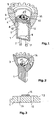
- FIGS. 1 to 3 and 6 a base GU10 lamp according to the invention is shown consisting of a lower part 1 with power supply 2, lampshade 3 and adhesive ceramic mounting substrate 4.
- FIG. 6 The lamp shown does not have a lampshade. Otherwise she is with the light of FIG. 1 identically formed.
- the mounting substrate 4 is in this example a support body or mounting plate for the LED and the driver 17 and consists in this example of gray fructiqueleitInBoxem AIN and the lampshade 3 of ruby-colored alumina with Chromoxiddot mich.
- the mounting substrate 4 is not visible.
- the lamp body or lampshade 3 is closed with a glass pane (not shown) at the upper end of the lampshade 3.
- sintered metallization regions 15 for soldering the LED (s) are arranged on the surface of the ceramic substrate 4. These sintered metallization regions 15 form conductor tracks and thus a circuit board. For reasons of clarity, the diodes on the metallization regions 15 are not shown.
- the drivers 17 are only schematic shown. In the embodiment shown, the drivers 17 are not arranged on the sintered metallization regions 14 or 15, but on the mounting substrate 4. With further miniaturization of the LED (2 * 2 mm are already possible today), the driver can also be mounted directly on the metallization regions 15 become.
- bushings 16 see FIG. 3
- plug elements (2, 11) are arranged for the electrical connection wires. These connecting wires are electrically conductively connected to the drivers 17 and the drivers 17 to the metallization regions 15.
- any number of metallization regions 15 may be arranged.
- the mounting substrate 4 has a radial indentation 13 on the circumferential surface facing the metallization region 15 for better fixation.
- the lamp is modularly formed from three ceramic parts, namely a lower part 1 with a power supply 2, a mounting substrate 4 or mounting plate and a lampshade 3.
- the power supply 2, 11 are, for example, electrical connection wires (not shown in FIG the figure) in the lower part 1 and within the lower part 1 to the drivers 17 and from there to the LEDs.
- the mounting substrate 4 consists of a ceramic with preferably a high heat dissipation. On the mounting substrate 4, the LED are soldered to the conductor tracks.
- the lampshade 3 is also preferably made of a ceramic with cooling fins 5 on its outer surface. The cooling fins 5 extend in the longitudinal direction of the lampshade third
- mounting substrate is the more general term, since the mounting substrate is only a mounting plate.
- the mounting substrate can also not be disc-shaped. Otherwise both terms describe the same item.
- the lower part 1 is formed cylindrically with an inner cavity 7. This saves material.
- the lamp thus consists of a lower part 1, a mounting plate 4 and a lampshade 3, which surrounds the LED. On the mounting substrate 4, the light source is attached.
- the lower part 1 can also be equipped as a plug for the production of plug-in connections with appropriate sockets or with threads for screwing in brackets or, in occupied with terminal poles sockets, in lamp holders.
- the lampshade 3 has on its circumference evenly distributed cooling fins 5, so that the outline of the lampshade 3 looks at its opening like a gear.
- the cooling fins 5 are, in particular in high-power LEDs, an advantage to dissipate the heat generated to the ambient air. Its cross section can take any other possible form such as semicircular or semi-elliptical. For LEDs with low heat losses, the screen can also be smooth. The screen may also have different shapes, such as oval or polygonal.
- the lower part 1 can also be formed integrally with the mounting substrate 4, this shows FIG. 2 ,
- FIG. 6 shows an embodiment of the luminaire according to FIG. 1 without lampshade 3. This screenless version is advantageous because heat and / or solar radiation directly (not shielded) affect the driver temperature and can be readjusted by this temperature change, the LEDs in no time. Same reference numerals in the FIGS. 1, 2 and 6 also show the same item.
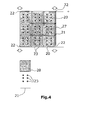
- FIG. 4 shows an array of 9 diode carriers 20, which consist of those in the WO 2007/107601 A2 (see description introduction) described ceramic heat sinks with sintered metallization regions as interconnects.
- diode carriers 20 On each diode support 20, 6 diodes or LEDs 23 are applied (shown only schematically) and electrically connected to each other via the metallization regions (not shown). For cooling, the diode carrier 20 on Finns 27.
- diode carriers 20 are shown. It can also be used any other form.
- the individual diode carrier 20 are installed or suspended in a metal frame 21, which also serves as a power supply for the LEDs 23 at the same time.
- the array of diode supports 20 is used for surface illumination, but can also be used for point illumination.
- the diode carrier 20 are fixed in different angles in the metal frame 21, that results in a focused light.
- the array can also be just for surface lighting or curved for a point lighting.
- the driver of the driving of the LEDs is also arranged on at least one, preferably on each diode carrier 20 at the same time. This is not shown in the figures.
- the sintered metallization regions are in this case formed as conductor tracks on which the LEDs are arranged.
- FIGS. 5a, 5b show a ceramic diode carrier 40 in supervision, FIG. 5a and on average, FIG. 5b , which consists of a ceramic support body 32, which is integrally provided with heat dissipating ceramic cooling elements 37, here fins, is provided.
- a ceramic support body 32 which is integrally provided with heat dissipating ceramic cooling elements 37, here fins, is provided.
- sintered metallization regions 41 are applied, so that the diode carrier 40 is a circuit board.
- LEDs 43 are attached, which are soldered onto the metallization 41.
- the diode carriers 40 have plugs and / or sockets as connecting elements with which the diode carriers 40 are connected directly or indirectly to each other.
- the plugs are pins 36, in particular according to the standard GU 5.3 and the sockets are adapted to the pins.
- FIG. 5 shows an embodiment with only connectors, which consist of pins 36 here. These pins 36, two for each plug, are located at the periphery of the diode carrier 40 with the plugs 36 on opposite sides of the diode carrier 40.
- a separate connecting element 38 is used here. This connecting element 38 is in the variant shown here a rectangular or square shaped plate with through holes 44. In these holes 44, the pins 36 on the diode support 40, establishing an electrical contact, plugged.
- each Connecting element 38 has four holes 44. Two holes 44 on the connecting element 38 are electrically connected to each other.
- the diode carriers 40 For fixing the diode carriers 40 in a frame, they have at least at one edge a strip 34 without metallization areas 41 and without LEDs 43 and drivers.
- This strip 34 thus forms a ceramic spring for attachment to a frame or a rail. At least two rails then form the frame.
- the strip 34 has at least one recess for attachment to preferably a screw.
- FIG. 7 shows in section and in an exploded view an alternative preferred embodiment of a lamp according to the invention.
- This lamp is similar to that of FIG. 1 and is intended for version E27.
- the lamp consists of six parts or units, namely a metallic threaded bush 52, a ceramic lower part 1, an electronic module 51 as a driver for driving the LEDs 43, a ceramic mounting substrate 4, a ceramic lampshade 3 with cooling fins 5 and a glass pane 50.
- the lower part 1 is formed as a hollow cylinder body open on both sides and is the central support body of the lamp. At its end facing away from the lampshade 3, the lower part 1 has an outer thread 54 radially retracted to the outer wall of the lower part 1. On this outer thread 54, the threaded bushing 52 is turned up with its inner thread. This threaded bush 52 is designed in accordance with standard E27 and consists of metal.
- the electronic module 51 is inserted, which contains the driver.
- the electrical connection of the electronic module 51 is only indicated for a better overview.
- the electronic module 51 is electrically connected to the LEDs 43 on the mounting substrate 4.
- the mounting substrate 4 two holes through which the electrical connection is made from the electronic module 51 to the LEDs.
- the ceramic mounting substrate 4 is glued to the lower part 1.
- the mounting substrate 4 is the support body or the mounting plate for the LEDs 43 and is preferably made of gray fructiqueleitInBoxem AIN and the lampshade 3 of ruby-colored aluminum oxide with Chromoxiddot mich.
- the mounting substrate 4 is not visible from the outside.
- the lampshade 3 is closed with a glass plate 50 at the upper end of the lampshade 3.
- the ceramic substrate 4 On the surface of the ceramic substrate 4, sintered metallization regions for soldering the LEDs 43 are arranged. These sintered metallization areas form conductor tracks and thus a circuit board.
- the drivers are arranged in the electronic module 51 on three vertically stacked printed circuit boards 51a, 51b, 51c. If space is sufficient, the drivers are preferably placed on the sintered metallization areas or on the bare mounting substrate 4. The drivers are electrically connected to the LED. Alternatively, the LEDs and the carrier body, i. H. the ceramic substrate 4, be electrically connected to each other via an electrically conductive intermediate layer.
- the drivers are arranged in the electronic module 51, which is located in the cavity 7 of the lower part 1.
- the electronic module 51 is fixed in the lower part 1 with a thermally conductive electrically insulating potting compound.
- the mounting substrate 4 may not be disc-shaped.
- the mounting substrate 4 has a radial intake 13 for better fixation.
- the mounting substrate 4 consists of a ceramic, preferably a high Heat dissipation.
- the LED are soldered to the conductor tracks.
- the lampshade 3 is preferably made of a ceramic with cooling fins 5 on its outer surface.
- the cooling fins 5 extend in the longitudinal direction of the lampshade third
- the lampshade 3 For better attachment of the lampshade 3 on the lower part 1, this has on its inner surface a paragraph 8, with which the lampshade 3 is seated on a corresponding paragraph or indentation 13 on the mounting substrate 4.
- the lower end of the lampshade 3 surrounds the mounting substrate 4 and the upper end 12 of the lower part 1.
- the lower part 1 is cylindrically formed with an inner cavity 7. This material is saved and there is space for the electronic module 51 created.
- the lower part 1 can also be equipped as a plug for the production of plug-in connections with appropriate sockets or with threads for screwing in brackets or, in occupied with terminal poles sockets, in lamp holders.
- the lampshade 3 has on its circumference evenly distributed in the longitudinal direction of the lamp extending cooling fins 5, so that the outline of the lampshade 3 looks at its opening like a gear.
- the cooling fins 5 are, in particular in high-power LEDs, an advantage to dissipate the heat generated to the ambient air. Its cross-section can also take any other possible form such as semicircular or semi-elliptic for example. For LEDs with low heat loss, the screen can also be smooth. The screen may also have different shapes, such as oval or polygonal.
- the electrical insulation is given and the driver can be connected directly without galvanic isolation. Due to the thermal heat conduction properties of the ceramic in conjunction with a thermally conductive potting compound and the spatially compact sandwich construction (see Figure. 7 ).
- the own power dissipation of the driver and the heat development through the LEDs come with a short time delay to the electronics, which then regulate the supply current of the LEDs so far linearly that a free predetermined maximum temperature of the entire system is not exceeded.
- the driver circuit itself, but also the LEDs are protected against overheating. The better the cooling, the brighter the LEDs shine and vice versa. Thermal overload is largely excluded.
- the entire circuit can be manually dimmed with commercial phase dimmers in a wide range.
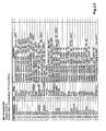
- FIG. 8 shows the complete electronic circuit of the drivers, being in the FIG. 14 the components used are listed.
- FIG. 9 shows the electronic circuit of the electronic module 51c (see FIG. 7 ).
- the FIGS. 12a and 13a show a schematic view of the electronic module 51c from above and below.
- the electronic module 51c is responsible for connection to the 230-volt network and has a bridge rectifier with diodes D2.
- the bridge rectifier is preceded by the two resistors R17 and R21 in order to avoid a short circuit in the case of discharged capacitors.
- the resistors R17 and R21 also serve as overvoltage protection for mains voltages up to 500 volts.
- the bridge of the bridge rectifier is provided with smoothing capacitors C1, C2 and C7, which are designed as ceramic capacitors and have a lifetime of up to 500,000 operating hours. With the capacitors and the coil L1 filtering is effected to short high noise frequencies.
- the capacitor C9 is an aluminum solid-state capacitor for dimming the generated DC voltage
- FIG. 10 shows the electronic circuit of the electronic module 51b (see FIG. 7 ).
- the Figures 12b and 13b show a schematic view of the electronic module 51b from above and below.
- the electronic module 51b is a dimming circuit for phase control dimming.
- the dimming circuit uses voltage dividers, diodes and MOS field-effect transistors.
- the dimming circuit simulates an ohmic load in the range of approx. 10 watts so that the power required for their operation is applied to the dimmers.
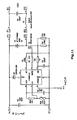
- FIG. 11 shows the electronic circuit of the electronic module 51a (see FIG. 7 ).
- the Figures 12c and 13c show a schematic view of the electronic module 51a from above and below.
- the electronic module 51a has an HV9961LG integrated circuit for controlling the output side LED current.
- a temperature-dependent resistor (NTC) R19 is arranged, which generates a temperature-dependent control signal for the integrated circuit for temperature-dependent activation of the LED.
- the temperature-dependent dimming is done using the pulse width modulation.
- the integrated circuit HV9961LG is designed for the military temperature range for temperatures from - 55 ° C to + 125 ° C with a power class of 10 watts to achieve a long service life.
- the integrated circuit Depending on the temperature, the integrated circuit generates a supply voltage for the LED which is reduced compared to the mains voltage, the remaining voltage being dissipated as heat.
- the integrated circuit On the output side, the integrated circuit is provided with a MOS field-effect transistor Q1 and with a choke coil L2 with an inductance of 3 millihenries. With the control circuit according to Fig. 11 can be operated up to 8 LEDs.
Landscapes
- Engineering & Computer Science (AREA)
- General Engineering & Computer Science (AREA)
- Microelectronics & Electronic Packaging (AREA)
- Physics & Mathematics (AREA)
- Optics & Photonics (AREA)
- Arrangement Of Elements, Cooling, Sealing, Or The Like Of Lighting Devices (AREA)
- Led Device Packages (AREA)
- Non-Portable Lighting Devices Or Systems Thereof (AREA)
- Circuit Arrangement For Electric Light Sources In General (AREA)
- Fastening Of Light Sources Or Lamp Holders (AREA)
Applications Claiming Priority (5)
| Application Number | Priority Date | Filing Date | Title |
|---|---|---|---|
| DE102010042485 | 2010-10-15 | ||
| DE102011012672 | 2011-01-07 | ||
| DE102011008065 | 2011-01-07 | ||
| DE102011016502 | 2011-04-08 | ||
| EP11773230.5A EP2628359A1 (fr) | 2010-10-15 | 2011-10-14 | Lampe à led à pilote intégré |
Related Parent Applications (1)
| Application Number | Title | Priority Date | Filing Date |
|---|---|---|---|
| EP11773230.5A Division EP2628359A1 (fr) | 2010-10-15 | 2011-10-14 | Lampe à led à pilote intégré |
Publications (1)
| Publication Number | Publication Date |
|---|---|
| EP2734012A1 true EP2734012A1 (fr) | 2014-05-21 |
Family
ID=45440483
Family Applications (2)
| Application Number | Title | Priority Date | Filing Date |
|---|---|---|---|
| EP13195218.6A Withdrawn EP2734012A1 (fr) | 2010-10-15 | 2011-10-14 | Lampe à LED avec pilote intégré |
| EP11773230.5A Withdrawn EP2628359A1 (fr) | 2010-10-15 | 2011-10-14 | Lampe à led à pilote intégré |
Family Applications After (1)
| Application Number | Title | Priority Date | Filing Date |
|---|---|---|---|
| EP11773230.5A Withdrawn EP2628359A1 (fr) | 2010-10-15 | 2011-10-14 | Lampe à led à pilote intégré |
Country Status (11)
| Country | Link |
|---|---|
| US (1) | US20130241426A1 (fr) |
| EP (2) | EP2734012A1 (fr) |
| JP (1) | JP2013545225A (fr) |
| KR (1) | KR20140027057A (fr) |
| CN (1) | CN103238372A (fr) |
| BR (1) | BR112013009194A2 (fr) |
| DE (1) | DE102011114882A1 (fr) |
| PH (1) | PH12013500728A1 (fr) |
| RU (1) | RU2013121971A (fr) |
| TW (1) | TW201229427A (fr) |
| WO (1) | WO2012049284A1 (fr) |
Families Citing this family (10)
| Publication number | Priority date | Publication date | Assignee | Title |
|---|---|---|---|---|
| US20140131742A1 (en) * | 2012-11-12 | 2014-05-15 | Andrey Zykin | LED Spirit Connector System and Manufacturing Method |
| JP5971163B2 (ja) * | 2013-03-19 | 2016-08-17 | 東芝ライテック株式会社 | 照明装置 |
| EP2833701B1 (fr) * | 2013-07-29 | 2020-01-22 | Tridonic GmbH & Co KG | Circuit de commande intégré avec détection combinée de présence et de température |
| JP6444090B2 (ja) * | 2014-08-01 | 2018-12-26 | キヤノン株式会社 | 整流平滑回路、電源装置及び画像形成装置 |
| DE102014110994A1 (de) * | 2014-08-01 | 2016-02-04 | Seidel GmbH & Co. KG | Leuchtvorrichtung mit einem Anschlussmodul |
| US9709249B2 (en) * | 2014-10-08 | 2017-07-18 | Checkers Industrial Products, Llc | Arrow board light and touch controller |
| US10317015B2 (en) * | 2015-08-19 | 2019-06-11 | Auroralight, Inc. | Light module with self-aligning electrical and mechanical connection |
| US20190346086A1 (en) * | 2015-08-19 | 2019-11-14 | Michael Joye | Light module with self-aligning electrical and mechanical connection |
| KR101683624B1 (ko) | 2015-11-12 | 2016-12-21 | (주)프리모 | 차량용 led 램프 |
| IT202000015706A1 (it) * | 2020-06-30 | 2021-12-30 | Ultrasuono Service S R L | Lampada led per proiettore di veicolo |
Citations (7)
| Publication number | Priority date | Publication date | Assignee | Title |
|---|---|---|---|---|
| DE202005006053U1 (de) * | 2005-04-15 | 2005-06-30 | Wieland, Friedrich Wilhelm | Energiesparlampe |
| WO2007107601A2 (fr) | 2006-03-23 | 2007-09-27 | Ceramtec Ag | Élément support pour composants ou circuits |
| US20080258647A1 (en) * | 2004-05-19 | 2008-10-23 | Goeken Group Corp. | Dimming Circuit for Led Lighting Device With Means for Holding Triac in Conduction |
| US20100096993A1 (en) * | 2004-11-29 | 2010-04-22 | Ian Ashdown | Integrated Modular Lighting Unit |
| US20100103678A1 (en) * | 2008-10-24 | 2010-04-29 | Cree Led Lighting Solutions, Inc. | Lighting device, heat transfer structure and heat transfer element |
| US20100155766A1 (en) * | 2008-12-22 | 2010-06-24 | Foxconn Technology Co., Ltd. | Light emitting diode and method for manufacturing the same |
| US20100213469A1 (en) * | 2009-02-24 | 2010-08-26 | Andrew Locke | Illumination device |
Family Cites Families (8)
| Publication number | Priority date | Publication date | Assignee | Title |
|---|---|---|---|---|
| CN101142856A (zh) * | 2004-11-29 | 2008-03-12 | Tir技术有限公司 | 集成模块化照明单元 |
| WO2006056066A1 (fr) * | 2004-11-29 | 2006-06-01 | Tir Systems Ltd. | Unite d'eclairage modulaire integree |
| JP3978451B2 (ja) * | 2005-07-27 | 2007-09-19 | 京セラ株式会社 | 発光装置 |
| US7550319B2 (en) * | 2005-09-01 | 2009-06-23 | E. I. Du Pont De Nemours And Company | Low temperature co-fired ceramic (LTCC) tape compositions, light emitting diode (LED) modules, lighting devices and method of forming thereof |
| JP4724700B2 (ja) * | 2007-10-19 | 2011-07-13 | 株式会社Maruwa | 発光装置 |
| US20090296387A1 (en) * | 2008-05-27 | 2009-12-03 | Sea Gull Lighting Products, Llc | Led retrofit light engine |
| JP5451990B2 (ja) * | 2008-06-20 | 2014-03-26 | シャープ株式会社 | 照明装置 |
| JP4406854B2 (ja) * | 2009-06-24 | 2010-02-03 | 東芝ライテック株式会社 | 発光素子ランプ及び照明器具 |
-
2011
- 2011-10-05 DE DE102011114882A patent/DE102011114882A1/de not_active Withdrawn
- 2011-10-14 CN CN2011800597854A patent/CN103238372A/zh active Pending
- 2011-10-14 EP EP13195218.6A patent/EP2734012A1/fr not_active Withdrawn
- 2011-10-14 RU RU2013121971/07A patent/RU2013121971A/ru not_active Application Discontinuation
- 2011-10-14 WO PCT/EP2011/067962 patent/WO2012049284A1/fr not_active Ceased
- 2011-10-14 EP EP11773230.5A patent/EP2628359A1/fr not_active Withdrawn
- 2011-10-14 TW TW100137277A patent/TW201229427A/zh unknown
- 2011-10-14 BR BR112013009194A patent/BR112013009194A2/pt not_active IP Right Cessation
- 2011-10-14 US US13/879,098 patent/US20130241426A1/en not_active Abandoned
- 2011-10-14 KR KR1020137012451A patent/KR20140027057A/ko not_active Withdrawn
- 2011-10-14 PH PH1/2013/500728A patent/PH12013500728A1/en unknown
- 2011-10-14 JP JP2013533229A patent/JP2013545225A/ja active Pending
Patent Citations (7)
| Publication number | Priority date | Publication date | Assignee | Title |
|---|---|---|---|---|
| US20080258647A1 (en) * | 2004-05-19 | 2008-10-23 | Goeken Group Corp. | Dimming Circuit for Led Lighting Device With Means for Holding Triac in Conduction |
| US20100096993A1 (en) * | 2004-11-29 | 2010-04-22 | Ian Ashdown | Integrated Modular Lighting Unit |
| DE202005006053U1 (de) * | 2005-04-15 | 2005-06-30 | Wieland, Friedrich Wilhelm | Energiesparlampe |
| WO2007107601A2 (fr) | 2006-03-23 | 2007-09-27 | Ceramtec Ag | Élément support pour composants ou circuits |
| US20100103678A1 (en) * | 2008-10-24 | 2010-04-29 | Cree Led Lighting Solutions, Inc. | Lighting device, heat transfer structure and heat transfer element |
| US20100155766A1 (en) * | 2008-12-22 | 2010-06-24 | Foxconn Technology Co., Ltd. | Light emitting diode and method for manufacturing the same |
| US20100213469A1 (en) * | 2009-02-24 | 2010-08-26 | Andrew Locke | Illumination device |
Also Published As
| Publication number | Publication date |
|---|---|
| DE102011114882A1 (de) | 2012-04-19 |
| EP2628359A1 (fr) | 2013-08-21 |
| RU2013121971A (ru) | 2014-11-20 |
| US20130241426A1 (en) | 2013-09-19 |
| WO2012049284A1 (fr) | 2012-04-19 |
| TW201229427A (en) | 2012-07-16 |
| CN103238372A (zh) | 2013-08-07 |
| JP2013545225A (ja) | 2013-12-19 |
| KR20140027057A (ko) | 2014-03-06 |
| PH12013500728A1 (en) | 2013-07-08 |
| BR112013009194A2 (pt) | 2016-07-26 |
Similar Documents
| Publication | Publication Date | Title |
|---|---|---|
| EP2628358A1 (fr) | Circuit pilote de led | |
| EP2734012A1 (fr) | Lampe à LED avec pilote intégré | |
| CH698769A2 (de) | Montageanordnung eines Leuchtkörpers. | |
| DE102010008876A1 (de) | Lichtquelle mit Array-LEDs zum direkten Betrieb am Wechselspannungsnetz | |
| DE112013001316T5 (de) | LED-Anordnung für den Ersatz von Leuchtstoffröhren | |
| DE102010026344A1 (de) | Leuchtdiode | |
| DE102010052020A1 (de) | Haltekörper zur Aufnahme von mindestens einem Leuchtmittel sowie Beleuchtungs- und/oder Anzeigenvorrichtung | |
| DE202013000980U1 (de) | "LED-Retrofit-Lampe" | |
| DE102015102081A1 (de) | Licht emittierende vorrichtung und verfahren zum betreiben mehrerer licht emittierender anordnungen | |
| EP2580946B1 (fr) | Agencement de diode luminescente et élément lumineux comprenant notamment un tel agencement de diode luminescente | |
| DE102014106778A1 (de) | Lichtquellen-Treibervorrichtung und Lichtquellensystem | |
| DE102013110257A1 (de) | LED-Lampe | |
| DE112016002778T5 (de) | Modulare integrierte Beleuchtungsschaltung | |
| DE112016002776T5 (de) | Low-Profile-Deckenleuchte | |
| DE102011006749A1 (de) | Lampenvorrichtung | |
| DE102020111798B4 (de) | Treiberschaltung für Beleuchtungsmittel, Lampe und Verfahren zum Betreiben einer Lampe | |
| WO2009037544A2 (fr) | Lampe électrique comportant une diode luminescente et un réflecteur de lampe | |
| DE112016002779T5 (de) | Magnetfreie LED-Licht-Engine mit hoher Leistung und Low-profile-Design | |
| DE112016002781T5 (de) | Low-profile-Klemme | |
| EP2504615A1 (fr) | Lampe à led munie d'un culot à broches pour lampes halogènes ('bipin') | |
| DE102017106959A1 (de) | Leuchtvorrichtung und Leuchtsystem | |
| DE102011114253A1 (de) | Leuchtvorrichtung | |
| DE202009017433U1 (de) | LED-Leuchte mit Kühlkörper |
Legal Events
| Date | Code | Title | Description |
|---|---|---|---|
| PUAI | Public reference made under article 153(3) epc to a published international application that has entered the european phase |
Free format text: ORIGINAL CODE: 0009012 |
|
| 17P | Request for examination filed |
Effective date: 20131202 |
|
| AC | Divisional application: reference to earlier application |
Ref document number: 2628359 Country of ref document: EP Kind code of ref document: P |
|
| AK | Designated contracting states |
Kind code of ref document: A1 Designated state(s): AL AT BE BG CH CY CZ DE DK EE ES FI FR GB GR HR HU IE IS IT LI LT LU LV MC MK MT NL NO PL PT RO RS SE SI SK SM TR |
|
| 17Q | First examination report despatched |
Effective date: 20140520 |
|
| RBV | Designated contracting states (corrected) |
Designated state(s): AL AT BE BG CH CY CZ DE DK EE ES FI FR GB GR HR HU IE IS IT LI LT LU LV MC MK MT NL NO PL PT RO RS SE SI SK SM TR |
|
| STAA | Information on the status of an ep patent application or granted ep patent |
Free format text: STATUS: THE APPLICATION IS DEEMED TO BE WITHDRAWN |
|
| 18D | Application deemed to be withdrawn |
Effective date: 20180501 |