EP2734407B1 - Ferrure dotée d'un adaptateur bloquant axialement une partie de ferrure - Google Patents
Ferrure dotée d'un adaptateur bloquant axialement une partie de ferrure Download PDFInfo
- Publication number
- EP2734407B1 EP2734407B1 EP12727800.0A EP12727800A EP2734407B1 EP 2734407 B1 EP2734407 B1 EP 2734407B1 EP 12727800 A EP12727800 A EP 12727800A EP 2734407 B1 EP2734407 B1 EP 2734407B1
- Authority
- EP
- European Patent Office
- Prior art keywords
- fitting
- fitting part
- collar
- adapter plate
- radial direction
- Prior art date
- Legal status (The legal status is an assumption and is not a legal conclusion. Google has not performed a legal analysis and makes no representation as to the accuracy of the status listed.)
- Active
Links
Images


Classifications
-
- B—PERFORMING OPERATIONS; TRANSPORTING
- B60—VEHICLES IN GENERAL
- B60N—SEATS SPECIALLY ADAPTED FOR VEHICLES; VEHICLE PASSENGER ACCOMMODATION NOT OTHERWISE PROVIDED FOR
- B60N2/00—Seats specially adapted for vehicles; Arrangement or mounting of seats in vehicles
- B60N2/02—Seats specially adapted for vehicles; Arrangement or mounting of seats in vehicles the seat or part thereof being movable, e.g. adjustable
- B60N2/22—Seats specially adapted for vehicles; Arrangement or mounting of seats in vehicles the seat or part thereof being movable, e.g. adjustable the back-rest being adjustable
- B60N2/225—Seats specially adapted for vehicles; Arrangement or mounting of seats in vehicles the seat or part thereof being movable, e.g. adjustable the back-rest being adjustable by cycloidal or planetary mechanisms
- B60N2/2252—Seats specially adapted for vehicles; Arrangement or mounting of seats in vehicles the seat or part thereof being movable, e.g. adjustable the back-rest being adjustable by cycloidal or planetary mechanisms in which the central axis of the gearing lies inside the periphery of an orbital gear, e.g. one gear without sun gear
-
- B—PERFORMING OPERATIONS; TRANSPORTING
- B60—VEHICLES IN GENERAL
- B60N—SEATS SPECIALLY ADAPTED FOR VEHICLES; VEHICLE PASSENGER ACCOMMODATION NOT OTHERWISE PROVIDED FOR
- B60N2/00—Seats specially adapted for vehicles; Arrangement or mounting of seats in vehicles
- B60N2/68—Seat frames
- B60N2/682—Joining means
Definitions
- the invention relates to a fitting, in particular a Lehneneinstellbeschlag for a vehicle seat, in particular for a motor vehicle seat, with a first disk-shaped fitting part on which a ring gear is formed, and a rotatable relative to the first fitting part about a rotational axis of the fitting second disc-shaped fitting part on which a spur gear is formed, which meshes with the ring gear, whereby the two fitting parts are in gear connection with each other, and a rotatably mounted, driven by a cam, rotating eccentric means for driving a relative rolling movement of spur gear and ring gear.
- the publication DE 20 2009 007 513 U1 discloses a fitting for a vehicle seat with a first fitting part on which a sprocket is formed and a second fitting part on which a gear is formed.
- the gear meshes with the ring gear, whereby the two fitting parts are in gear connection with each other.
- the fitting further comprises a rotatably mounted, driven by a driver, rotating eccentric for driving a relative rolling gear and ring gear, wherein the two fitting parts together form a disk-shaped, held together by a Umklamm réellesring unit in structural terms.
- the first fitting part and the Umklamm réellesring are connected to each other and take the second fitting part between them.
- the ring gear is fixedly formed on the Umklamm réellesring connected to the first fitting part.
- the connection between the first fitting part and the Umklamm ceremoniessring is made by welding to form a weld.
- the weld between the first fitting part and the Umklamm réellesring is generated from a radial direction, for example by means of laser welding.
- a weld between the first fitting and the Umklamm réellesring also preferably produced by laser welding from an axial direction.
- the Umklamm réellesring protects the gear and causes under inclusion of axially acting forces the cohesion of the fitting parts in the axial direction, as from the in the document DE 20 2009 007 513 U1 mentioned document DE 10 2006 044 490 A1 evident.
- To secure the fittings and to connect the Fitting parts to the respective seat structure is disadvantageously required a variety of components.
- the publication DE 29 18 252 A1 teaches a hinge fitting for seats with adjustable backrest, in which a fixed joint part assigned to the seat and a pivotable joint part assigned to the backrest and a pivotable joint part assigned to the backrest and a pivotable joint part assigned to the backrest are connected to one another via a pivot axis.
- the hinge fitting also has a the position of the two joint parts to each other determining locking and locking device.
- a hinge part is associated with an inner ring gear and arranged on the pivotable axis, provided by a handle rotatable eccentric.
- the other joint part is assigned an inner ring gear, which forms a row of teeth with the inner ring gear of a joint part by different numbers of teeth of the two sprockets.
- the inner space of the inner sprockets of the joint parts is provided with a respective bridging, in which the bearing is arranged for the eccentric shaft of the eccentric.
- Each bridging is secured to the respectively associated joint part by means of a welded joint.
- the bridges are welded directly to the seat structure (seat part and backrest). With regard to a simple fitting of fitting and vehicle seat, direct welding to the seat structure is considered disadvantageous.
- the publication DE 10 2007 009 172 B4 describes a fitting for a vehicle seat, with a first fitting part and with a relative to the first fitting part rotatable about an axis second fitting part and the two fitting parts in the axial direction cohesive ring, whereby the fitting forms a disc-shaped unit.
- An adapter is provided, which rests on the first fitting part, in particular on impact, and which defines a connection surface by the system on the first fitting part and which is connected by means of a weld with the first fitting part and / or the ring.
- the document discloses that the weld is generated from a direction which extends within the joint surface or at a shallow angle of up to + 25 ° to the joint surface.
- the fitting is characterized in one embodiment in that the first fitting part, the ring and the adapter are connected to each other by means of the weld. It is proposed to generate the weld by a laser beam or electron beam which aims at the impact between the adapter and the first fitting part from the direction within the connecting surface or at the shallow angle thereto. Also in this solution are disadvantageously to secure the fittings and the connection the fitting parts to the respective seat structure (seat part and backrest) requires many components to be joined together.
- the invention is based on the object to provide a weight and material-saving and secure fitting.
- the preamble corresponding fitting comprises a first disk-shaped fitting part on which a ring gear is formed, and a relative to the first fitting part about a rotational axis of the fitting rotatable second disc-shaped fitting on which a spur gear is formed, which meshes with the ring gear, whereby the two fittings are geared together.
- the fitting further comprises a rotatably mounted, driven by a cam, rotating eccentric means for driving a relative rolling movement of spur gear and ring gear.
- the fitting also has the first fitting part a collar which overlaps the second fitting part and which forms an offset with respect to the first fitting part in the axial direction of the fitting, the collar of the first fitting part being connected to a first adapter plate via its surfaces facing each other in the axial direction of the fitting Connection stands.
- the first adapter plate is disposed in an axial gap, which is formed by the second fitting part and a second adapter plate, so that by the connection of the first fitting part with the first Adapter plate and by the second fitting part cross-collar of the first fitting part axial securing of lying between the first adapter plate and the first fitting part second fitting part is effected.
- the collar of the first fitting part is in communication with the first adapter plate and by the collar over the second fitting part achieved that the second fitting part is axially secured, since the second fitting part between the adapter plate and the first fitting part, which is why an additional axial securing of the first and second fitting part is eliminated.
- the first fitting part cup-shaped, designed in the manner of a "U".
- the offset of the collar forms with respect to the disc of the first fitting part an edge, whereby the second fitting part rests in the plane of the collar in the U-shaped first fitting part.
- the formed in the radial direction of internal teeth of the ring gear of the first fitting part is formed on the also lying in the radial direction inside of the collar and engages the external teeth of the spur gear of the second fitting part, whereby the two fitting parts on the in the radial direction facing each other inside the collar - with the internal teeth of the ring gear - the first fitting part and the front side - with the external teeth of the spur gear - the second fitting part are in gearbox connection with each other.
- the result is a compact, stable and quickly and thus efficiently adjustable fitting, which is essentially composed of two kinematic units whose components are laser welded together.
- the respective adapter plate allows the fitting to be easily connected to the structure of the seat part or with the structure of the backrest of a vehicle seat.
- On the size and shape of the respective adapter plate in particular a simple adaptation of a fitting to different vehicle seats in a simple manner possible.
- the connection of the components of the two kinematic units by means of a welded joint represents a particularly stable and high forces receiving connection, whereby the axial securing of the second fitting part is stable and durable to produce.
- FIG. 1 shows in a sectional view, transverse to the axis of rotation / pivot axis Y a possible construction of a fitting, in particular a Lehneneinstellbeschlages 10th
- Lehneneinstellbeschlag 10 has a connected to the seat part fixed, second fitting part 12 and connected to the backrest, relative to the second fitting part 12 adjustable, first fitting part 11, the are connected by the eccentric 14 comprehensive pivot axis Y together, which are part of a trained as a gear locking and locking device.
- To this transmission includes an example formed by stamping out of the second fitting part 12 spur gear 15 with external teeth 16 which meshes with the internal teeth 18 of a ring gear 17, for example, also formed by stamping out of the first fitting part 11.
- the diameter of the top circle of the external toothing 16 is smaller by at least one tooth height than the diameter of the root circle of the internal toothing 18. Accordingly, the toothings 16 and 18 have tooth numbers which differ by at least one tooth, the number of teeth of the internal toothing 18 being greater than that Number of teeth of the external toothing 16.
- the arrangement shown is chosen such that the external toothing 16 can roll on the internal toothing 18.
- the first fitting part 11 Concentric with its internal toothing 18, the first fitting part 11 has a first collar pull 19, in which a driver 20 designed as a sleeve is mounted.
- This preferably made of plastic usually integrally formed driver 20 includes a hub 21 which is rotatably supported with its outer shell in the first collar 19 of the first fitting part 11, wherein the hub 21, a collar portion 19 partially cross-section and at a radial distance from the hub 21 arranged Mit Economicsarm 22 is connected, in turn, as well as the hub 21 on the outside of the fitting 10 in the transmission area cross-cover (not shown) passes.
- Lehneneinstellbeschlages 10 The described detailed description of the structure of Lehneneinstellbeschlages 10 is for understanding.
- the responsible in Figure for the drive of Lehneneinstellbeschlages 10 components 20, 21, 22, 24, 26 represent only a specific embodiment of the Lehneneinstellbeschlages 10 shown by way of example.
- the ring gear 11 of the first fitting part and the spur gear 12 of the second fitting part are considered, as will be explained in more detail below.
- the fitting parts 11, 12 are connected in a particularly advantageous manner, each with an adapter plate 11A, 12A.
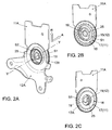
- FIG. 2A shows a perspective view of Lehneneinstellbeschlages 10 - from the left - showing a first, upper and a second, lower adapter plate 11A, 12A. Seen from left to right along the axis of rotation Y in the axial direction A is the first, the second, lower adapter plate 12A is arranged, which is fixedly connected to the seat part of a vehicle seat. An end face of the second collar 25 is visible. On the second collar 25 of the second fitting part 12 is the second, lower adapter plate 12A. The second, lower adapter plate 12A has in this area a material thickness which corresponds approximately to the width of the second collar 25.
- first, upper adapter plate 11A Behind the first, upper adapter plate 11A, an end face of a first weld S1 is visible, to which an end face of a collar 17A of the first fitting part 11 adjoins.
- the first, upper adapter plate 11A and the collar 17A of the first fitting part 11 are welded together by their axial direction A of Lehneneinstellbeschlages 10 facing each other from the radial direction R with each other. Together they form a kinematic unit 11, 11A, 17A.
- FIG. 2B shows a perspective view of Lehneneinstellbeschlages 10 - from the left - showing the first, upper adapter plate 11 A, in which the second, lower adapter plate 12 A has been omitted.
- the second collar 25 is visible.
- the spur gear 15 of the second fitting part 12 with its external teeth 16 and the ring gear 17 of the first fitting part 11 with its internal teeth 18 visible.
- the first collar part 19 belonging to the first fitting part 11 is in both FIGS. 2A, 2B equally visible.
- Figure 2C shows a perspective view of Lehneneinstellbeschlages 10 - from the right - showing the first, upper adapter plate 11A.
- the view from the right, so to speak, shows the back of Lehneneinstellbeschlages 10, which is visible again seen in the spur gear 15 of the second fitting part 12 and the ring gear 17 of the first fitting part 11 from the back. Visible is also the collar 17A of the first fitting part 11, which is connected via the lying in the radial direction R first weld S1 with the first, upper adapter plate 11A.
- FIG. 3A shows to further illustrate the construction of Lehneneinstellbeschlages 10 a section through the Lehneneinstellbeschlag 10th
- the cut of the FIG. 3A by a Lehneneinstellbeschlag 10 illustrates once again the position of the components to each other.
- the second kinematic unit from the second fitting part 12 and the second, lower adapter plate 12A is produced via the second weld S2, which is made on the second collar 25 of the second fitting part 12 in the axial direction A lying.
- the second fitting part 12 and the second, lower adapter plate 12A form an axial gap in which the first upper adapter plate 11A fits.
- the adapter plates 11A, 12A firmly welded to the fitting parts 11, 12 are movable relative to each other during a relative movement of the fitting parts 11, 12 in the case of a backrest adjustment.
- the first kinematic unit of the first fitting part 11 and the first, upper adapter plate 11A is produced via the first weld S1, wherein the first, upper adapter plate and the collar 17A via their in the axial direction A of Lehneneinstellbeschlages 10 facing each other from the radial direction R. welded together.
- FIG. 3B shows an enlarged view of a portion of the sectional view FIG. 3A , In particular in FIG. 3B is visible that the collar 17A of the first fitting part 11, the second fitting part 12, in particular the spur gear 15 of the second fitting part in the axial direction A overlaps.
- the collar 17A forms with respect to the disc of the first fitting part 11 an axial offset 17B, which in FIG. 3B in the region of the spur gear 15 of the second fitting part 12 is applied.
- this offset 17B creates a U-shaped first fitting part 11 with a pot-like edge.
- this pot is the disc of the second fitting part 12, which can be arranged by the cup-like design of the first fitting part 11 in the same plane as the collar 17A of the first fitting part eleventh
- the offset 17 B of the collar 17 is formed so that it substantially corresponds to the width of the disc of the second fitting part 12, it being ensured that sufficient axial play between the first and second fitting part 11, 12 and the second fitting part 12 and the first, upper adapter plate 11A of the first fitting part 11 consists.
- FIG. 3B illustrates in the enlarged view how the second fitting part 12 between the first, upper adapter plate 11A and the disc of the first fitting part 11 is axially secured.
- the collar 17A is welded to the first, upper adapter plate 11A and secures the second fitting part 12 in the axial direction A.
Landscapes
- Engineering & Computer Science (AREA)
- Aviation & Aerospace Engineering (AREA)
- Transportation (AREA)
- Mechanical Engineering (AREA)
- Chairs For Special Purposes, Such As Reclining Chairs (AREA)
Claims (7)
- Ferrure pour un siège de véhicule, comprenant une première partie de ferrure en forme de disque (11) au niveau de laquelle est réalisée une couronne dentée creuse (17) et une deuxième partie de ferrure en forme de disque (12) pouvant tourner par rapport à la première partie de ferrure (11) autour d'un axe de rotation (Y) de la ferrure, au niveau de laquelle est réalisée une roue dentée frontale (15) qui s'engrène avec la couronne dentée creuse (17) de telle sorte que les deux parties de ferrure (11, 12) soient en liaison d'engrènement l'une avec l'autre et un moyen excentrique en rotation (14), supporté de manière rotative et entraîné par un dispositif d'entraînement (20) pour l'entraînement d'un mouvement de roulement relatif de la roue dentée frontale (15) et de la couronne dentée creuse (17), la première partie de ferrure (11) présentant une bride (17A) venant en prise pardessus la deuxième partie de ferrure (12), qui forme par rapport à la première partie de ferrure (11), dans la direction axiale (A) de la ferrure, un gradin (17B), la bride (17A) de la première partie de ferrure (11) étant en liaison avec une première plaque d'adaptateur (11A) de la première partie de ferrure (11) par le biais de ses surfaces tournées l'une vers l'autre dans la direction axiale (A) de la ferrure, caractérisée en ce que la première plaque d'adaptateur (11A) est disposée dans un espace intermédiaire axial qui est formé par la deuxième partie de ferrure (12) et une deuxième plaque d'adaptateur (12A) de la deuxième partie de ferrure (12) de telle sorte qu'une fixation axiale de la deuxième partie de ferrure (12) située entre la première plaque d'adaptateur (11A) et la première partie de ferrure (11) puisse être réalisée par la connexion de la première partie de ferrure (11) à la première plaque d'adaptateur (11A) et par la bride (17A) de la première partie de ferrure (11) venant en prise par le dessus avec la deuxième partie de ferrure (12).
- Ferrure selon la revendication 1, caractérisée en ce que la première partie de ferrure (11) est réalisée en forme de pot, à la manière d'un "U", le gradin axial (17B) de la bride (17A) formant par rapport au disque de la première partie de ferrure (11) un bord de la première partie de ferrure en forme de pot (11), de telle sorte que la deuxième partie de ferrure (12) s'insère dans le plan de la bride (17A) dans la première partie de ferrure en forme de U (11).
- Ferrure selon la revendication 1, caractérisée en ce que la première plaque d'adaptateur (11A) et la bride (17A) de la première partie de ferrure (11) sont soudées l'une à l'autre par le biais de leurs surfaces tournées l'une vers l'autre dans la direction axiale (A) de la ferrure à partir de la direction radiale (R) et forment une première unité cinématique (11, 11A, 17A) par la connexion réalisée par le biais d'un premier joint de soudure (S1).
- Ferrure selon la revendication 3, caractérisée en ce que la première plaque d'adaptateur (11A) et la bride (17A) de la première partie de ferrure (11) sont soudées au laser l'une à l'autre par le biais de leurs surfaces tournées l'une vers l'autre dans la direction axiale (A) de la ferrure à partir de la direction radiale (R).
- Ferrure selon la revendication 1, caractérisée en ce que la denture interne (18) de la couronne dentée creuse (17) de la première partie de ferrure (11) réalisée dans la direction radiale (R) est réalisée sur le côté intérieur de la bride (17A) situé dans la direction radiale (R) et vient en prise dans la denture extérieure (16) de la roue dentée frontale (15) de la deuxième partie de ferrure (12) opposée disposée également dans la direction radiale (R), de sorte que les deux parties de ferrure (11, 12) sont en liaison d'engrènement l'une avec l'autre.
- Ferrure selon la revendication 1, caractérisée en ce que la deuxième plaque d'adaptateur (12A) et une deuxième bride saillante (25) de la deuxième partie de ferrure (12) sont soudées l'une à l'autre par le biais de leurs surfaces tournées l'une vers l'autre dans la direction radiale (R) de la ferrure à partir de la direction axiale (A) et forment une deuxième unité cinématique (12, 12A, 25) par la connexion réalisée par le biais d'un deuxième joint de soudure (S2).
- Ferrure selon la revendication 1, caractérisée en ce que la deuxième plaque d'adaptateur (12A) et une deuxième bride saillante (25) de la deuxième partie de ferrure (12) sont soudées au laser l'une à l'autre par le biais de leurs surfaces tournées l'une vers l'autre dans la direction radiale (R) de la ferrure à partir de la direction axiale (A).
Applications Claiming Priority (2)
| Application Number | Priority Date | Filing Date | Title |
|---|---|---|---|
| DE102011107997A DE102011107997A1 (de) | 2011-07-19 | 2011-07-19 | Beschlag mit einem ein Beschlagteil axial sichernden Adapter |
| PCT/EP2012/002472 WO2013010609A1 (fr) | 2011-07-19 | 2012-06-11 | Ferrure dotée d'un adaptateur bloquant axialement une partie de ferrure |
Publications (3)
| Publication Number | Publication Date |
|---|---|
| EP2734407A1 EP2734407A1 (fr) | 2014-05-28 |
| EP2734407B1 true EP2734407B1 (fr) | 2016-08-10 |
| EP2734407B8 EP2734407B8 (fr) | 2022-01-19 |
Family
ID=46317337
Family Applications (1)
| Application Number | Title | Priority Date | Filing Date |
|---|---|---|---|
| EP12727800.0A Active EP2734407B8 (fr) | 2011-07-19 | 2012-06-11 | Ferrure dotée d'un adaptateur bloquant axialement une partie de ferrure |
Country Status (5)
| Country | Link |
|---|---|
| EP (1) | EP2734407B8 (fr) |
| CN (1) | CN103648838B (fr) |
| DE (1) | DE102011107997A1 (fr) |
| PL (1) | PL2734407T3 (fr) |
| WO (1) | WO2013010609A1 (fr) |
Family Cites Families (7)
| Publication number | Priority date | Publication date | Assignee | Title |
|---|---|---|---|---|
| DE2918252A1 (de) | 1979-05-05 | 1980-11-20 | Rentrop Hubbert & Wagner | Gelenkbeschlag fuer sitze mit verstellbarer lehne, insbesondere kraftfahrzeugsitze |
| DE10305407B4 (de) * | 2003-02-11 | 2006-11-02 | Keiper Gmbh & Co.Kg | Getriebebeschlag für einen Fahrzeugsitz |
| DE102006044490B4 (de) | 2006-01-24 | 2008-08-28 | Keiper Gmbh & Co.Kg | Beschlag für einen Fahrzeugsitz |
| DE102007009172B4 (de) | 2007-02-21 | 2009-05-07 | Keiper Gmbh & Co. Kg | Beschlag für einen Fahrzeugsitz |
| CN102046413B (zh) * | 2008-06-13 | 2013-06-05 | 布罗斯尔汽车零件科堡两合公司 | 调整配件 |
| DE102009011462B4 (de) | 2009-02-27 | 2022-08-25 | Keiper Seating Mechanisms Co., Ltd. | Beschlag für einen Fahrzeugsitz und Fahrzeugsitz |
| DE102010035442B4 (de) * | 2010-08-23 | 2013-01-31 | Keiper Gmbh & Co. Kg | Verfahren zum Verbinden eines Beschlags mit einem Strukturteil eines Fahrzeugsitzes |
-
2011
- 2011-07-19 DE DE102011107997A patent/DE102011107997A1/de not_active Withdrawn
-
2012
- 2012-06-11 CN CN201280035817.1A patent/CN103648838B/zh active Active
- 2012-06-11 PL PL12727800T patent/PL2734407T3/pl unknown
- 2012-06-11 EP EP12727800.0A patent/EP2734407B8/fr active Active
- 2012-06-11 WO PCT/EP2012/002472 patent/WO2013010609A1/fr not_active Ceased
Also Published As
| Publication number | Publication date |
|---|---|
| PL2734407T3 (pl) | 2017-02-28 |
| DE102011107997A1 (de) | 2013-01-24 |
| CN103648838B (zh) | 2017-04-26 |
| EP2734407A1 (fr) | 2014-05-28 |
| WO2013010609A1 (fr) | 2013-01-24 |
| EP2734407B8 (fr) | 2022-01-19 |
| CN103648838A (zh) | 2014-03-19 |
Similar Documents
| Publication | Publication Date | Title |
|---|---|---|
| DE10105282B4 (de) | Beschlag für einen Fahrzeugsitz | |
| DE102004007043B3 (de) | Beschlag für einen Fahrzeugsitz | |
| EP1647438B1 (fr) | Ferrure à engrenage pour un siège de véhicule | |
| DE19709852C2 (de) | Getriebebaueinheit zur Verstellung von Sitzen, insbesondere Kraftfahrzeugsitzen | |
| DE102009011462B4 (de) | Beschlag für einen Fahrzeugsitz und Fahrzeugsitz | |
| EP1737696B1 (fr) | Garniture d'un siege de vehicule | |
| DE102014214382B3 (de) | Einteiliger Planetenträger im Einteil-Doppelflanschdesign | |
| DE19956984B4 (de) | Fahrzeugsitz mit Gelenkmechanismus | |
| DE102004013543A1 (de) | Exzentergetriebe | |
| DE3529887C2 (fr) | ||
| EP0071011A1 (fr) | Articulation, en particulier pour sièges avec dossier réglable | |
| DE3615058A1 (de) | Antriebsgetriebe fuer maehmesser von erntemaschinen | |
| DE3130315A1 (de) | Sitz, insbesondere fahrzeugsitz mit verstellbarer rueckenlehne | |
| WO2012019717A1 (fr) | Système de ferrure doté d'une butée | |
| WO2019048123A1 (fr) | Palier fixe pour un mécanisme de direction et procédé pour fabriquer le palier fixe | |
| EP2734407B1 (fr) | Ferrure dotée d'un adaptateur bloquant axialement une partie de ferrure | |
| EP0098400B1 (fr) | Dispositif de réglage pour sièges de véhicules | |
| WO2006063720A1 (fr) | Ferrure de siege de vehicule | |
| DE3130314C2 (fr) | ||
| WO2011069604A1 (fr) | Siège de véhicule, en particulier siège de véhicule automobile | |
| DE4217123C2 (de) | Rückenlehne für Fahrzeugsitze, insbesondere Kraftfahrzeugsitze | |
| DE4032603A1 (de) | Gelenkbeschlag fuer sitze, insbesondere kraftfahrzeugsitze mit verstellbarer rueckenlehne | |
| DE102004044753B4 (de) | Neigungsverstellbeschlag für die Rückenlehne eines Kraftfahrzeugsitzes | |
| EP4519575B1 (fr) | Roue de ventilateur | |
| DE102004039247B3 (de) | Antrieb für eine Fahrzeugsitz-Einstellvorrichtung |
Legal Events
| Date | Code | Title | Description |
|---|---|---|---|
| PUAI | Public reference made under article 153(3) epc to a published international application that has entered the european phase |
Free format text: ORIGINAL CODE: 0009012 |
|
| 17P | Request for examination filed |
Effective date: 20140219 |
|
| AK | Designated contracting states |
Kind code of ref document: A1 Designated state(s): AL AT BE BG CH CY CZ DE DK EE ES FI FR GB GR HR HU IE IS IT LI LT LU LV MC MK MT NL NO PL PT RO RS SE SI SK SM TR |
|
| DAX | Request for extension of the european patent (deleted) | ||
| 17Q | First examination report despatched |
Effective date: 20150909 |
|
| GRAP | Despatch of communication of intention to grant a patent |
Free format text: ORIGINAL CODE: EPIDOSNIGR1 |
|
| INTG | Intention to grant announced |
Effective date: 20160224 |
|
| GRAS | Grant fee paid |
Free format text: ORIGINAL CODE: EPIDOSNIGR3 |
|
| GRAA | (expected) grant |
Free format text: ORIGINAL CODE: 0009210 |
|
| AK | Designated contracting states |
Kind code of ref document: B1 Designated state(s): AL AT BE BG CH CY CZ DE DK EE ES FI FR GB GR HR HU IE IS IT LI LT LU LV MC MK MT NL NO PL PT RO RS SE SI SK SM TR |
|
| REG | Reference to a national code |
Ref country code: GB Ref legal event code: FG4D Free format text: NOT ENGLISH |
|
| REG | Reference to a national code |
Ref country code: CH Ref legal event code: EP Ref country code: AT Ref legal event code: REF Ref document number: 818659 Country of ref document: AT Kind code of ref document: T Effective date: 20160815 |
|
| REG | Reference to a national code |
Ref country code: IE Ref legal event code: FG4D Free format text: LANGUAGE OF EP DOCUMENT: GERMAN |
|
| REG | Reference to a national code |
Ref country code: DE Ref legal event code: R096 Ref document number: 502012007900 Country of ref document: DE |
|
| REG | Reference to a national code |
Ref country code: LT Ref legal event code: MG4D |
|
| REG | Reference to a national code |
Ref country code: NL Ref legal event code: MP Effective date: 20160810 |
|
| PG25 | Lapsed in a contracting state [announced via postgrant information from national office to epo] |
Ref country code: FI Free format text: LAPSE BECAUSE OF FAILURE TO SUBMIT A TRANSLATION OF THE DESCRIPTION OR TO PAY THE FEE WITHIN THE PRESCRIBED TIME-LIMIT Effective date: 20160810 Ref country code: NO Free format text: LAPSE BECAUSE OF FAILURE TO SUBMIT A TRANSLATION OF THE DESCRIPTION OR TO PAY THE FEE WITHIN THE PRESCRIBED TIME-LIMIT Effective date: 20161110 Ref country code: NL Free format text: LAPSE BECAUSE OF FAILURE TO SUBMIT A TRANSLATION OF THE DESCRIPTION OR TO PAY THE FEE WITHIN THE PRESCRIBED TIME-LIMIT Effective date: 20160810 Ref country code: IS Free format text: LAPSE BECAUSE OF FAILURE TO SUBMIT A TRANSLATION OF THE DESCRIPTION OR TO PAY THE FEE WITHIN THE PRESCRIBED TIME-LIMIT Effective date: 20161210 Ref country code: RS Free format text: LAPSE BECAUSE OF FAILURE TO SUBMIT A TRANSLATION OF THE DESCRIPTION OR TO PAY THE FEE WITHIN THE PRESCRIBED TIME-LIMIT Effective date: 20160810 Ref country code: IT Free format text: LAPSE BECAUSE OF FAILURE TO SUBMIT A TRANSLATION OF THE DESCRIPTION OR TO PAY THE FEE WITHIN THE PRESCRIBED TIME-LIMIT Effective date: 20160810 Ref country code: LT Free format text: LAPSE BECAUSE OF FAILURE TO SUBMIT A TRANSLATION OF THE DESCRIPTION OR TO PAY THE FEE WITHIN THE PRESCRIBED TIME-LIMIT Effective date: 20160810 Ref country code: HR Free format text: LAPSE BECAUSE OF FAILURE TO SUBMIT A TRANSLATION OF THE DESCRIPTION OR TO PAY THE FEE WITHIN THE PRESCRIBED TIME-LIMIT Effective date: 20160810 |
|
| PG25 | Lapsed in a contracting state [announced via postgrant information from national office to epo] |
Ref country code: LV Free format text: LAPSE BECAUSE OF FAILURE TO SUBMIT A TRANSLATION OF THE DESCRIPTION OR TO PAY THE FEE WITHIN THE PRESCRIBED TIME-LIMIT Effective date: 20160810 Ref country code: PT Free format text: LAPSE BECAUSE OF FAILURE TO SUBMIT A TRANSLATION OF THE DESCRIPTION OR TO PAY THE FEE WITHIN THE PRESCRIBED TIME-LIMIT Effective date: 20161212 Ref country code: GR Free format text: LAPSE BECAUSE OF FAILURE TO SUBMIT A TRANSLATION OF THE DESCRIPTION OR TO PAY THE FEE WITHIN THE PRESCRIBED TIME-LIMIT Effective date: 20161111 Ref country code: SE Free format text: LAPSE BECAUSE OF FAILURE TO SUBMIT A TRANSLATION OF THE DESCRIPTION OR TO PAY THE FEE WITHIN THE PRESCRIBED TIME-LIMIT Effective date: 20160810 Ref country code: ES Free format text: LAPSE BECAUSE OF FAILURE TO SUBMIT A TRANSLATION OF THE DESCRIPTION OR TO PAY THE FEE WITHIN THE PRESCRIBED TIME-LIMIT Effective date: 20160810 |
|
| PG25 | Lapsed in a contracting state [announced via postgrant information from national office to epo] |
Ref country code: RO Free format text: LAPSE BECAUSE OF FAILURE TO SUBMIT A TRANSLATION OF THE DESCRIPTION OR TO PAY THE FEE WITHIN THE PRESCRIBED TIME-LIMIT Effective date: 20160810 Ref country code: EE Free format text: LAPSE BECAUSE OF FAILURE TO SUBMIT A TRANSLATION OF THE DESCRIPTION OR TO PAY THE FEE WITHIN THE PRESCRIBED TIME-LIMIT Effective date: 20160810 |
|
| REG | Reference to a national code |
Ref country code: DE Ref legal event code: R097 Ref document number: 502012007900 Country of ref document: DE |
|
| PG25 | Lapsed in a contracting state [announced via postgrant information from national office to epo] |
Ref country code: BG Free format text: LAPSE BECAUSE OF FAILURE TO SUBMIT A TRANSLATION OF THE DESCRIPTION OR TO PAY THE FEE WITHIN THE PRESCRIBED TIME-LIMIT Effective date: 20161110 Ref country code: DK Free format text: LAPSE BECAUSE OF FAILURE TO SUBMIT A TRANSLATION OF THE DESCRIPTION OR TO PAY THE FEE WITHIN THE PRESCRIBED TIME-LIMIT Effective date: 20160810 Ref country code: SK Free format text: LAPSE BECAUSE OF FAILURE TO SUBMIT A TRANSLATION OF THE DESCRIPTION OR TO PAY THE FEE WITHIN THE PRESCRIBED TIME-LIMIT Effective date: 20160810 Ref country code: CZ Free format text: LAPSE BECAUSE OF FAILURE TO SUBMIT A TRANSLATION OF THE DESCRIPTION OR TO PAY THE FEE WITHIN THE PRESCRIBED TIME-LIMIT Effective date: 20160810 Ref country code: SM Free format text: LAPSE BECAUSE OF FAILURE TO SUBMIT A TRANSLATION OF THE DESCRIPTION OR TO PAY THE FEE WITHIN THE PRESCRIBED TIME-LIMIT Effective date: 20160810 |
|
| PLBE | No opposition filed within time limit |
Free format text: ORIGINAL CODE: 0009261 |
|
| STAA | Information on the status of an ep patent application or granted ep patent |
Free format text: STATUS: NO OPPOSITION FILED WITHIN TIME LIMIT |
|
| REG | Reference to a national code |
Ref country code: FR Ref legal event code: PLFP Year of fee payment: 6 |
|
| 26N | No opposition filed |
Effective date: 20170511 |
|
| PG25 | Lapsed in a contracting state [announced via postgrant information from national office to epo] |
Ref country code: SI Free format text: LAPSE BECAUSE OF FAILURE TO SUBMIT A TRANSLATION OF THE DESCRIPTION OR TO PAY THE FEE WITHIN THE PRESCRIBED TIME-LIMIT Effective date: 20160810 |
|
| PG25 | Lapsed in a contracting state [announced via postgrant information from national office to epo] |
Ref country code: MC Free format text: LAPSE BECAUSE OF FAILURE TO SUBMIT A TRANSLATION OF THE DESCRIPTION OR TO PAY THE FEE WITHIN THE PRESCRIBED TIME-LIMIT Effective date: 20160810 |
|
| REG | Reference to a national code |
Ref country code: CH Ref legal event code: PL |
|
| REG | Reference to a national code |
Ref country code: IE Ref legal event code: MM4A |
|
| PG25 | Lapsed in a contracting state [announced via postgrant information from national office to epo] |
Ref country code: IE Free format text: LAPSE BECAUSE OF NON-PAYMENT OF DUE FEES Effective date: 20170611 Ref country code: LI Free format text: LAPSE BECAUSE OF NON-PAYMENT OF DUE FEES Effective date: 20170630 Ref country code: CH Free format text: LAPSE BECAUSE OF NON-PAYMENT OF DUE FEES Effective date: 20170630 Ref country code: LU Free format text: LAPSE BECAUSE OF NON-PAYMENT OF DUE FEES Effective date: 20170611 |
|
| REG | Reference to a national code |
Ref country code: BE Ref legal event code: MM Effective date: 20170630 |
|
| REG | Reference to a national code |
Ref country code: FR Ref legal event code: PLFP Year of fee payment: 7 |
|
| REG | Reference to a national code |
Ref country code: AT Ref legal event code: MM01 Ref document number: 818659 Country of ref document: AT Kind code of ref document: T Effective date: 20170611 |
|
| PG25 | Lapsed in a contracting state [announced via postgrant information from national office to epo] |
Ref country code: BE Free format text: LAPSE BECAUSE OF NON-PAYMENT OF DUE FEES Effective date: 20170630 |
|
| PG25 | Lapsed in a contracting state [announced via postgrant information from national office to epo] |
Ref country code: MT Free format text: LAPSE BECAUSE OF FAILURE TO SUBMIT A TRANSLATION OF THE DESCRIPTION OR TO PAY THE FEE WITHIN THE PRESCRIBED TIME-LIMIT Effective date: 20160810 |
|
| PG25 | Lapsed in a contracting state [announced via postgrant information from national office to epo] |
Ref country code: AL Free format text: LAPSE BECAUSE OF FAILURE TO SUBMIT A TRANSLATION OF THE DESCRIPTION OR TO PAY THE FEE WITHIN THE PRESCRIBED TIME-LIMIT Effective date: 20160810 |
|
| PG25 | Lapsed in a contracting state [announced via postgrant information from national office to epo] |
Ref country code: AT Free format text: LAPSE BECAUSE OF NON-PAYMENT OF DUE FEES Effective date: 20170611 |
|
| PG25 | Lapsed in a contracting state [announced via postgrant information from national office to epo] |
Ref country code: HU Free format text: LAPSE BECAUSE OF FAILURE TO SUBMIT A TRANSLATION OF THE DESCRIPTION OR TO PAY THE FEE WITHIN THE PRESCRIBED TIME-LIMIT; INVALID AB INITIO Effective date: 20120611 |
|
| PG25 | Lapsed in a contracting state [announced via postgrant information from national office to epo] |
Ref country code: CY Free format text: LAPSE BECAUSE OF NON-PAYMENT OF DUE FEES Effective date: 20160810 |
|
| PG25 | Lapsed in a contracting state [announced via postgrant information from national office to epo] |
Ref country code: MK Free format text: LAPSE BECAUSE OF FAILURE TO SUBMIT A TRANSLATION OF THE DESCRIPTION OR TO PAY THE FEE WITHIN THE PRESCRIBED TIME-LIMIT Effective date: 20160810 |
|
| PG25 | Lapsed in a contracting state [announced via postgrant information from national office to epo] |
Ref country code: TR Free format text: LAPSE BECAUSE OF FAILURE TO SUBMIT A TRANSLATION OF THE DESCRIPTION OR TO PAY THE FEE WITHIN THE PRESCRIBED TIME-LIMIT Effective date: 20160810 |
|
| GRAT | Correction requested after decision to grant or after decision to maintain patent in amended form |
Free format text: ORIGINAL CODE: EPIDOSNCDEC |
|
| REG | Reference to a national code |
Ref country code: DE Ref legal event code: R081 Ref document number: 502012007900 Country of ref document: DE Owner name: BROSE SITECH SP. Z O.O., PL Free format text: FORMER OWNER: SITECH SITZTECHNIK, 38442 WOLFSBURG, DE Ref country code: DE Ref legal event code: R081 Ref document number: 502012007900 Country of ref document: DE Owner name: SITECH SP. Z O.O., PL Free format text: FORMER OWNER: SITECH SITZTECHNIK, 38442 WOLFSBURG, DE |
|
| PLAA | Information modified related to event that no opposition was filed |
Free format text: ORIGINAL CODE: 0009299DELT |
|
| PLBE | No opposition filed within time limit |
Free format text: ORIGINAL CODE: 0009261 |
|
| D26N | No opposition filed (deleted) | ||
| RAP4 | Party data changed (patent owner data changed or rights of a patent transferred) |
Owner name: SITECH SITZTECHNIK GMBH |
|
| 26N | No opposition filed |
Effective date: 20170511 |
|
| REG | Reference to a national code |
Ref country code: DE Ref legal event code: R081 Ref document number: 502012007900 Country of ref document: DE Owner name: BROSE SITECH SP. Z O.O., PL Free format text: FORMER OWNER: SITECH SP. Z O.O., POLKOWICE, PL |
|
| REG | Reference to a national code |
Ref country code: GB Ref legal event code: 732E Free format text: REGISTERED BETWEEN 20230216 AND 20230222 |
|
| P01 | Opt-out of the competence of the unified patent court (upc) registered |
Free format text: CASE NUMBER: UPC_APP_118731/2023 Effective date: 20230510 |
|
| PGFP | Annual fee paid to national office [announced via postgrant information from national office to epo] |
Ref country code: PL Payment date: 20250516 Year of fee payment: 14 |
|
| PGFP | Annual fee paid to national office [announced via postgrant information from national office to epo] |
Ref country code: GB Payment date: 20250620 Year of fee payment: 14 |
|
| PGFP | Annual fee paid to national office [announced via postgrant information from national office to epo] |
Ref country code: FR Payment date: 20250626 Year of fee payment: 14 |
|
| PGFP | Annual fee paid to national office [announced via postgrant information from national office to epo] |
Ref country code: DE Payment date: 20250731 Year of fee payment: 14 |