EP2735329A2 - Impulserzeugungssysteme für Therapievorrichtungen - Google Patents
Impulserzeugungssysteme für Therapievorrichtungen Download PDFInfo
- Publication number
- EP2735329A2 EP2735329A2 EP13193808.6A EP13193808A EP2735329A2 EP 2735329 A2 EP2735329 A2 EP 2735329A2 EP 13193808 A EP13193808 A EP 13193808A EP 2735329 A2 EP2735329 A2 EP 2735329A2
- Authority
- EP
- European Patent Office
- Prior art keywords
- plunger
- pulse generator
- diaphragm
- port
- pressurized gas
- Prior art date
- Legal status (The legal status is an assumption and is not a legal conclusion. Google has not performed a legal analysis and makes no representation as to the accuracy of the status listed.)
- Withdrawn
Links
Images


Classifications
-
- A—HUMAN NECESSITIES
- A61—MEDICAL OR VETERINARY SCIENCE; HYGIENE
- A61M—DEVICES FOR INTRODUCING MEDIA INTO, OR ONTO, THE BODY; DEVICES FOR TRANSDUCING BODY MEDIA OR FOR TAKING MEDIA FROM THE BODY; DEVICES FOR PRODUCING OR ENDING SLEEP OR STUPOR
- A61M16/00—Devices for influencing the respiratory system of patients by gas treatment, e.g. ventilators; Tracheal tubes
- A61M16/0003—Accessories therefor, e.g. sensors, vibrators, negative pressure
- A61M16/0006—Accessories therefor, e.g. sensors, vibrators, negative pressure with means for creating vibrations in patients' airways
-
- A—HUMAN NECESSITIES
- A61—MEDICAL OR VETERINARY SCIENCE; HYGIENE
- A61M—DEVICES FOR INTRODUCING MEDIA INTO, OR ONTO, THE BODY; DEVICES FOR TRANSDUCING BODY MEDIA OR FOR TAKING MEDIA FROM THE BODY; DEVICES FOR PRODUCING OR ENDING SLEEP OR STUPOR
- A61M16/00—Devices for influencing the respiratory system of patients by gas treatment, e.g. ventilators; Tracheal tubes
- A61M16/021—Devices for influencing the respiratory system of patients by gas treatment, e.g. ventilators; Tracheal tubes operated by electrical means
-
- A—HUMAN NECESSITIES
- A61—MEDICAL OR VETERINARY SCIENCE; HYGIENE
- A61M—DEVICES FOR INTRODUCING MEDIA INTO, OR ONTO, THE BODY; DEVICES FOR TRANSDUCING BODY MEDIA OR FOR TAKING MEDIA FROM THE BODY; DEVICES FOR PRODUCING OR ENDING SLEEP OR STUPOR
- A61M16/00—Devices for influencing the respiratory system of patients by gas treatment, e.g. ventilators; Tracheal tubes
- A61M16/20—Valves specially adapted to medical respiratory devices
- A61M16/201—Controlled valves
- A61M16/207—Membrane valves with pneumatic amplification stage, i.e. having leader and follower membranes
Definitions
- One embodiment of a system for mobilizing lung secretions comprises a controller configured to allow selection of continuous oscillation therapy.
- a pulse generator may be configured to provide a pulsed flow of compressed gas upon selection of said continuous oscillation therapy.
- a circuit may be configured to deliver said pulsed flow of compressed gas to a person.
- One embodiment of a pulse generator for use with a system for mobilizing lung secretions may comprise a body configured to receive compressed supply gas via a first port.
- a valve stem may be configured to be acted upon by said compressed supply gas and may be housed in said body.
- a first diaphragm may be configured to support said valve stem, the first diaphragm configured to deform upon application of force by the valve stem allowing a fluidic connection to be established between the first port and a second port of the body.
- an airway clearance system may comprise a body comprising means to supply oscillating pressure gas from a first port.
- An orifice may be configured to receive at least a portion of the oscillating pressure gas from the second port, the orifice may be external to the body; the orifice may be configured to supply gas to a second port of said body.
- One method of providing oscillatory pressurized gas for therapy may comprise receiving pressurized gas at a first port of a body of a pulse generator. Supply pressurized gas received from said first port of said body to a second port of said body by displacing a valve stem upon action of pressurized gas to allow fluidic communication between said first port and said second port. Supplying pressurized gas from said second port to an orifice wherein said orifice is configured to supply pressurized gas at a lower pressure than pressure of gas it receives, the orifice external to the body and supplying gas from the orifice to a third port of the body.
- the subject matter herein is directed to systems and methods for providing a pneumatic form of chest physiotherapy, specifically continuous high frequency oscillation therapy.
- FIG. 1 A system 10 for mobilizing lung secretions is shown in FIG. 1 .
- the system 10 shown in FIG. 1 may also be used for lung expansion therapy and / or prevention of pulmonary atelectasis and / or providing supplemental oxygen when used with compressed oxygen in other embodiments.
- the system 10 comprises a circuit 12 which comprises a mouthpiece, handset, nebulizer, tubing and bio-filter / tri-connector in this embodiment.
- the system 10 also comprises a controller 14 which allows for selection between an aerosol delivery only mode, a continuous high frequency oscillation (CHFO) mode and a Continuous positive expiratory pressure (CPEP) mode.
- CHFO continuous high frequency oscillation
- CPEP Continuous positive expiratory pressure
- the system 10 also comprises a stand 16 which in this embodiment includes wheels for transport.
- the CPEP mode comprises providing medicated aerosol combined with continuous positive pressure to assist in holding open and expanding the airways.
- the system 10 is The MetaNeb® System.
- Continuous high frequency oscillation (CHFO) mode in this embodiment allows a pneumatic form of chest physiotherapy that delivers medicated aerosol while oscillating the airways with continuous pulses of positive pressure.
- a pulse generator 18 (shown in FIGS. 2 - 8B ) provides continuous pulses of positive pressure during both inspiration and expiration and is a mechanical system.
- any combination of electro-mechanical devices and / or electronics including but not limited to actuators, pumps, blowers, fans and electronic circuits may be incorporated in the system 10 to mobilize secretions in the lungs.
- the pulse generator 18 is housed within the controller 14 while in other embodiments the pulse generator 18 is mounted to the stand 16 or while in another embodiment is a standalone unit. The pulse generator 18 configured to communicate with the controller 14 and circuit 12.
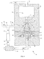
- FIG. 2 shows a schematic of a pulse generator 18 for use with a system 10 to mobilize lung secretions.
- the pulse generator 18 comprises a body 44 which receives compressed gas through inlet port 20 (also referred to as first port) shown in FIG. 2 .
- the compressed gas is air while in other embodiments the compressed gas is oxygen, in yet another embodiment any combination of gases may be supplied to the pulse generator 18.
- the body 44 comprises an air volume chamber (AVC) 22 (also referred to as first chamber 22) configured to receive air from inlet port 20.
- AVC 22 is configured to stabilize the pressure and make up for line losses.
- gases flow from the AVC 22 through plunger port 24 (also referred to as an intermediate port) and apply pressure on valve stem or plunger 26 with pressure P1.
- the plunger has a first end 102 and a second end 104.
- the valve stem 26 includes an O-ring 58. P1 acts on area A1 which is the top surface area of the valve stem.
- the valve stem 26 is configured to obscure fluidic connection between plunger port 24 and outlet port 40 (also referred to as second port).
- the pulse generator includes a first diaphragm 28 and a second diaphragm 30. As seen best in FIG. 7 a diaphragm assembly 106 is comprised of the second diaphragm 30 and a button 42.
- the first diaphragm has a plunger side 114 facing the plunger and an opposite side 116 facing the diaphragm assembly 106.
- the diaphragm assembly has an input side 110 and an output side 112.
- the valve stem 26 is configured to apply a component of the force it experiences due to pressure P1 on to first diaphragm 28.
- first diaphragm 28 is made of an elastomeric material while in other embodiment the first diaphragm 28 may be made of any material including but not limited to spring steel. In other embodiments the diaphragm may be of any shape including but not limited to a helical structure.
- a valve button 42 is configured to be separated from first diaphragm 28 in one embodiment by a clearance space C. In other embodiments the valve button 42 is in contact with first diaphragm 28. Motion of second diaphragm 30 is configured to move valve button 42.
- Gases from outlet port 40 are configured to feed into a flow restricting orifice 38 and also supply pressurized gas to a patient by way of discharge leg 80 of Wye fitting 78.
- the orifice 38 is a nozzle. Gases entering orifice 38 at pressure P2 exit the orifice 38 at pressure P6 which is less than P2.
- the gases exiting the orifice 38 enter a needle valve 36 and therefrom apply pressure P4 on second diaphragm 30 via second chamber 32.
- the needle valve 36 is configured to be situated outside the body 44 minimizing potential for thermal deformation of the body 44 and / or other components affecting the needle valve and minimizing frequency drifts.
- the orifice 38 is configured to be a safety feature to maintain the frequency of operation of the pulse generator 18 within a prescribed range in case of failure of the needle valve 36, in particular to limit the maximum frequency.
- the volume of chamber 32 can be changed by adjusting the control shaft of the needle valve. Doing so will change the pulse frequency of the pulse generator.
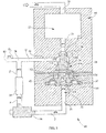
- FIGS. 3-6 show the operation of the pulse generator 18.
- compressed gases flows through inlet port 20 and into the AVC 22.
- the compressed gases apply a force F1 of magnitude shown by Equation 1 in a direction shown in FIG. 3 tending to deform first diaphragm 28.
- P1 is the pressure acting on plunger 26
- A1 is the area over which P1 acts when O-ring 58 is seated on O-ring seat 59.
- F ⁇ 1 P ⁇ 1 x A ⁇ 1
- valve stem 26 moves downwardly and deforms first diaphragm 28.
- the weight of the valve stem 26 and of the valve button 42 have been neglected in this embodiment, but in another embodiment the orientation of the pulse generator with respect to the gravitational force is taken into account.
- the valve stem 26 moves downwardly compressed gas from chamber 22 flows past the O-ring seat and through to outlet port 40.
- the fact that the valve stem has moved exposes an additional area (A2 in addition to A1) of valve stem 26 to pressure P1 exerted by the gas flowing past the O-ring seat.
- first diaphragm 28 and second diaphragm 30 are exposed to atmospheric pressure P atm while in other embodiments this space may be pressurized to a higher pressure and that pressure would be used for calculation of F2 in Equation 2 above instead of P atm .
- A3 is the area of first diaphragm 28 exposed to atmospheric pressure.
- A3 is the projected area in the direction of force F2.
- KA is the stiffness co-efficient (i.e. the spring constant) of first diaphragm 28 while DA is the deflection of the first diaphragm upon application of force by the valve stem 26.
- First diaphragm 28 is a linear spring in this embodiment while in another embodiment first diaphragm 28 is a non-linear spring.
- F1 exceeds F2 the valve stem 26 moves in the direction of F1 establishing a fluidic connection between plunger port 24 and outlet port 40.
- the pulse generator includes a conduit Q and a conduit P. Collectively the conduits Q and P define a fluid channel.
- the pulse generator also includes a patient delivery conduit Q1.
- Q1 connects with the fluid channel defined by Q and P at a juncture. The juncture is in the form of a Wye fitting 78 ( FIGS. 7 , 8A, 8B ).
- gases discharging from outlet port 40 flow through conduit Q. A portion of the gases flow through conduit Q1 to be delivered to a patient.
- Another portion of the gases flow through conduit P which includes orifice 38, and the needle valve 36 (conduits Q and P comprise a fluid channel extending from the outlet port to the input side of the diaphragm assembly). This increases the pressure P4 in second chamber 32.
- Equation 3 shows the summation of atmospheric pressure acting on area A4 in this embodiment and force required to deflect second diaphragm 30 where KB is the spring co-efficient (spring constant) of the second diaphragm and DB is its deflection.
- Second diaphragm 30 is configured to be a linear spring in this embodiment while in another embodiment second diaphragm 30 is a non-linear spring. In this embodiment clearance C is present between valve button 42 and first diaphragm 28.
- F ⁇ 3 P atm x A ⁇ 4 + KB x DB
- F ⁇ 4 P ⁇ 4 x A ⁇ 5
- valve button 42 contacts first diaphragm 28, further upward motion (or motion in direction of force F4) of valve button 42 urges upward displacement of first diaphragm 28. This, in turn, moves valve stem 26 in the direction of F4 (neglecting compression of first diaphragm 28 and weights of components).
- force F4 exceeds force F3' shown below in equation 6
- the valve button 42 pushes the valve stem 26 in the direction of F4 so as to reduce fluidic communication between plunger port 24 and outlet port 40.
- no clearance is present between the valve button 42 and the first diaphragm 28 so that the valve button 42 displaces first diaphragm 28 if F4 exceeds F3' calculated by Equations 5 and 6.
- F1' is the net force acting in the direction of F3 when the valve seat 26 is open wherein pressure P2 acts on a total projected area A1+A2.
- Force F3' acts in the direction of F3 in one embodiment.
- valve stem 26 begins to move in the direction of F1 again when F1 exceeds F2.
- This opening and closing of the fluidic communication pathway between plunger port 24 and outlet port 40 creates oscillating pressure at 80 which is supplied for high frequency oscillation therapy.
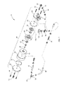
- FIG. 7 shows an exploded view of a pulse generator 18 for use with a system 10 to mobilize lung secretions.
- a pulse generator 18 for use with a system 10 to mobilize lung secretions.
- FIG. 7 addition or removal of any combination of parts including but not limited to tubing, seals and valves are contemplated in other embodiments. Further aggregation of separate components shown in FIG. 7 is contemplated in other embodiments, in one exemplary embodiment portions of the body 44 may be integrated into a single piece.
- a fitting 54 allows air into the body 44.
- the body 44 comprises the valve base 46, first valve section 48, second valve section 50 and third valve section 52.
- the fitting 54 is configured to connect to third valve section 52.
- Third valve section 52 is configured to be connected to second valve section 50 by at least one fastener 56.
- An O-ring seal 51 seals between the second valve section 50 and third section 52.
- O-Ring 58, valve stem 26 and diaphragm 28 are captured between the second valve section 50 and first valve section 48.
- Valve button 42 and second diaphragm 30 are captured between the valve base 46 and first diaphragm 28.
- a bracket 60 is configured to mount to the valve base 46.
- Fasteners 56 are configured to connect the bracket 60, valve base 46, and first valve section 48 with second valve section 50.
- Needle valve 36 is configured to fluidly connect with valve base 46 via tube 68, clamp 66 and swivel elbow 64.
- the swivel elbow is mounted to the valve base 46.
- the needle valve 36 is configured to mount on the bracket 60 by fasteners 56 connecting with a locking sleeve 74.
- the connection includes an elastomeric bushing 72.
- An orifice 38 fluidly connects with the needle valve 36 at one end and the other end of the orifice 38 connects with a Wye fitting 78 via tube 68.
- Wye fitting 78 is also fluidly connected to outlet port 40 as shown in FIG. 2 .
- Wye fitting includes a discharge leg 80.
- Wye fitting 78 supplies pulses of compressed gas through leg 80 for therapy.
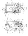
- FIG. 8 A & FIG. 8 B are perspective and front cross sectional views respectively of one embodiment of a pulse generator 18 for use with a system 10 to mobilize lung secretions showing some of the components shown in FIG. 7 .
- the AVC 22 is not incorporated into the body 44 and body 44 comprises a straight conduit up to plunger port 24.
- the pulse generator receives pressurized gas from a source thereof by way of inlet port 20.
- the pressurized gas moves the plunger 26 in a first direction toward the diaphragm assembly thereby increasing flow of the pressurized gas between the plunger port 24 and the outlet port 40.
- a first portion of the pressurized gas admitted through the outlet port acts on the input side 110 of the diaphragm assembly thereby urging the diaphragm assembly to move in a second direction opposite to the first direction.
- Pressure on the input side of the diaphragm assembly increases over time and eventually reverses the movement of the plunger so that the plunger moves in the second direction.
- the above described behavior comprises a cycle which can repeats N times where N is greater than one. During each cycle a second portion of the pressurized gas flows into the patient delivery channel in a pulsating fashion.
- An associated method of providing oscillatory pressurized gas comprises A) providing a pressurized gas from a source thereof, B) employing the pressurized gas to open a path to a fluid channel, C) directing a first portion of the gas to a delivery conduit, D) reducing the pressure of a second portion of the gas, and E) using the second portion to counteract the employing step.
- the step of using the second portion comprises accumulating the reduced pressure gas thereby elevating its pressure and enhancing its counteractiveness.
- Method steps B, C, D and E comprise a cycle. The method may proceed for N repetitions of the cycle where N is greater than one.
Landscapes
- Health & Medical Sciences (AREA)
- Emergency Medicine (AREA)
- Pulmonology (AREA)
- Engineering & Computer Science (AREA)
- Anesthesiology (AREA)
- Biomedical Technology (AREA)
- Heart & Thoracic Surgery (AREA)
- Hematology (AREA)
- Life Sciences & Earth Sciences (AREA)
- Animal Behavior & Ethology (AREA)
- General Health & Medical Sciences (AREA)
- Public Health (AREA)
- Veterinary Medicine (AREA)
- Infusion, Injection, And Reservoir Apparatuses (AREA)
- Massaging Devices (AREA)
Applications Claiming Priority (1)
| Application Number | Priority Date | Filing Date | Title |
|---|---|---|---|
| MYPI2012005095 | 2012-11-26 |
Publications (2)
| Publication Number | Publication Date |
|---|---|
| EP2735329A2 true EP2735329A2 (de) | 2014-05-28 |
| EP2735329A3 EP2735329A3 (de) | 2016-11-09 |
Family
ID=49679350
Family Applications (1)
| Application Number | Title | Priority Date | Filing Date |
|---|---|---|---|
| EP13193808.6A Withdrawn EP2735329A3 (de) | 2012-11-26 | 2013-11-21 | Impulserzeugungssysteme für Therapievorrichtungen |
Country Status (4)
| Country | Link |
|---|---|
| EP (1) | EP2735329A3 (de) |
| JP (1) | JP5806277B2 (de) |
| AU (1) | AU2013254952A1 (de) |
| CA (1) | CA2832687A1 (de) |
Cited By (1)
| Publication number | Priority date | Publication date | Assignee | Title |
|---|---|---|---|---|
| CN109010939A (zh) * | 2018-07-02 | 2018-12-18 | 袁永刚 | 一种用于肺癌手术的积液吸取装置 |
Family Cites Families (9)
| Publication number | Priority date | Publication date | Assignee | Title |
|---|---|---|---|---|
| US3083707A (en) * | 1956-02-13 | 1963-04-02 | Henry W Seeler | Device for treatment of pulmonary diseases |
| GB1138274A (en) * | 1966-03-04 | 1968-12-27 | Liston Fletcher Inc | Therapeutic respirator |
| JPS60104806A (ja) * | 1983-11-10 | 1985-06-10 | Itsusei Kogyo Kk | 気体圧力パルス発生装置 |
| FR2733917B1 (fr) * | 1995-05-12 | 1997-10-17 | Benarrouch Jacques | Variateur oscillatoire de pression pour reduire la viscosite des mucus thixotropes pour leur expectoration des poumons et des bronches |
| US7066175B2 (en) * | 2001-05-07 | 2006-06-27 | Emergent Respiratory Products, Inc. | Portable gas powered positive pressure breathing apparatus and method |
| FR2824479B1 (fr) * | 2001-05-14 | 2003-06-27 | Dominique Esteve | Dispositif pour appliquer un stimulus de pression pneumatique dans les fosses nasales et dans la trompe auditive au moment de la deglutition |
| US8225785B2 (en) * | 2006-10-03 | 2012-07-24 | Smiths Medical Asd, Inc. | Vibratory PEP therapy system with medicated aerosol nebulizer |
| US7779841B2 (en) * | 2006-11-13 | 2010-08-24 | Carefusion 2200, Inc. | Respiratory therapy device and method |
| NZ586099A (en) * | 2007-11-19 | 2012-05-25 | Carefusion 2200 Inc | Patient interface assembly comprising a jet pump including a venturi assembly defining an entrainment region, a throat region and an expansion region |
-
2013
- 2013-11-08 CA CA2832687A patent/CA2832687A1/en not_active Abandoned
- 2013-11-08 AU AU2013254952A patent/AU2013254952A1/en not_active Abandoned
- 2013-11-21 EP EP13193808.6A patent/EP2735329A3/de not_active Withdrawn
- 2013-11-25 JP JP2013243055A patent/JP5806277B2/ja not_active Expired - Fee Related
Non-Patent Citations (1)
| Title |
|---|
| None |
Cited By (1)
| Publication number | Priority date | Publication date | Assignee | Title |
|---|---|---|---|---|
| CN109010939A (zh) * | 2018-07-02 | 2018-12-18 | 袁永刚 | 一种用于肺癌手术的积液吸取装置 |
Also Published As
| Publication number | Publication date |
|---|---|
| JP5806277B2 (ja) | 2015-11-10 |
| CA2832687A1 (en) | 2014-05-26 |
| EP2735329A3 (de) | 2016-11-09 |
| JP2014111119A (ja) | 2014-06-19 |
| AU2013254952A1 (en) | 2014-06-12 |
Similar Documents
| Publication | Publication Date | Title |
|---|---|---|
| CA2223328C (en) | Pneumatically-operated gas demand apparatus | |
| EP3423137B1 (de) | Leichtes tragbares ventilatorsystem | |
| US5632270A (en) | Method and apparatus for control of lung ventilator exhalation circuit | |
| JP2019531776A5 (de) | ||
| US8307828B2 (en) | Pneumatic single-lumen medical gas conserver | |
| US10166360B2 (en) | System and method for controlling flow during exhalation in a respiratory support system | |
| US9352115B1 (en) | Respiratory ventilation system with gas sparing valve having optional CPAP mode and mask for use with same | |
| US6237594B1 (en) | Pneumatically-operated gas demand apparatus | |
| US10258759B2 (en) | Bi-level positive airway pressure device | |
| AU2008282597A1 (en) | Pressure reducing valve with flexible cuff | |
| US12161813B2 (en) | Device for ventilating a patient | |
| WO2008101302A1 (en) | Demand valve for breathing apparatus | |
| US20160339202A1 (en) | Ventilators and ventilator systems | |
| EP2735329A2 (de) | Impulserzeugungssysteme für Therapievorrichtungen | |
| EP2462974A1 (de) | Pneumatische Vibrationsdämpfungseinrichtung | |
| US20140163440A1 (en) | Pulse generator systems for therapy device | |
| US10583266B2 (en) | Bi-level positive airway pressure device | |
| US10576241B2 (en) | Breath powered positive airway pressure device | |
| JP2007503946A (ja) | バルブ | |
| US10583262B2 (en) | Device for detecting air flow | |
| US11433194B2 (en) | Device for detecting air flow | |
| US20220362506A1 (en) | Bi-level Positive Airway Pressure Device | |
| EP1897578B1 (de) | Absperrventil für die unterbrechungstechnik bei der analyse der atemmechanik | |
| US20230124131A1 (en) | Ventilation manifold and system | |
| CN118787829A (zh) | 具有阀中的震动补偿的呼吸组件以及呼吸方法 |
Legal Events
| Date | Code | Title | Description |
|---|---|---|---|
| PUAI | Public reference made under article 153(3) epc to a published international application that has entered the european phase |
Free format text: ORIGINAL CODE: 0009012 |
|
| 17P | Request for examination filed |
Effective date: 20131121 |
|
| AK | Designated contracting states |
Kind code of ref document: A2 Designated state(s): AL AT BE BG CH CY CZ DE DK EE ES FI FR GB GR HR HU IE IS IT LI LT LU LV MC MK MT NL NO PL PT RO RS SE SI SK SM TR |
|
| AX | Request for extension of the european patent |
Extension state: BA ME |
|
| PUAL | Search report despatched |
Free format text: ORIGINAL CODE: 0009013 |
|
| AK | Designated contracting states |
Kind code of ref document: A3 Designated state(s): AL AT BE BG CH CY CZ DE DK EE ES FI FR GB GR HR HU IE IS IT LI LT LU LV MC MK MT NL NO PL PT RO RS SE SI SK SM TR |
|
| AX | Request for extension of the european patent |
Extension state: BA ME |
|
| RIC1 | Information provided on ipc code assigned before grant |
Ipc: A61M 16/20 20060101ALI20161004BHEP Ipc: A61M 16/00 20060101AFI20161004BHEP |
|
| STAA | Information on the status of an ep patent application or granted ep patent |
Free format text: STATUS: THE APPLICATION IS DEEMED TO BE WITHDRAWN |
|
| 18D | Application deemed to be withdrawn |
Effective date: 20170510 |