EP2735511B1 - Système de transfert de puissance électrique pour système d'hélice - Google Patents
Système de transfert de puissance électrique pour système d'hélice Download PDFInfo
- Publication number
- EP2735511B1 EP2735511B1 EP13193880.5A EP13193880A EP2735511B1 EP 2735511 B1 EP2735511 B1 EP 2735511B1 EP 13193880 A EP13193880 A EP 13193880A EP 2735511 B1 EP2735511 B1 EP 2735511B1
- Authority
- EP
- European Patent Office
- Prior art keywords
- propeller
- slip ring
- assembly
- tube
- brush block
- Prior art date
- Legal status (The legal status is an assumption and is not a legal conclusion. Google has not performed a legal analysis and makes no representation as to the accuracy of the status listed.)
- Active
Links
Images


Classifications
-
- B—PERFORMING OPERATIONS; TRANSPORTING
- B64—AIRCRAFT; AVIATION; COSMONAUTICS
- B64D—EQUIPMENT FOR FITTING IN OR TO AIRCRAFT; FLIGHT SUITS; PARACHUTES; ARRANGEMENT OR MOUNTING OF POWER PLANTS OR PROPULSION TRANSMISSIONS IN AIRCRAFT
- B64D15/00—De-icing or preventing icing on exterior surfaces of aircraft
- B64D15/12—De-icing or preventing icing on exterior surfaces of aircraft by electric heating
-
- B—PERFORMING OPERATIONS; TRANSPORTING
- B64—AIRCRAFT; AVIATION; COSMONAUTICS
- B64C—AEROPLANES; HELICOPTERS
- B64C11/00—Propellers, e.g. of ducted type; Features common to propellers and rotors for rotorcraft
- B64C11/02—Hub construction
-
- F—MECHANICAL ENGINEERING; LIGHTING; HEATING; WEAPONS; BLASTING
- F03—MACHINES OR ENGINES FOR LIQUIDS; WIND, SPRING, OR WEIGHT MOTORS; PRODUCING MECHANICAL POWER OR A REACTIVE PROPULSIVE THRUST, NOT OTHERWISE PROVIDED FOR
- F03D—WIND MOTORS
- F03D80/00—Details, components or accessories not provided for in groups F03D1/00 - F03D17/00
- F03D80/70—Bearing or lubricating arrangements
-
- Y—GENERAL TAGGING OF NEW TECHNOLOGICAL DEVELOPMENTS; GENERAL TAGGING OF CROSS-SECTIONAL TECHNOLOGIES SPANNING OVER SEVERAL SECTIONS OF THE IPC; TECHNICAL SUBJECTS COVERED BY FORMER USPC CROSS-REFERENCE ART COLLECTIONS [XRACs] AND DIGESTS
- Y02—TECHNOLOGIES OR APPLICATIONS FOR MITIGATION OR ADAPTATION AGAINST CLIMATE CHANGE
- Y02E—REDUCTION OF GREENHOUSE GAS [GHG] EMISSIONS, RELATED TO ENERGY GENERATION, TRANSMISSION OR DISTRIBUTION
- Y02E10/00—Energy generation through renewable energy sources
- Y02E10/70—Wind energy
- Y02E10/72—Wind turbines with rotation axis in wind direction
Definitions
- the subject matter disclosed herein generally relates to propeller- equipped craft. More specifically, the subject disclosure relates to transfer of electrical power to propeller mounted components of the propeller-equipped craft.
- a typical rotor or propeller equipped craft is often equipped with components at the rotating rotor such as deicing components, which require electrical power for operation.
- the deicing components typically include heating elements embedded into the propeller blades. Wires carry electrical power to the heating elements when deicing is required. The heating elements melt accumulated ice and prevent subsequent formation of ice of the propeller blade surfaces.
- a plate rotating with the rotor is provided and one or more slip rings are mounted to it.
- the rotating slip rings interfaces with a stationary brush block mounted to a front cover of a reduction gear box for the engine driving the propeller.
- the brush block interfaces with a vertical face of the plate containing the slip rings forward of the gearbox.
- Leadwires from studs attached to the slip rings distribute electrical power to the various rotating components. Due to the necessary size of the slip rings, the presence of fluids and abrasive materials such as sand and dust in the brush block environment, a high level of wear occurs in the brush blocks carbon brushes and in the slip rings, resulting in excessive amounts of maintenance to repair and/or replace the brush block and slip ring components.
- FIG. 1 Shown in FIG. 1 is a schematic view of an embodiment of a propeller system 10 for an aircraft.
- the propeller system 10 includes a propeller assembly having a plurality of propeller blades 12 arranged around a hub 14. A pitch change actuator 11 is connected to an end of the hub 14.
- the propeller blades 12 include one or more heating elements 30 for deicing of the propeller blades 12.
- the propeller system 10 is operably connected to a reduction gearbox 16 via a propeller shaft 18, which is in turn connected to an engine 20.
- the reduction gearbox 16 translates a rotational speed of the engine 20 into a selected propeller speed, N p .
- the propeller shaft 18 is supported by shaft bearings 22. Further, one or more tubes, for example, oil transfer tube 24 extend along shaft axis 28 toward the propeller blades 12.
- the oil transfer tube 24 is supported by the pitch change actuator 11 and interfaces with a transfer bearing 32 to provide fluid to pitch change actuator 11 at the hub 14.
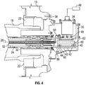
- a brush block 34 is located at an aft side of the gearbox 16, in other words the gearbox 16 is located between the propeller blades 12 and the brush block 34, relative to the shaft axis 28.
- the brush block 34 is at least partially supported by and enclosed in a brush block housing 36. In some embodiments, the brush block 34 is secured to an aft gearbox face 38.
- the oil transfer tube 24 includes a slip ring assembly 40, including a number of slip rings 42 molded into or assembled to a slip ring tube 44.
- the slip ring tube 44 is concentric with and is secured to the oil transfer tube 24.
- the slip ring assembly 40 includes three slip rings 42.
- the brush block 34 includes a number of brush block tips 46, which interface with the slip rings 42.
- the brush block 34 receives electrical power from a power source, for example, generator 48, and transfers the electrical power to the slip rings 42 via the brush block tips 46.
- the brush block tips 46 extend substantially radially relative to the shaft axis 28 toward the slip rings 42.
- the brush block tips 46 may be shimmed into a selected location relative to the slip rings 42.
- a number of lead wires 50 extend from the slip rings 42.
- the lead wires 50 are routed through a wire transfer tube 52 installed into the oil transfer tube 24.
- the wire transfer tube 52 rotates about the shaft axis 28 with the oil transfer tube 24 at N p .
- the wire transfer tube 52 is isolated from oil flow through the oil transfer tube 24 to protect the lead wires 50 from damage due to the oil flow.
- the lead wires 50 exit the wire transfer tube 52 at the hub 14 and are routed to the heating elements 30 to provide power thereto for deicing of the propeller blades 12.
- the slip rings 42 are assembled to, or molded into the slip ring tube 44, which is supported by slip ring bearings 60 located at a support shaft 62 extending from the brush block housing 36 into an interior of the slip ring tube 44.
- the slip ring assembly 40 is operably connected to the oil transfer tube 24 via a slip ring drive tab 64 extending from the slip ring tube 44 to a drive notch 66 at the oil transfer tube 24. The connection is such that rotation of the oil transfer tube 24 drives rotation of the slip ring tube 44, and thus the slip rings 42.
- Locating the slip ring assembly 40 and brush block 34 at an aft side of the gearbox 16 allows for a smaller slip ring tube 44 or utilization of a slip ring tube 44 secured to the oil transfer tube 24. This results in smaller diameter slip rings 42 and thus lower rotational speed of the slip rings 42 at the slip ring 42 / brush block tip 46 interface and less wear of the slip rings 42 and brush block tips 46. Further, location of the brush block 34 and slip rings 42 at an aft side of the gearbox 16 shields the brush block 34 and slip rings 42 from contaminants such as dust and sand, reducing erosion wear of the brush block 34 and slip rings 42.
- the electrical power may be provided to the rotating portions of the propeller system 10 for other components such as propeller control systems, propeller dynamic balance systems, instrumentation systems for propeller testing, or the like.
Landscapes
- Engineering & Computer Science (AREA)
- Aviation & Aerospace Engineering (AREA)
- Life Sciences & Earth Sciences (AREA)
- Sustainable Development (AREA)
- Sustainable Energy (AREA)
- Chemical & Material Sciences (AREA)
- Combustion & Propulsion (AREA)
- Mechanical Engineering (AREA)
- General Engineering & Computer Science (AREA)
- Motor Or Generator Current Collectors (AREA)
- Motor Power Transmission Devices (AREA)
Claims (13)
- Système d'hélice (10) pour un aéronef comprenant un ensemble hélice pouvant tourner autour d'un axe central (28), le système d'hélice (10) comprenant :une boîte d'engrenages de réduction (16) reliée de manière opérationnelle à l'ensemble hélice par l'intermédiaire d'un arbre d'hélice (18) ; etun système de transfert de puissance électrique positionné de sorte que la boîte d'engrenages (16) est située axialement entre le système de transfert de puissance électrique et l'ensemble hélice, ledit système de transfert de puissance électrique comprenant :un ensemble bague collectrice (40) relié de manière opérationnelle à un tube de transfert d'huile (24) s'étendant jusqu'à l'ensemble hélice ; etun bloc de balais (34) en interaction avec l'ensemble bague collectrice (40) pour transférer de la puissance électrique à une pluralité de fils conducteurs (50) s'étendant de l'ensemble bague collectrice (40) à l'ensemble hélice, le bloc de balais (34) étant positionné de sorte que les extrémités de bloc de balais (46) du bloc de balais (34) s'étendent vers l'ensemble bague collectrice (40) dans une direction sensiblement radiale par rapport à l'axe central (28).
- Système d'hélice (10) selon la revendication 1, dans lequel l'ensemble bague collectrice (42) comprend :un tube de bague collectrice (44) fixé au tube de transfert d'huile (24) ; etune pluralité de bagues collectrices (42) fixées au tube de bague collectrice (44).
- Système d'hélice (10) selon la revendication 2, dans lequel la pluralité de bagues collectrices (42) sont moulées dans le tube de bague collectrice (44).
- Système d'hélice (10) selon la revendication 1, dans lequel l'ensemble bague collectrice (42) comprend :un tube de bague collectrice (44) relié de manière opérationnelle au tube de transfert d'huile (24) par l'intermédiaire d'une patte d'entraînement de bague collectrice (64) ;un palier à bague collectrice (60) supportant le tube de bague collectrice (44) ; etune pluralité de bagues collectrices (42) fixées au tube de bague collectrice (44).
- Système d'hélice (10) selon une quelconque revendication précédente, comprenant en outre un tube d'acheminement de fil (52) disposé à l'intérieur du tube de transfert d'huile (24), les fils conducteurs (50) étant acheminés à travers le tube d'acheminement de fil (52).
- Système d'hélice (10) selon une quelconque revendication précédente, dans lequel le bloc de balais (34) est fixé à une face arrière (38) de la boîte d'engrenages (16).
- Système d'hélice (10) selon une quelconque revendication précédente, dans lequel l'ensemble hélice comprend une pluralité de pales d'hélice (12) s'étendant à partir d'un moyeu d'hélice (14) relié de manière opérationnelle à l'arbre d'hélice (18).
- Système d'hélice selon une quelconque revendication précédente, comprenant en outre un élément chauffant (30) relié de manière opérationnelle à une pale d'hélice (12) de l'ensemble hélice et en liaison électrique avec l'un de ladite pluralité de fils conducteurs (50).
- Système d'hélice (10) comprenant :un ensemble hélice et un système de dégivrage pour l'ensemble hélice ;le système d'hélice comprend en outre une boîte d'engrenages de réduction (16) reliée de manière opérationnelle à l'ensemble hélice par l'intermédiaire d'un arbre d'hélice (18) ; etle système de dégivrage comprend :un élément chauffant (30) relié de manière opérationnelle à une pale d'hélice (12) de l'ensemble hélice ;un bloc de balais (34) positionné de sorte que la boîte d'engrenages de réduction (16) est située entre le bloc de balais (34) et l'ensemble hélice ;un ensemble bague collectrice (40) fixé à un élément rotatif et en interaction avec le bloc de balais (34) pour transférer de la puissance électrique du bloc de balais (34) à l'élément chauffant (30) par l'intermédiaire d'une pluralité de fils conducteurs (50) s'étendant de l'ensemble bague collectrice (40) à l'élément chauffant (30), le bloc de balais (34) étant positionné de sorte que les extrémités de bloc de balais (46) du bloc de balais (34) s'étendent vers l'ensemble bague collectrice (40) dans une direction sensiblement radiale par rapport à un axe central (28) de l'ensemble hélice.
- Système d'hélice selon la revendication 9, dans lequel l'ensemble bague collectrice (40) comprend :un tube de bague collectrice (44) fixé à un tube de transfert d'huile (24) disposé au niveau de l'axe central (28) de l'ensemble hélice ; etune pluralité de bagues collectrices (42) fixées au tube de bague collectrice (44).
- Système d'hélice selon la revendication 10, dans lequel la pluralité de bagues collectrices (42) sont moulées dans le tube de bague collectrice (44).
- Système d'hélice selon la revendication 9, dans lequel l'ensemble bague collectrice (40) comprend :un tube de bague collectrice (44) couplé de manière opérationnelle à un tube de transfert d'huile (24) disposé au niveau d'un axe central (28) de l'ensemble hélice par l'intermédiaire d'une patte d'entraînement de bague collectrice (64) ;un palier à bague collectrice (60) supportant le tube de bague collectrice (44) ; etune pluralité de bagues collectrices (42) fixées au tube de bague collectrice (44).
- Système d'hélice selon l'une quelconque des revendications 9 à 12, dans lequel le bloc de balais (34) est fixé à une face arrière (38) de la boîte d'engrenages (16).
Applications Claiming Priority (1)
| Application Number | Priority Date | Filing Date | Title |
|---|---|---|---|
| US13/685,243 US9227731B2 (en) | 2012-11-26 | 2012-11-26 | Electrical power transfer system for propeller system |
Publications (3)
| Publication Number | Publication Date |
|---|---|
| EP2735511A2 EP2735511A2 (fr) | 2014-05-28 |
| EP2735511A3 EP2735511A3 (fr) | 2016-11-23 |
| EP2735511B1 true EP2735511B1 (fr) | 2019-05-29 |
Family
ID=49724950
Family Applications (1)
| Application Number | Title | Priority Date | Filing Date |
|---|---|---|---|
| EP13193880.5A Active EP2735511B1 (fr) | 2012-11-26 | 2013-11-21 | Système de transfert de puissance électrique pour système d'hélice |
Country Status (2)
| Country | Link |
|---|---|
| US (1) | US9227731B2 (fr) |
| EP (1) | EP2735511B1 (fr) |
Families Citing this family (2)
| Publication number | Priority date | Publication date | Assignee | Title |
|---|---|---|---|---|
| US10288163B2 (en) | 2015-10-23 | 2019-05-14 | General Electric Company | Method and system for a planetary power gearbox static to rotating oil transfer supply |
| CN112896498B (zh) * | 2021-03-12 | 2022-11-22 | 核工业二八0研究所 | 一种无人机伽马能谱测量系统 |
Family Cites Families (7)
| Publication number | Priority date | Publication date | Assignee | Title |
|---|---|---|---|---|
| US2425353A (en) * | 1942-09-05 | 1947-08-12 | Jr Lyman Spitzer | Flexible, variable-diameter propeller |
| US2402770A (en) * | 1943-08-21 | 1946-06-25 | Curtiss Wright Corp | Anti-icing means for aircraft propellers |
| US2429061A (en) * | 1943-10-28 | 1947-10-14 | Goodrich Co B F | Counter-rotating propeller assembly |
| CA1069870A (fr) | 1977-03-04 | 1980-01-15 | B.F. Goodrich Company (The) | Degrivreur d'helice |
| US5634800A (en) * | 1994-04-29 | 1997-06-03 | The B. F. Goodrich Company | Sliding contact for a propeller ice protection system |
| US8365866B2 (en) * | 2008-07-10 | 2013-02-05 | General Electric Company | Internal lubrication for a gearbox, a power-generating wind turbine system, and a power-generating system |
| EP2545275B1 (fr) * | 2010-03-10 | 2016-08-17 | SSB Wind Systems GmbH & Co. KG | Système de pas redondant |
-
2012
- 2012-11-26 US US13/685,243 patent/US9227731B2/en active Active
-
2013
- 2013-11-21 EP EP13193880.5A patent/EP2735511B1/fr active Active
Non-Patent Citations (1)
| Title |
|---|
| None * |
Also Published As
| Publication number | Publication date |
|---|---|
| EP2735511A3 (fr) | 2016-11-23 |
| EP2735511A2 (fr) | 2014-05-28 |
| US20140147275A1 (en) | 2014-05-29 |
| US9227731B2 (en) | 2016-01-05 |
Similar Documents
| Publication | Publication Date | Title |
|---|---|---|
| EP2730506B1 (fr) | Système de transfert de puissance électrique pour système d'hélice | |
| EP3055516B1 (fr) | Protecteur d'engrenage à balayage automatique | |
| US8162611B2 (en) | Controllable pitch propeller with electrical power generation | |
| US20170030335A1 (en) | Drive system of a wind turbine | |
| US6769874B2 (en) | Permanent magnet alternator for a gas turbine engine | |
| CN106460538B (zh) | 具有可变间距的叶片的涡轮发动机压气机 | |
| CN112088129B (zh) | 设置有用于向叶片提供电能的旋转变压器的飞行器推进组件 | |
| KR102274446B1 (ko) | 호버링 가능한 항공기 | |
| JP2016538451A (ja) | 雷電流伝達システム及び雷電流伝達システムを用いる風力タービン | |
| CN107776876B (zh) | 装有可分离轴承箱的飞机轮 | |
| EP2282839B1 (fr) | Séparateur centrifuge | |
| US20070160460A1 (en) | Ram air turbine with compound geartrain gearbox | |
| JP2016527135A (ja) | プロペラブレード支持装置 | |
| EP2735511B1 (fr) | Système de transfert de puissance électrique pour système d'hélice | |
| CN113382920A (zh) | 摆线船用推进单元和配备有其的船舶 | |
| US8932002B2 (en) | Air turbine starter | |
| EP3214314B1 (fr) | Ventilateur axial sans palier | |
| US9725166B2 (en) | Counter-rotating rotor system with static mast | |
| US9238972B2 (en) | Ram air turbine pump leakage control | |
| US10494089B2 (en) | Drive shaft system hanger bearing | |
| CN104890497A (zh) | 混合动力模块 | |
| EP3636968B1 (fr) | Palier de déconnexion et joint d'entrée améliorés pour un générateur de démarreur à fréquence variable | |
| CN102857013B (zh) | 电机轴承故障辅助保护结构 | |
| EP4063649B1 (fr) | Rétromontage d'éoliennes | |
| US10322797B2 (en) | Rotating sealing systems |
Legal Events
| Date | Code | Title | Description |
|---|---|---|---|
| PUAI | Public reference made under article 153(3) epc to a published international application that has entered the european phase |
Free format text: ORIGINAL CODE: 0009012 |
|
| 17P | Request for examination filed |
Effective date: 20131121 |
|
| AK | Designated contracting states |
Kind code of ref document: A2 Designated state(s): AL AT BE BG CH CY CZ DE DK EE ES FI FR GB GR HR HU IE IS IT LI LT LU LV MC MK MT NL NO PL PT RO RS SE SI SK SM TR |
|
| AX | Request for extension of the european patent |
Extension state: BA ME |
|
| PUAL | Search report despatched |
Free format text: ORIGINAL CODE: 0009013 |
|
| AK | Designated contracting states |
Kind code of ref document: A3 Designated state(s): AL AT BE BG CH CY CZ DE DK EE ES FI FR GB GR HR HU IE IS IT LI LT LU LV MC MK MT NL NO PL PT RO RS SE SI SK SM TR |
|
| AX | Request for extension of the european patent |
Extension state: BA ME |
|
| RIC1 | Information provided on ipc code assigned before grant |
Ipc: B64C 11/44 20060101ALI20161019BHEP Ipc: B64D 15/12 20060101AFI20161019BHEP |
|
| STAA | Information on the status of an ep patent application or granted ep patent |
Free format text: STATUS: REQUEST FOR EXAMINATION WAS MADE |
|
| R17P | Request for examination filed (corrected) |
Effective date: 20170523 |
|
| RBV | Designated contracting states (corrected) |
Designated state(s): AL AT BE BG CH CY CZ DE DK EE ES FI FR GB GR HR HU IE IS IT LI LT LU LV MC MK MT NL NO PL PT RO RS SE SI SK SM TR |
|
| GRAP | Despatch of communication of intention to grant a patent |
Free format text: ORIGINAL CODE: EPIDOSNIGR1 |
|
| STAA | Information on the status of an ep patent application or granted ep patent |
Free format text: STATUS: GRANT OF PATENT IS INTENDED |
|
| INTG | Intention to grant announced |
Effective date: 20181203 |
|
| RIN1 | Information on inventor provided before grant (corrected) |
Inventor name: PLICKYS, MARK R. Inventor name: CARVALHO, PAUL A. |
|
| GRAS | Grant fee paid |
Free format text: ORIGINAL CODE: EPIDOSNIGR3 |
|
| GRAA | (expected) grant |
Free format text: ORIGINAL CODE: 0009210 |
|
| STAA | Information on the status of an ep patent application or granted ep patent |
Free format text: STATUS: THE PATENT HAS BEEN GRANTED |
|
| AK | Designated contracting states |
Kind code of ref document: B1 Designated state(s): AL AT BE BG CH CY CZ DE DK EE ES FI FR GB GR HR HU IE IS IT LI LT LU LV MC MK MT NL NO PL PT RO RS SE SI SK SM TR |
|
| REG | Reference to a national code |
Ref country code: GB Ref legal event code: FG4D |
|
| REG | Reference to a national code |
Ref country code: CH Ref legal event code: EP |
|
| REG | Reference to a national code |
Ref country code: AT Ref legal event code: REF Ref document number: 1138112 Country of ref document: AT Kind code of ref document: T Effective date: 20190615 |
|
| REG | Reference to a national code |
Ref country code: DE Ref legal event code: R096 Ref document number: 602013055986 Country of ref document: DE |
|
| REG | Reference to a national code |
Ref country code: IE Ref legal event code: FG4D |
|
| REG | Reference to a national code |
Ref country code: NL Ref legal event code: MP Effective date: 20190529 |
|
| REG | Reference to a national code |
Ref country code: LT Ref legal event code: MG4D |
|
| PG25 | Lapsed in a contracting state [announced via postgrant information from national office to epo] |
Ref country code: FI Free format text: LAPSE BECAUSE OF FAILURE TO SUBMIT A TRANSLATION OF THE DESCRIPTION OR TO PAY THE FEE WITHIN THE PRESCRIBED TIME-LIMIT Effective date: 20190529 Ref country code: NO Free format text: LAPSE BECAUSE OF FAILURE TO SUBMIT A TRANSLATION OF THE DESCRIPTION OR TO PAY THE FEE WITHIN THE PRESCRIBED TIME-LIMIT Effective date: 20190829 Ref country code: LT Free format text: LAPSE BECAUSE OF FAILURE TO SUBMIT A TRANSLATION OF THE DESCRIPTION OR TO PAY THE FEE WITHIN THE PRESCRIBED TIME-LIMIT Effective date: 20190529 Ref country code: HR Free format text: LAPSE BECAUSE OF FAILURE TO SUBMIT A TRANSLATION OF THE DESCRIPTION OR TO PAY THE FEE WITHIN THE PRESCRIBED TIME-LIMIT Effective date: 20190529 Ref country code: PT Free format text: LAPSE BECAUSE OF FAILURE TO SUBMIT A TRANSLATION OF THE DESCRIPTION OR TO PAY THE FEE WITHIN THE PRESCRIBED TIME-LIMIT Effective date: 20190930 Ref country code: ES Free format text: LAPSE BECAUSE OF FAILURE TO SUBMIT A TRANSLATION OF THE DESCRIPTION OR TO PAY THE FEE WITHIN THE PRESCRIBED TIME-LIMIT Effective date: 20190529 Ref country code: AL Free format text: LAPSE BECAUSE OF FAILURE TO SUBMIT A TRANSLATION OF THE DESCRIPTION OR TO PAY THE FEE WITHIN THE PRESCRIBED TIME-LIMIT Effective date: 20190529 Ref country code: SE Free format text: LAPSE BECAUSE OF FAILURE TO SUBMIT A TRANSLATION OF THE DESCRIPTION OR TO PAY THE FEE WITHIN THE PRESCRIBED TIME-LIMIT Effective date: 20190529 |
|
| PG25 | Lapsed in a contracting state [announced via postgrant information from national office to epo] |
Ref country code: GR Free format text: LAPSE BECAUSE OF FAILURE TO SUBMIT A TRANSLATION OF THE DESCRIPTION OR TO PAY THE FEE WITHIN THE PRESCRIBED TIME-LIMIT Effective date: 20190830 Ref country code: LV Free format text: LAPSE BECAUSE OF FAILURE TO SUBMIT A TRANSLATION OF THE DESCRIPTION OR TO PAY THE FEE WITHIN THE PRESCRIBED TIME-LIMIT Effective date: 20190529 Ref country code: RS Free format text: LAPSE BECAUSE OF FAILURE TO SUBMIT A TRANSLATION OF THE DESCRIPTION OR TO PAY THE FEE WITHIN THE PRESCRIBED TIME-LIMIT Effective date: 20190529 Ref country code: BG Free format text: LAPSE BECAUSE OF FAILURE TO SUBMIT A TRANSLATION OF THE DESCRIPTION OR TO PAY THE FEE WITHIN THE PRESCRIBED TIME-LIMIT Effective date: 20190829 |
|
| REG | Reference to a national code |
Ref country code: AT Ref legal event code: MK05 Ref document number: 1138112 Country of ref document: AT Kind code of ref document: T Effective date: 20190529 |
|
| PG25 | Lapsed in a contracting state [announced via postgrant information from national office to epo] |
Ref country code: SK Free format text: LAPSE BECAUSE OF FAILURE TO SUBMIT A TRANSLATION OF THE DESCRIPTION OR TO PAY THE FEE WITHIN THE PRESCRIBED TIME-LIMIT Effective date: 20190529 Ref country code: CZ Free format text: LAPSE BECAUSE OF FAILURE TO SUBMIT A TRANSLATION OF THE DESCRIPTION OR TO PAY THE FEE WITHIN THE PRESCRIBED TIME-LIMIT Effective date: 20190529 Ref country code: RO Free format text: LAPSE BECAUSE OF FAILURE TO SUBMIT A TRANSLATION OF THE DESCRIPTION OR TO PAY THE FEE WITHIN THE PRESCRIBED TIME-LIMIT Effective date: 20190529 Ref country code: AT Free format text: LAPSE BECAUSE OF FAILURE TO SUBMIT A TRANSLATION OF THE DESCRIPTION OR TO PAY THE FEE WITHIN THE PRESCRIBED TIME-LIMIT Effective date: 20190529 Ref country code: DK Free format text: LAPSE BECAUSE OF FAILURE TO SUBMIT A TRANSLATION OF THE DESCRIPTION OR TO PAY THE FEE WITHIN THE PRESCRIBED TIME-LIMIT Effective date: 20190529 Ref country code: NL Free format text: LAPSE BECAUSE OF FAILURE TO SUBMIT A TRANSLATION OF THE DESCRIPTION OR TO PAY THE FEE WITHIN THE PRESCRIBED TIME-LIMIT Effective date: 20190529 Ref country code: EE Free format text: LAPSE BECAUSE OF FAILURE TO SUBMIT A TRANSLATION OF THE DESCRIPTION OR TO PAY THE FEE WITHIN THE PRESCRIBED TIME-LIMIT Effective date: 20190529 |
|
| PG25 | Lapsed in a contracting state [announced via postgrant information from national office to epo] |
Ref country code: IT Free format text: LAPSE BECAUSE OF FAILURE TO SUBMIT A TRANSLATION OF THE DESCRIPTION OR TO PAY THE FEE WITHIN THE PRESCRIBED TIME-LIMIT Effective date: 20190529 Ref country code: SM Free format text: LAPSE BECAUSE OF FAILURE TO SUBMIT A TRANSLATION OF THE DESCRIPTION OR TO PAY THE FEE WITHIN THE PRESCRIBED TIME-LIMIT Effective date: 20190529 |
|
| REG | Reference to a national code |
Ref country code: DE Ref legal event code: R097 Ref document number: 602013055986 Country of ref document: DE |
|
| PG25 | Lapsed in a contracting state [announced via postgrant information from national office to epo] |
Ref country code: TR Free format text: LAPSE BECAUSE OF FAILURE TO SUBMIT A TRANSLATION OF THE DESCRIPTION OR TO PAY THE FEE WITHIN THE PRESCRIBED TIME-LIMIT Effective date: 20190529 |
|
| PLBE | No opposition filed within time limit |
Free format text: ORIGINAL CODE: 0009261 |
|
| STAA | Information on the status of an ep patent application or granted ep patent |
Free format text: STATUS: NO OPPOSITION FILED WITHIN TIME LIMIT |
|
| PG25 | Lapsed in a contracting state [announced via postgrant information from national office to epo] |
Ref country code: PL Free format text: LAPSE BECAUSE OF FAILURE TO SUBMIT A TRANSLATION OF THE DESCRIPTION OR TO PAY THE FEE WITHIN THE PRESCRIBED TIME-LIMIT Effective date: 20190529 |
|
| 26N | No opposition filed |
Effective date: 20200303 |
|
| PG25 | Lapsed in a contracting state [announced via postgrant information from national office to epo] |
Ref country code: SI Free format text: LAPSE BECAUSE OF FAILURE TO SUBMIT A TRANSLATION OF THE DESCRIPTION OR TO PAY THE FEE WITHIN THE PRESCRIBED TIME-LIMIT Effective date: 20190529 |
|
| REG | Reference to a national code |
Ref country code: DE Ref legal event code: R119 Ref document number: 602013055986 Country of ref document: DE |
|
| REG | Reference to a national code |
Ref country code: CH Ref legal event code: PL |
|
| PG25 | Lapsed in a contracting state [announced via postgrant information from national office to epo] |
Ref country code: CH Free format text: LAPSE BECAUSE OF NON-PAYMENT OF DUE FEES Effective date: 20191130 Ref country code: LU Free format text: LAPSE BECAUSE OF NON-PAYMENT OF DUE FEES Effective date: 20191121 Ref country code: MC Free format text: LAPSE BECAUSE OF FAILURE TO SUBMIT A TRANSLATION OF THE DESCRIPTION OR TO PAY THE FEE WITHIN THE PRESCRIBED TIME-LIMIT Effective date: 20190529 Ref country code: LI Free format text: LAPSE BECAUSE OF NON-PAYMENT OF DUE FEES Effective date: 20191130 |
|
| REG | Reference to a national code |
Ref country code: BE Ref legal event code: MM Effective date: 20191130 |
|
| PG25 | Lapsed in a contracting state [announced via postgrant information from national office to epo] |
Ref country code: IE Free format text: LAPSE BECAUSE OF NON-PAYMENT OF DUE FEES Effective date: 20191121 Ref country code: DE Free format text: LAPSE BECAUSE OF NON-PAYMENT OF DUE FEES Effective date: 20200603 |
|
| PG25 | Lapsed in a contracting state [announced via postgrant information from national office to epo] |
Ref country code: BE Free format text: LAPSE BECAUSE OF NON-PAYMENT OF DUE FEES Effective date: 20191130 |
|
| PG25 | Lapsed in a contracting state [announced via postgrant information from national office to epo] |
Ref country code: CY Free format text: LAPSE BECAUSE OF FAILURE TO SUBMIT A TRANSLATION OF THE DESCRIPTION OR TO PAY THE FEE WITHIN THE PRESCRIBED TIME-LIMIT Effective date: 20190529 |
|
| PG25 | Lapsed in a contracting state [announced via postgrant information from national office to epo] |
Ref country code: IS Free format text: LAPSE BECAUSE OF FAILURE TO SUBMIT A TRANSLATION OF THE DESCRIPTION OR TO PAY THE FEE WITHIN THE PRESCRIBED TIME-LIMIT Effective date: 20190929 |
|
| PG25 | Lapsed in a contracting state [announced via postgrant information from national office to epo] |
Ref country code: HU Free format text: LAPSE BECAUSE OF FAILURE TO SUBMIT A TRANSLATION OF THE DESCRIPTION OR TO PAY THE FEE WITHIN THE PRESCRIBED TIME-LIMIT; INVALID AB INITIO Effective date: 20131121 Ref country code: MT Free format text: LAPSE BECAUSE OF FAILURE TO SUBMIT A TRANSLATION OF THE DESCRIPTION OR TO PAY THE FEE WITHIN THE PRESCRIBED TIME-LIMIT Effective date: 20190529 |
|
| PG25 | Lapsed in a contracting state [announced via postgrant information from national office to epo] |
Ref country code: MK Free format text: LAPSE BECAUSE OF FAILURE TO SUBMIT A TRANSLATION OF THE DESCRIPTION OR TO PAY THE FEE WITHIN THE PRESCRIBED TIME-LIMIT Effective date: 20190529 |
|
| P01 | Opt-out of the competence of the unified patent court (upc) registered |
Effective date: 20230522 |
|
| PGFP | Annual fee paid to national office [announced via postgrant information from national office to epo] |
Ref country code: GB Payment date: 20251023 Year of fee payment: 13 |
|
| PGFP | Annual fee paid to national office [announced via postgrant information from national office to epo] |
Ref country code: FR Payment date: 20251022 Year of fee payment: 13 |