EP2735706B1 - Gleichrichter mit Laufradschaufeln eines Kompressors eines axialen Turbotriebwerks, und Herstellungsverfahren - Google Patents
Gleichrichter mit Laufradschaufeln eines Kompressors eines axialen Turbotriebwerks, und Herstellungsverfahren Download PDFInfo
- Publication number
- EP2735706B1 EP2735706B1 EP12193700.7A EP12193700A EP2735706B1 EP 2735706 B1 EP2735706 B1 EP 2735706B1 EP 12193700 A EP12193700 A EP 12193700A EP 2735706 B1 EP2735706 B1 EP 2735706B1
- Authority
- EP
- European Patent Office
- Prior art keywords
- stator
- platforms
- openings
- groove
- internal
- Prior art date
- Legal status (The legal status is an assumption and is not a legal conclusion. Google has not performed a legal analysis and makes no representation as to the accuracy of the status listed.)
- Active
Links
Images


Classifications
-
- F—MECHANICAL ENGINEERING; LIGHTING; HEATING; WEAPONS; BLASTING
- F01—MACHINES OR ENGINES IN GENERAL; ENGINE PLANTS IN GENERAL; STEAM ENGINES
- F01D—NON-POSITIVE DISPLACEMENT MACHINES OR ENGINES, e.g. STEAM TURBINES
- F01D9/00—Stators
- F01D9/02—Nozzles; Nozzle boxes; Stator blades; Guide conduits, e.g. individual nozzles
-
- F—MECHANICAL ENGINEERING; LIGHTING; HEATING; WEAPONS; BLASTING
- F01—MACHINES OR ENGINES IN GENERAL; ENGINE PLANTS IN GENERAL; STEAM ENGINES
- F01D—NON-POSITIVE DISPLACEMENT MACHINES OR ENGINES, e.g. STEAM TURBINES
- F01D9/00—Stators
- F01D9/02—Nozzles; Nozzle boxes; Stator blades; Guide conduits, e.g. individual nozzles
- F01D9/04—Nozzles; Nozzle boxes; Stator blades; Guide conduits, e.g. individual nozzles forming ring or sector
- F01D9/042—Nozzles; Nozzle boxes; Stator blades; Guide conduits, e.g. individual nozzles forming ring or sector fixing blades to stators
- F01D9/044—Nozzles; Nozzle boxes; Stator blades; Guide conduits, e.g. individual nozzles forming ring or sector fixing blades to stators permanently, e.g. by welding, brazing, casting or the like
-
- Y—GENERAL TAGGING OF NEW TECHNOLOGICAL DEVELOPMENTS; GENERAL TAGGING OF CROSS-SECTIONAL TECHNOLOGIES SPANNING OVER SEVERAL SECTIONS OF THE IPC; TECHNICAL SUBJECTS COVERED BY FORMER USPC CROSS-REFERENCE ART COLLECTIONS [XRACs] AND DIGESTS
- Y02—TECHNOLOGIES OR APPLICATIONS FOR MITIGATION OR ADAPTATION AGAINST CLIMATE CHANGE
- Y02T—CLIMATE CHANGE MITIGATION TECHNOLOGIES RELATED TO TRANSPORTATION
- Y02T50/00—Aeronautics or air transport
- Y02T50/60—Efficient propulsion technologies, e.g. for aircraft
-
- Y—GENERAL TAGGING OF NEW TECHNOLOGICAL DEVELOPMENTS; GENERAL TAGGING OF CROSS-SECTIONAL TECHNOLOGIES SPANNING OVER SEVERAL SECTIONS OF THE IPC; TECHNICAL SUBJECTS COVERED BY FORMER USPC CROSS-REFERENCE ART COLLECTIONS [XRACs] AND DIGESTS
- Y10—TECHNICAL SUBJECTS COVERED BY FORMER USPC
- Y10T—TECHNICAL SUBJECTS COVERED BY FORMER US CLASSIFICATION
- Y10T29/00—Metal working
- Y10T29/49—Method of mechanical manufacture
- Y10T29/49316—Impeller making
- Y10T29/4932—Turbomachine making
- Y10T29/49323—Assembling fluid flow directing devices, e.g., stators, diaphragms, nozzles
Definitions
- the invention relates to an axial turbomachine rectifier.
- the invention also relates to an axial turbomachine comprising a compressor and a turbine provided with rectifiers.
- the invention also relates to a method of manufacturing an axial turbomachine rectifier.
- an axial turbomachine compressor commonly has a plurality of stages.
- a stage consists essentially of a row of rotor blades followed by a row of stator vanes. The cumulative dimensions of these stages dictate the length of the compressor.
- the document FR 2 404 102 A1 has an axially turbomachine fixed blade crown.
- the ring has an outer shell having openings disposed in an annular row.
- the blades comprise external platforms which are welded at the openings of the outer shell.
- the outer shell comprises an annular cavity filled with abradable material, said cavity being located near openings and platforms.
- the cross section of the ferrule thus has a variable thickness portion near the soda area between the ferrule and the platforms. The thickness of variable material near the weld bead generates inhomogeneity that can cause problems in the realization of the weld.
- the document FR 2 958 323 A discloses a turbomachine low pressure compressor comprising several stages of a vane straightener.
- a rectifier stage has an outer shell in which aligned orifices are formed.
- the blades present platforms whose contours follow the inner edges of the orifices of the outer shell.
- a weld made at their junction makes it possible to fix the vanes via their platforms to the outer shell.
- the extent of the platforms makes it possible not to expose the bodies of the blades during the welding operation.
- the weld must have a homogeneous medium. This may result in the weld being made at a distance from elbows, and preferably through parts having constant thicknesses. To overcome these constraints, the bent area must be away from the blades, which leads to extend the platforms of the blades, and therefore the compressor.
- the low pressure compressor occupies a large space.
- the lengthening has an impact on the size and sizing of the casing of the turbomachine.
- the weight of the latter is found increased.
- this weight increases the on-board weight, as well as the resources to allow it to lift.
- the primary energy requirements and the lift surface must be adapted.
- the document EP 2 202 388 A1 discloses an overlapping turbomachine stator assembly. Two cylindrical portions forming stator flanges overlap at the stator vanes. This assembly rests on a fixation by blind bolts. Although reducing the axial size, this solution increases the radial size. In addition this solution is not suitable for a welding operation since visual inspection of both sides of the weld is not allowed. This configuration does not lend itself to electron bombardment welding due to the presence of the blade under the weld.
- the object of the invention is to solve at least one problem raised in the prior art. More particularly, the invention aims to lighten the turbomachine. More particularly, the invention aims to make the turbomachine more compact. The invention also aims to improve the efficiency of the turbomachine and more particularly of its compressor.
- the invention relates to an axial turbomachine rectifier comprising an outer shell with an annular row of openings and at least one inner annular groove for receiving an annular layer of abradable material, a row of stator blades with platforms. disposed in the apertures and secured by one or more weld seams between the platforms and apertures, characterized in that the row of apertures and the inner groove overlap partially so that a portion of the one or more strands welding is positioned axially at the height of the internal groove and the platforms extend over a portion of the bottom of the internal groove.
- the platforms of the blades form a projection delimiting the internal groove.
- the openings pass through the shell and the groove.
- the platforms have a generally parallelogram shape, preferably rectangle, with an upstream side and a downstream side, the portion of the weld seam (s) positioned axially at the height of the internal groove. extending along one of the upstream and downstream sides of the parallelogram.
- the openings extend in a principal direction mainly oriented along the axis of the straightener, said principal direction forming preferably an angle less than 45 °, more preferably less than 30 °, more preferably still less than 15 ° with said axis.
- the outer shell comprises a preferably unitary circular wall, with a first section comprising the internal groove and a second section comprising the row of openings and vanes, said wall forming a shoulder between said sections.
- the platforms have surfaces complementary to the openings.
- the outer shell and / or the stator blade platforms are generally of constant thickness.
- the platforms of the blades are essentially embedded in the openings of the outer shell.
- the section of the internal groove extends in a main direction substantially corresponding to the axis of the rectifier, and has a substantially constant depth, greater than 1.00 mm, preferably greater than 2.00 mm; still more preferably greater than 3.00 mm.
- the inner annular groove has two shoulders, at least one of the two shoulders is inclined relative to the perpendicular to the bottom of the inner annular groove.
- the rectifier has vanes fixed to the outer shell in a means other than a weld.
- the rectifier is a compressor rectifier, preferably a low-pressure compressor.
- low pressure compressor means a compressor arranged after the turbofan. Its input pressure is similar to the atmospheric pressure encountered at the altitudes of evolution of an aircraft.
- the internal annular groove has a length greater than 5.00 mm; preferably greater than 10.00 mm; preferably greater than 20.00 mm. The length is measured along the axis of the rectifier.
- the materials of at least one platform and the shell are alloy shades substantially similar or compatible to be welded.
- the ferrule comprises two internal annular grooves, one being disposed upstream and the other downstream of the openings, a first part of the weld or seams being located in the upstream groove. and a second portion of the weld seam (s) being located in the downstream groove.
- the platforms have a thickness greater than the outer shell at the openings.
- the weld has a welding interruption on the edges of the annular groove of the outer shell.
- the platform has a portion extending along the outer face of the outer shell and which is welded to said face at an axial height of the internal groove.
- the invention also relates to a turbomachine comprising at least one compressor with at least one rectifier, and at least one turbine with at least one rectifier, characterized in that the or at least one of the rectifiers of the compressor and / or the turbine is according to the invention.
- the invention also relates to a method of manufacturing a rectifier according to the invention, comprising the following steps: (a) provision of the outer shell and blades; (b) establishment and welding the platforms in the openings of the outer shell; (c) implementing the layer of abradable material in the internal groove.
- the method comprises the following step between steps (b) and (c): machining of the inner surface of the shell to form the internal groove.
- the invention makes it possible to shorten a turbomachine by acting on the compressor.
- Each stage of rectifier combined with a band of abradable material makes it possible to gain a few millimeters. One centimeter can be recovered on the whole of a low pressure compressor.
- the invention also provides aerodynamic gain since the vein side welds are covered by the abradable material. Indeed, some of the roughness of the welds in the vein are now covered by the abradable. This result is achieved by lengthening the weld, as well as the realization of a platform and an outer shell with a step.
- the invention facilitates the design of a turbomachine and does not require to spare unexploited spaces between the rows of blades and moving blades. If necessary, the latter can be brought closer together in order to better manage the flows, and thus optimize the efficiency of the turbomachine.
- inner and outer refer to a positioning relative to the axis of rotation of an axial turbomachine. The same goes for internal and external terms.
- the lengths are measured along the axis of rotation of the turbomachine, the heights radially and the widths perpendicular to the heights.
- the figure 1 schematizes an axial turbomachine. It is in this case a double-flow turbojet engine.
- the turbojet engine 2 comprises a first compression level, called a low-pressure compressor 8, a second compression level, called a high-pressure compressor 10, a combustion chamber 12 and one or more levels of turbines 14.
- a first compression level called a low-pressure compressor 8
- a second compression level called a high-pressure compressor 10
- a combustion chamber 12 and one or more levels of turbines 14.
- Reducing means can increase the speed of rotation transmitted to the compressors.
- the different stages of turbines can be each connected to the compressor stages via concentric shafts. The latter comprise several rows of rotor blades associated with rows of stator vanes.
- Rotation of the rotor thus makes it possible to generate an air flow and to compress it gradually until it reaches the combustion chamber 12.
- the "turbofan" inlet valve 6 is coupled to the rotor 4 and generates a stream of air which divides into a primary stream 16 passing through the above mentioned levels of the turbomachine, and a secondary stream 18 passing through an annular duct (partially shown) along the machine to then join the primary flow at the turbine outlet.
- the figure 2 is a sectional view of a low-pressure compressor of an axial turbomachine such as that of the figure 1 .
- the rotor 4 comprises several rows of rotor blades 22.
- the housing comprises a plurality of rectifiers 24 associated with Rotor vane rows 22.
- Each rectifier comprises a row of stator vanes 26.
- Each pair of rows of associated rotor and stator vanes form a compression stage of the compressor 8.
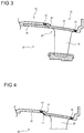
- the figure 3 illustrates a turbomachine rectifier portion 24.
- the rectifier 24 forms a ring having as an axis of symmetry the axis of rotation of the turbomachine. It comprises an outer shell 28 on which is fixed a stator vane 26.
- the outer shell 28 has an inner surface for channeling the primary flow. Its inner surface is a surface of revolution. It is substantially cylindrical and shows a variation in diameter, for example a decrease in diameter in the flow direction.
- the ferrule has a body of revolution following a profile of revolution.
- the revolution profile has a first section 30 and a second section 32 connected by a bent zone 34. The first section 30 and the second section 32 may be nested at the bent zone 34.
- the first section 30 may be an upstream part. It has an internal annular groove in which is present an annular layer of abradable material 36. This material is able to erode by friction when a rotor blade end 22 comes into contact with it.
- the layer of abradable material 36 may form an annular band of substantially constant thickness, in order to lighten it and simplify its implementation.
- the inner surface of the layer of abradable material 36 is flush with the inner surface of the platform of the stator vane 26. This configuration makes it possible to optimize the flow by not creating a surface discontinuity capable of disturbing the flow.
- the length of the layer of abradable material 36 is imposed by the length of the end of the rotor blade 22 arranged opposite. Upstream and downstream margins can be added to take into account the service deformations of the turbomachine. These lengths are measured along the axis of rotation of the turbomachine. The length of the layer of abradable material 36 can be considered as a fixed data of the geometry of the turbomachine.
- the second section 32 may be a downstream part. It has an outer annular groove forming an annular recess. This recess makes it possible to lighten the outer shell.
- the first section 32 has an opening through the outer shell 28.
- the stator blade has a platform 38 of surface complementary to the opening so as to be able to hide the latter.
- the platform 38 is fixed at its junction with the opening, preferably at its edges, preferably over its entire contour.
- the fixing is carried out by welding, preferably with the aid of a weld bead, preferably continuous.
- the weld bead is made all around the opening so as to create a seal.
- the weld forms a weld bead with an upstream portion 40 and a downstream portion 42, as well as side portions (not shown). This welding can be performed by electron bombardment.
- the second section 32 comprises a row of openings receiving a row of stator vanes at their platforms.
- the outer contours of the platforms 38 run along the inner edges of the openings.
- the openings have similar shapes, just like the platforms 38
- the upstream portion 40 of the weld is disposed under the layer of abradable material 36. At this location, the profile of the body of the outer shell 28 is substantially straight.
- the upstream portion of the weld 40 is implanted so as to overcome the geometric constraints. This weld location makes it no longer available between the bent zone 34 and the body of the stator vane. Thus, the constraints that require extending the platform between the bent zone 34 and the body of the dawn no longer exist.
- the length of the upstream portion of the weld 40 is less than the length of the layer of abradable material 36, the presence of the upstream portion of the weld 40 no longer affects the length of the outer ferrule 28.
- the part of the platform between the body of the stator vane and the bent zone 34 can be shortened.
- This economy of axial length is reflected on the outer shell 28.
- all the welded stator blades of the same floor must have their upstream portion 40 solder disposed in the same groove.
- a substantial gain can be achieved. This gain may be greater than 2.00 mm, preferably greater than 3.00 mm.
- the invention at the scale of a compressor comprising several compression stages, for example three compression stages, can make it possible to gain more than 10.00 mm.
- the casing of the turbomachine can also be shortened. These size reductions make it possible to lighten the turbomachine, and to make it more robust.
- the teaching of the invention can also be applied to a turbomachine turbine stator.
- a weld of a straightener blade platform can be moved axially out of a stressed area.
- the abradable material may be a material with a honeycomb structure.
- the figure 4 presents an intermediate step of producing the rectifier 24 according to a first manufacturing method.
- the rectifier 24 is made from an outer shell with openings in which are housed the platforms.
- the ferrule 28 and the platforms 38 generally have their finite ribs.
- a weld seam is made at the junction between the platforms and the openings of the outer shell.
- the weld bead is essentially thin, its thickness is close to that of the outer shell 28. It is economical to achieve because of its small section.
- An excess thickness 44 may be added at the platform in the bent zone 34. After welding, the excess thickness 44 is machined, for example by turning.
- the figure 5 represents a first intermediate step of a second manufacturing method of the rectifier 24 which is represented in FIG. figure 3 .
- This figure 5 resumes the numbering of the preceding figures for the corresponding elements, however the numbering is incremented by 100. Specific numbers are used for the elements specific to this embodiment.
- the rectifier is made from raw platforms 138 and a raw blade 126 with a rough outer shell 128 having radial excess thicknesses. They may have equal thicknesses at their junction.
- the raw platforms 138 of the raw stator vanes 126 are placed in the openings of the outer ferrule 128, and are then welded to their junctions.
- the figure 5 illustrates a raw upstream portion 140 and a raw downstream portion 142 of the weld seam. The assembly thus obtained forms a crude rectifier 124.
- the figure 6 represents a second intermediate step of the second rectifier manufacturing method.
- the second intermediate step comprises machining operations of the raw rectifier 124 represented in FIG. figure 5 . Machining operations may include rough machining and / or finishing machining.
- Internal machining 102 is performed on the inner surface of the crude rectifier 124. It creates an annular groove in which the layer of abradable material can be deposited. Several annular grooves can be made to accommodate several annular layers of abradable material arranged axially.
- the internal machining 102 extends axially on the outer ferrule 128 and on a portion of the raw platforms 138. It also performs a removal of material in the upstream portion 102 of the weld bead.
- One or more external machining operations 104 can be performed on the outer surface of the raw rectifier 124. These machining operations make it possible to lighten the rectifier by removing material. Such machining can be performed at the level of the raw platforms 138 of the stator vanes, as well as in the downstream portion 142 of the weld bead.
- the internal and / or external machining operations are advantageously performed by turning to improve their circularity and cylindricity.
- the second manufacturing method has the advantage of welding on a flat surface. This weld will be more homogeneous and therefore more resistant. Moreover, a weld can modify the crystalline structure of materials and make it more fragile. This embrittlement combined with a bent shape can reduce the life of a part thus achieved. Thermal and vibratory stresses can precipitate mechanical failure. Having a weld under the band of abradable material; away from the bent part, the ferrule retains a longer life.
Landscapes
- Engineering & Computer Science (AREA)
- Mechanical Engineering (AREA)
- General Engineering & Computer Science (AREA)
- Structures Of Non-Positive Displacement Pumps (AREA)
Claims (14)
- Gleichrichter (24) einer axialen Turbomaschine, bestehend aus:- einem äußeren Ring (28) mit einer ringförmigen Reihe von Öffnungen und mindestens einer ringförmigen inneren Auskehlung, die für die Aufnahme einer ringförmigen Schicht eines verschleißbaren Materials (36) bestimmt ist,- einer Reihe von Leitschaufeln (26) mit Plattformen (38), die in den Öffnungen angeordnet sind und anhand einer Schweißnaht oder mehrerer Schweißnähte zwischen den Plattformen (38) und den Öffnungen befestigt sind,dadurch gekennzeichnet, dass sich die Reihe von Öffnungen und die innere Auskehlung teilweise in der Weise überlagern, dass ein Teil (40, 42) der Schweißnaht oder der Schweißnähte axial in Höhe der inneren Auskehlung positioniert ist und sich die Plattformen (38) über einen Teil des Bodens der inneren Auskehlung erstrecken.
- Gleichrichter (24) nach Anspruch 1, dadurch gekennzeichnet, dass die Plattformen (38) und die Leitschaufeln (26) einen Vorsprung bilden, der die innere Auskehlung begrenzt.
- Gleichrichter (24) nach einem der Ansprüche 1 bis 2, dadurch gekennzeichnet, dass die Öffnungen den Ring (28) und die innere Auskehlung durchqueren.
- Gleichrichter (24) nach einem der Ansprüche 1 bis 3, dadurch gekennzeichnet, dass die Plattformen (38) die allgemeine Form eines Parallelogramms, vorzugsweise eines Rechtecks haben, mit einer Oberseite und einer Unterseite, wobei sich der Teil (40, 42) der Schweißnaht oder der Schweißnähte, der axial in Höhe des inneren Auskehlung positioniert ist, entlang einer der Ober- und Unterseiten des Parallelogramms erstreckt.
- Gleichrichter (24) nach einem der Ansprüche 1 bis 4, dadurch gekennzeichnet, dass sich die Öffnungen in einer Hauptrichtung erstrecken, die mehrheitlich entlang der Achse des Gleichrichters (24) ausgerichtet ist, wobei die genannte Hauptrichtung vorzugsweise einen Winkel von unter 45°, bevorzugter unter 30° und noch bevorzugter unter 15° mit der genannten Achse bildet.
- Gleichrichter (24) nach einem der Ansprüche 1 bis 5, dadurch gekennzeichnet, dass der äußere Ring (28) eine ringförmige, vorzugsweise aus einem Stück bestehende Wandung beinhaltet, mit einem ersten Abschnitt (30), der die interne Auskehlung beinhaltet und einem zweiten Abschnitt (32), der die Reihe von Öffnungen und Leitschaufeln (26) beinhaltet, wobei die genannte Wandung eine Schulter zwischen den genannten Abschnitten bildet.
- Gleichrichter (24) nach einem der Ansprüche 1 bis 6, dadurch gekennzeichnet, dass die Plattformen (38) Oberflächen aufweisen, die sich komplementär zu den Öffnungen verhalten.
- Gleichrichter (24) nach einem der Ansprüche 1 bis 7, dadurch gekennzeichnet, dass der äußere Ring (28) und/oder die Plattformen (38) der Leitschaufeln (26) im Allgemeinen eine konstante Dicke aufweisen.
- Gleichrichter (24) nach einem der Ansprüche 1 bis 8, dadurch gekennzeichnet, dass die Plattformen (38) der Leitschaufeln (26) im Wesentlichen in die Öffnungen des äußeren Rings (28) eingelassen sind.
- Gleichrichter (24) nach einem der Ansprüche 1 bis 9, dadurch gekennzeichnet, dass sich der Querschnitt der internen Auskehlung in einer Hauptrichtung erstreckt, die im Wesentlichen der Achse des Gleichrichters (24) entspricht und eine annähernd konstante Tiefe von mehr als 1,00 mm, vorzugsweise mehr als 2,00 und noch bevorzugter von mehr als 3,00 mm aufweist.
- Gleichrichter (24) nach einem der Ansprüche 1 bis 10, dadurch gekennzeichnet, dass die ringförmige innere Auskehlung zwei Schultern aufweist, wobei mindestens eine der beiden Schultern im Verhältnis zur Lotrechten am Boden der inneren ringförmigen Auskehlung geneigt ist.
- Turbomaschine mit mindestens einem Kompressor (8, 10) mit mindestens einem Gleichrichter und mindestens einer Turbine (14) mit mindestens einem Gleichrichter, dadurch gekennzeichnet, dass der oder mindestens einer der Gleichrichter (24) des Kompressors (8, 10) und/oder der Turbine einem der Ansprüche 1 bis 11 entspricht.
- Verfahren für die Herstellung eines Gleichrichters nach einem der Ansprüche 1 bis 11, das die folgenden Phasen einschließt:(a) Bereitstellung des äußeren Rings (28) und der Leitschaufeln (26);(b) Einsetzen und Schweißen der Plattformen (38) in die Öffnungen des äußeren Rings (28);(c) Aufbringen der Schicht aus einem verschleißbaren Material (36) in der inneren Auskehlung.
- Verfahren für die Herstellung eines Gleichrichters (24) nach Anspruch 13, dadurch gekennzeichnet, dass es die folgende Phase zwischen den Phasen (b) und (c) einschließt: Bearbeitung der inneren Oberfläche des Rings (28), um die innere Auskehlung zu bilden.
Priority Applications (5)
| Application Number | Priority Date | Filing Date | Title |
|---|---|---|---|
| EP12193700.7A EP2735706B8 (de) | 2012-11-21 | 2012-11-21 | Gleichrichter mit Laufradschaufeln eines Kompressors eines axialen Turbotriebwerks, und Herstellungsverfahren |
| CA2832772A CA2832772C (en) | 2012-11-21 | 2013-11-13 | Stator blades of an axial turbocompressor and manufacturing process |
| CN201310757144.7A CN103836002A (zh) | 2012-11-21 | 2013-11-21 | 轴流式涡轮压缩机的定子叶片及其制造工艺 |
| RU2013151836/06A RU2568353C2 (ru) | 2012-11-21 | 2013-11-21 | Статор осевой турбомашины, способ его производства и турбомашина, содержащая указанный статор |
| US14/085,928 US20140294574A1 (en) | 2012-11-21 | 2013-11-21 | Stator Blades of an Axial Turbocompressor and Manufacturing Process |
Applications Claiming Priority (1)
| Application Number | Priority Date | Filing Date | Title |
|---|---|---|---|
| EP12193700.7A EP2735706B8 (de) | 2012-11-21 | 2012-11-21 | Gleichrichter mit Laufradschaufeln eines Kompressors eines axialen Turbotriebwerks, und Herstellungsverfahren |
Publications (3)
| Publication Number | Publication Date |
|---|---|
| EP2735706A1 EP2735706A1 (de) | 2014-05-28 |
| EP2735706B1 true EP2735706B1 (de) | 2016-06-22 |
| EP2735706B8 EP2735706B8 (de) | 2016-12-07 |
Family
ID=47355820
Family Applications (1)
| Application Number | Title | Priority Date | Filing Date |
|---|---|---|---|
| EP12193700.7A Active EP2735706B8 (de) | 2012-11-21 | 2012-11-21 | Gleichrichter mit Laufradschaufeln eines Kompressors eines axialen Turbotriebwerks, und Herstellungsverfahren |
Country Status (5)
| Country | Link |
|---|---|
| US (1) | US20140294574A1 (de) |
| EP (1) | EP2735706B8 (de) |
| CN (1) | CN103836002A (de) |
| CA (1) | CA2832772C (de) |
| RU (1) | RU2568353C2 (de) |
Families Citing this family (10)
| Publication number | Priority date | Publication date | Assignee | Title |
|---|---|---|---|---|
| FR3022578B1 (fr) * | 2014-06-23 | 2016-06-03 | Snecma | Procede de realisation et de reparation d’un distributeur de turbine d’une turbomachine |
| BE1024523B1 (fr) * | 2016-08-30 | 2018-03-29 | Safran Aero Boosters S.A. | Stator a aubes ajustables pour compresseur de turbomachine axiale |
| FR3061740B1 (fr) * | 2017-01-11 | 2019-08-09 | Safran Aircraft Engines | Redresseur a tenue vibratoire renforcee |
| CN107762568A (zh) * | 2017-09-30 | 2018-03-06 | 中国航发沈阳发动机研究所 | 焊接形成的风扇机匣 |
| CN107747563B (zh) * | 2017-09-30 | 2020-04-10 | 中国航发沈阳发动机研究所 | 带阻尼的风扇机匣 |
| CN110044668B (zh) * | 2018-01-17 | 2022-05-24 | 中国航发商用航空发动机有限责任公司 | 表征薄壁叶片铸件叶身性能的试样制造方法 |
| CN109882255B (zh) * | 2019-03-01 | 2021-10-19 | 西安航天动力研究所 | 带叶片型线槽的涡轮静子顶部封严限位结构 |
| FR3094906B1 (fr) * | 2019-04-12 | 2022-06-10 | Safran Aircraft Engines | Procede de fabrication d’un element aubage de stator pour une turbomachine et outillage pour sa mise en oeuvre |
| CN110076524B (zh) * | 2019-04-30 | 2020-07-31 | 沈阳透平机械股份有限公司 | 一种轴流型压缩机静叶流道板的加工方法 |
| FR3097800B1 (fr) | 2019-06-27 | 2022-09-30 | Safran Aircraft Engines | Procede de fabrication d’un carter pour une turbomachine et outillages pour sa mise en oeuvre |
Family Cites Families (15)
| Publication number | Priority date | Publication date | Assignee | Title |
|---|---|---|---|---|
| FR2404102A1 (fr) | 1977-09-27 | 1979-04-20 | Snecma | Couronne d'aubage fixe pour turbomachine axiale et son procede de realisation |
| US4655682A (en) * | 1985-09-30 | 1987-04-07 | United Technologies Corporation | Compressor stator assembly having a composite inner diameter shroud |
| CN1039088A (zh) * | 1988-07-02 | 1990-01-24 | 尼古拉·米哈洛维奇·诺维考夫 | 涡轮分子真空泵 |
| US4874290A (en) * | 1988-08-26 | 1989-10-17 | Solar Turbines Incorporated | Turbine blade top clearance control system |
| US6935836B2 (en) * | 2002-06-05 | 2005-08-30 | Allison Advanced Development Company | Compressor casing with passive tip clearance control and endwall ovalization control |
| US7189064B2 (en) * | 2004-05-14 | 2007-03-13 | General Electric Company | Friction stir welded hollow airfoils and method therefor |
| DE102004036066A1 (de) * | 2004-07-24 | 2006-02-16 | Mtu Aero Engines Gmbh | Verfahren zum Reparieren bzw. Fertigen eines Bauteils |
| US20080063508A1 (en) * | 2006-09-08 | 2008-03-13 | Barry Barnett | Fan case abradable |
| EP2075416B1 (de) * | 2007-12-27 | 2011-05-18 | Techspace Aero | Verfahren zur Herstellung eines Teils einer Strömungsmaschine und so erhaltene Vorrichtung |
| JP5115622B2 (ja) * | 2008-03-31 | 2013-01-09 | 株式会社島津製作所 | ターボ分子ポンプ |
| CN101392748B (zh) * | 2008-10-31 | 2011-04-27 | 东北大学 | 卧式干式真空泵 |
| EP2202388A1 (de) | 2008-12-23 | 2010-06-30 | Techspace Aero S.A. | Flanschaufbau |
| EP2204541B1 (de) * | 2008-12-24 | 2012-03-07 | Techspace Aero S.A. | Rotorstufe einer einteilig beschaufelten Verdichtertrommel einer axialen Strömungsmaschine und entsprechendes Herstellungsverfahren. |
| FR2958323B1 (fr) | 2010-03-30 | 2012-05-04 | Snecma | Etage redresseur de compresseur pour une turbomachine. |
| US20130052004A1 (en) * | 2011-08-25 | 2013-02-28 | Nicholas D. Stilin | Structural composite fan exit guide vane for a turbomachine |
-
2012
- 2012-11-21 EP EP12193700.7A patent/EP2735706B8/de active Active
-
2013
- 2013-11-13 CA CA2832772A patent/CA2832772C/en not_active Expired - Fee Related
- 2013-11-21 RU RU2013151836/06A patent/RU2568353C2/ru not_active IP Right Cessation
- 2013-11-21 US US14/085,928 patent/US20140294574A1/en not_active Abandoned
- 2013-11-21 CN CN201310757144.7A patent/CN103836002A/zh active Pending
Also Published As
| Publication number | Publication date |
|---|---|
| RU2013151836A (ru) | 2015-05-27 |
| EP2735706B8 (de) | 2016-12-07 |
| US20140294574A1 (en) | 2014-10-02 |
| RU2568353C2 (ru) | 2015-11-20 |
| CN103836002A (zh) | 2014-06-04 |
| CA2832772A1 (en) | 2014-05-21 |
| EP2735706A1 (de) | 2014-05-28 |
| CA2832772C (en) | 2015-12-29 |
Similar Documents
| Publication | Publication Date | Title |
|---|---|---|
| EP2735706B1 (de) | Gleichrichter mit Laufradschaufeln eines Kompressors eines axialen Turbotriebwerks, und Herstellungsverfahren | |
| EP3797212B1 (de) | Dichtung zwischen segmenten eines leitschaufelkranzes einer stromungsmaschine | |
| EP2801702B1 (de) | Stator-innenring eines turbotriebwerks mit abriebmaterial | |
| EP2896796B1 (de) | Stator einer axialen Strömungsmaschine und zugehörige Strömungsmaschine | |
| EP3463737A1 (de) | Turbomaschinenabgasgehäuse und verfahren zur herstellung davon | |
| EP3521569B1 (de) | Strukturgehäuse für axiale turbomaschine | |
| EP2795068B1 (de) | Leitschaufelanordnung eines turbomaschinenverdichters | |
| EP3409902B1 (de) | Abdichtungssystem für kompressor einer strömungsmaschine | |
| EP2937516B1 (de) | Rundgebogenes Monoblock-Gehäuse für Kompressor einer axialen Turbomaschine und entsprechendes Fertigungsverfahren | |
| CA2760667C (fr) | Virole pour stator de turbomoteur d'aeronef a fentes de dechargement mecanique d'aubes | |
| WO2020239732A1 (fr) | Joint d'étanchéité dynamique pour turbomachine comprenant une pièce abradable multicouche | |
| EP3382242B1 (de) | Bürstendichtung für rotor einer turbomaschine | |
| FR3118891A1 (fr) | Fabrication d’un injecteur de turbine par fusion laser sur lit de poudre | |
| FR3094034A1 (fr) | Chemise tubulaire de ventilation pour un distributeur de turbomachine | |
| EP3382155B1 (de) | Dichtungssystem für eine strömungsmaschine, und zugehörige strömungsmaschine | |
| BE1030042B1 (fr) | Roue mobile a anneau intermediaire | |
| EP4143421A1 (de) | Gehäuse mit zwischenflussglättung mit monoblockstrukturarm | |
| BE1030472B1 (fr) | Separateur de flux dans une turbomachine triple-flux | |
| BE1030039B1 (fr) | Separateur de flux dans une turbomachine | |
| EP4569209B1 (de) | Verstellbare leitschaufel für flugzeugturbomaschine und flugzeugturbomaschine | |
| FR2993804A1 (fr) | Soudage par friction des redresseurs et bras creux sur le carter intermediaire d'une turbomachine | |
| BE1027190B1 (fr) | Rotor hybride avec inserts | |
| BE1026460B1 (fr) | Carter structural pour turbomachine axiale | |
| FR3113298A1 (fr) | Porte-abradable d’un distributeur basse pression comprenant une unique tôle |
Legal Events
| Date | Code | Title | Description |
|---|---|---|---|
| PUAI | Public reference made under article 153(3) epc to a published international application that has entered the european phase |
Free format text: ORIGINAL CODE: 0009012 |
|
| 17P | Request for examination filed |
Effective date: 20121121 |
|
| AK | Designated contracting states |
Kind code of ref document: A1 Designated state(s): AL AT BE BG CH CY CZ DE DK EE ES FI FR GB GR HR HU IE IS IT LI LT LU LV MC MK MT NL NO PL PT RO RS SE SI SK SM TR |
|
| AX | Request for extension of the european patent |
Extension state: BA ME |
|
| R17P | Request for examination filed (corrected) |
Effective date: 20141128 |
|
| RBV | Designated contracting states (corrected) |
Designated state(s): AL AT BE BG CH CY CZ DE DK EE ES FI FR GB GR HR HU IE IS IT LI LT LU LV MC MK MT NL NO PL PT RO RS SE SI SK SM TR |
|
| GRAP | Despatch of communication of intention to grant a patent |
Free format text: ORIGINAL CODE: EPIDOSNIGR1 |
|
| INTG | Intention to grant announced |
Effective date: 20160107 |
|
| GRAS | Grant fee paid |
Free format text: ORIGINAL CODE: EPIDOSNIGR3 |
|
| GRAA | (expected) grant |
Free format text: ORIGINAL CODE: 0009210 |
|
| AK | Designated contracting states |
Kind code of ref document: B1 Designated state(s): AL AT BE BG CH CY CZ DE DK EE ES FI FR GB GR HR HU IE IS IT LI LT LU LV MC MK MT NL NO PL PT RO RS SE SI SK SM TR |
|
| REG | Reference to a national code |
Ref country code: GB Ref legal event code: FG4D Free format text: NOT ENGLISH |
|
| REG | Reference to a national code |
Ref country code: CH Ref legal event code: EP |
|
| REG | Reference to a national code |
Ref country code: IE Ref legal event code: FG4D Free format text: LANGUAGE OF EP DOCUMENT: FRENCH |
|
| REG | Reference to a national code |
Ref country code: AT Ref legal event code: REF Ref document number: 807794 Country of ref document: AT Kind code of ref document: T Effective date: 20160715 |
|
| REG | Reference to a national code |
Ref country code: DE Ref legal event code: R096 Ref document number: 602012019705 Country of ref document: DE |
|
| RAP2 | Party data changed (patent owner data changed or rights of a patent transferred) |
Owner name: SAFRAN AERO BOOSTER S.A. |
|
| GRAT | Correction requested after decision to grant or after decision to maintain patent in amended form |
Free format text: ORIGINAL CODE: EPIDOSNCDEC |
|
| REG | Reference to a national code |
Ref country code: LT Ref legal event code: MG4D |
|
| REG | Reference to a national code |
Ref country code: NL Ref legal event code: MP Effective date: 20160622 |
|
| PG25 | Lapsed in a contracting state [announced via postgrant information from national office to epo] |
Ref country code: NO Free format text: LAPSE BECAUSE OF FAILURE TO SUBMIT A TRANSLATION OF THE DESCRIPTION OR TO PAY THE FEE WITHIN THE PRESCRIBED TIME-LIMIT Effective date: 20160922 Ref country code: FI Free format text: LAPSE BECAUSE OF FAILURE TO SUBMIT A TRANSLATION OF THE DESCRIPTION OR TO PAY THE FEE WITHIN THE PRESCRIBED TIME-LIMIT Effective date: 20160622 Ref country code: LT Free format text: LAPSE BECAUSE OF FAILURE TO SUBMIT A TRANSLATION OF THE DESCRIPTION OR TO PAY THE FEE WITHIN THE PRESCRIBED TIME-LIMIT Effective date: 20160622 |
|
| REG | Reference to a national code |
Ref country code: AT Ref legal event code: MK05 Ref document number: 807794 Country of ref document: AT Kind code of ref document: T Effective date: 20160622 |
|
| REG | Reference to a national code |
Ref country code: FR Ref legal event code: PLFP Year of fee payment: 5 |
|
| PG25 | Lapsed in a contracting state [announced via postgrant information from national office to epo] |
Ref country code: HR Free format text: LAPSE BECAUSE OF FAILURE TO SUBMIT A TRANSLATION OF THE DESCRIPTION OR TO PAY THE FEE WITHIN THE PRESCRIBED TIME-LIMIT Effective date: 20160622 Ref country code: GR Free format text: LAPSE BECAUSE OF FAILURE TO SUBMIT A TRANSLATION OF THE DESCRIPTION OR TO PAY THE FEE WITHIN THE PRESCRIBED TIME-LIMIT Effective date: 20160923 Ref country code: NL Free format text: LAPSE BECAUSE OF FAILURE TO SUBMIT A TRANSLATION OF THE DESCRIPTION OR TO PAY THE FEE WITHIN THE PRESCRIBED TIME-LIMIT Effective date: 20160622 Ref country code: RS Free format text: LAPSE BECAUSE OF FAILURE TO SUBMIT A TRANSLATION OF THE DESCRIPTION OR TO PAY THE FEE WITHIN THE PRESCRIBED TIME-LIMIT Effective date: 20160622 Ref country code: SE Free format text: LAPSE BECAUSE OF FAILURE TO SUBMIT A TRANSLATION OF THE DESCRIPTION OR TO PAY THE FEE WITHIN THE PRESCRIBED TIME-LIMIT Effective date: 20160622 Ref country code: LV Free format text: LAPSE BECAUSE OF FAILURE TO SUBMIT A TRANSLATION OF THE DESCRIPTION OR TO PAY THE FEE WITHIN THE PRESCRIBED TIME-LIMIT Effective date: 20160622 |
|
| PG25 | Lapsed in a contracting state [announced via postgrant information from national office to epo] |
Ref country code: EE Free format text: LAPSE BECAUSE OF FAILURE TO SUBMIT A TRANSLATION OF THE DESCRIPTION OR TO PAY THE FEE WITHIN THE PRESCRIBED TIME-LIMIT Effective date: 20160622 Ref country code: IT Free format text: LAPSE BECAUSE OF FAILURE TO SUBMIT A TRANSLATION OF THE DESCRIPTION OR TO PAY THE FEE WITHIN THE PRESCRIBED TIME-LIMIT Effective date: 20160622 Ref country code: SK Free format text: LAPSE BECAUSE OF FAILURE TO SUBMIT A TRANSLATION OF THE DESCRIPTION OR TO PAY THE FEE WITHIN THE PRESCRIBED TIME-LIMIT Effective date: 20160622 Ref country code: RO Free format text: LAPSE BECAUSE OF FAILURE TO SUBMIT A TRANSLATION OF THE DESCRIPTION OR TO PAY THE FEE WITHIN THE PRESCRIBED TIME-LIMIT Effective date: 20160622 Ref country code: CZ Free format text: LAPSE BECAUSE OF FAILURE TO SUBMIT A TRANSLATION OF THE DESCRIPTION OR TO PAY THE FEE WITHIN THE PRESCRIBED TIME-LIMIT Effective date: 20160622 Ref country code: IS Free format text: LAPSE BECAUSE OF FAILURE TO SUBMIT A TRANSLATION OF THE DESCRIPTION OR TO PAY THE FEE WITHIN THE PRESCRIBED TIME-LIMIT Effective date: 20161022 |
|
| PG25 | Lapsed in a contracting state [announced via postgrant information from national office to epo] |
Ref country code: ES Free format text: LAPSE BECAUSE OF FAILURE TO SUBMIT A TRANSLATION OF THE DESCRIPTION OR TO PAY THE FEE WITHIN THE PRESCRIBED TIME-LIMIT Effective date: 20160622 Ref country code: SM Free format text: LAPSE BECAUSE OF FAILURE TO SUBMIT A TRANSLATION OF THE DESCRIPTION OR TO PAY THE FEE WITHIN THE PRESCRIBED TIME-LIMIT Effective date: 20160622 Ref country code: PL Free format text: LAPSE BECAUSE OF FAILURE TO SUBMIT A TRANSLATION OF THE DESCRIPTION OR TO PAY THE FEE WITHIN THE PRESCRIBED TIME-LIMIT Effective date: 20160622 Ref country code: PT Free format text: LAPSE BECAUSE OF FAILURE TO SUBMIT A TRANSLATION OF THE DESCRIPTION OR TO PAY THE FEE WITHIN THE PRESCRIBED TIME-LIMIT Effective date: 20161024 Ref country code: AT Free format text: LAPSE BECAUSE OF FAILURE TO SUBMIT A TRANSLATION OF THE DESCRIPTION OR TO PAY THE FEE WITHIN THE PRESCRIBED TIME-LIMIT Effective date: 20160622 |
|
| REG | Reference to a national code |
Ref country code: DE Ref legal event code: R097 Ref document number: 602012019705 Country of ref document: DE |
|
| PLBE | No opposition filed within time limit |
Free format text: ORIGINAL CODE: 0009261 |
|
| STAA | Information on the status of an ep patent application or granted ep patent |
Free format text: STATUS: NO OPPOSITION FILED WITHIN TIME LIMIT |
|
| 26N | No opposition filed |
Effective date: 20170323 |
|
| PG25 | Lapsed in a contracting state [announced via postgrant information from national office to epo] |
Ref country code: DK Free format text: LAPSE BECAUSE OF FAILURE TO SUBMIT A TRANSLATION OF THE DESCRIPTION OR TO PAY THE FEE WITHIN THE PRESCRIBED TIME-LIMIT Effective date: 20160622 |
|
| REG | Reference to a national code |
Ref country code: CH Ref legal event code: PL |
|
| PG25 | Lapsed in a contracting state [announced via postgrant information from national office to epo] |
Ref country code: LI Free format text: LAPSE BECAUSE OF NON-PAYMENT OF DUE FEES Effective date: 20161130 Ref country code: CH Free format text: LAPSE BECAUSE OF NON-PAYMENT OF DUE FEES Effective date: 20161130 |
|
| REG | Reference to a national code |
Ref country code: IE Ref legal event code: MM4A |
|
| PG25 | Lapsed in a contracting state [announced via postgrant information from national office to epo] |
Ref country code: SI Free format text: LAPSE BECAUSE OF FAILURE TO SUBMIT A TRANSLATION OF THE DESCRIPTION OR TO PAY THE FEE WITHIN THE PRESCRIBED TIME-LIMIT Effective date: 20160622 |
|
| PG25 | Lapsed in a contracting state [announced via postgrant information from national office to epo] |
Ref country code: LU Free format text: LAPSE BECAUSE OF NON-PAYMENT OF DUE FEES Effective date: 20161130 |
|
| REG | Reference to a national code |
Ref country code: FR Ref legal event code: PLFP Year of fee payment: 6 |
|
| PG25 | Lapsed in a contracting state [announced via postgrant information from national office to epo] |
Ref country code: IE Free format text: LAPSE BECAUSE OF NON-PAYMENT OF DUE FEES Effective date: 20161121 |
|
| REG | Reference to a national code |
Ref country code: BE Ref legal event code: HC Owner name: SAFRAN AERO BOOSTERS S.A.; BE Free format text: DETAILS ASSIGNMENT: CHANGE OF OWNER(S), CHANGEMENT NOM PROPRIETAIRE; FORMER OWNER NAME: TECHSPACE AERO S.A. Effective date: 20171108 |
|
| PG25 | Lapsed in a contracting state [announced via postgrant information from national office to epo] |
Ref country code: HU Free format text: LAPSE BECAUSE OF FAILURE TO SUBMIT A TRANSLATION OF THE DESCRIPTION OR TO PAY THE FEE WITHIN THE PRESCRIBED TIME-LIMIT; INVALID AB INITIO Effective date: 20121121 Ref country code: CY Free format text: LAPSE BECAUSE OF FAILURE TO SUBMIT A TRANSLATION OF THE DESCRIPTION OR TO PAY THE FEE WITHIN THE PRESCRIBED TIME-LIMIT Effective date: 20160622 |
|
| PG25 | Lapsed in a contracting state [announced via postgrant information from national office to epo] |
Ref country code: MC Free format text: LAPSE BECAUSE OF FAILURE TO SUBMIT A TRANSLATION OF THE DESCRIPTION OR TO PAY THE FEE WITHIN THE PRESCRIBED TIME-LIMIT Effective date: 20160622 Ref country code: MK Free format text: LAPSE BECAUSE OF FAILURE TO SUBMIT A TRANSLATION OF THE DESCRIPTION OR TO PAY THE FEE WITHIN THE PRESCRIBED TIME-LIMIT Effective date: 20160622 |
|
| PG25 | Lapsed in a contracting state [announced via postgrant information from national office to epo] |
Ref country code: BG Free format text: LAPSE BECAUSE OF FAILURE TO SUBMIT A TRANSLATION OF THE DESCRIPTION OR TO PAY THE FEE WITHIN THE PRESCRIBED TIME-LIMIT Effective date: 20160622 |
|
| PG25 | Lapsed in a contracting state [announced via postgrant information from national office to epo] |
Ref country code: MT Free format text: LAPSE BECAUSE OF FAILURE TO SUBMIT A TRANSLATION OF THE DESCRIPTION OR TO PAY THE FEE WITHIN THE PRESCRIBED TIME-LIMIT Effective date: 20160622 |
|
| REG | Reference to a national code |
Ref country code: FR Ref legal event code: PLFP Year of fee payment: 7 |
|
| PG25 | Lapsed in a contracting state [announced via postgrant information from national office to epo] |
Ref country code: AL Free format text: LAPSE BECAUSE OF FAILURE TO SUBMIT A TRANSLATION OF THE DESCRIPTION OR TO PAY THE FEE WITHIN THE PRESCRIBED TIME-LIMIT Effective date: 20160622 Ref country code: TR Free format text: LAPSE BECAUSE OF FAILURE TO SUBMIT A TRANSLATION OF THE DESCRIPTION OR TO PAY THE FEE WITHIN THE PRESCRIBED TIME-LIMIT Effective date: 20160622 |
|
| PGFP | Annual fee paid to national office [announced via postgrant information from national office to epo] |
Ref country code: DE Payment date: 20191021 Year of fee payment: 8 |
|
| PGFP | Annual fee paid to national office [announced via postgrant information from national office to epo] |
Ref country code: GB Payment date: 20191022 Year of fee payment: 8 |
|
| REG | Reference to a national code |
Ref country code: DE Ref legal event code: R119 Ref document number: 602012019705 Country of ref document: DE |
|
| GBPC | Gb: european patent ceased through non-payment of renewal fee |
Effective date: 20201121 |
|
| PG25 | Lapsed in a contracting state [announced via postgrant information from national office to epo] |
Ref country code: GB Free format text: LAPSE BECAUSE OF NON-PAYMENT OF DUE FEES Effective date: 20201121 Ref country code: DE Free format text: LAPSE BECAUSE OF NON-PAYMENT OF DUE FEES Effective date: 20210601 |
|
| PGFP | Annual fee paid to national office [announced via postgrant information from national office to epo] |
Ref country code: FR Payment date: 20251125 Year of fee payment: 14 |
|
| PGFP | Annual fee paid to national office [announced via postgrant information from national office to epo] |
Ref country code: BE Payment date: 20251119 Year of fee payment: 14 |