EP2735719A1 - Dispositif d'estimation de température d'échappement d'un moteur à combustion interne - Google Patents
Dispositif d'estimation de température d'échappement d'un moteur à combustion interne Download PDFInfo
- Publication number
- EP2735719A1 EP2735719A1 EP13801455.0A EP13801455A EP2735719A1 EP 2735719 A1 EP2735719 A1 EP 2735719A1 EP 13801455 A EP13801455 A EP 13801455A EP 2735719 A1 EP2735719 A1 EP 2735719A1
- Authority
- EP
- European Patent Office
- Prior art keywords
- exhaust
- temperature
- amount
- gas
- exhaust gas
- Prior art date
- Legal status (The legal status is an assumption and is not a legal conclusion. Google has not performed a legal analysis and makes no representation as to the accuracy of the status listed.)
- Granted
Links
Images


Classifications
-
- F—MECHANICAL ENGINEERING; LIGHTING; HEATING; WEAPONS; BLASTING
- F01—MACHINES OR ENGINES IN GENERAL; ENGINE PLANTS IN GENERAL; STEAM ENGINES
- F01N—GAS-FLOW SILENCERS OR EXHAUST APPARATUS FOR MACHINES OR ENGINES IN GENERAL; GAS-FLOW SILENCERS OR EXHAUST APPARATUS FOR INTERNAL-COMBUSTION ENGINES
- F01N11/00—Monitoring or diagnostic devices for exhaust-gas treatment apparatus
- F01N11/002—Monitoring or diagnostic devices for exhaust-gas treatment apparatus the diagnostic devices measuring or estimating temperature or pressure in, or downstream of the exhaust apparatus
- F01N11/005—Monitoring or diagnostic devices for exhaust-gas treatment apparatus the diagnostic devices measuring or estimating temperature or pressure in, or downstream of the exhaust apparatus the temperature or pressure being estimated, e.g. by means of a theoretical model
-
- F—MECHANICAL ENGINEERING; LIGHTING; HEATING; WEAPONS; BLASTING
- F02—COMBUSTION ENGINES; HOT-GAS OR COMBUSTION-PRODUCT ENGINE PLANTS
- F02D—CONTROLLING COMBUSTION ENGINES
- F02D41/00—Electrical control of supply of combustible mixture or its constituents
- F02D41/02—Circuit arrangements for generating control signals
- F02D41/14—Introducing closed-loop corrections
- F02D41/1438—Introducing closed-loop corrections using means for determining characteristics of the combustion gases; Sensors therefor
- F02D41/1444—Introducing closed-loop corrections using means for determining characteristics of the combustion gases; Sensors therefor characterised by the characteristics of the combustion gases
- F02D41/1446—Introducing closed-loop corrections using means for determining characteristics of the combustion gases; Sensors therefor characterised by the characteristics of the combustion gases the characteristics being exhaust temperatures
- F02D41/1447—Introducing closed-loop corrections using means for determining characteristics of the combustion gases; Sensors therefor characterised by the characteristics of the combustion gases the characteristics being exhaust temperatures with determination means using an estimation
-
- F—MECHANICAL ENGINEERING; LIGHTING; HEATING; WEAPONS; BLASTING
- F02—COMBUSTION ENGINES; HOT-GAS OR COMBUSTION-PRODUCT ENGINE PLANTS
- F02D—CONTROLLING COMBUSTION ENGINES
- F02D41/00—Electrical control of supply of combustible mixture or its constituents
- F02D41/02—Circuit arrangements for generating control signals
- F02D41/14—Introducing closed-loop corrections
- F02D41/1438—Introducing closed-loop corrections using means for determining characteristics of the combustion gases; Sensors therefor
- F02D41/1444—Introducing closed-loop corrections using means for determining characteristics of the combustion gases; Sensors therefor characterised by the characteristics of the combustion gases
- F02D41/1448—Introducing closed-loop corrections using means for determining characteristics of the combustion gases; Sensors therefor characterised by the characteristics of the combustion gases the characteristics being an exhaust gas pressure
-
- G—PHYSICS
- G01—MEASURING; TESTING
- G01K—MEASURING TEMPERATURE; MEASURING QUANTITY OF HEAT; THERMALLY-SENSITIVE ELEMENTS NOT OTHERWISE PROVIDED FOR
- G01K13/00—Thermometers specially adapted for specific purposes
- G01K13/02—Thermometers specially adapted for specific purposes for measuring temperature of moving fluids or granular materials capable of flow
-
- G—PHYSICS
- G01—MEASURING; TESTING
- G01M—TESTING STATIC OR DYNAMIC BALANCE OF MACHINES OR STRUCTURES; TESTING OF STRUCTURES OR APPARATUS, NOT OTHERWISE PROVIDED FOR
- G01M15/00—Testing of engines
- G01M15/04—Testing internal-combustion engines
- G01M15/10—Testing internal-combustion engines by monitoring exhaust gases or combustion flame
- G01M15/102—Testing internal-combustion engines by monitoring exhaust gases or combustion flame by monitoring exhaust gases
-
- F—MECHANICAL ENGINEERING; LIGHTING; HEATING; WEAPONS; BLASTING
- F02—COMBUSTION ENGINES; HOT-GAS OR COMBUSTION-PRODUCT ENGINE PLANTS
- F02D—CONTROLLING COMBUSTION ENGINES
- F02D2200/00—Input parameters for engine control
- F02D2200/02—Input parameters for engine control the parameters being related to the engine
- F02D2200/04—Engine intake system parameters
- F02D2200/0406—Intake manifold pressure
-
- F—MECHANICAL ENGINEERING; LIGHTING; HEATING; WEAPONS; BLASTING
- F02—COMBUSTION ENGINES; HOT-GAS OR COMBUSTION-PRODUCT ENGINE PLANTS
- F02D—CONTROLLING COMBUSTION ENGINES
- F02D2200/00—Input parameters for engine control
- F02D2200/02—Input parameters for engine control the parameters being related to the engine
- F02D2200/04—Engine intake system parameters
- F02D2200/0414—Air temperature
-
- F—MECHANICAL ENGINEERING; LIGHTING; HEATING; WEAPONS; BLASTING
- F02—COMBUSTION ENGINES; HOT-GAS OR COMBUSTION-PRODUCT ENGINE PLANTS
- F02D—CONTROLLING COMBUSTION ENGINES
- F02D2200/00—Input parameters for engine control
- F02D2200/02—Input parameters for engine control the parameters being related to the engine
- F02D2200/06—Fuel or fuel supply system parameters
- F02D2200/0614—Actual fuel mass or fuel injection amount
-
- F—MECHANICAL ENGINEERING; LIGHTING; HEATING; WEAPONS; BLASTING
- F02—COMBUSTION ENGINES; HOT-GAS OR COMBUSTION-PRODUCT ENGINE PLANTS
- F02D—CONTROLLING COMBUSTION ENGINES
- F02D2200/00—Input parameters for engine control
- F02D2200/02—Input parameters for engine control the parameters being related to the engine
- F02D2200/06—Fuel or fuel supply system parameters
- F02D2200/0614—Actual fuel mass or fuel injection amount
- F02D2200/0616—Actual fuel mass or fuel injection amount determined by estimation
Definitions
- the present invention relates to an exhaust gas temperature estimating apparatus for estimating an exhaust gas temperature in an exhaust manifold of an internal combustion engine.
- an exhaust gas temperature in an exhaust manifold is very important.
- a general thermistor type temperature sensor in order to detect the exhaust gas temperature, if the protruding amount of the sensor into the exhaust manifold increases (especially, the protruding amount of the sensor increases in the case of a large diesel engine having an exhaust manifold of a large diameter), there is a danger that the sensor may be broken by an engine vibration or an exhaust vibration. If the diameter of the sensor is increased as a countermeasure against the breakage, the sensor has a low responsiveness which is improper for the control.
- Patent Literature 1 discloses a technology of detecting an intra-cylinder pressure by an intra-cylinder pressure sensor installed at a cylinder of an engine and estimating the temperature of the exhaust gas side based on the detected value.
- Patent Literature 2 discloses a technology of measuring the number of revolutions or a load of an engine, obtaining a standard exhaust gas temperature from an exhaust gas temperature map by using the measured values, and modifying the standard exhaust gas temperature by means of an atmospheric pressure and an intake temperature, so as to estimate the exhaust gas temperature.
- an intra-cylinder pressure sensor is installed in a cylinder.
- the intra-cylinder pressure sensor is not used, and the intra-cylinder pressure sensor thus has a low reliability as a sensor.
- a processing load is so high that the processing capability of an Electronic Control Unit (ECU) of a generally used engine is not enough for a real time processing.
- the estimation method disclosed in the Patent Literature 2 corresponds to an estimation in a normal operation state and has lower estimation accuracy in a transient operation state.
- an aspect of the present invention is to provide an apparatus for estimating an exhaust gas temperature of an internal combustion engine, which can estimate the temperature of the exhaust gas in an exhaust manifold with a high accuracy and a low processing load, by using only a typical sensor installed in the internal combustion engine.
- an apparatus for estimating an exhaust gas temperature of an exhaust manifold in an internal combustion engine includes an estimating means for estimating the exhaust gas temperature, based on a temperature increment caused by an adiabatic compression until a gas introduced in an intake manifold is exhausted to the exhaust manifold in the internal combustion engine, and a temperature increment caused by an amount of heat obtained by dividing an amount of heat lost in an exhaust gas among an amount of heat introduced into cylinders of the internal combustion engine, by a diluted gas flow of the exhaust gas in the exhaust manifold.
- the estimating means estimates a temperature increment of an intake gas caused by an adiabatic compression in the internal combustion engine until the intake gas which is introduced in an intake manifold is exhausted to the exhaust manifold, and simultaneously estimates a temperature increment caused by an amount of heat obtained by dividing an amount of heat lost in the exhaust gas among an amount of heat introduced into the cylinders of the internal combustion engine, by a diluted gas flow of the exhaust manifold. Then, two temperature increments are added so as to estimate an exhaust gas temperature in the exhaust manifold.
- the gas introduced in the intake manifold is adiabatically compressed in the internal combustion engine, and exhausted to the exhaust manifold.
- the temperature of the gas when the gas is introduced in the intake manifold increases up to the temperature of the gas when the gas is exhausted to the exhaust manifold.
- the temperature of the gas after the adiabatic compression can be simply calculated by an equation of an adiabatic state by using the temperature or a pressure of the intake gas of the intake manifold and a pressure of an exhaust gas of the exhaust manifold.
- fuel is introduced and combusted in the cylinders of the internal combustion engine, and the amount of heat (heat energy) caused by the combustion of the fuel is used to increase a temperature of cooling water or to reciprocate pistons, while the residual amount of heat is lost through the exhaust gas.
- the exhaust gas is exhausted to the exhaust manifold and diluted.
- the temperature of the exhaust gas in the exhaust manifold is increased by the amount of heat obtained by dividing the amount of heat lost in the exhaust gas by the amount of the diluted gas flow.
- the exhaust gas temperature increment caused by the amount of heat introduced in the cylinders can be simply calculated by using the amount of heat introduced in the cylinder (the amount of fuel), the amount of diluted gases in the exhaust manifold (the amount of the exhaust gas flow) and a loss rate of the amount of the heat lost in the exhaust gas among the amount of heat introduced in the cylinder. By adding two temperature increments, it is possible to estimate the temperature of the exhaust gas in the exhaust manifold at a high accuracy.
- the exhaust gas temperature in the exhaust manifold can be estimated by using the temperature increment caused by the adiabatic compression and the temperature increment caused by the amount of heat/diluted gas flow lost in the exhaust gas among the amount of heat introduced into the cylinders. Therefore, the apparatus for estimating the exhaust gas temperature can estimate the exhaust gas temperature with a high accuracy and a low processing load by using only a general sensor installed in the internal combustion engine.
- the apparatus for estimating a temperature of an exhaust gas of an internal combustion engine includes an intake gas temperature acquiring means for acquiring an intake gas temperature in the intake manifold, an intake gas pressure acquiring means for acquiring an intake gas pressure in the intake manifold, an exhaust gas pressure acquiring means for acquiring an exhaust gas pressure in the exhaust manifold, an intake gas flow acquiring means for acquiring an intake gas flow which flows from the atmosphere, a fuel flow acquiring means for acquiring a fuel flow supplied into the cylinder, and an exhaust loss rate acquiring means for acquiring an exhaust loss rate, wherein the estimating means estimates a temperature increment, which is caused by the adiabatic compression until a gas introduced in the intake manifold is exhausted to the exhaust manifold, by using the intake gas temperature acquired by the intake gas temperature acquiring means, the intake gas pressure acquired by the intake gas pressure acquiring means, and the exhaust gas pressure acquired by the exhaust gas pressure acquiring means, and simultaneously estimates a temperature increment, which is caused by an amount of heat obtained by dividing an amount of
- the intake gas temperature acquiring means acquires the intake gas temperature in the intake manifold.
- the intake gas temperature acquiring means includes, for example, a conventional intake gas temperature sensor which is generally used.
- the intake gas temperature acquiring means acquires the intake gas temperature in the intake manifold.
- the intake gas temperature acquiring means is a conventional intake gas pressure sensor (a boost pressure sensor in the case of an internal combustion engine equipped with a turbocharger) which is generally used.
- the exhaust gas pressure acquiring means acquires the exhaust gas pressure in the exhaust manifold.
- the exhaust gas pressure acquiring means includes, for example, a conventional exhaust gas pressure sensor which is generally used, or an estimating means using a well-known estimating method.
- the estimating means of the apparatus for estimating the exhaust gas temperature estimates, by an equation of state, a temperature increment of a gas which is adiabatically compressed under an adiabatic condition, by using the intake gas temperature, the intake gas pressure and the exhaust gas pressure. Further, in the apparatus for estimating the exhaust gas temperature, the intake gas flow acquiring means acquires the amount of the intake gas from the atmosphere.
- the intake gas flow acquiring means includes, for example, a conventional sensor for sensing the amount of the intake gas, which is generally used.
- the fuel flow acquiring means acquires the fuel flow which is supplied to the cylinders.
- the fuel flow acquiring means acquires, for example, the fuel flow, which is sprayed, according to the amount which is instructed by a controller of the internal combustion engine.
- the exhaust loss rate acquiring means acquires the exhaust loss rate of an amount of heat lost in the exhaust gas among an amount of the heat introduced into the cylinders.
- the estimating means of the apparatus for estimating the exhaust gas temperature estimates the amount of heat introduced into the cylinders by calculating the amount of fuel flow which is supplied to the cylinders, estimates the amount of diluted gas flow by using the amount of intake gas and the amount of the fuel flow, and estimates the temperature increment, which is caused by the amount of diluted gas flow and the amount of heat which is lost through the exhaust gas, by using the amount of the heat introduced into the cylinders, the exhaust loss rate and the amount of diluted gas flow. Further, the estimating means of the apparatus for estimating the exhaust gas temperature adds two temperature increments and estimates the exhaust gas temperature in the exhaust manifold.
- a map which indicates the exhaust loss rate by using at least the number of revolutions of the engine and the amount of fuel flow as parameters, is prepared in advance, and the exhaust loss rate acquiring means preferably acquires the exhaust loss rate by using the map.
- the exhaust loss rate may be simply acquired by previously preparing the map of the exhaust loss rate using the number of revolutions of the engine and the amount of fuel flow as the parameters.
- the apparatus for estimating the exhaust gas temperature of the internal combustion engine according to the present invention, if the internal combustion engine is equipped with an EGR, the apparatus is provided with an EGR rate acquiring means.
- the estimating means may estimate a temperature increment caused by the amount of heat which is obtained by dividing the amount of heat lost in the exhaust gas among the amount of heat introduced into the cylinders of the internal combustion engine by the amount of diluted gas flow of the exhaust gas in the exhaust manifold in consideration of the EGR rate acquired by the EGR rate acquiring means.
- the EGR rate acquiring means acquires the EGR rate.
- the EGR rate acquiring means includes, for example, a calculation means using the amount of intake air or the amount of EGR gas flow which is detected by each flow sensor, or an estimating means using a well-known estimating method.
- the estimating means of the apparatus for estimating the exhaust gas temperature estimates the amount of diluted gas flow in consideration of the EGR rate, and estimates a temperature increment, which is caused by the amount of lost heat/diluted gas flow in the exhaust gas, by using the amount of the diluted gas flow.
- the temperature of the exhaust gas in the exhaust manifold is estimated from a temperature increment by an adiabatic compression in the internal combustion engine and a temperature increment by the amount of diluted gas flow/the amount of heat lost in the exhaust gas among the amount of heat introduced in the cylinder. Accordingly, it is possible to estimate the temperature of the exhaust gas with a high accuracy and a low processing load by using only general sensors installed in the internal combustion engine.
- the apparatus for estimating an exhaust gas temperature of an internal combustion engine is applied to an ECU of an engine (internal combustion engine) mounted on a diesel vehicle.
- the engine according to the embodiment is equipped with a variable capacitance type turbocharger and an Exhaust Gas Recirculation (EGR) system of a High Pressure Loop (HPL).
- EGR Exhaust Gas Recirculation
- HPL High Pressure Loop
- the ECU performs a well-known engine control, a variable capacitance control of a turbocharger, an EGR control, an exhaust gas purification control, a trouble diagnosis and the like, and simultaneously estimates an exhaust gas temperature for use in the control thereof. Meanwhile, in the present embodiment, only a process of estimating an exhaust gas temperature will be described without a description of each well-known control performed by the ECU.
- Fig. 1 is a schematic view illustrating a structure of an engine according to an embodiment of the present invention.
- Fig. 2 is a graph illustrating an example of a map of an exhaust loss rate.
- an exhaust gas temperature of an exhaust manifold is estimated using only typical sensors mounted on the engine.
- the exhaust gas temperature (hereinafter, referred to as "exhaust manifold temperature Tem”) in the exhaust manifold is estimated by adding a temperature increment by an adiabatic compression until a gas introduced in an intake manifold is exhausted to the exhaust manifold, to a temperature increment by an amount of heat obtained by dividing an amount of heat lost through the exhaust gas among the amount of heat introduced into the cylinder by an amount of diluted gas flow of the exhaust gas.
- the engine 1 is a six-cylinder diesel engine in which six cylinders 2a, 2b, 2c, 2d, 2e, and 2f are arranged in series in an engine body 1a.
- Each cylinder 2a, 2b, 2c, 2d, 2e, or 2f has an injector 3a, 3b, 3c, 3d, 3e, or 3f installed thereto respectively.
- the injectors 3a, 3b, 3c, 3d, 3e, and 3f spray fuel (diesel oil) into the cylinders 2a, 2b, 2c, 2d, 2e, and 2f, respectively.
- the fuel is sprayed and combusted under a condition that a gas (air in atmosphere + EGR gas obtained through recirculation of the exhaust gas) has been adiabatically compressed by a piston (not shown) in each cylinder 2a, 2b, 2c, 2d, 2e, or 2f.
- This combustion generates a heat energy (heat quantity), a part of which is used for reciprocating of a piston and heating of a cooling water while the residual of which is lost through an exhaust gas.
- An intake manifold 4 is connected to the engine body 1a (cylinders 2a, 2b, 2c, 2d, 2e and 2f).
- the intake manifold 4 distributes and supplies an intake gas (air + EGR gas) to each of the cylinders 2a, 2b, 2c, 2d, 2e, and 2f.
- the intake manifold 4 has an intake manifold temperature sensor 4a installed therein.
- the intake manifold temperature sensor 4a detects a temperature (hereinafter, referred to as "an intake manifold temperature Tim") of the intake gas within the intake manifold 4 and outputs the detected value to the ECU 15. Meanwhile, in the present embodiment, the intake manifold temperature sensor 4a corresponds to the intake gas temperature acquiring means described in the claims.
- an exhaust manifold 5 is connected to the engine body 1a (cylinders 2a, 2b, 2c, 2d, 2e and 2f).
- the exhaust manifold 5 merges the exhaust gases exhausted from the cylinders 2a, 2b, 2c, 2d, 2e and 2f and leads the merged exhaust gases into a turbine 6b of a turbocharger 6 or an EGR passage 14a of the EGR system.
- the exhaust manifold 5 has an exhaust manifold pressure sensor 5a installed therein.
- the exhaust manifold pressure sensor 5a detects a pressure (hereinafter, referred to as "an exhaust manifold pressure Pem") of the exhaust gas in the exhaust manifold 5 and outputs the detected value to the ECU 15. Further, in the present embodiment, the exhaust manifold pressure sensor 5a corresponds to the exhaust gas pressure acquiring means described in the claims.
- the engine 1 is equipped with the variable capacitance type turbocharger 6.
- the turbocharger 6 includes a compressor 6a and a turbine 6b, and the compressor 6a and the turbine 6b rotate coaxially.
- the turbine 6b is rotated by the pressure of the exhaust gas lead from the exhaust manifold 5, and a compressor 6a, which rotates coaxially with the turbine 6b, compresses and supercharges air.
- the turbine 6b has a nozzle vane 6c installed therein, and the amount of the exhaust gas introduced into the turbine 6b is controlled by the opening degree of the nozzle vane 6c.
- air flow Ga the amount of the air (hereinafter, referred to as "air flow Ga") introduced from the atmosphere and outputs the detected value to the ECU 15.
- the air compressed by the compressor 6a is cooled by an intercooler 10 and is then introduced into the intake manifold 4.
- a boost pressure sensor 11 is installed in the intake passage 8b between the intercooler 10 and the intake manifold 4. The boost pressure sensor 11 detects a boost pressure (a supercharging pressure by the turbocharger 6) and outputs the detected value to the ECU 15.
- the boost pressure corresponds to the pressure of the intake gas (hereinafter, referred to as "an intake manifold pressure Pim") in the intake manifold 4.
- the air flow sensor 9 corresponds to the intake gas flow acquiring means described in the claims and the boost pressure sensor 11 corresponds to the intake gas pressure acquiring means described in the claims.
- an exhaust gas from the exhaust manifold 5 is quantitatively controlled by the nozzle vane 6c and is then introduced into the turbine 6b so as to rotate the turbine 6b.
- the exhaust gas discharged from the turbine 6b is introduced into an exhaust system (not shown) through an exhaust passage 12, is purified by the exhaust system, and is then discharged out of a vehicle through a muffler 13.
- the engine 1 is equipped with the EGR system 14.
- the EGR system 14 has an EGR passage 14a.
- the EGR passage 14a is a passage interconnecting the intake passage 8b and the exhaust manifold 5 and recycles the exhaust gas from the exhaust manifold 5 to the intake side as an EGR gas.
- An EGR cooler 14b is installed in the EGR passage 14a and cools the recycled exhaust gas.
- an EGR valve 14c is installed in the EGR passage 14a and controls the recycled EGR gas flow.
- an EGR gas flow sensor 14d is installed in the EGR passage 14a. The EGR gas flow sensor 14d detects the recycled EGR gas flow and outputs the detected value to the ECU 15.
- the ECU 15 is an electronic control unit including a Central Processing Unit (CPU), a Read Only Memory (ROM), and a Random Access Memory (RAM) and generally controls the engine 1.
- the ECU 15 loads various programs stored in the ROM to the RAM and allows the CPU to execute the programs, so as to perform a process of estimating an exhaust gas temperature, as well as well-known processes, including an engine body control (for example, a fuel injection control of injectors 3a, 3b, 3c, 3d, 3e and 3f), a variable capacitance control of a turbocharger (for example, an opening degree control of the nozzle vane 6c), an EGR control (for example, an opening degree control of the EGR valve 14c), an exhaust gas purification control, and a breakdown diagnosis.
- an engine body control for example, a fuel injection control of injectors 3a, 3b, 3c, 3d, 3e and 3f
- a variable capacitance control of a turbocharger for example, an opening degree control of the nozzle vane 6
- the exhaust manifold temperature Tem is defined as a temperature obtained by adding a temperature increment ⁇ Tf by an amount of heat, which is obtained by dividing an amount of heat Qexf lost in the exhaust gas among the amount of heat Qf introduced into the cylinders 2a, 2b, 2c, 2d, 2e and 2f by an exhaust gas flow (a diluted gas flow) Gexh of the exhaust manifold 5, to a temperature Tim' of the gas, which has risen from the intake manifold temperature Tim of the gas introduced in the intake manifold 4 through the adiabatic compression of the gas until the gas is discharged to the exhaust manifold 5.
- Equation (1) a state equation of the adiabatic change is defined by Equation (1).
- k indicates a specific heat ratio and is equal to a constant-pressure specific heat Cp/a constant-volume specific heat Cv.
- the temperature Tim' of the gas after the adiabatic compression of the gas introduced in the intake manifold 4 according to Equation (1) can be calculated by Equation (2) using the intake manifold temperature Tim, the intake manifold pressure Pim, and the exhaust manifold pressure Pem.
- the intake manifold temperature Tim, the intake manifold pressure Pim, and the exhaust manifold pressure Pem can be obtained by the intake manifold temperature sensor 4a, the boost pressure sensor 11, the exhaust manifold pressure sensor 5a, respectively.
- the exhaust manifold pressure Pem may be obtained by a well-known estimation using the boost pressure detected by the boost pressure sensor 11 and the opening degree of the nozzle vane 6c of the turbocharger 6, instead of using the pressure sensor.
- the amount of heat Qf input to the cylinders 2a, 2b, 2c, 2d, 2e and 2f can be calculated by Equation (3) using a fuel flow Gf sprayed by the injectors 3a, 3b, 3c, 3d, 3e and 3f into the cylinders 2a, 2b, 2c, 2d, 2e and 2f and a lower heating value Kf (a constant) of the diesel oil.
- the fuel flow Gf can be obtained from the amount of sprayed fuel which is indicated by the ECU 15, by controlling the amount of fuel, which is indicated by the ECU 15 to be sprayed by each injector 3a, 3b, 3c, 3d, 3e or 3f, to sufficiently coincide with the actual amount of the sprayed fuel.
- the exhaust gas flow (the diluted gas flow) Gexh of the exhaust manifold 5 can be calculated by Equation (4) using the air flow Ga, which is introduced from atmosphere, the EGR rate Er, and the fuel flow Gf.
- the air flow Ga can be obtained by an air flow sensor 9.
- the EGR rate Er may be calculated using the air flow Ga detected by the air flow sensor 9 and the EGR gas flow detected by the EGR gas flow sensor 14d, or may be obtained by a well-known estimation using the boost pressure detected by the boost pressure sensor 11, the intake manifold temperature detected by the intake manifold temperature sensor 4a, and the like.
- the EGR rate Er has a value of 0 ⁇ 1.
- the EGR rate is 0.
- the amount of heat Qexf, which is lost in the exhaust gas, among the amount of heat Qf introduced into the cylinders can be calculated by Equation (5) using the diluted gas flow Gexh, a constant-pressure specific heat Cp (constant), and a temperature increment ⁇ Tf of the exhaust gas by the amount of heat introduced into the cylinders.
- Equation (6) is established by modifying Equation (5) to obtain the temperature increment ⁇ Tf.
- an exhaust loss rate heat ⁇ exh of the amount of heat Qexf lost through the exhaust gas from the amount of heat Qf introduced into the cylinder can be calculated by Equation (7) using the amount of heat Qexf lost through the exhaust gas and the amount of heat Qf introduced into the cylinders.
- Equation (8) is established by modifying Equation (7) to obtain the amount of heat Qexf lost in the exhaust gas.
- Qexh ⁇ exh ⁇ Qf 100
- Equation (10) is established as an equation to obtain the temperature increment ⁇ Tf.
- the exhaust loss rate heat ⁇ exh can be obtained from an exhaust loss rate heat map prepared in advance. The exhaust loss rate heat map is held in the ROM of the ECU 15, and the exhaust loss rate heat ⁇ exh can be obtained from the number of revolutions or the amount of sprayed fuel by searching the exhaust loss rate heat map.
- the exhaust loss rate heat map will be described.
- normal data in an engine use region of a real engine is acquired by using an engine in which a temperature of an exhaust gas can be actually measured at a high accuracy.
- the exhaust loss rate is calculated by Equation (7).
- a map in which the exhaust loss rate can be searched is made by changing the number of revolutions or the amount of sprayed fuel (or an indicated amount of fuel) of the engine, and by using the number of revolutions of the engine or the amount of sprayed fuel (corresponding to the fuel flow) as parameters.
- FIG. 2 shows an example of a map in which the number of revolutions of the engine and the amount of sprayed fuel are used as parameters.
- the map is made and maintained in every combustion mode (for example, a general mode, a temperature rising mode, a reducing agent adding mode) of the engine.
- the exhaust manifold temperature Tem corresponds to a temperature obtained by adding the temperature increment ⁇ Tf caused by the amount of heat introduced into the cylinders to the temperature Tim' after the gas introduced in the intake manifold 4 is adiabatically compressed, as noted from Equation (11). Accordingly, if the Equations (2) and (10) are substituted for Equation (11), Equation (12) is established as an equation for obtaining the exhaust manifold temperature.
- the exhaust manifold temperature Tem can be estimated using the intake manifold temperature Tim, the intake manifold pressure Pim, the exhaust manifold pressure Pem, the fuel flow Gf, the air flow Ga, the EGR rate Er, and the exhaust loss rate heat ⁇ exh.
- Equation (12) can be applied to an engine equipped with no EGR system by setting the EGR rate Er in Equation (12) to zero. Further, since Equation (12) has no parameter for the turbocharger or variable capacitance type/fixed capacitive type of the turbocharger, Equation (12) can be applied to the engine, regardless of whether the engine has the turbocharger or not, a single stage supercharge or multiple stage supercharge, and variable capacitive type or fixed capacitive type. Further, by changing the constants of Kf, k, and Cp in Equation (12), Equation (12) may be applied to various gasoline engines as well as various diesel engines.
- the ECU 15 detects the intake manifold temperature Tim, the intake manifold pressure Pim, the exhaust manifold pressure Pem, and the air flow Ga from the intake manifold temperature sensor 4a, the boost pressure sensor 11, the exhaust manifold pressure sensor 5a, and the air flow sensor 9 at a predetermined time interval, respectively. Further, the ECU 15 acquires the air flow Ga and the EGR gas flow from the air flow sensor 9 and the EGR gas flow sensor 14d at the predetermined time interval and calculates the EGR rate Er by using the air flow Ga and the EGR gas flow.
- the processing in the air flow sensor 9, the EGR gas flow sensor 14d and the ECU 15 corresponds to the EGR rate acquiring means described in the claims.
- the ECU 15 performs the well-known engine control with a predetermined time interval, obtains the amount of fuel (indicated quantity) sprayed into the cylinders 2a, 2b, 2c, 2d, 2e and 2f, and acquires the fuel flow Gf from the amount of sprayed fuel (indicated quantity). Further, the ECU 15 selects an exhaust loss rate map from the exhaust loss rate maps corresponding to respective combustion modes previously held in the ROM, according to a current combustion mode of the engine 1.
- the ECU 15 searches for the selected exhaust loss rate map by using the number of revolutions of the engine, which is acquired from the sensor (not shown) for sensing the number of revolutions of the engine with a predetermined time interval, and the fuel flow Gf (the amount of sprayed fuel) of the engine, and acquires the exhaust loss rate heat ⁇ exh.
- the processing of the ECU 15 corresponds to the fuel flow acquiring means and the exhaust loss rate acquiring means, which are described in the claims.
- the ECU 15 calculates the exhaust manifold temperature Tem (instantaneous value) by Equation (12) using the intake manifold temperature Tim, the intake manifold pressure Pim, the exhaust manifold pressure Pem, the fuel flow Gf, the air flow Ga, the EGR rate Er and the exhaust loss rate heat ⁇ exh, which are detected at a predetermined time interval, and the lower heating value Kf, the constant-pressure specific heat Cp and the specific heat ratio k of diesel fuel, which are previously stored in the ROM.
- the calculated exhaust manifold temperature Tem is memorized in the RAM of the ECU 15 in the chronological order for a predetermined time.
- the ECU 15 performs a first delaying compensation by using the exhaust manifold temperature (instantaneous value) in time series according to a necessity, and calculates an annealing value of the exhaust manifold temperature Tem.
- the ECU 15 uses the estimated exhaust manifold temperature Tem (instantaneous value or annealing value) to perform a control of an engine body, a control of a variable capacitance of the turbocharger, a control of the EGR, a control of purging the exhaust gas and a diagnostic of defect.
- the processing in the ECU 15 corresponds to the estimating means described in the claims.
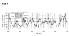
- Fig. 3 shows an example of a result of an estimation of the exhaust gas temperature (exhaust manifold temperature) in a transient operation, which is obtained through a test carried out in an exhaust gas test mode of a World Harmonized Transient Cycle (WHTC) by using the engine 1.
- WHTC World Harmonized Transient Cycle
- the exhaust manifold temperature (instantaneous value: before an annealing process), which is estimated by a process of estimating the exhaust gas temperature, is depicted by a solid line (a narrow line), the annealed exhaust manifold temperature (annealing value: after the annealing process), which is obtained by annealing the estimated exhaust manifold temperature (instantaneous value), is shown by a solid line (a thick line), and the actually measured exhaust manifold temperature is indicated by a dotted line.
- the estimated exhaust manifold temperature (annealing value) and the actually measured exhaust manifold temperature, it is noted that an estimated value very close to the actually measured value is obtained. In this example, there was an error of a maximum of ⁇ 30°C.
- the exhaust manifold temperature is estimated from the temperature increment by the adiabatic compression in the engine 1 and the temperature increment by the amount of lost heat/the diluted gas flow in the exhaust gas among the amount of the heat introduced into the cylinders (using Equation (12)). Therefore, the exhaust manifold temperature (the exhaust gas temperature) can be estimated with a high accuracy and a low processing load, by using only a typical sensor, which is reliable and conventionally installed in the engine, without installing an exhaust manifold temperature sensor.
- the estimated exhaust manifold temperature is very accurate even in a transient operational state as well as in a normal operational state. Further, with the engine 1, it is possible to simply acquire the exhaust loss rate by preparing in advance an exhaust loss rate map in which the number of revolutions and the amount of sprayed fuel of the engine are used as parameters.
- the exhaust manifold temperature may be easily changed by the adiabatic compression (the larger the difference between the exhaust manifold pressure and the intake manifold pressure by the turbocharger, the easier the change), and an error may easily occur in the estimation of the exhaust manifold temperature.
- the temperature increment of the adiabatic compression is taken into consideration in the process of estimating the exhaust gas temperature by the ECU 15, the estimation has a high accuracy even in the case of an engine equipped with a turbocharger.
- an error may easily occur in the estimation of the exhaust manifold temperature.
- the estimation has a high accuracy even in the case of an engine equipped with an EGR system.
- the exhaust manifold temperature is very important for an exhaust gas purification control as well as for the engine control (including a variable capacitance control of a turbocharger and an EGR control).
- an apparatus for estimating an exhaust gas temperature is embedded as one function of the ECU of the engine.
- the exhaust temperature estimating apparatus may be configured in another form, for example, the exhaust temperature estimating apparatus may be embedded in another ECU or may be configured as a single independent unit.
- the present invention is applied to a diesel internal combustion engine equipped with a variable capacitance type turbocharger and an EGR system.
- the present invention may be applied to other internal combustion engines, such as a gasoline engine, may be applied to an engine equipped with no turbocharger, and may be applied to an engine equipped with no EGR system.
- the turbocharger the present invention may be applied to even a fixed capacitance type turbocharger or a multistage supercharge type turbocharger.
- the present invention may be applied to even a Low Pressure Loop (LPL) EGR system.
- LPL Low Pressure Loop
- the exhaust loss rate is acquired by using the maps.
- the exhaust loss rate may be acquired according to another method.
- the exhaust loss rate may be calculated by using a previously prepared equation in which the number of revolutions of the engine or the amount of the sprayed fuel is used as a parameter.
- Equation (12) is established in order to estimate the exhaust manifold temperature by using the temperature increment caused by the adiabatic compression and the temperature increment caused by the amount of lost heat/diluted gas flow in the exhaust gas among the amount of heat introduced into the cylinders, and the exhaust manifold temperature is then estimated by using Equation (12).
- Equation (12) another estimation equation other than Equation (12) may be established, and the exhaust manifold temperature may be estimated according to another method using a map, etc.
- an exhaust gas temperature in an exhaust manifold can be estimated by using a temperature increment caused by an adiabatic compression in an internal combustion engine and a temperature increment caused by an amount of lost heat and a diluted gas flow in the exhaust gas among an amount of heat introduced into cylinders. Therefore, the present invention can be used for an exhaust gas temperature estimating apparatus, which can estimate an exhaust gas temperature with a high accuracy and a low processing load by using only a typical sensor usually installed in an internal combustion engine.
- engine 1a engine body 2a, 2b, 2c, 2d, 2e, 2f: cylinder 3a, 3b, 3c, 3d, 3e, 3f: injector 4: intake manifold 4a: intake manifold temperature sensor 5: exhaust manifold 5a: exhaust manifold pressure sensor 6: turbocharger 6a: compressor 6b: turbine 6c: nozzle vane 7: air cleaner 8a, 8b: intake passage 9: air flow sensor 10: intercooler 11: boost pressure sensor 12: exhaust passage 13: muffler 14: EGR system 14a: EGR passage 14b: EGR cooler 14c: EGR valve 14d: EGR gas flow sensor 15: ECU
Landscapes
- Engineering & Computer Science (AREA)
- Chemical & Material Sciences (AREA)
- Combustion & Propulsion (AREA)
- Mechanical Engineering (AREA)
- General Engineering & Computer Science (AREA)
- Physics & Mathematics (AREA)
- General Physics & Mathematics (AREA)
- Chemical Kinetics & Catalysis (AREA)
- Combined Controls Of Internal Combustion Engines (AREA)
- Exhaust-Gas Circulating Devices (AREA)
- Output Control And Ontrol Of Special Type Engine (AREA)
Applications Claiming Priority (2)
| Application Number | Priority Date | Filing Date | Title |
|---|---|---|---|
| JP2012194366A JP5373952B1 (ja) | 2012-09-04 | 2012-09-04 | 内燃機関の排気温度推定装置 |
| PCT/JP2013/068388 WO2014038278A1 (fr) | 2012-09-04 | 2013-07-04 | Dispositif d'estimation de température d'échappement d'un moteur à combustion interne |
Publications (3)
| Publication Number | Publication Date |
|---|---|
| EP2735719A1 true EP2735719A1 (fr) | 2014-05-28 |
| EP2735719A4 EP2735719A4 (fr) | 2014-10-01 |
| EP2735719B1 EP2735719B1 (fr) | 2016-05-04 |
Family
ID=49954948
Family Applications (1)
| Application Number | Title | Priority Date | Filing Date |
|---|---|---|---|
| EP13801455.0A Not-in-force EP2735719B1 (fr) | 2012-09-04 | 2013-07-04 | Dispositif d'estimation de température d'échappement d'un moteur à combustion interne |
Country Status (5)
| Country | Link |
|---|---|
| US (1) | US9127586B2 (fr) |
| EP (1) | EP2735719B1 (fr) |
| JP (1) | JP5373952B1 (fr) |
| CN (1) | CN104169554A (fr) |
| WO (1) | WO2014038278A1 (fr) |
Cited By (1)
| Publication number | Priority date | Publication date | Assignee | Title |
|---|---|---|---|---|
| WO2018004426A1 (fr) * | 2016-06-27 | 2018-01-04 | Scania Cv Ab | Détermination de température de carburant sous pression |
Families Citing this family (7)
| Publication number | Priority date | Publication date | Assignee | Title |
|---|---|---|---|---|
| CN106257253B (zh) * | 2015-06-19 | 2019-01-15 | 中国航发商用航空发动机有限责任公司 | 温度传感器信号修正方法和系统 |
| US9644548B2 (en) * | 2015-10-02 | 2017-05-09 | GM Global Technology Operations LLC | Exhaust system pressure estimation systems and methods |
| US9657670B2 (en) * | 2015-10-02 | 2017-05-23 | GM Global Technology Operations LLC | Exhaust system temperature estimation systems and methods |
| KR101789942B1 (ko) | 2016-12-30 | 2017-10-25 | 주식회사 현대케피코 | 차량 엔진의 배기온도 보정방법 |
| JP6534425B2 (ja) | 2017-06-27 | 2019-06-26 | 三菱電機株式会社 | 内燃機関の制御装置及び制御方法 |
| JP7435284B2 (ja) * | 2020-06-15 | 2024-02-21 | トヨタ自動車株式会社 | エンジン装置 |
| US11415074B1 (en) * | 2021-03-01 | 2022-08-16 | Ford Global Technologies, Llc | Engine cylinder head with integrated exhaust manifold and temperature sensor |
Family Cites Families (14)
| Publication number | Priority date | Publication date | Assignee | Title |
|---|---|---|---|---|
| JP3358449B2 (ja) * | 1996-07-09 | 2002-12-16 | 日産自動車株式会社 | 内燃機関の排気系圧力推定装置 |
| US6256992B1 (en) | 1998-05-27 | 2001-07-10 | Cummins Engine Company, Inc. | System and method for controlling a turbocharger to maximize performance of an internal combustion engine |
| US6067800A (en) * | 1999-01-26 | 2000-05-30 | Ford Global Technologies, Inc. | Control method for a variable geometry turbocharger in a diesel engine having exhaust gas recirculation |
| US6550464B1 (en) * | 2001-01-31 | 2003-04-22 | Cummins, Inc. | System for controlling engine exhaust temperature |
| JP2003307151A (ja) | 2002-04-15 | 2003-10-31 | Komatsu Ltd | 大気圧・排気温度推定方法 |
| JP4341240B2 (ja) | 2002-12-20 | 2009-10-07 | トヨタ自動車株式会社 | 内燃機関の制御装置 |
| JP4207565B2 (ja) * | 2002-12-27 | 2009-01-14 | 株式会社デンソー | 内燃機関の制御装置 |
| FR2894617B1 (fr) | 2005-12-13 | 2008-02-15 | Renault Sas | Procede d'estimation de temperature de gaz d'echappement avant turbine. |
| US7810476B2 (en) | 2007-03-06 | 2010-10-12 | Gm Global Technology Operations, Inc. | Method and apparatus for estimating exhaust temperature of an internal combustion engine |
| US7824099B2 (en) | 2007-11-29 | 2010-11-02 | Gm Global Technology Operations, Inc. | Accurate gas temperature estimation at transient conditions based on temperature sensor readings |
| JP2010101259A (ja) * | 2008-10-24 | 2010-05-06 | Toyota Motor Corp | 内燃機関の制御装置 |
| JP2012112326A (ja) * | 2010-11-25 | 2012-06-14 | Denso Corp | 非燃焼液体の噴射制御装置 |
| JP5392241B2 (ja) * | 2010-12-03 | 2014-01-22 | 三菱自動車工業株式会社 | 多気筒内燃機関 |
| JP5278464B2 (ja) * | 2011-02-08 | 2013-09-04 | トヨタ自動車株式会社 | 内燃機関の燃料噴射制御装置 |
-
2012
- 2012-09-04 JP JP2012194366A patent/JP5373952B1/ja not_active Expired - Fee Related
-
2013
- 2013-07-04 CN CN201380001877.6A patent/CN104169554A/zh active Pending
- 2013-07-04 EP EP13801455.0A patent/EP2735719B1/fr not_active Not-in-force
- 2013-07-04 US US14/127,056 patent/US9127586B2/en not_active Expired - Fee Related
- 2013-07-04 WO PCT/JP2013/068388 patent/WO2014038278A1/fr not_active Ceased
Cited By (3)
| Publication number | Priority date | Publication date | Assignee | Title |
|---|---|---|---|---|
| WO2018004426A1 (fr) * | 2016-06-27 | 2018-01-04 | Scania Cv Ab | Détermination de température de carburant sous pression |
| KR20190017934A (ko) * | 2016-06-27 | 2019-02-20 | 스카니아 씨브이 악티에볼라그 | 가압 연료 온도의 결정 |
| US11067021B2 (en) | 2016-06-27 | 2021-07-20 | Scania Cv Ab | Determination of pressurized fuel temperature |
Also Published As
| Publication number | Publication date |
|---|---|
| JP5373952B1 (ja) | 2013-12-18 |
| US20150032390A1 (en) | 2015-01-29 |
| EP2735719A4 (fr) | 2014-10-01 |
| EP2735719B1 (fr) | 2016-05-04 |
| US9127586B2 (en) | 2015-09-08 |
| JP2014047776A (ja) | 2014-03-17 |
| CN104169554A (zh) | 2014-11-26 |
| WO2014038278A1 (fr) | 2014-03-13 |
Similar Documents
| Publication | Publication Date | Title |
|---|---|---|
| EP2735719B1 (fr) | Dispositif d'estimation de température d'échappement d'un moteur à combustion interne | |
| EP2857664B1 (fr) | Procédé de détection de défaut | |
| EP1408331A2 (fr) | Procédé pour l'estimation d'oxydes d'azote en temps réel | |
| EP3179087B1 (fr) | Unité de détermination d'erreur | |
| US20100089371A1 (en) | Forced air induction system for internal combustion engine and abnormality diagnosis method for same system | |
| EP2927467B1 (fr) | Moteur à deux combustibles ou à gaz | |
| CN104919298A (zh) | 基于排气歧管压力的内燃发动机不点火检测 | |
| JP2012082766A (ja) | 内燃機関の筒内圧波形推定方法及び推定装置 | |
| JP6270210B2 (ja) | 筒内圧力センサ診断方法及び車両動作制御装置 | |
| JP5331613B2 (ja) | 内燃機関の筒内ガス量推定装置 | |
| EP3563048B1 (fr) | Surveillance de débitmètre d'air massique à l'aide de caractéristiques de flux d'air de compresseur de suralimentation dans un moteur à pistons opposés | |
| EP2474728B1 (fr) | Système de commande de recyclage des gaz d'échappement d'un moteur à combustion interne | |
| CN107152346B (zh) | 用于减少颗粒物质的发动机控制系统 | |
| US11293366B2 (en) | Data sensing and estimation | |
| EP1731890A1 (fr) | Procédé et appareil pour le calibrage de gain d'un capteur de pression de cylindre pour moteur à combustion interne | |
| US20190368435A1 (en) | High pressure egr flow model hybrid strategy | |
| KR101568643B1 (ko) | 내연 기관의 제어 장치 | |
| JP7373380B2 (ja) | 湿度センサ診断装置及び湿度センサ診断方法 | |
| JP2011196312A (ja) | 内燃機関の制御装置 | |
| Deuß et al. | Friction power measurements with a fired HDD engine–Method and initial results | |
| EP2647821A1 (fr) | Recirculation de gaz d'échappement pour de grands moteurs à combustion interne |
Legal Events
| Date | Code | Title | Description |
|---|---|---|---|
| PUAI | Public reference made under article 153(3) epc to a published international application that has entered the european phase |
Free format text: ORIGINAL CODE: 0009012 |
|
| 17P | Request for examination filed |
Effective date: 20131213 |
|
| AK | Designated contracting states |
Kind code of ref document: A1 Designated state(s): AL AT BE BG CH CY CZ DE DK EE ES FI FR GB GR HR HU IE IS IT LI LT LU LV MC MK MT NL NO PL PT RO RS SE SI SK SM TR |
|
| RIC1 | Information provided on ipc code assigned before grant |
Ipc: F02D 45/00 20060101AFI20140804BHEP Ipc: F02D 41/14 20060101ALI20140804BHEP |
|
| A4 | Supplementary search report drawn up and despatched |
Effective date: 20140828 |
|
| RIC1 | Information provided on ipc code assigned before grant |
Ipc: F02D 45/00 20060101AFI20140822BHEP Ipc: F02D 41/14 20060101ALI20140822BHEP |
|
| REG | Reference to a national code |
Ref country code: DE Ref legal event code: R079 Ref document number: 602013007357 Country of ref document: DE Free format text: PREVIOUS MAIN CLASS: F02D0045000000 Ipc: F01N0011000000 |
|
| RIC1 | Information provided on ipc code assigned before grant |
Ipc: G01K 13/02 20060101ALI20150901BHEP Ipc: F01N 11/00 20060101AFI20150901BHEP Ipc: F02D 41/14 20060101ALI20150901BHEP Ipc: G01M 15/10 20060101ALI20150901BHEP |
|
| GRAP | Despatch of communication of intention to grant a patent |
Free format text: ORIGINAL CODE: EPIDOSNIGR1 |
|
| DAX | Request for extension of the european patent (deleted) | ||
| INTG | Intention to grant announced |
Effective date: 20151117 |
|
| GRAS | Grant fee paid |
Free format text: ORIGINAL CODE: EPIDOSNIGR3 |
|
| GRAA | (expected) grant |
Free format text: ORIGINAL CODE: 0009210 |
|
| AK | Designated contracting states |
Kind code of ref document: B1 Designated state(s): AL AT BE BG CH CY CZ DE DK EE ES FI FR GB GR HR HU IE IS IT LI LT LU LV MC MK MT NL NO PL PT RO RS SE SI SK SM TR |
|
| REG | Reference to a national code |
Ref country code: GB Ref legal event code: FG4D |
|
| REG | Reference to a national code |
Ref country code: CH Ref legal event code: EP |
|
| REG | Reference to a national code |
Ref country code: AT Ref legal event code: REF Ref document number: 797116 Country of ref document: AT Kind code of ref document: T Effective date: 20160515 |
|
| REG | Reference to a national code |
Ref country code: IE Ref legal event code: FG4D |
|
| REG | Reference to a national code |
Ref country code: DE Ref legal event code: R096 Ref document number: 602013007357 Country of ref document: DE |
|
| REG | Reference to a national code |
Ref country code: NL Ref legal event code: MP Effective date: 20160504 |
|
| REG | Reference to a national code |
Ref country code: LT Ref legal event code: MG4D |
|
| PG25 | Lapsed in a contracting state [announced via postgrant information from national office to epo] |
Ref country code: NL Free format text: LAPSE BECAUSE OF FAILURE TO SUBMIT A TRANSLATION OF THE DESCRIPTION OR TO PAY THE FEE WITHIN THE PRESCRIBED TIME-LIMIT Effective date: 20160504 Ref country code: FI Free format text: LAPSE BECAUSE OF FAILURE TO SUBMIT A TRANSLATION OF THE DESCRIPTION OR TO PAY THE FEE WITHIN THE PRESCRIBED TIME-LIMIT Effective date: 20160504 Ref country code: LT Free format text: LAPSE BECAUSE OF FAILURE TO SUBMIT A TRANSLATION OF THE DESCRIPTION OR TO PAY THE FEE WITHIN THE PRESCRIBED TIME-LIMIT Effective date: 20160504 Ref country code: NO Free format text: LAPSE BECAUSE OF FAILURE TO SUBMIT A TRANSLATION OF THE DESCRIPTION OR TO PAY THE FEE WITHIN THE PRESCRIBED TIME-LIMIT Effective date: 20160804 |
|
| REG | Reference to a national code |
Ref country code: AT Ref legal event code: MK05 Ref document number: 797116 Country of ref document: AT Kind code of ref document: T Effective date: 20160504 |
|
| PG25 | Lapsed in a contracting state [announced via postgrant information from national office to epo] |
Ref country code: RS Free format text: LAPSE BECAUSE OF FAILURE TO SUBMIT A TRANSLATION OF THE DESCRIPTION OR TO PAY THE FEE WITHIN THE PRESCRIBED TIME-LIMIT Effective date: 20160504 Ref country code: SE Free format text: LAPSE BECAUSE OF FAILURE TO SUBMIT A TRANSLATION OF THE DESCRIPTION OR TO PAY THE FEE WITHIN THE PRESCRIBED TIME-LIMIT Effective date: 20160504 Ref country code: GR Free format text: LAPSE BECAUSE OF FAILURE TO SUBMIT A TRANSLATION OF THE DESCRIPTION OR TO PAY THE FEE WITHIN THE PRESCRIBED TIME-LIMIT Effective date: 20160805 Ref country code: ES Free format text: LAPSE BECAUSE OF FAILURE TO SUBMIT A TRANSLATION OF THE DESCRIPTION OR TO PAY THE FEE WITHIN THE PRESCRIBED TIME-LIMIT Effective date: 20160504 Ref country code: HR Free format text: LAPSE BECAUSE OF FAILURE TO SUBMIT A TRANSLATION OF THE DESCRIPTION OR TO PAY THE FEE WITHIN THE PRESCRIBED TIME-LIMIT Effective date: 20160504 Ref country code: PT Free format text: LAPSE BECAUSE OF FAILURE TO SUBMIT A TRANSLATION OF THE DESCRIPTION OR TO PAY THE FEE WITHIN THE PRESCRIBED TIME-LIMIT Effective date: 20160905 Ref country code: LV Free format text: LAPSE BECAUSE OF FAILURE TO SUBMIT A TRANSLATION OF THE DESCRIPTION OR TO PAY THE FEE WITHIN THE PRESCRIBED TIME-LIMIT Effective date: 20160504 |
|
| PG25 | Lapsed in a contracting state [announced via postgrant information from national office to epo] |
Ref country code: BE Free format text: LAPSE BECAUSE OF NON-PAYMENT OF DUE FEES Effective date: 20160731 Ref country code: IT Free format text: LAPSE BECAUSE OF FAILURE TO SUBMIT A TRANSLATION OF THE DESCRIPTION OR TO PAY THE FEE WITHIN THE PRESCRIBED TIME-LIMIT Effective date: 20160504 |
|
| PG25 | Lapsed in a contracting state [announced via postgrant information from national office to epo] |
Ref country code: DK Free format text: LAPSE BECAUSE OF FAILURE TO SUBMIT A TRANSLATION OF THE DESCRIPTION OR TO PAY THE FEE WITHIN THE PRESCRIBED TIME-LIMIT Effective date: 20160504 Ref country code: RO Free format text: LAPSE BECAUSE OF FAILURE TO SUBMIT A TRANSLATION OF THE DESCRIPTION OR TO PAY THE FEE WITHIN THE PRESCRIBED TIME-LIMIT Effective date: 20160504 Ref country code: EE Free format text: LAPSE BECAUSE OF FAILURE TO SUBMIT A TRANSLATION OF THE DESCRIPTION OR TO PAY THE FEE WITHIN THE PRESCRIBED TIME-LIMIT Effective date: 20160504 Ref country code: SK Free format text: LAPSE BECAUSE OF FAILURE TO SUBMIT A TRANSLATION OF THE DESCRIPTION OR TO PAY THE FEE WITHIN THE PRESCRIBED TIME-LIMIT Effective date: 20160504 Ref country code: CZ Free format text: LAPSE BECAUSE OF FAILURE TO SUBMIT A TRANSLATION OF THE DESCRIPTION OR TO PAY THE FEE WITHIN THE PRESCRIBED TIME-LIMIT Effective date: 20160504 |
|
| REG | Reference to a national code |
Ref country code: DE Ref legal event code: R097 Ref document number: 602013007357 Country of ref document: DE |
|
| PG25 | Lapsed in a contracting state [announced via postgrant information from national office to epo] |
Ref country code: BE Free format text: LAPSE BECAUSE OF FAILURE TO SUBMIT A TRANSLATION OF THE DESCRIPTION OR TO PAY THE FEE WITHIN THE PRESCRIBED TIME-LIMIT Effective date: 20160504 Ref country code: PL Free format text: LAPSE BECAUSE OF FAILURE TO SUBMIT A TRANSLATION OF THE DESCRIPTION OR TO PAY THE FEE WITHIN THE PRESCRIBED TIME-LIMIT Effective date: 20160504 Ref country code: AT Free format text: LAPSE BECAUSE OF FAILURE TO SUBMIT A TRANSLATION OF THE DESCRIPTION OR TO PAY THE FEE WITHIN THE PRESCRIBED TIME-LIMIT Effective date: 20160504 Ref country code: SM Free format text: LAPSE BECAUSE OF FAILURE TO SUBMIT A TRANSLATION OF THE DESCRIPTION OR TO PAY THE FEE WITHIN THE PRESCRIBED TIME-LIMIT Effective date: 20160504 |
|
| REG | Reference to a national code |
Ref country code: CH Ref legal event code: PL |
|
| PLBE | No opposition filed within time limit |
Free format text: ORIGINAL CODE: 0009261 |
|
| STAA | Information on the status of an ep patent application or granted ep patent |
Free format text: STATUS: NO OPPOSITION FILED WITHIN TIME LIMIT |
|
| PG25 | Lapsed in a contracting state [announced via postgrant information from national office to epo] |
Ref country code: MC Free format text: LAPSE BECAUSE OF FAILURE TO SUBMIT A TRANSLATION OF THE DESCRIPTION OR TO PAY THE FEE WITHIN THE PRESCRIBED TIME-LIMIT Effective date: 20160504 |
|
| 26N | No opposition filed |
Effective date: 20170207 |
|
| PG25 | Lapsed in a contracting state [announced via postgrant information from national office to epo] |
Ref country code: FR Free format text: LAPSE BECAUSE OF NON-PAYMENT OF DUE FEES Effective date: 20160801 Ref country code: LI Free format text: LAPSE BECAUSE OF NON-PAYMENT OF DUE FEES Effective date: 20160731 Ref country code: CH Free format text: LAPSE BECAUSE OF NON-PAYMENT OF DUE FEES Effective date: 20160731 |
|
| REG | Reference to a national code |
Ref country code: FR Ref legal event code: ST Effective date: 20170331 |
|
| REG | Reference to a national code |
Ref country code: IE Ref legal event code: MM4A |
|
| PG25 | Lapsed in a contracting state [announced via postgrant information from national office to epo] |
Ref country code: SI Free format text: LAPSE BECAUSE OF FAILURE TO SUBMIT A TRANSLATION OF THE DESCRIPTION OR TO PAY THE FEE WITHIN THE PRESCRIBED TIME-LIMIT Effective date: 20160504 |
|
| PG25 | Lapsed in a contracting state [announced via postgrant information from national office to epo] |
Ref country code: IE Free format text: LAPSE BECAUSE OF NON-PAYMENT OF DUE FEES Effective date: 20160704 |
|
| PG25 | Lapsed in a contracting state [announced via postgrant information from national office to epo] |
Ref country code: LU Free format text: LAPSE BECAUSE OF NON-PAYMENT OF DUE FEES Effective date: 20160704 |
|
| PGFP | Annual fee paid to national office [announced via postgrant information from national office to epo] |
Ref country code: GB Payment date: 20170724 Year of fee payment: 5 |
|
| PG25 | Lapsed in a contracting state [announced via postgrant information from national office to epo] |
Ref country code: CY Free format text: LAPSE BECAUSE OF FAILURE TO SUBMIT A TRANSLATION OF THE DESCRIPTION OR TO PAY THE FEE WITHIN THE PRESCRIBED TIME-LIMIT Effective date: 20160504 Ref country code: HU Free format text: LAPSE BECAUSE OF FAILURE TO SUBMIT A TRANSLATION OF THE DESCRIPTION OR TO PAY THE FEE WITHIN THE PRESCRIBED TIME-LIMIT; INVALID AB INITIO Effective date: 20130704 |
|
| PG25 | Lapsed in a contracting state [announced via postgrant information from national office to epo] |
Ref country code: MT Free format text: LAPSE BECAUSE OF NON-PAYMENT OF DUE FEES Effective date: 20160731 Ref country code: MK Free format text: LAPSE BECAUSE OF FAILURE TO SUBMIT A TRANSLATION OF THE DESCRIPTION OR TO PAY THE FEE WITHIN THE PRESCRIBED TIME-LIMIT Effective date: 20160504 Ref country code: IS Free format text: LAPSE BECAUSE OF FAILURE TO SUBMIT A TRANSLATION OF THE DESCRIPTION OR TO PAY THE FEE WITHIN THE PRESCRIBED TIME-LIMIT Effective date: 20160504 |
|
| PG25 | Lapsed in a contracting state [announced via postgrant information from national office to epo] |
Ref country code: BG Free format text: LAPSE BECAUSE OF FAILURE TO SUBMIT A TRANSLATION OF THE DESCRIPTION OR TO PAY THE FEE WITHIN THE PRESCRIBED TIME-LIMIT Effective date: 20160504 |
|
| PG25 | Lapsed in a contracting state [announced via postgrant information from national office to epo] |
Ref country code: AL Free format text: LAPSE BECAUSE OF FAILURE TO SUBMIT A TRANSLATION OF THE DESCRIPTION OR TO PAY THE FEE WITHIN THE PRESCRIBED TIME-LIMIT Effective date: 20160504 Ref country code: TR Free format text: LAPSE BECAUSE OF FAILURE TO SUBMIT A TRANSLATION OF THE DESCRIPTION OR TO PAY THE FEE WITHIN THE PRESCRIBED TIME-LIMIT Effective date: 20160504 |
|
| GBPC | Gb: european patent ceased through non-payment of renewal fee |
Effective date: 20180704 |
|
| PG25 | Lapsed in a contracting state [announced via postgrant information from national office to epo] |
Ref country code: GB Free format text: LAPSE BECAUSE OF NON-PAYMENT OF DUE FEES Effective date: 20180704 |
|
| PGFP | Annual fee paid to national office [announced via postgrant information from national office to epo] |
Ref country code: DE Payment date: 20190729 Year of fee payment: 7 |
|
| REG | Reference to a national code |
Ref country code: DE Ref legal event code: R119 Ref document number: 602013007357 Country of ref document: DE |
|
| PG25 | Lapsed in a contracting state [announced via postgrant information from national office to epo] |
Ref country code: DE Free format text: LAPSE BECAUSE OF NON-PAYMENT OF DUE FEES Effective date: 20210202 |