EP2735733A1 - Magnus-windturbinengenerator mit vertikaler achse - Google Patents
Magnus-windturbinengenerator mit vertikaler achse Download PDFInfo
- Publication number
- EP2735733A1 EP2735733A1 EP12817685.6A EP12817685A EP2735733A1 EP 2735733 A1 EP2735733 A1 EP 2735733A1 EP 12817685 A EP12817685 A EP 12817685A EP 2735733 A1 EP2735733 A1 EP 2735733A1
- Authority
- EP
- European Patent Office
- Prior art keywords
- axis
- barrel
- electric
- wind power
- barrels
- Prior art date
- Legal status (The legal status is an assumption and is not a legal conclusion. Google has not performed a legal analysis and makes no representation as to the accuracy of the status listed.)
- Withdrawn
Links
- 238000009987 spinning Methods 0.000 claims abstract description 75
- 230000001276 controlling effect Effects 0.000 description 85
- NJPPVKZQTLUDBO-UHFFFAOYSA-N novaluron Chemical compound C1=C(Cl)C(OC(F)(F)C(OC(F)(F)F)F)=CC=C1NC(=O)NC(=O)C1=C(F)C=CC=C1F NJPPVKZQTLUDBO-UHFFFAOYSA-N 0.000 description 14
- 238000005304 joining Methods 0.000 description 11
- 238000004519 manufacturing process Methods 0.000 description 10
- 230000000694 effects Effects 0.000 description 9
- 230000007246 mechanism Effects 0.000 description 9
- 230000008014 freezing Effects 0.000 description 8
- 238000007710 freezing Methods 0.000 description 8
- 239000000463 material Substances 0.000 description 8
- 230000009471 action Effects 0.000 description 7
- 238000009434 installation Methods 0.000 description 7
- 230000006378 damage Effects 0.000 description 5
- 238000012423 maintenance Methods 0.000 description 5
- 230000002265 prevention Effects 0.000 description 4
- 230000003014 reinforcing effect Effects 0.000 description 4
- 230000008859 change Effects 0.000 description 3
- 230000007704 transition Effects 0.000 description 3
- 230000006866 deterioration Effects 0.000 description 2
- 238000000034 method Methods 0.000 description 2
- APTZNLHMIGJTEW-UHFFFAOYSA-N pyraflufen-ethyl Chemical compound C1=C(Cl)C(OCC(=O)OCC)=CC(C=2C(=C(OC(F)F)N(C)N=2)Cl)=C1F APTZNLHMIGJTEW-UHFFFAOYSA-N 0.000 description 2
- 230000004043 responsiveness Effects 0.000 description 2
- 238000003860 storage Methods 0.000 description 2
- 238000010276 construction Methods 0.000 description 1
- 230000005611 electricity Effects 0.000 description 1
- 230000007613 environmental effect Effects 0.000 description 1
- 230000000977 initiatory effect Effects 0.000 description 1
- 239000002184 metal Substances 0.000 description 1
- 230000009467 reduction Effects 0.000 description 1
- 230000001105 regulatory effect Effects 0.000 description 1
Images














Classifications
-
- F—MECHANICAL ENGINEERING; LIGHTING; HEATING; WEAPONS; BLASTING
- F03—MACHINES OR ENGINES FOR LIQUIDS; WIND, SPRING, OR WEIGHT MOTORS; PRODUCING MECHANICAL POWER OR A REACTIVE PROPULSIVE THRUST, NOT OTHERWISE PROVIDED FOR
- F03D—WIND MOTORS
- F03D3/00—Wind motors with rotation axis substantially perpendicular to the air flow entering the rotor
- F03D3/005—Wind motors with rotation axis substantially perpendicular to the air flow entering the rotor the axis being vertical
- F03D3/007—Wind motors with rotation axis substantially perpendicular to the air flow entering the rotor the axis being vertical using the Magnus effect
-
- F—MECHANICAL ENGINEERING; LIGHTING; HEATING; WEAPONS; BLASTING
- F05—INDEXING SCHEMES RELATING TO ENGINES OR PUMPS IN VARIOUS SUBCLASSES OF CLASSES F01-F04
- F05B—INDEXING SCHEME RELATING TO WIND, SPRING, WEIGHT, INERTIA OR LIKE MOTORS, TO MACHINES OR ENGINES FOR LIQUIDS COVERED BY SUBCLASSES F03B, F03D AND F03G
- F05B2240/00—Components
- F05B2240/20—Rotors
- F05B2240/201—Rotors using the Magnus-effect
-
- F—MECHANICAL ENGINEERING; LIGHTING; HEATING; WEAPONS; BLASTING
- F05—INDEXING SCHEMES RELATING TO ENGINES OR PUMPS IN VARIOUS SUBCLASSES OF CLASSES F01-F04
- F05B—INDEXING SCHEME RELATING TO WIND, SPRING, WEIGHT, INERTIA OR LIKE MOTORS, TO MACHINES OR ENGINES FOR LIQUIDS COVERED BY SUBCLASSES F03B, F03D AND F03G
- F05B2240/00—Components
- F05B2240/40—Use of a multiplicity of similar components
-
- Y—GENERAL TAGGING OF NEW TECHNOLOGICAL DEVELOPMENTS; GENERAL TAGGING OF CROSS-SECTIONAL TECHNOLOGIES SPANNING OVER SEVERAL SECTIONS OF THE IPC; TECHNICAL SUBJECTS COVERED BY FORMER USPC CROSS-REFERENCE ART COLLECTIONS [XRACs] AND DIGESTS
- Y02—TECHNOLOGIES OR APPLICATIONS FOR MITIGATION OR ADAPTATION AGAINST CLIMATE CHANGE
- Y02B—CLIMATE CHANGE MITIGATION TECHNOLOGIES RELATED TO BUILDINGS, e.g. HOUSING, HOUSE APPLIANCES OR RELATED END-USER APPLICATIONS
- Y02B10/00—Integration of renewable energy sources in buildings
- Y02B10/30—Wind power
-
- Y—GENERAL TAGGING OF NEW TECHNOLOGICAL DEVELOPMENTS; GENERAL TAGGING OF CROSS-SECTIONAL TECHNOLOGIES SPANNING OVER SEVERAL SECTIONS OF THE IPC; TECHNICAL SUBJECTS COVERED BY FORMER USPC CROSS-REFERENCE ART COLLECTIONS [XRACs] AND DIGESTS
- Y02—TECHNOLOGIES OR APPLICATIONS FOR MITIGATION OR ADAPTATION AGAINST CLIMATE CHANGE
- Y02E—REDUCTION OF GREENHOUSE GAS [GHG] EMISSIONS, RELATED TO ENERGY GENERATION, TRANSMISSION OR DISTRIBUTION
- Y02E10/00—Energy generation through renewable energy sources
- Y02E10/70—Wind energy
- Y02E10/74—Wind turbines with rotation axis perpendicular to the wind direction
Definitions
- the present invention relates to a vertical-axis-type Magnus-system wind power electric generator.
- a horizontal-axis-type propeller-system wind power electric generator is a system that allows, by a lift force generated on a propeller (a blade of a wing shape) by the airflow, an electric generator to rotate, and is the mainstream of the commercial wind power electric generation worldwide, but there are problems as below.
- Patent Document 1 a Magnus-system wind power electric generator of such a horizontal-axis type as is shown in Patent Document 1 has been proposed.
- This wind power electric generator is a system which, with a blade that generates a lift force being not of a wing shape as propeller system but of a column shape (hereafter called barrel), allows, by a Magnus force generated on a barrel when the barrel has been allowed to spin in the airflow, an electric generator to rotate. Since it is possible to control, by controlling of the spinning rotation number of this barrel, the Magnus force, it is possible to heighten the electric-generation efficiency in the low-wind-velocity region and, besides, destruction under a strong wind is thought to be less prone to happen.
- a blade of a barrel shape is, being of high rigidity and less prone to be disrupted compared with a blade of a wing shape, capable of being manufactured at a low cost as well because the manufacturing is easy.
- the characteristics of the wind power electric generator of a vertical-axis type because no influence of the wind direction is exerted, a following-up mechanism with respect to the wind direction becomes unnecessary. Moreover, since the electric-generator rotation axis is vertical, it is possible to install the electric-generation portion near the ground, and the maintainability is high compared with the horizontal-axis type. Further, since a high tower is not necessarily necessitated, a medium-sized machine or large-sized machine of high electric-generation capacity is capable of being installed on the rooftop of a building or house.
- the vertical-axis drag-force type is one that obtains a rotation force by a wind pressure of the airflow
- a representative one is the Savonius system.
- the Savonius system excels in self-startability and rotation torque in the low-wind-velocity area, but the tip speed ratio is in principle equal to or less than 1, and the efficiency in the medium-wind-velocity area or more is not good.
- a representative one of a vertical-axis lift-force type is the gyromill system or the Darius system. Because these possess, similarly to the horizontal-axis-type propeller system, blades of a wing shape, it is possible to allow the tip speed ratio to be equal to or more than 1, and the efficiency is good compared with the drag-force type.
- the efficiency is worse than a wind power electric generator of a horizontal-axis type and, particularly in a low-wind-velocity area such that the tip speed ratio becomes equal to or less than 1, the electric-generation capacity becomes low, and the self-startability is also bad.
- Patent Document 2 vertical-axis-type Magnus-system wind power electric generators as shown in Patent Document 2 and Patent Document 3 have been proposed.
- These wind power electric generators can be said to be wind power electric generators with ideal property in an environment as Japan, because no influence of the wind direction change is exerted because they are of a vertical-axis type, and it is possible to heighten the electric-generation capability in the low-wind-velocity area controlling the Magnus force through controlling of the barrel spinning rotation number and, besides, destruction even under a strong wind is less prone to happen because they are of Magnus system.
- a vertical-axis-type Magnus-system wind power electric generator because also possessing, in addition to the superiority of the maintenance cost that is the characteristic of the vertical-axis type, the superiority of the manufacturing cost that is the characteristic of the Magnus system, becomes capable of being manufactured and put into practice at a lower cost than existing wind power electric generators.
- the above-mentioned vertical-axis-type Magnus-system wind power electric generator has not been implemented at the point in time of the application of the present invention and, as a big technical problem towards the implementation of the Magnus-system wind power electric generator of a vertical-axis type, cited is that, on the upwind and downwind sides of the electric-generator rotation axis, the rotation torque of the electric-generator rotation axis generated by the Magnus force becomes reversed.
- the vertical-axis-type Magnus-system wind power electric generator mentioned in Patent Document 3 is characterized in that it comprises a measuring means of the wind direction, an azimuth angle measuring means of the barrel, and a measuring means of the wind velocity, where individually controlling, based on discrepancy between the wind direction and the barrel position, and the spinning rotation number of the barrel, the spinning rotation numbers of the barrels.
- An object of the present invention is, in consideration of the above-mentioned problems, to furnish a vertical-axis-type Magnus-system wind power electric generator such that the electric-generation efficiency is high with simple controlling.
- the 1 st aspect of the present invention is a vertical-axis-type Magnus-system wind power electric generator, a windmill part that has a longitudinal axis, and rotates by wind power on its longitudinal axis; and an electric generator that has a stator, and a rotator joined to said windmill part, wherein said windmill part has:
- the 2 nd aspect of the present invention is a vertical-axis-type Magnus-system wind power electric generator according to the 1 st aspect of the present invention, wherein said one barrel of said two barrels, which is on an inside, is arranged between said other barrel that is on an outside and said longitudinal axis.
- the 3 rd aspect of the present invention is a vertical-axis-type Magnus-system wind power electric generator according to the 2 nd aspect of the present invention, further comprising an airflow shielding means provided between said two barrels, in order to shield an airflow to said barrel of said two barrels that is on a downwind side.
- the 4 th aspect of the present invention is a vertical-axis-type Magnus-system wind power electric generator according to the 3 rd aspect of the present invention, wherein at least on a side end face within a surface of said airflow shielding means, a shape for allowing an airflow to diffuse or disperse is formed.
- the 5 th aspect of the present invention is a vertical-axis-type Magnus-system wind power electric generator according to the 1 st aspect of the present invention, comprising:
- the 6 th aspect of the present invention is a vertical-axis-type Magnus-system wind power electric generator according to the 1 st aspect of the present invention, comprising a current-rectifying plate provided at least either between said barrel set and said longitudinal axis, or on an outside of said supporting member.
- the 1 st aspect of the invention related to the present invention is a vertical-axis-type Magnus-system wind power electric generator according to the above-mentioned 1 st aspect of the present invention, wherein said rotator is joined with said longitudinal axis, and said longitudinal axis rotates along with rotation of said windmill part.
- the 2 nd aspect of the invention related to the present invention is a vertical-axis-type Magnus-system wind power electric generator according to the above-mentioned 1 st aspect of the present invention, comprising a pedestal provided on a lower side of said windmill part, wherein said rotator is joined with said windmill part, and said longitudinal axis is fixed to said pedestal.
- the 3 rd aspect of the invention related to the present invention is a vertical-axis-type Magnus-system wind power electric generator according to the above-mentioned 1 st aspect of the present invention, wherein said barrel sets are plurally provided, and said plural barrel sets are, in plan view, arranged around said longitudinal axis at equal intervals.
- the 4 th aspect of the invention related to the present invention is a vertical-axis-type Magnus-system wind power electric generator according to the above-mentioned 1 st aspect of the present invention, wherein said barrel sets are plurally provided, and said plural barrel sets are, in plan view, arranged around said longitudinal axis at equal intervals, comprising:
- the 5 th aspect of the invention related to the present invention is a vertical-axis-type Magnus-system wind power electric generator according to the above-mentioned 1 st aspect of the present invention, wherein said barrel sets are plurally provided, and said plural barrel sets are, in plan view, arranged around said longitudinal axis at equal intervals, comprising:
- the 6 th aspect of the invention related to the present invention is a vertical-axis-type Magnus-system wind power electric generator according to the above-mentioned 1 st aspect of the present invention, wherein on a surface of said barrel, dimple-shaped depressions or protuberances are formed.
- the 7 th aspect of the invention related to the present invention is a vertical-axis-type Magnus-system wind power electric generator according to the above-mentioned 1 st aspect of the present invention, wherein on a surface of said barrel, ribs are formed that are parallel with respect to said supporting axis, vertical, or helix-shaped.
- the 8 th aspect of the invention related to the present invention is a vertical-axis-type Magnus-system wind power electric generator according to the above-mentioned 1 st aspect of the present invention, wherein said barrel is of a hollow cylinder shape.
- the 9 th aspect of the invention related to the present invention is a vertical-axis-type Magnus-system wind power electric generator according to the above-mentioned 1 st aspect of the present invention, wherein said barrel is configured so as to be capable of being in a spinning-axis direction divided into multiple barrel portions, joining parts are provided that join respective barrel portions, and said supporting axis is provided at least either downward from said barrel portion arranged on a lowermost side, or upward from said barrel portion arranged on a uppermost side.
- the 10 th aspect of the invention related to the present invention is a vertical-axis-type Magnus-system wind power electric generator according to the above-mentioned 1 st aspect of the present invention, comprising:
- the 11 th aspect of the invention related to the present invention is a vertical-axis-type Magnus-system wind power electric generator according to the above-mentioned 1 st aspect of the present invention, comprising:
- the 12 th aspect of the invention related to the present invention is a vertical-axis-type Magnus-system wind power electric generator according to the 11 th aspect of the invention related to the present invention, wherein said electric-generator controlling part does not switch, in a case where the wind velocity that is detected is less than a second predetermined wind velocity that is slower than said first predetermined wind velocity, said electric generator to said power source.
- the 13 th aspect of the invention related to the present invention is a vertical-axis-type Magnus-system wind power electric generator according to the above-mentioned 1 st aspect of the present invention, comprising:
- the 14 th aspect of the invention related to the present invention is a vertical-axis-type Magnus-system wind power electric generator according to the above-mentioned 1 st aspect of the present invention, comprising:
- the 15 th aspect of the invention related to the present invention is a vertical-axis-type Magnus-system wind power electric generator according to the above-mentioned 1 st aspect of the present invention, wherein said supporting member is of a disk shape.
- the 16 th aspect of the invention related to the present invention is a vertical-axis-type Magnus-system wind power electric generator according to the above-mentioned 1 st aspect of the present invention, wherein said supporting member is formed so as to demonstrate a flywheel effect.
- the 17 th aspect of the invention related to the present invention is a vertical-axis-type Magnus-system wind power electric generator according to the 15 th or 16 th aspect of the invention related to the present invention, wherein in said supporting member, plural axis bearing parts for supporting said supporting axes of the barrels are formed, and on any of said plural axis bearing parts are selectively arranged said barrels.
- the 18 th aspect of the invention related to the present invention is a vertical-axis-type Magnus-system wind power electric generator according to the above-mentioned 1 st aspect of the present invention, wherein said supporting member has an arm-shaped member formed so as to carry out tying between said barrel set and said longitudinal axis, comprising an expanding-and-contracting part provided between said longitudinal axis and said barrel set, of said supporting member, wherein said expanding-and-contracting part has a spring member that carries out energization so as to contract a distance between said longitudinal axis and said barrel set, and on an occasion of electric generation, by a balance of an energization force of said spring member, and a centrifugal force generated on said two barrels by rotation around said longitudinal axis, the distance between said longitudinal axis and said barrel set changes.
- the 19 th aspect of the invention related to the present invention is a vertical-axis-type Magnus-system wind power electric generator according to the above-mentioned 15 st aspect of the present invention, comprising:
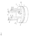
- Figure 1 is a perspective configuration view of the vertical-axis-type Magnus-system wind power electric generator in Embodiment 1 pertaining to the present invention.
- Figure 2 is a sectional configuration view between the XX' of Figure 1 .
- the vertical-axis-type Magnus-system wind power electric generator of present Embodiment 1 comprises the pedestal 1, and the windmill part 2 that is, being capable of rotating, arranged on the upper side of the pedestal 1.
- the electric generator 3 within the pedestal 1 is arranged the electric generator 3, the electric-generator rotation axis 3a is, in the electric generator 3, provided vertically upward, and this electric-generator rotation axis 3a is joining the electric generator 3 and the windmill part 2.
- This electric generator 3 is an electric generator of an inner-rotor type, the lower portion of the electric-generator rotation axis 3a is the rotator 100, and on its outside is provided the stator 101. And, the windmill part 2 rotates, thereby the electric-generator rotation axis 3a rotates, and the electric generator 3 performs the electric generation. Additionally, this electric-generator rotation axis 3a corresponds to one example of the longitudinal axis of the present invention.
- the supporting member 4 of a disk shape which is horizontally arranged, and at the center of the supporting member 4 is fixed the electric-generator rotation axis 3a.
- a total of the eight barrels 5 of a column shape is arranged.
- Figure 3 is a plan configuration view that shows the arrangement of the eight barrels 5.
- These eight barrels 5 are arranged, with each two being a set, such that their supporting axes 6 become vertical with respect to the surface of the supporting member 4.
- These two barrels 5 are arranged on a radius (shown with a two-dot chain line) in a direction towards the circumference from the center 4a (the electric-generator rotation axis 3a) of the supporting member 4. That is to say, between the barrel 5a of the barrel set 50, which is arranged on the outside, and the electric-generator rotation axis 3a is then arranged the barrel 5b on the inside.
- the four barrel sets 50 are arranged around the electric-generator rotation axis 3a at equal intervals, with this barrel 5a, which is arranged on the outside, and the barrel 5b, which is arranged on its inside, being the barrel set 50.
- the four barrels 5b of the four barrel sets 50 are arranged on a concentric circle with the center 4a, and the four barrels 5a are arranged on a concentric circle with the center 4a.
- the eight barrels 5 are by the supporting axes 6, being capable of spinning, pivotally supported on the axis bearing parts 4b formed in the supporting member 4.
- the barrel 5a on the inside and the barrel 5b on the outside are of the same size and, in a case where a distinction between each of them is not necessary, it will be mentioned as the barrel 5.
- the first gear 7 is provided being on the lower side of the barrel 5b and, on the supporting axis 6 of the barrel 5a on the outside, the second gear 8 is provided being on the lower side of the barrel 5a.
- These first gear 7 and second gear 8 are meshing with each other.
- the motor 9 on the supporting member 4 on the outer side of the barrel 5a is arranged the motor 9, and on the driving axis 9a of this motor 9 is provided the driving gear 10.
- the driving gear 10 and the second gear 8 are meshing with each other, and the driving force of the motor 9 is transmitted to the second gear 8 and the first gear 7.
- the motor 9 by allowing the motor 9 to drive, the barrels 5a and 5b then each spin, while the spinning directions of the barrel 5a and barrel 5b become opposite directions. Additionally, the electricity supplying to the motor 9 is performed by a slip ring. Moreover, the four barrel sets 50 are allowed to be of the same configuration. Moreover, so as to cover the first gear 7, the second gear 8 and the motor 9, on the supporting member 4 is provided the cover member 11.
- the spinning controlling part 12 that controls the spinning of the barrels 5 by the motor 9
- the rotation-number detecting part 16 that detects the rotation number of the electric-generator rotation axis 3a
- the switching part 14 that, in order to utilize by external electric power the electric generator 3 as a power source, switches the electric generator 3 to the power source
- the electric-generator controlling part 17 that controls the action of the electric-generator rotation axis 3a by running the switching part 14.
- the wind velocity meter 15, the temperature meter 18 and the snow sensing meter 19 are provided on the upper side of the cover member 11, the wind velocity meter 15, the temperature meter 18 and the snow sensing meter 19 are provided.
- one example of the stopping detecting part of the invention related to the present invention corresponds to the rotation-number detecting part 16 of the present embodiment.
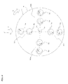
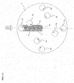
- Figure 4 is a plan configuration view for describing the action of the vertical-axis-type Magnus-system wind power electric generator of present Embodiment 1.
- the barrels 5a on the outside spin clockwise (the arrow B) in plan view
- the barrels 5b on the inside are spinning counterclockwise (the arrow C) in plan view.
- the direction of the wind is shown by the arrow A
- the barrel sets 50 are consecutively denoted clockwise by 50a on the upwind side, 50b, 50c and 50d.
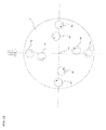
- Figures 5(a)-(d) are views that show the relations between the spinning of the barrels 5a and 5b in each of the barrel sets 50a-50b, the wind's direction and the Magnus forces.
- the Magnus force is proportional to the wind velocity, the spinning angular velocity of the barrel, and the diameter of the barrel.
- the Magnus force generated becomes large in comparison with the barrel 5b that is arranged on its downwind side. Therefore, the resultant force of the Magnus forces, which the two barrels 5a and 5b generate, is in the right direction, and via the supporting member 4 allows the electric-generator rotation axis 3a to rotate clockwise.
- the Magnus force generated becomes large in comparison with the barrel 5a that is arranged on its downwind side. Because of that, the barrel set 50a then moves in the left direction, and via the supporting member 4 allows the electric-generator rotation axis 3a to rotate clockwise.
- the force in the right direction is generated and, at the position of the barrel set 50c, the force in the left direction is generated. That is to say, when the barrel set 50 is in a region on the upwind side in comparison with the electric-generator rotation axis 3a, the Magnus force generated on the barrel set 50 is in a direction that allows the supporting member 4 to revolve clockwise around the electric-generator rotation axis 3a and, also when the barrel set 50 is in a region on the downwind side in comparison with the electric-generator rotation axis 3a, a Magnus force works in a direction that allows the supporting member 4 to revolve clockwise around the electric-generator rotation axis 3a. Because of that, the windmill part 2, in plan view, rotates clockwise (see the arrow D).
- the electric-generator rotation axis 3a rotates, and the electric generation is performed in the electric generator 3.
- the rotation number of the electric-generator rotation axis 3a is detected by the rotation-number detecting part 16 and, depending on that rotation number detected, the spinning controlling part 12 properly controls the rotation velocity of the spinning of the barrels 5.
- the rotation velocity detected by the wind velocity meter 15 the rotation velocity of the spinning of the barrels 5 may be controlled.
- the electric-generator controlling part 17 controls the switching part 14 and, utilizing the electric generator 3 as a power source, allows the electric-generator rotation axis 3a to, during a predetermined time, rotate at the first predetermined rotation velocity. Moreover, it is even more preferable that, at the same time, by the spinning controlling part 12, controlling is performed such that the barrels 5 spin at a rotation velocity equal to or more than the first rotation velocity.
- the windmill part 2 By carrying out controlling like this, even in a case where a weak wind of the first predetermined wind velocity or less has blown, the windmill part 2 thus easily rotates, and it is possible to carry out a transition to the electric-generation state.
- the wind velocity is less than the second predetermined wind velocity that is smaller than the first predetermined wind velocity, as there is almost no wind, it is concluded that the power becomes vain that allows the electric-generator rotation axis 3a to rotate, and controlling is performed so as not to drive the electric-generator rotation axis 3a. At this time, the spinning of the barrels 5 is also not performed.
- the above air second predetermined wind velocity is a wind velocity such that the electric-generator rotation axis 3a does not rotate even if the barrels 5 are allowed to spin and, for example, is the wind velocity 1m/s.
- the first predetermined wind velocity is a wind velocity such that the windmill part 2 does not rotate only with the spinning of the barrels 5, but that, by allowing the electric-generator rotation axis 3a to drive as mentioned above at the first rotation velocity, a transition to the electric-generation state is capable of being carried out and, for example is 3m/s.
- the spinning controlling part 12 every certain time, performs controlling so as to allow the barrels 5 to spin at a rotation velocity equal to or more than the second predetermined rotation velocity, for a time determined in advance.
- the second predetermined rotation velocity is a rotation velocity that is faster than the rotation velocity by the controlling at the time of electric generation.
- the rotation-number detecting part 16 may be found out that the electric-generator rotation axis 3a is rotating, with electric generation being carried out.
- the electric-generator controlling part 17 every certain time, runs the switching part 14 and switches the electric generator 3 to a power source, and performs controlling so as to allow the electric-generator rotation axis 3a to, during a predetermined time, drive at the second rotation velocity. Additionally, at this time, the spinning controlling part 12, every certain time, performs controlling so as to allow the barrels 5 to spin at a rotation velocity equal to or more than the second predetermined rotation velocity, for a time determined in advance.
- the electric-generator controlling part 17 every certain time, runs the switching part 14 and switches the electric generator 3 to a power source, and performs controlling so as to allow the electric-generator rotation axis 3a to, during a predetermined time, drive at the second rotation velocity. Additionally, at this time, by the spinning controlling part 12, controlling is performed that allows the barrels 5 to spin at a velocity equal to or less than the third predetermined rotation velocity.
- the above-mentioned second predetermined rotation velocity of the electric-generator rotation axis 3a is a low velocity.
- the third predetermined rotation velocity of the barrels 5 is a low velocity that is slower than the second predetermined rotation velocity.
- the Magnus force generated on the barrel 5a is in a direction that allows the supporting member 4 to revolve clockwise around the electric-generator rotation axis 3a
- the Magnus force generated on the barrel 5b is in a direction that allows the supporting member 4 to revolve counterclockwise around the electric-generator rotation axis 3a.
- Patent Document 3 that is a prior document, there have been problematic issues as follows. Energy loss becomes large because the spinning rotation numbers of the barrels are allowed to vary individually and besides frequently. Moreover, since there are moments of inertia in the barrels, in a case such that the wind velocity and the wind direction frequently vary, following-up of the controlling of the spinning rotation numbers of the barrels becomes impossible, and there is a possibility that the electric-generation efficiency will deteriorate. The moment of inertia of the barrel becomes an issue particularly in a case where the wind power electric generator is allowed to be increased in size.
- the vertical-axis-type Magnus-system wind power electric generator of the present embodiment by devising the arrangement and spinning directions of the barrels, no influence of the wind direction is exerted, the electric-generation efficiency is high, the startability is excellent, the electric generation is capable of being carried out in a broad wind velocity area, the safety with respect to a strong wind is high, the size-increasing is easy, the installation on the rooftop of a building, house or the like is capable of being carried out, or the manufacturing and putting-into-practice at a low cost becomes capable of being carried out.
- the vertical-axis-type Magnus-system wind power electric generator in Embodiment 2 is the same as that of Embodiment 1 in the basic configuration, but is different for instance in the configuration of the supporting member that supports the barrels with the lower sides, and in the point that the upper-side supporting member is appended that supports the barrels with the upper sides. Because of that, descriptions are given mainly on these points of difference. Additionally, identical symbols have been assigned regarding configurations similar to those of Embodiment 1.
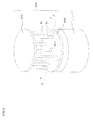
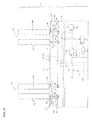
- Figure 6 is a perspective configuration view of the vertical-axis-type Magnus-system wind power electric generator of present Embodiment 2.
- Figure 7 is a sectional configuration view between the ZZ' of Figure 6 . Additionally, in Figure 6 and Figure 7 , the spinning controlling part 12, the rotation-number detecting part 16, the switching part 14, the electric-generator controlling part 17, the wind velocity meter 15, the temperature meter 18, and the snow sensing meter 19 are omitted.
- the disk-shaped upper-side supporting member 606 for supporting the upper sides of the barrels 5 is provided and, further, at the center of the windmill part 602 is provided the longitudinal axis 603.
- the lower part of this longitudinal axis 603 is allowed to be the rotator 100, and they are integrally formed in present Embodiment 2 but may be formed separately, being joined via the lower-side supporting member 604.
- the supporting axes 609 on the upper sides of the barrels 5 are provided the supporting axes 609 and these supporting axes 609 are, being capable of rotating, fitted to the axis bearing parts 606b of the upper-side supporting member 606. And, the longitudinal axis 603 is also, being capable of rotating, fitted to the axis bearing part 606c formed in the lower-side middle part of the upper-side supporting member 606.
- the lower-side supporting member 604 on the lower side is a hollow and disk-shaped member, and in its ceiling portion 604s are formed the axis bearing parts 604b that support the supporting axes 6. And, at the lower ends of the supporting axes 6 are provided the first gears 7 or second gears 8. That is to say, the supporting axes 6 are, between the barrels 5 and the first gears 7 or second gears 8, supported with the ceiling portion 604s of the lower-side supporting member 604.
- the driving gear 10 of the motor 9 has been meshing with the second gear 8 but, in present Embodiment 2, the driving gear 10 of the motor 9 is meshing with the first gear 7.
- Embodiment 1 the upper-side supporting member 606 and longitudinal axis 603 of the configuration of present Embodiment 2 may be applied to Embodiment 1.
- the upper-side supporting member 606 and the lower-side supporting member 604 have been of a disk shape but may be, the shape being not limited to this, of a cross shape.
- Figure 8 is a perspective configuration view of the vertical-axis-type Magnus-system wind power electric generator of a configuration like that.
- the lower-side supporting member 614 and the upper-side supporting member 616 are formed to be of a cross shape.
- the lower-side supporting member 614 and the upper-side supporting member 616 each have the middle parts 614a and 616a, and the arm parts 614b and 616b that have extended in all directions from the middle parts 614a and 616a.
- the angular degrees that are formed by the adjacent arm parts are allowed to be right angles. And, being sandwiched between the tip ends of the one arm part 614b and the one arm part 616b, the two barrels 5 are supported.
- FIG. 9 is a sectional configuration view viewed from the front of a vertical-axis-type Magnus-system wind power electric generator like this.
- the motor 9 is provided in every supporting axis 6 and, at the supporting axes 6, neither the first gears 7 nor the second gears 8 are provided.
- Embodiment 3 pertaining to the present invention.
- the vertical-axis-type Magnus-system wind power electric generator of present Embodiment 3 is the same as that of Embodiment 1 in the basic configuration, but is different in the configuration that allows the barrels 5 to spin. Because of that, descriptions are given mainly on these points of difference. Additionally, identical symbols have been assigned regarding configurations similar to those of Embodiment 1.
- the motor 9 that allows the barrels 5 to spin is provided in every barrel set 50, and four ones have been arranged in total but, in present Embodiment 3, only one motor is provided, and the configuration is allowed to be that, with this one motor, all the barrels 5 are allowed to spin.
- Figure 10 is a front sectional configuration view of the vertical-axis-type Magnus-system wind power electric generator of present Embodiment 3.
- Figure 11 is a sectional configuration view between the YY' of Figure 10 .
- the motor 9 that corresponds to each of the barrel sets 50 is not provided, and the one motor 20 is provided.
- the transmitting mechanism from this motor 20 to the barrels 5 corresponds to one example of the second transmitting mechanism of the invention related to the present invention. In what follows, descriptions are given regarding this transmitting mechanism.
- the driving gear 21 is provided at the tip end of the motor axis 20a that is arranged in the vertically upward direction from the motor 20, the driving gear 21 is provided. And, so as to mesh with the plural first gears 7, in the middle of those is arranged the middle gear 22, and this middle gear 22 and the driving gear 21 are meshing with each other. Additionally, the middle gear 22 is, by the supporting axis 22a, being capable of rotating, pivotally supported on the axis bearing part 4b of the supporting member 4, and the supporting axis 22a is provided on the center 4a of the supporting member 4.
- the motor axis 20a rotates, by the driving gear 21 that is fixed to the motor axis 20a the middle gear 22 rotates, and the four first gears 7 rotate. And, the second gear 8 also rotates that is meshing with each of the first gears 7.
- Embodiment 4 The configuration of present Embodiment 4 is that as that of Embodiment 3 all the barrels are allowed to spin by one motor, but is different in the point that the motor 9 is arranged on the pedestal side. Because of that, descriptions are given mainly on these points of difference. Additionally, identical symbols have been assigned regarding configurations similar to those of above-mentioned Embodiments 1 and 2.
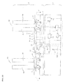
- Figure 12 is a sectional configuration view viewed from the front of the vertical-axis-type Magnus-system wind power electric generator of Embodiment 4 pertaining to the present invention. Additionalty, in Figure 12 , the spinning controlling part 12, the rotation-number detecting part 16, the switching part 14, the electric-generator controlling part 17, the wind velocity meter 15, the temperature meter 18, and the snow sensing meter 19 are omitted.
- the upper-side supporting member 606, the lower-side supporting member 644, and the longitudinal axis 603 are provided as the windmill part 602 of the configuration of Embodiment 2 and, with the axis bearing parts 644b formed in the ceiling portion 644s of the lower-side supporting member 644, the supporting axes 6 are supported.
- the middle gear 22 within the lower-side supporting member 644 is arranged the middle gear 22.
- the longitudinal axis 603, and the middle gear 22 is not fixed to the longitudinal axis 603, and is configured so as to freely rotate with respect to the longitudinal axis 603.
- the in-pedestal middle gear 615 coaxially with the middle gear 22 is provided the in-pedestal middle gear 615.
- this in-pedestal middle gear 615 the configuration of which is also that within the through hole formed in its middle is arranged the longitudinal axis 603, is not fixed to the longitudinal axis 603, and is configured so as to freely rotate with respect to the longitudinal axis 603.
- the in-pedestal middle gear 615 and the middle gear 22 are joined by the joining member 618, and rotate at the same time.
- the driving gear 617 So as to mesh with the in-pedestal middle gear 615 that has joined with the middle gear 22 like this is provided the driving gear 617, and this driving gear 617 is fixed to the driving axis 9a of the motor 9.
- Embodiments 3 and 4 because in the configurations of Embodiments 3 and 4 only one motor needs to be provided, they are useful with respect to a small-sized wind power electric generator. Additionally, in a case of a large size, it is more preferable that in every barrel set 50 is provided the motor 9.
- the vertical-axis-type Magnus-system wind power electric generator in Embodiment 5 is the same as that of Embodiment 4 in the basic configuration, but is different in the point that, in present Embodiment 5, differently from Embodiment 4, an electric generator of an outer-rotor type is utilized. Because of that, descriptions are given mainly on these points of difference.
- Figure 13 is a sectional configuration view viewed from the front of the vertical-axis-type Magnus-system wind power electric generator of present Embodiment 5.
- the longitudinal axis 623 in the vertical-axis-type Magnus-system wind power electric generator of present Embodiment 5, in the middle of the windmill part 622 is provided the longitudinal axis 623.
- This longitudinal axis 623 is fixed to the pedestal 1, and the windmill part 622 is configured so as to freely rotate with respect to the longitudinal axis 623.
- the lower-side supporting member 654 and the upper-side supporting member 656 are provided that are configured so as to freely rotate with respect to the longitudinal axis 623.
- the axis bearing parts 656b are formed that support the supporting axes 609 on the upper side, and the lower-side supporting member 654 supports, with the axis bearing parts 654b provided in its ceiling portion 654s, the supporting axes 6 on the lower side.
- the electric generator 624 is arranged on the upper side of the lower-side supporting member 654.
- This electric generator 624 is an electric generator of an outer-rotor type that has the stator 624a provided in the middle, and the rotator 624b provided in its surrounding.
- the stator 624a is configured by one part of the longitudinal axis 623, and the rotator 624b is fixed on the lower-side supporting member 614.
- the rotator 624b of the electric generator 624 rotates, and the electric generation is performed.
- an electric generator of an outer-rotor type may be utilized.
- the spinning controlling part 12, the rotation-number detecting part 16, the switching part 14, the electric-generator controlling part 17, the wind velocity meter 15, the temperature meter 18, and the snow sensing meter 19 are omitted but, in the case of the present embodiment, the rotation-number detecting part detects the rotation of the rotator 624b, and the electric-generator controlling part, by allowing the switching part 14 to act, then allows the rotator 624b to move.
- the windmill part 622 is not rotating, controlling similar to that of Embodiment 1 is performed but, instead of allowing the electric-generator rotation axis 3a, that is to say the rotator 100 to rotate, in the present embodiment, the rotator 624b is then allowed to rotate.
- the vertical-axis-type Magnus-system wind power electric generator in Embodiment 6 pertaining to the present invention.
- the vertical-axis-type Magnus-system wind power electric generator in present Embodiment 6 is the same as that of Embodiment 1 in the basic configuration, but is different in the controlling method. Because of that, descriptions are given mainly on these points of difference. Additionally, identical symbols have been assigned regarding configurations similar to those of Embodiment 1.
- Figure 14 is a sectional configuration view viewed from the front of the vertical-axis-type Magnus-system wind power electric generator of present Embodiment 6.
- the wind velocity meter 15 is not provided, and the stopping-time detecting part 13 is provided that detects, based on the rotation number detected with the rotation-number detecting part 16, the time for which the electric-generator rotation axis 3a is stopping.
- the electric-generator controlling part 17 every certain time, runs the switching part 14 and switches the electric generator 3 to a power source, and performs controlling so as to allow the electric-generator rotation axis 3a to, during a predetermined time, drive at the first predetermined rotation velocity. Additionally, it is even more preferable that, at this time, by the spinning controlling part 12, controlling is performed that allows the barrels 5 to spin at a velocity equal to or more than the first predetermined rotation velocity.
- the windmill part 2 By carrying out controlling like this, even in a case where a weak wind has blown, the windmill part 2 thus easily rotates, and heightens the possibility that it is possible to carry out a transition to the electric-generation state.
- the spinning controlling part 12 every certain time, performs controlling so as to allow the barrels 5 to spin at a rotation velocity equal to or more than the second predetermined rotation velocity, for a time determined in advance.
- the second predetermined rotation velocity is a rotation velocity that is faster than the rotation velocity by the controlling at the time of electric generation.
- the electric-generator controlling part 17 every certain time, runs the switching part 14 and switches the electric generator 3 to a power source, and performs controlling so as to allow the electric-generator rotation axis 3a to, during a predetermined time, drive at the second rotation velocity.
- the spinning controlling part 12 every certain time, performs controlling so as to allow the barrels 5 to spin at a rotation velocity equal to or more than the second predetermined rotation velocity, for a time determined in advance.
- the electric-generator controlling part 17 runs the switching part 14 and switches the electric generator 3 to a power source, and performs controlling so as to allow the electric-generator rotation axis 3a to, during a predetermined time, drive at the second predetermined rotation velocity. Additionally, at this time, by the spinning controlling part 12, controlling is performed that allows the barrels 5 to spin at a velocity equal to or less than the third predetermined rotation velocity.
- the above-mentioned second predetermined rotation velocity of the electric-generator rotation axis 3a is a low velocity
- the third predetermined rotation velocity of the barrels 5 is a low velocity that is slower than the second predetermined rotation velocity.
- the temperature meter 18 and the snow sensing meter 19, in Embodiments 1-6 have been provided, but need not be provided in a district where there is neither snow-coverage nor freezing.
- the actions for the snow-coverage prevention or freezing prevention may be switched to be turned on and off.
- Embodiments 1, 3 and 6 the whole of the upper side of the supporting member 4 has been covered by the cover member 11 but, as in the variant example of Embodiment 1 shown in Figure 15 , so as to at least cover only the downward first gears 7, second gears 8 and motors 9 of the barrel sets 50 may be provided the cover members 111.
- the vertical-axis-type Magnus-system wind power electric generator in Embodiment 7 is the same as that of Embodiment 1 in the basic configuration, but differs in the shape of the supporting member, and differs in the point that it is configured so as to be capable of expanding and contracting. Because of that, descriptions are given mainly on these points of difference. Additionally, identical symbols have been assigned regarding configurations similar to those of Embodiment 1.
- Figure 16 is a perspective configuration view of the vertical-axis-type Magnus-system wind power electric generator of present Embodiment 7.
- the supporting member 40 of present Embodiment 7 is of a cross shape in plan view, from the middle part 41 to which the electric-generator rotation axis 3a is fixed, so as to protrude in all directions are extending the arm parts 42, and at the tip ends of those are arranged the barrel sets 50 (the barrels 5a and 5b). And, the angular degrees the adjacent arm parts 42 form are allowed to be right angles.
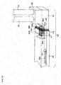
- Figure 17 is an enlarged configuration view of a neighborhood of the expanding-and-contracting part 43. Additionally, in Figure 17 , the state is shown where the expanding-and-contracting part 43 has expanded.
- the expanding-and-contracting part 43 has the multiple frame-shaped members 44.
- the number of the frame-shaped members is allowed to be four, and the symbols 44a, 44b, 44c and 44d are consecutively assigned from the side of the tip end 42a of the arm part 42.
- These frame-shaped members 44a, 44b, 44c and 44d consecutively become large in size, and are configured such that the frame-shaped member 44a is inserted in the adjoining frame-shaped member 44b, the frame-shaped member 44b is inserted in the adjoining frame-shaped member 44c, and the frame-shaped member 44c is inserted in the adjoining frame-shaped member 44d.
- the edge part S of the frame-shaped member 44a on the side of the middle part 41 is formed so as to be engaged with the edge part T of the frame-shaped member 44b on the side of the tip end 42a, and they are configured so as not to be alienated.
- the same is also true between other frame-shaped members.
- the frame-shaped member 44a is fixed to the outside portion 45 on the side of the tip end 42a in comparison with the expanding-and-contracting part 43 of the arm part 42
- the frame-shaped member 44d is fixed to the inside portion 46 on the side of the middle part 41 in comparison with the expanding-and-contracting part 43 of the arm part 42.
- the protuberant parts 45a and 46a in respective internal parts are formed the protuberant parts 45a and 46a, and to the protuberant parts 45a and 46a is fixed the spring member 47.
- the spring member 47 both ends of which are fixed to the protuberant parts 45a and 46a respectively, carries out energization such that the expanding-and-contracting part 43 contracts.
- the reinforcing member 56 that joins the outside portion 45 and the inside portion 46 is provided in the internal part of the arm part 42.
- This reinforcing member 56 is a plate-shaped member, and the one end is fixed to the outside portion 45.
- the longhole 56a is formed, and the pin 57 is provided that fits to that longhole 56a and is fixed to the inside portion 46.
- This pin 57 is, so as not to fall out from the longhole 56a, formed such that the upper end is large. That is to say, the reinforcing member 56 is configured so as to be capable of sliding.
- the cover member 48 is provided that covers the first gear 7, second gear 8, motor 9, driving gear 10 and so forth described in Embodiment 1. And, on that are arranged the barrels 5a and 5b.
- the expanding-and-contracting part 43 has been formed with four frame-shaped members, but is not limited to this.
- the airflow shielding plate 49 may be provided that corresponds to one example of the airflow shielding means of the present invention.
- Figure 19(a) is a perspective configuration view shows, citing Embodiment 1 as an example, the airflow shielding plate 49 that is provided between the barrel 5a and the barrel 5b.
- Figure 19(b) is a view that shows the relation between the spinning of the barrels 5a and 5b of the barrel set 50a and the Magnus forces that arise by the wind's direction.
- this airflow shielding plate 49 a shape so as to allow the airflow to diffuse or disperse is formed and, for example, it is enough that the concave part 49a as shown in Figure 19(c) is formed.
- a shape so as to allow the airflow to diffuse or disperse is formed on the side end face 49b of the airflow shielding plate 49.
- the fiber-shaped protruding parts 49c as shown in Figure 19(d) are formed.
- the plural protruding parts 49c are obliquely formed with respect to the horizontal direction such that the intervals between the adjacent protruding parts 49c become large or small.
- the most upward protruding part 49c of Figure 19(d) is obliquely formed such that in comparison with the paper-face front becomes low the depth side
- the second protruding part 49c on its lower side is obliquely formed such that in comparison with the paper-face front becomes high the depth side, and the interval between these two protruding parts 49c is becoming small as going in the paper-face depth direction.
- the third protruding part 49c is obliquely formed such that in comparison with the paper-face front becomes low the depth side, and the interval between the two second and third protruding parts 49c is becoming large as going in the paper-face depth direction.
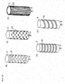
- the dimple-shaped depressions 51 may be formed on the surface of the barrel 5 of above-mentioned Embodiments 1-7.
- the protuberances 52 may be formed on the surface of the barrel 5 .
- the ribs 53 on the surface of the barrel 5 may be formed on the surface of the barrel 5 that are parallel with respect to the supporting axis 6.
- the ribs 54 may be formed that are vertical with respect to the supporting axis 6.
- the helix-shaped ribs 55 may be formed on the surface of the barrel 5 of above-mentioned Embodiments 1-7.
- Figure 21 is a view that shows the configuration of the barrel 105 of a configuration like this.
- the barrel 105 shown in Figure 21 is hollow, and at its center is arranged the supporting axis 106. This supporting axis 106 and the barrel 105 are joined by the supporting arms 107.
- the barrel 5 is one member but, for instance in a case where the length is long, may be configured to be divided in consideration of portability.
- Figure 22 is an exploded perspective configuration view of the barrel 630 like this.
- the barrel 630 has the two cylinder parts 631 and 632 consecutively arranged from above, the upper-supporting-axis part 633 that is arranged on the upper side of the cylinder part 631, the connecting part 634 that carries out connecting between the cylinder part 631 and the cylinder part 632, and the lower-supporting-axis part 635 that is arranged on the lower side of the cylinder part 632.
- These cylinder parts 631 and 632 are hollow, and at four spots for the upper and lower ones each are formed the through holes 631 a, 631 b, 632a and 632b for screw.
- the upper-supporting-axis part 633 has the upper supporting axis 633a, the fitting part 633b that fits to the cylinder part 631, and the column part 633c formed between the upper supporting axis 633a and the fitting part 633b, and in the fitting part 633b are formed the four screw holes 633d.
- the connecting part 634 has the fitting part 634a that fits to the inside of the cylinder part 631, the fitting part 634b that fits to the inside of the cylinder part 632, and the column part 634c formed between the fitting part 634a and the fitting part 634b. And, in the fitting part 634a, the four screw holes 634d are formed and, in the fitting part 634b, the four screw holes 634e are formed.
- the lower-supporting-axis part 635 has the lower supporting axis 635a, the fitting part 635b that fits to the inside of the cylinder part 632, and the column part 635c provided between the lower supporting axis 635a and the fitting part 635b, and in the fitting part 635b are formed the four screw holes 635d.
- These cylinder parts 631 and 632, and the column parts 633c, 634c and 635c are all of the same diameter.
- one example of the barrel portions of the present invention corresponds to the cylinder parts 631 and 632, or the column parts 633c, 634c and 635c.
- the barrel 630 is assembled.
- the upper supporting axis 633a corresponds to the supporting axis 609 on the upper side of the barrel 5 of Figure 7
- the lower supporting axis 635a corresponds to the supporting axis 6 of the barrel 5 of Figure 7 .
- Figure 23(a) is a perspective configuration view of the barrel 205 like this.
- Figure 23(b) is a perspective configuration view that shows the state where the barrel 205 has been divided.
- the barrel 205 is configured by the plural barrel parts 251, 252 and 253 consecutively arranged from above.
- the barrel part 251 positioned at the uppermost part has the joining axis 61 on its lower side
- the barrel part 252 positioned at the middle has the joining axis 62 provided on its upper side, and the joining axis 63 provided on its lower side.
- the barrel part 253 positioned at the lowermost part has the joining axis 64 provided on its upper side, and the supporting axis 65 provided on its lower side. And, the joining axes 61, 62, 63 and 64 are hollow, and the through holes 61a, 62a, 63a and 64a are formed respectively.
- the joining axis 61 of the barrel part 251 is fitted to the inside of the joining axis 62 of the barrel part 252 and, by putting, in the state where the positions of the through hole 61a and the through hole 62a have been adjusted, the pin 254 in the through holes 61a and 62a, the barrel part 251 and the barrel part 252 are fixed.
- the joining axis 63 of the barrel part 252 is fitted to the inside of the joining axis 64 of the barrel part 253 and, by putting, in the state where the positions of the through hole 63a and the through hole 64a have been adjusted, the pin 254 in the through holes 63a and 64a, the barrel part 252 and the barrel part 253 are fixed. Additionally, the first gear 7 and the second gear 8 are then arranged on the supporting axis 65.
- the upper supporting axis 633a and the lower supporting axis 635a are provided and, in Figure 23 , the supporting axis 65 on the lower side is provided, but a configuration may be that only a supporting axis on the upper side is provided (not shown). Moreover, also regarding the barrel 5 that is not divided, a configuration may be that it is supported only with the supporting axis 609 on the upper side (not shown).
- a supporting member of a disk shape is utilized, but a configuration may be made so as to demonstrate a flywheel effect. Specifically, it is possible to form the one with a metal and so forth so that the mass becomes heavy. Moreover, as shown in the supporting member 204 of Figure 24(a) , it is enough that the materials of the middle portion 204a and the periphery portion 204b are altered, and that, as the material of the periphery portion 204b, the one the mass per unit volume of which is heavy in comparison with the material of the middle portion 204a is utilized.
- the weight 605 on the whole lower side of the lower-side supporting member 604 (see Figure 6 ) may be arranged the weight 605 and, as shown in Figure 24(c) , in the surrounding of the lower side of the lower-side supporting member 604 may be arranged the weight 608.
- the one the mass per unit volume of which is heavy in comparison with the materials of the middle part 41 and the inside portion 46 may be utilized.
- the supporting member 400 of such a cross shape as is utilized in the above-mentioned variant example of Embodiment 2 of Figure 8 is shown in Figure 25(a) .
- This supporting member 400 is of a cross shape in plan view, and has the middle part 401 to which the electric-generator rotation axis 3a and the longitudinal axis 603 are fixed, and the arm parts 402 formed so as to protrude from the middle part 401 in all directions.
- the four barrel sets 50 have been provided, but the count may be equal to or less than three or, alternatively equal to or more than five. Additionally, at this time, it is more preferable that the plural barrel sets 50 are arranged in plan view around the electric-generator rotation axis 3a at equal intervals. Disposing them like this radially around the electric-generator rotation axis 3a at equal intervals it is possible to allow the varying weighting that arises on the electric-generator rotation axis 3a to level off. Moreover, by properly arranging the number of the barrel sets 50, it is possible to grow the rotation torque of the electric-generator rotation axis.
- the arrangement is carried out such that the angles each the adjoining barrel sets 50 and the electric-generator rotation axis 3a form become approximately 120 degrees. Additionally, from the viewpoint of the standardization of the varying weighting it is more preferable that they are arranged around the electric-generator rotation axis 3a at equal intervals, but the only one barrel set 50 may be arranged. Only one set may be provided.
- a configuration may be allowed to be that, in the supporting member of a disk shape of Embodiments 1-6, the plural axis bearing parts 4b such that the supporting axes 6 are capable of being arranged are formed to selectively arrange the barrels 5.
- Figure 27 is a plan configuration view of the supporting member 410.
- the supporting member 410 is at its center 410a fixed with the electric-generator rotation axis 3a, and are provided the axis bearing parts 411 that arrange the supporting axes 6 of the barrels 5 on the outside, being capable of rotating, and the axis bearing parts 412 that arrange the supporting axes 6 of the barrels 5 on the inside, being capable of rotating.
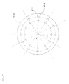
- the supporting member 410 shown in Figure 27 for the set of the axis bearing part 411 and the axis bearing part 412, twelve sets are formed. Moreover, the angular degrees (see a in the figure) that are formed by the adjacent lines which tie the set of the axis bearing parts 412 and 411 and the center 410a are all allowed to be equal.
- the supporting member 410 formed like this it is possible to carry out selection such that the one, two, three, four, six or twelve barrel sets 50 are utilized. Additionally, in the case of two, three, four or six, it is more preferable that each and all of the barrel sets 50 are arranged around the center 410a at equal intervals.
- the supporting axis 6 on the inside and the supporting axis 6 on the outside allowed to be one set also regarding the cover member 11, the holes are formed through which the twenty-four supporting axes 6 in total of twelve sets go.
- a frame structure may be provided that supports the windmill part so as to cover it.
- Figure 28 is a perspective configuration view that shows a configuration such that, to the configuration of Embodiment 2 that has been shown in Figure 6 , the frame structure 500 has been appended.
- the longitudinal axis 603 protrudes from the upper-side supporting member 606, and has the upper frame member 501 that supports the upper end of the longitudinal axis 603 being capable of rotating, and the three side frame parts 503 that join the upper frame member 501 and the pedestal 1.
- the upper frame member 501 is configured by the middle part 501 a where the longitudinal axis 603 is arranged, and the arm parts 501 b that expand from the middle part 501 a to the side frame parts 503.
- Figure 29 is a view that shows a configuration like that. As shown in Figure 29 , so as to hold the upper-side supporting member 606, in intermediate positions of the plural barrel sets, from the lower-side supporting member 604 are provided the longitudinal frames 660.
- Figure 30 is a plan configuration view of the vertical-axis-type Magnus-system wind power electric generator with the four barrel sets 50 arranged. As shown in Figure 30 , at intervals of 60 degrees in directions towards the center 4a, on the outside of the supporting member 4 are provided the current-rectifying plates 502. Directing the wind, by arranging like this the current-rectifying plates 502, in directions towards the longitudinal axis of the windmill part, the shielding quantities of the barrels on the downwind side become large, and it is possible to efficiently carry out the electric generation. Moreover, between the barrel sets 50, and the center 4a (agreeing with the longitudinal axis) may be provided current-rectifying plates.
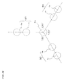
- the barrel set 50 of the above-mentioned embodiments for the barrel 5b, its center is arranged on the line that ties the barrel 5a and the center 4a (agreeing with the longitudinal axis) but, not being limited to this, it is enough that the arrangement is carried out between the barrel 5a and the center 4a. Yet, as shown in Figure 31 , it is more preferable that at least one part of the barrel 5b is contained within the region S.
- the region S is a region between the two tangential lines L and M at the outer periphery of the barrel 5a, which are parallel with a straight line that ties the barrel 5a and the longitudinal axis.
- the barrel 5b is, as shown in Figure 32 , arranged such that at least one part of it sits on the line that ties the barrel 5a and the center 4a of the longitudinal axis.
- the vertical-axis-type Magnus-system wind power electric generator of the present invention may be allowed to comprise a solar battery.
- an electric-power storing means for storing the electric power said electric generator has generated, or the electric power said solar battery has generated may be provided.
- said electric-power storing means the commercial electric source and the like, as the electric source that allows the barrels 5 to spin, or, the electric source on the occasion that the electric-generator controlling part 17 controls the switching part 14, and utilizes the electric generator 3 as a power source.
- the motor 9 that allows the barrels 5 to spin may be, not limited to an AC motor, a DC motor.
- a DC motor In a case where a DC motor is utilized, and besides as the electric-power storing means has been utilized a storage battery, it is possible to employ a direct current of the electric power stored in the storage battery as it is.
- controlling may be performed so that the windmill part is stopped. For this stopping, it is enough that an electro-magnetic brake and the like are utilized.
- the present invention since no influence of the wind direction is exerted and, in either region on the upwind and downwind sides of the electric-generator rotation axis, the rotation torque in the identical direction with respect to the electric-generator rotation axis is generated, the electric-generation efficiency is high.
- the startability becomes excellent, and moreover electric generation is capable of being carried out in a broad wind velocity area.
- the size-increasing is easy.
- the wind power electric generator of the present invention does not necessitate a high tower as a wind power electric generator of a horizontal-axis type, the installation in the rooftop of a building, house or the like becomes capable of being carried out.
- the wind power electric generator of the present invention it is possible to install the electric-generation portion near the ground, and the maintenance is easy.
- the present invention it is possible to furnish a wind power electric generator such that no influence of the wind direction is exerted, the electric-generation efficiency is high, the startability is excellent, the electric generation is capable of being carried out in a broad wind velocity area, besides the safety with respect to a strong wind is high, moreover the size-increasing is easy, the installation on the rooftop of a building, house or the like is capable of being carried out and, further the manufacturing and putting-into-practice at a low cost is capable of being carried out.
- a vertical-axis-type Magnus-system wind power electric generator of the present invention demonstrates an effect such that the electric-generation efficiency is high with simple controlling, and is useful as a wind power electric generator and so forth of an environment as Japan where the wind velocity is low.
Landscapes
- Engineering & Computer Science (AREA)
- Life Sciences & Earth Sciences (AREA)
- Sustainable Development (AREA)
- Sustainable Energy (AREA)
- Chemical & Material Sciences (AREA)
- Combustion & Propulsion (AREA)
- Mechanical Engineering (AREA)
- General Engineering & Computer Science (AREA)
- Wind Motors (AREA)
Applications Claiming Priority (2)
| Application Number | Priority Date | Filing Date | Title |
|---|---|---|---|
| JP2011160967 | 2011-07-22 | ||
| PCT/JP2012/003762 WO2013014848A1 (ja) | 2011-07-22 | 2012-06-08 | 垂直軸型マグナス式風力発電機 |
Publications (2)
| Publication Number | Publication Date |
|---|---|
| EP2735733A1 true EP2735733A1 (de) | 2014-05-28 |
| EP2735733A4 EP2735733A4 (de) | 2015-03-04 |
Family
ID=47600726
Family Applications (1)
| Application Number | Title | Priority Date | Filing Date |
|---|---|---|---|
| EP20120817685 Withdrawn EP2735733A4 (de) | 2011-07-22 | 2012-06-08 | Magnus-windturbinengenerator mit vertikaler achse |
Country Status (5)
| Country | Link |
|---|---|
| US (1) | US20140008916A1 (de) |
| EP (1) | EP2735733A4 (de) |
| JP (1) | JP5209826B1 (de) |
| CN (1) | CN103717884A (de) |
| WO (1) | WO2013014848A1 (de) |
Families Citing this family (18)
| Publication number | Priority date | Publication date | Assignee | Title |
|---|---|---|---|---|
| PL218215B1 (pl) * | 2012-06-26 | 2014-10-31 | Jerzy Bolesław Wasilewski | Turbina wiatrowa |
| RU2689862C1 (ru) | 2015-07-01 | 2019-05-29 | Чалленерджи Инк. | Генерирующее тягу устройство по типу эффекта магнуса и вращающееся устройство, использующее его |
| JP6452583B2 (ja) * | 2015-09-24 | 2019-01-16 | 株式会社シルフィード | 小形風力発電機のブレーキ制御方法及び小形風力発電機 |
| FI127248B (en) * | 2017-01-11 | 2018-02-15 | Norsepower Oy | Preventing ice formation in the Magnus rotor |
| US10598187B2 (en) * | 2017-08-22 | 2020-03-24 | Asia Vital Components Co., Ltd. | Heat-dissipation fan with cylindrical fan blades |
| KR101949044B1 (ko) | 2017-11-23 | 2019-02-15 | 정태일 | 타워형 태양광발전장치 |
| WO2019157483A2 (en) * | 2018-02-12 | 2019-08-15 | Holohan Eric | Methods and systems for a vertically-variable ocean rotor system |
| CN108590963A (zh) * | 2018-05-03 | 2018-09-28 | 南京师范大学 | 一种垂直轴风力机圆柱转子叶片的变速驱动控制策略 |
| JP7161748B2 (ja) * | 2018-07-24 | 2022-10-27 | 株式会社チャレナジー | マグナス式推力発生装置、前記マグナス式推力発生装置を用いた風力回転装置、水力回転装置、潮力回転装置、ならびに前記マグナス式推力発生装置を用いた風力発電機、水力発電機、潮力発電機 |
| TWI710698B (zh) * | 2019-12-03 | 2020-11-21 | 周中奇 | 垂直軸流體能量轉換裝置 |
| US11125207B2 (en) * | 2020-01-02 | 2021-09-21 | Edwin Steven Newman | Magnus rotors as a means of improving the performance of Savonius rotors and vehicles |
| CN112594110A (zh) * | 2020-12-01 | 2021-04-02 | 西北工业大学 | 一种基于马格努斯效应的垂直轴海流能发电装置 |
| CN113982822A (zh) * | 2021-10-19 | 2022-01-28 | 南京师范大学中北学院 | 一种轮轨式风力机转子叶片驱动换向装置及其运行方法 |
| CN113883002A (zh) * | 2021-10-19 | 2022-01-04 | 南京师范大学中北学院 | 一种风力机转子叶片能量回收与释放装置及其运行方法 |
| CN113883003A (zh) * | 2021-10-19 | 2022-01-04 | 南京师范大学中北学院 | 一种利用电机空余驱动能力的飞轮蓄能装置及运行方法 |
| JP2023173903A (ja) * | 2022-05-26 | 2023-12-07 | 晋一 嶋名 | 中空円柱縦型風車 |
| CN115539293B (zh) * | 2022-09-21 | 2023-12-12 | 石家庄铁道大学 | 马格努斯式风轮及风力机 |
| US12571368B2 (en) | 2023-04-10 | 2026-03-10 | David Barr Miller | Vertical-axis wind turbine systems and devices |
Family Cites Families (11)
| Publication number | Priority date | Publication date | Assignee | Title |
|---|---|---|---|---|
| DE3043169A1 (de) * | 1980-11-15 | 1982-06-03 | Alfons 6000 Frankfurt Eul | Stroemungsmaschine |
| BE896024A (nl) * | 1983-02-25 | 1983-06-16 | Vandervelden Etienne | Windenergieomzettingssysteem, aangedreven door een combinatie van flettner-en savoniusrotors |
| BE898501R (nl) * | 1983-12-19 | 1984-04-16 | Vandervelden Etienne | Windenergieomzettingssysteem, aangedreven door een combinatie van Flettner- en Savoniusrotors. |
| BE898634R (nl) * | 1984-01-09 | 1984-05-02 | Vandervelden Etienne | Windenergieomzettingssysteem, aangedreven door een combinatie van flettner- en savoniusrotors |
| DE3503059A1 (de) * | 1985-01-30 | 1986-07-31 | Georg Dipl.-Ing. Appeltshauser (FH), 7000 Stuttgart | Rotorgetriebene windkraftanlage |
| US6857846B2 (en) * | 2001-06-19 | 2005-02-22 | Lewis H. Miller | Stackable vertical axis windmill |
| JP2007085327A (ja) * | 2004-02-09 | 2007-04-05 | Mekaro Akita:Kk | マグナス型風力発電装置 |
| EP1715181B1 (de) * | 2004-02-09 | 2013-07-31 | Mekaro Akita Co., Ltd. | Magnus-windturbinengenerator |
| JP2008175070A (ja) * | 2007-01-16 | 2008-07-31 | Kansai Electric Power Co Inc:The | 縦軸マグナス型風力発電機 |
| JP2010121518A (ja) * | 2008-11-19 | 2010-06-03 | Mitsubishi Heavy Ind Ltd | 縦軸式マグナス型風力発電装置 |
| JP2010223207A (ja) * | 2009-03-21 | 2010-10-07 | Kiyoshi Mitsui | 垂直型反動風車発電機 |
-
2012
- 2012-06-08 CN CN201280035643.9A patent/CN103717884A/zh active Pending
- 2012-06-08 EP EP20120817685 patent/EP2735733A4/de not_active Withdrawn
- 2012-06-08 JP JP2012541259A patent/JP5209826B1/ja not_active Expired - Fee Related
- 2012-06-08 US US14/007,357 patent/US20140008916A1/en not_active Abandoned
- 2012-06-08 WO PCT/JP2012/003762 patent/WO2013014848A1/ja not_active Ceased
Also Published As
| Publication number | Publication date |
|---|---|
| WO2013014848A1 (ja) | 2013-01-31 |
| CN103717884A (zh) | 2014-04-09 |
| EP2735733A4 (de) | 2015-03-04 |
| JPWO2013014848A1 (ja) | 2015-02-23 |
| JP5209826B1 (ja) | 2013-06-12 |
| US20140008916A1 (en) | 2014-01-09 |
Similar Documents
| Publication | Publication Date | Title |
|---|---|---|
| EP2735733A1 (de) | Magnus-windturbinengenerator mit vertikaler achse | |
| EP2561222B1 (de) | Windturbine mit vertikaler achse | |
| EP2556244B1 (de) | Gerät zum umsetzen von windenergie | |
| US9347428B2 (en) | Wind energy electricity generator for low wind velocity | |
| KR101849052B1 (ko) | 방향키 풍력을 이용한 환풍기와 무동력 선풍기 발전 시스템 | |
| CN101451491A (zh) | 多段式风力涡轮机转子叶片及结合该叶片的风力涡轮机 | |
| US10495063B2 (en) | Wind turbine | |
| CN101839212B (zh) | 垂直轴风力发电装置 | |
| WO2011148133A2 (en) | Vertical axis wind turbine | |
| US20140356130A1 (en) | Enclosed Vertical Axis Fluid Rotor | |
| CN103089547A (zh) | 一种平衡式垂直轴大型风力发电机组 | |
| KR100935713B1 (ko) | 마찰력을 감소시킨 자력 부양식 헬리컬 풍력 발전기 | |
| US20120189428A1 (en) | Wind turbine | |
| US20130200618A1 (en) | High efficiency wind turbine | |
| KR101642567B1 (ko) | 풍량조절 방향키를 갖는 터보팬 및 이를 이용하는 풍력발전장치 | |
| CN201314277Y (zh) | 垂直轴风力发电装置 | |
| AU2020424983B2 (en) | A drag cum lift based wind turbine system having adjustable blades | |
| CN210622978U (zh) | 一种垂直轴风力发电机的风轮 | |
| CN202991350U (zh) | 一种平衡式垂直轴大型风力发电机组 | |
| CN103184978B (zh) | 一种平衡式垂直轴风力发电机组 | |
| WO2012050540A1 (ru) | Ветроэнергетическая турбина (варианты) | |
| US20100266383A1 (en) | Balanced sail wind turbine | |
| KR20130034645A (ko) | 풍력 발전 시스템 | |
| KR200304703Y1 (ko) | 수직축 풍력 발전기 | |
| KR20120092225A (ko) | 수직 로터형 풍력발전 장치 |
Legal Events
| Date | Code | Title | Description |
|---|---|---|---|
| PUAI | Public reference made under article 153(3) epc to a published international application that has entered the european phase |
Free format text: ORIGINAL CODE: 0009012 |
|
| 17P | Request for examination filed |
Effective date: 20131217 |
|
| AK | Designated contracting states |
Kind code of ref document: A1 Designated state(s): AL AT BE BG CH CY CZ DE DK EE ES FI FR GB GR HR HU IE IS IT LI LT LU LV MC MK MT NL NO PL PT RO RS SE SI SK SM TR |
|
| DAX | Request for extension of the european patent (deleted) | ||
| A4 | Supplementary search report drawn up and despatched |
Effective date: 20150204 |
|
| RIC1 | Information provided on ipc code assigned before grant |
Ipc: F03D 3/00 20060101AFI20150129BHEP |
|
| STAA | Information on the status of an ep patent application or granted ep patent |
Free format text: STATUS: THE APPLICATION HAS BEEN WITHDRAWN |
|
| 18W | Application withdrawn |
Effective date: 20150605 |