EP2735752A2 - Kopplungsstruktur zur Kopplung einer Welle an eine universelle Kreuzgabel, Kopplungsverfahren zur Kopplung einer Welle an eine universelle Kreuzgabel und Zwischenwelle - Google Patents
Kopplungsstruktur zur Kopplung einer Welle an eine universelle Kreuzgabel, Kopplungsverfahren zur Kopplung einer Welle an eine universelle Kreuzgabel und Zwischenwelle Download PDFInfo
- Publication number
- EP2735752A2 EP2735752A2 EP13193804.5A EP13193804A EP2735752A2 EP 2735752 A2 EP2735752 A2 EP 2735752A2 EP 13193804 A EP13193804 A EP 13193804A EP 2735752 A2 EP2735752 A2 EP 2735752A2
- Authority
- EP
- European Patent Office
- Prior art keywords
- shaft
- universal joint
- joint yoke
- coupling
- opening
- Prior art date
- Legal status (The legal status is an assumption and is not a legal conclusion. Google has not performed a legal analysis and makes no representation as to the accuracy of the status listed.)
- Withdrawn
Links
- 238000010168 coupling process Methods 0.000 title claims abstract description 77
- 230000008878 coupling Effects 0.000 title claims abstract description 61
- 238000005859 coupling reaction Methods 0.000 title claims abstract description 61
- 238000003780 insertion Methods 0.000 claims abstract description 66
- 230000037431 insertion Effects 0.000 claims abstract description 66
- 230000002093 peripheral effect Effects 0.000 claims abstract description 24
- 238000003466 welding Methods 0.000 claims abstract description 10
- 238000000034 method Methods 0.000 description 9
- 230000008569 process Effects 0.000 description 9
- 230000005540 biological transmission Effects 0.000 description 8
- 238000004519 manufacturing process Methods 0.000 description 8
- 230000007246 mechanism Effects 0.000 description 5
- 230000000694 effects Effects 0.000 description 4
- 230000009467 reduction Effects 0.000 description 3
- 239000002775 capsule Substances 0.000 description 1
- 238000005096 rolling process Methods 0.000 description 1
Images




Classifications
-
- B—PERFORMING OPERATIONS; TRANSPORTING
- B62—LAND VEHICLES FOR TRAVELLING OTHERWISE THAN ON RAILS
- B62D—MOTOR VEHICLES; TRAILERS
- B62D1/00—Steering controls, i.e. means for initiating a change of direction of the vehicle
- B62D1/02—Steering controls, i.e. means for initiating a change of direction of the vehicle vehicle-mounted
- B62D1/16—Steering columns
- B62D1/20—Connecting steering column to steering gear
-
- B—PERFORMING OPERATIONS; TRANSPORTING
- B62—LAND VEHICLES FOR TRAVELLING OTHERWISE THAN ON RAILS
- B62D—MOTOR VEHICLES; TRAILERS
- B62D1/00—Steering controls, i.e. means for initiating a change of direction of the vehicle
- B62D1/02—Steering controls, i.e. means for initiating a change of direction of the vehicle vehicle-mounted
- B62D1/16—Steering columns
-
- F—MECHANICAL ENGINEERING; LIGHTING; HEATING; WEAPONS; BLASTING
- F16—ENGINEERING ELEMENTS AND UNITS; GENERAL MEASURES FOR PRODUCING AND MAINTAINING EFFECTIVE FUNCTIONING OF MACHINES OR INSTALLATIONS; THERMAL INSULATION IN GENERAL
- F16D—COUPLINGS FOR TRANSMITTING ROTATION; CLUTCHES; BRAKES
- F16D1/00—Couplings for rigidly connecting two coaxial shafts or other movable machine elements
- F16D1/06—Couplings for rigidly connecting two coaxial shafts or other movable machine elements for attachment of a member on a shaft or on a shaft-end
- F16D1/064—Couplings for rigidly connecting two coaxial shafts or other movable machine elements for attachment of a member on a shaft or on a shaft-end non-disconnectable
- F16D1/068—Couplings for rigidly connecting two coaxial shafts or other movable machine elements for attachment of a member on a shaft or on a shaft-end non-disconnectable involving gluing, welding or the like
-
- F—MECHANICAL ENGINEERING; LIGHTING; HEATING; WEAPONS; BLASTING
- F16—ENGINEERING ELEMENTS AND UNITS; GENERAL MEASURES FOR PRODUCING AND MAINTAINING EFFECTIVE FUNCTIONING OF MACHINES OR INSTALLATIONS; THERMAL INSULATION IN GENERAL
- F16D—COUPLINGS FOR TRANSMITTING ROTATION; CLUTCHES; BRAKES
- F16D1/00—Couplings for rigidly connecting two coaxial shafts or other movable machine elements
- F16D1/06—Couplings for rigidly connecting two coaxial shafts or other movable machine elements for attachment of a member on a shaft or on a shaft-end
- F16D1/064—Couplings for rigidly connecting two coaxial shafts or other movable machine elements for attachment of a member on a shaft or on a shaft-end non-disconnectable
- F16D1/072—Couplings for rigidly connecting two coaxial shafts or other movable machine elements for attachment of a member on a shaft or on a shaft-end non-disconnectable involving plastic deformation
-
- F—MECHANICAL ENGINEERING; LIGHTING; HEATING; WEAPONS; BLASTING
- F16—ENGINEERING ELEMENTS AND UNITS; GENERAL MEASURES FOR PRODUCING AND MAINTAINING EFFECTIVE FUNCTIONING OF MACHINES OR INSTALLATIONS; THERMAL INSULATION IN GENERAL
- F16D—COUPLINGS FOR TRANSMITTING ROTATION; CLUTCHES; BRAKES
- F16D1/00—Couplings for rigidly connecting two coaxial shafts or other movable machine elements
- F16D1/12—Couplings for rigidly connecting two coaxial shafts or other movable machine elements allowing adjustment of the parts about the axis
-
- F—MECHANICAL ENGINEERING; LIGHTING; HEATING; WEAPONS; BLASTING
- F16—ENGINEERING ELEMENTS AND UNITS; GENERAL MEASURES FOR PRODUCING AND MAINTAINING EFFECTIVE FUNCTIONING OF MACHINES OR INSTALLATIONS; THERMAL INSULATION IN GENERAL
- F16D—COUPLINGS FOR TRANSMITTING ROTATION; CLUTCHES; BRAKES
- F16D3/00—Yielding couplings, i.e. with means permitting movement between the connected parts during the drive
- F16D3/16—Universal joints in which flexibility is produced by means of pivots or sliding or rolling connecting parts
- F16D3/26—Hooke's joints or other joints with an equivalent intermediate member to which each coupling part is pivotally or slidably connected
- F16D3/38—Hooke's joints or other joints with an equivalent intermediate member to which each coupling part is pivotally or slidably connected with a single intermediate member with trunnions or bearings arranged on two axes perpendicular to one another
- F16D3/382—Hooke's joints or other joints with an equivalent intermediate member to which each coupling part is pivotally or slidably connected with a single intermediate member with trunnions or bearings arranged on two axes perpendicular to one another constructional details of other than the intermediate member
- F16D3/387—Fork construction; Mounting of fork on shaft; Adapting shaft for mounting of fork
-
- Y—GENERAL TAGGING OF NEW TECHNOLOGICAL DEVELOPMENTS; GENERAL TAGGING OF CROSS-SECTIONAL TECHNOLOGIES SPANNING OVER SEVERAL SECTIONS OF THE IPC; TECHNICAL SUBJECTS COVERED BY FORMER USPC CROSS-REFERENCE ART COLLECTIONS [XRACs] AND DIGESTS
- Y10—TECHNICAL SUBJECTS COVERED BY FORMER USPC
- Y10T—TECHNICAL SUBJECTS COVERED BY FORMER US CLASSIFICATION
- Y10T29/00—Metal working
- Y10T29/49—Method of mechanical manufacture
- Y10T29/49826—Assembling or joining
- Y10T29/4984—Retaining clearance for motion between assembled parts
-
- Y—GENERAL TAGGING OF NEW TECHNOLOGICAL DEVELOPMENTS; GENERAL TAGGING OF CROSS-SECTIONAL TECHNOLOGIES SPANNING OVER SEVERAL SECTIONS OF THE IPC; TECHNICAL SUBJECTS COVERED BY FORMER USPC CROSS-REFERENCE ART COLLECTIONS [XRACs] AND DIGESTS
- Y10—TECHNICAL SUBJECTS COVERED BY FORMER USPC
- Y10T—TECHNICAL SUBJECTS COVERED BY FORMER US CLASSIFICATION
- Y10T403/00—Joints and connections
- Y10T403/70—Interfitted members
- Y10T403/7026—Longitudinally splined or fluted rod
Definitions
- the invention relates to a coupling structure for coupling a shaft to a universal joint yoke, a coupling method for coupling a shaft to a universal joint yoke, and an intermediate shaft.
- a steering shaft coupled to a steering wheel that serves as a steering member and, for example, a pinion shaft that serves as a steering gear shaft are coupled to each other via an intermediate shaft.
- a telescopic shaft is usually used.
- the telescopic shaft is formed by coupling an inner shaft and a tubular outer shaft to each other such that the inner shaft and the outer shaft are slidable relative to each other in the axial direction.
- An end portion of each of the inner shaft and the outer shaft of the intermediate shaft is coupled to a corresponding one of the steering shaft and the pinion shaft via a universal joint.
- a yoke of each universal joint is integrally fixed to a corresponding one of shafts of an intermediate shaft by welding.
- JP 2012-112509 A Japanese Patent Application Publication No. 2012-112509
- a yoke and a corresponding one of shafts of an intermediate shaft are fitted to each other by serration-fitting so that steering can be performed even if a welded potion is broken.
- a riveted portion which is formed by expanding an insertion pipe-shaped distal end portion of the shaft outward in the radial direction, is provided so as not to be in contact with the yoke.
- One object of the invention is to provide a coupling structure for coupling a shaft to a universal joint yoke, a coupling method for coupling a shaft to a universal joint yoke, and an intermediate shaft, which allow a driver to notice occurrence of a failure quickly and which are realized at low cost.
- An aspect of the invention relates to a coupling structure for coupling a shaft to a universal joint yoke, including: a shaft rotatable about a central axis; and a universal joint yoke having an insertion hole through which the shaft is passed.
- the insertion hole has a first opening and a second opening that opens on an opposite side of the universal joint yoke from the first opening.
- the shaft has a distal end portion that has passed through the insertion hole and that protrudes from the first opening, an outward protrusion serving as a stopper, the outward protrusion extending from the distal end portion outward in a radial direction and facing a peripheral edge of the first opening across a gap in an axial direction, an insertion portion that adjoins the distal end portion and that is arranged in the insertion hole, and a fixed portion that adjoins the insertion portion and that is fixed to a peripheral edge of the second opening by welding.
- One of an inner periphery of the universal joint yoke, which defines the insertion hole, and an outer periphery of the insertion portion has an engaging portion.
- the other one of the inner periphery of the universal joint yoke, which defines the insertion hole, and the outer periphery of the insertion portion has an engaged portion.
- the engaging portion and the engaged portion are engageable with each other in a rotational direction with a rotation permitting gap for adjustment of a phase between the shaft and the universal joint yoke.
- an adjustment range for the phase may be set to a range equal to or larger than 5° and equal to or smaller than 30° in a relative rotation angle between the shaft and the universal joint yoke.
- An intermediate shaft may be formed by a shaft to which a first universal joint yoke is coupled with use of the coupling structure according to the above-described aspect; and a sleeve that is fitted to the shaft by spline-fitting, and to which a second universal joint yoke is fixed.
- Another aspect of the invention relates to a coupling method for coupling a shaft to a universal joint yoke, including the steps of: inserting an insertion portion of a shaft workpiece in which one of an engaging portion and an engaged portion is formed, through a second opening of an insertion hole of a universal joint yoke in which the other one of the engaging portion and the engaged portion is formed, and protruding a distal end portion of the shaft workpiece from a first opening of the insertion hole; adjusting a phase between the shaft workpiece and the universal joint yoke by adjusting a rotation permitting gap between the engaging portion and the engaged portion through relative rotation between the universal joint yoke and the shaft workpiece; forming an outward protrusion that protrudes from the distal end portion of the shaft workpiece outward in a radial direction and that faces a peripheral edge of the first opening across a gap in an axial direction; and forming a fixed portion by fixing a portion of the shaft workpiece, the portion being close to a peripheral edge of
- an adjustment range for the phase in the step of adjusting the phase may be set to a range equal to or larger than 5° and equal to or smaller than 30° in a relative rotation angle between the shaft and the universal joint yoke.
- the engaging portion formed in one of the inner periphery of the universal joint yoke, which defines the insertion hole, and the outer periphery of the insertion portion and the engaged portion formed in the other one of the inner periphery of the universal joint yoke, which defines the insertion hole, and the outer periphery of the insertion portion are engageable with each other with the rotation permitting gap for phase adjustment.
- the phase adjustment range is set to a range equal to or larger than 5°, whereby the driver is allowed to reliably recognize occurrence of the failure.
- the phase adjustment range is set to a range equal to or larger than 5° and equal to or smaller than 30°, a sufficient number of design variations regarding the phase can be realized, and it is possible to prevent generation of excessively large backlash during transmission of torque when a failure has occurred, thereby allowing an appropriate torque transmission operation.
- the phase is adjusted by rotating the universal joint yoke and the shaft workpiece relative to each other, and then the outward protrusion is formed in the distal end portion of the shaft workpiece.
- the shaft workpiece is fixed to the peripheral edge of the second opening by welding to form the fixed portion.
- the phase is adjusted before the outward protrusion serving as a stopper is formed in the distal end portion of the shaft workpiece.
- the phase adjustment range is set to a range equal to or larger than 5°, whereby the driver is allowed to reliably recognize occurrence of the failure.
- the phase adjustment range is set to a range equal to or larger than 5° and equal to or smaller than 30°, a sufficient number of design variations regarding the phase can be realized, and it is possible to obtain a coupling structure that prevents generation of excessively large backlash during transmission of torque when a failure has occurred, thereby allowing an appropriate torque transmission operation.
- FIG. 1 is a view illustrating the schematic configuration of a steering system 1 including an intermediate shaft 5 to which a coupling structure P for coupling a shaft to a universal joint yoke according to an embodiment of the invention is applied.
- the steering system 1 is an electric power steering system.
- the coupling structure P for coupling a shaft and a universal joint yoke and the intermediate shaft 5 according to the invention may be applied to a steering system for hydraulically assisted-type steering or a steering system for manual steering.
- the steering system 1 includes a steering shaft 3 coupled to a steering member 2 such a steering wheel, the intermediate shaft 5 coupled to the steering shaft 3 via a universal joint 4, a pinion shaft 7 coupled to the intermediate shaft 5 via a universal joint 6, a rack shaft 8 that serves as a steered shaft having a rack 8a that meshes with a pinion 7a provided near an end portion of the pinion shaft 7.
- a rack-and-pinion mechanism that includes the pinion shaft 7 and the rack shaft 8 constitutes a steered mechanism A1.
- the rack shaft 8 is supported by a housing 10 fixed to a vehicle body-side member 9 so as to be movable in its axial direction (direction perpendicular to the sheet on which FIG. 1 is drawn) that extends along the lateral direction of a vehicle.
- each end portion of the rack shaft 8 is coupled to a corresponding one of steered wheels via a corresponding one of tie rods and a corresponding one of knuckle arms.
- the steering shaft 3 includes a first steering shaft 11 and a second steering shaft 12 that are coaxially coupled to each other.
- the first steering shaft 11 includes an upper shaft 13 and a lower shaft 14 that are fitted to each other by spline-fitting so as to be rotatable together with each other and slidable relative to each other in their axial direction.
- One of the upper shaft 13 and the lower shaft 14 constitutes an inner shaft, and the other one of the upper shaft 13 and the lower shaft 14 constitutes a tubular outer shaft.
- the second steering shaft 12 includes an input shaft 15 coupled to the lower shaft 14 so as to be rotatable together with the lower shaft 14, an output shaft 16 coupled to the intermediate shaft 5 via the universal joint 4, and a torsion bar 17 that couples the input shaft 15 and the output shaft 16 to each other such that the input shaft 15 and the output shaft 16 are rotatable relative to each other.
- the steering shaft 3 is rotatably supported via a bearing (not illustrated) by a steering column 20 fixed to vehicle body-side members 18, 19.
- the steering column 20 includes a tubular upper jacket 21 and a tubular lower jacket 22 that are fitted to each other so as to be movable relative to each other in the axial direction, and a housing 23 coupled to an axial lower end of the lower jacket 22.
- a speed reduction mechanism 25 is housed in the housing 23.
- the speed reduction mechanism 25 reduces the speed of rotation output from an electric motor 24 for steering assist and transmits the rotation, which serves as power, to the output shaft 16.
- the speed reduction mechanism 25 includes a drive gear 26 coupled to a rotary shaft (not illustrated) of the electric motor 24 so as to be rotatable together with the rotary shaft, and a driven gear 27 that meshes with the drive gear 26 and rotates together with the output shaft 16.
- the drive gear 26 is formed of a worm shaft, for example.
- the driven gear 27 is formed of, for example, a worm wheel.
- the steering column 20 is fixed to the vehicle body-side members 18, 19 via an upper bracket 28 and a lower bracket 29 that is closer to the front of the vehicle than the upper bracket 28.
- the upper bracket 28 is fixable to the upper jacket 21 of the steering column 20 via a column bracket (not illustrated).
- the upper bracket 28 is fixed to the vehicle body-side member 18 with the use of a fixing bolt (stud bolt) 30 that protrudes downward from the vehicle body-side member 18, a nut 31 screwed to the fixing bolt 30, a capsule 32 removably held by the upper bracket 28.
- the lower bracket 29 is fixed to the housing 23 of the steering column 20.
- the lower bracket 29 is fixed to the vehicle body-side member 19 with the use of a fixing bolt (stud bolt) 33 that protrudes from the vehicle body-side member 19 and a nut 34 screwed to the fixing bolt 33.
- the intermediate shaft 5 is formed by fitting a shaft 35, which constitutes, for example, a lower shaft and a sleeve 36, which constitutes, for example, an upper shaft to each other through spline-fitting such that the shaft 35 and the sleeve 36 are slidable along an axial direction X1 and torque is transmittable therebetween.
- the shaft 35 has one end 351 (a lower end in the axial direction), and the one end 351 is coupled to the universal joint 6.
- the sleeve 36 has one end 361 (an upper end in the axial direction), and the one end 361 is coupled to the universal joint 4.
- the universal joint 4 includes a pair of universal joint yokes 37, 38 and a joint cross 39 that couples the universal joint yokes 37, 38 to each other.
- the universal joint yoke 37 is fixed to the output shaft 16 of the second steering shaft 12 so as to be rotatable together with the output shaft 16.
- the universal joint yoke 38 which may function as a second universal joint yoke, has a pair of arms 40, 41 and a coupling portion 42 that couples the arms 40, 41 to each other so as to form a U-shape.
- the joint cross 39 has a pair of trunnions, and the arms 40, 41 are coupled to the corresponding trunnions.
- the coupling portion 42 is fixed to the one end 361 of the sleeve 36 of the intermediate shaft 5, for example, by welding so as to be rotatable together with the sleeve 36.
- the universal joint 6 includes a pair of universal joint yokes 43, 44 and a joint cross 45 that couples the universal joint yokes 43,44 to each other.
- the universal joint yoke 43 which may function as a first universal joint yoke, has a pair of arms 46, 47 and a coupling portion 48 that couples the arms 46, 47 to each other so as to form a U-shape.
- the joint cross 43 has a pair of trunnions, and the arms 46, 47 are coupled to the corresponding trunnions.
- the coupling portion 48 is fixed to the one end 351 of the shaft 35 of the intermediate shaft 5 so as to be rotatable together with the shaft 35.
- the universal joint yoke 44 is fixed to one end of the pinion shaft 7 so as to be rotatable together with the pinion shaft 7.
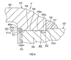
- an insertion hole 49 through which the shaft 35 is passed is formed in the coupling portion 48 that couples base ends of the arms 46, 47 of the first universal joint yoke 43, to which the shaft 35 is coupled, so as to form a U-shape.
- An end face 48a of the coupling portion 48 forms an annular recess 50 that faces the joint cross 45.
- the insertion hole 49 has a first opening 51 that opens at a bottom 50a of the annular recess 50 and a second opening 52 that opens on the opposite side of the coupling portion 48 from the first opening 51.
- the shaft 35 has a distal end portion 53 that has passed through the insertion hole 49 and that protrudes from a peripheral edge 51a of the first opening 51, and an outward protrusion 54 serving as a stopper.
- the outward protrusion 54 extends from the distal end portion 53 outward in the radial direction, and faces the peripheral edge 51a of the first opening 51 across a gap AS (see FIG. 4 ) in the axial direction X1.
- the shaft 35 has an insertion portion 55 that adjoins the distal end portion 53 and that is arranged in the insertion hole 49, and a fixed portion 57 that adjoins the insertion portion 55 and that is fixed to a peripheral edge 52a of the second opening 52 via a welded portion 56.
- the distal end portion 53 of the shaft 35 is housed in an inner space of the annular recess 50 and does not protrude from the end face 48a of the coupling portion 48. This prevents the distal end portion 53 from coming into contact with the universal joint yoke 44, thereby preventing the axis crossing angle of the universal joint 6 from being limited.
- the outward protrusion 54 is not in contact with the peripheral edge 51a of the first opening 51, and is not in contact with an inner periphery of the annular recess 50. Therefore, a stress applied to the universal joint yoke 43 is reduced.
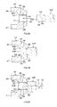
- Engaging protrusions 58 are formed on one of an inner periphery 49a of the first universal joint yoke 43, which defines the insertion hole 49, and an outer periphery 55a of the insertion portion 55. As illustrated in FIG. 5 , in the present embodiment, the engaging protrusions 58 are formed on the outer periphery 55a of the insertion portion 55. Engaged recesses 59 are formed in the other one of the inner periphery 49a of the first universal joint yoke 43, which defines the insertion hole 49, and the outer periphery 55a of the insertion portion 55. As illustrated in FIG.
- the engaged recesses 59 are formed in the inner periphery 49a of the universal joint yoke 43, which defines the insertion hole 49.
- a pair of engaging portions 58a, 58b is formed by a pair of outer faces of each engaging protrusion 58, which are located on the opposite sides of the engaging protrusion 58 in the rotational direction, and a pair of engaged portions 59a, 59b is formed by a pair of inner wall faces of each engaged recess 59.
- the engaging portion 58a of the shaft 35 is engageable with a corresponding one of the engaged portions 59a, with a rotation permitting gap S1 in a first rotational direction Y1.
- the rotation permitting gap S1 is used to adjust the phase between the shaft 35 and the first universal joint yoke 43.
- the engaging portion 58b of the shaft 35 is engageable with a corresponding one of the engaged portions 59b, with a rotation permitting gap S2 in a first rotational direction Y2.
- the rotation permitting gap S2 is used to adjust the phase between the shaft 35 and the first universal joint yoke 43.
- FIG. 7A illustrates a state where the rotation permitting gap S1 that permits the shaft 35 to rotate in the first rotational direction Y1 becomes zero and the engaging portion 58a is engaged with the engaged portion 59a.
- FIG. 7B illustrates a state where the rotation permitting gap S2 that permits the shaft 35 to rotate in the second rotational direction Y2 becomes zero and the engaging portion 58b is engaged with the engaged portion 59b.
- the phase adjustment range achieved by the rotation permitting gaps S1, S2 is set to a range equal to or larger than 5° and equal to or smaller than 30° (5° ⁇ ⁇ ⁇ 30°), where ⁇ is a relative rotation angle between the shaft 35 and the first universal joint yoke 43.
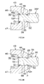
- FIG. 8A the insertion portion 55 of a shaft workpiece 35P in which the engaging portions 58a, 58b are formed (not illustrated in FIG. 8A , see FIG. 6 ) is inserted into the insertion hole 49 through the second opening 52 of the insertion hole 49 of the universal joint yoke 43 in which the engaged portions 59a, 59b are formed (not illustrated in FIG. 8A , see FIG. 6 ).
- FIG. 8B the distal end portion 53 of the shaft workpiece 35P is protruded from the peripheral edge 51a of the first opening 51 of the insertion hole 49.
- the universal joint yoke 43 is rotated in the first rotational direction Y1 or the second rotational direction Y2 with respect to the shaft workpiece 35P.
- the phase of the shaft workpiece 35P with respect to the universal joint yoke 43 is adjusted by adjusting the rotation permitting gaps S1, S2 between the engaging portions 58a, 58b and the engaged portions 59a, 59b.
- a working such as rolling riveting is performed on a distal end portion 53P of the shaft workpiece 35P to form the outward protrusion 54 that protrudes from the distal end portion 53P outward in the radial direction.
- the outward protrusion 54 thus formed faces the peripheral edge 51a of the first opening 51 across the gap AS in the axial direction X1 (see FIG. 4 ).
- a portion of the shaft workpiece 35P, which is close to the peripheral edge 52a of the second opening 52 of the insertion hole 49, is fixed to the peripheral edge 52a of the second opening 52 by welding to form the fixed portion 57. In this way, the coupling structure P is obtained.
- the engaging portions 58a, 58b formed on the outer periphery 55a of the insertion portion 55 of the shaft 35 and the engaged portions 59a, 59b formed in the inner periphery 49a of the first universal joint yoke 43, which defines the insertion hole 49, are engageable with each other in the rotational directions with the rotation permitting gaps S1, S2 used for phase adjustment.
- the phase of the shaft 35 with respect to the first universal joint yoke 43 steplessly within the phase adjustment range defined by the rotation permitting gaps S1, S2. Accordingly, a lot of design variations regarding the phase can be realized with the use of the shaft 35 and the universal joint yoke 43, which are common parts. As a result, the production cost can be reduced by a mass production effect.
- the phase adjustment range is set to a range equal to or larger than 5°, whereby the driver is allowed to reliably recognize occurrence of the failure.
- the phase adjustment range is set to a range equal to or larger than 5° and equal to or smaller than 30°, a sufficient number of design variations regarding the phase can be realized, and it is possible to prevent generation of excessively large backlash during transmission of torque when a failure has occurred, thereby allowing appropriate steering that is an appropriate torque transmission operation.
- the phase is adjusted by rotating the universal joint yoke 43 and the shaft workpiece 35P relative to each other, and then the outward protrusion 54 is formed in the distal end portion 53P of the shaft workpiece 35P.
- the shaft workpiece 35P is fixed to the peripheral edge 52a of the second opening 52 by welding to form the fixed portion 57, whereby the structure P for coupling the shaft to the universal joint yoke is obtained.
- the phase is adjusted before the outward protrusion 54 serving as a stopper is formed in the distal end portion 53P of the shaft workpiece 35P.
- the coupling structure P thus obtained, it is possible to produce the same effects as those of the above-described coupling structure P.
- the invention is not limited to the above-described embodiment.
- the first opening 51 of the insertion hole 49 opens at the bottom 50a of the annular recess 50 formed in the end face 48a of the coupling portion 48.
- the invention is not limited to this configuration.
- the annular recess 50 may be omitted, and the first opening 51 may open at the end face 48a of the coupling portion 48.
- the engaging protrusions 58 each having a pair of the engaging portions 58a, 58b is formed on the outer periphery 55a of the insertion portion 55 of the shaft 35, and the engaged recesses 59 each having a pair of the engaged portions 59a, 59b is formed in the inner periphery 49a of the universal joint yoke 43, which defines the insertion hole 49.
- the invention is not limited to this configuration.
- engaged recesses 59 each having a pair of engaged portions 59a, 59b may be formed in the outer periphery 55a of the insertion portion 55 of the shaft 35, and engaging protrusions 58 each having a pair of engaging portions 58a, 58b may be formed on the inner periphery 49a of the universal joint yoke 43, which defines the insertion hole 49.
Landscapes
- Engineering & Computer Science (AREA)
- General Engineering & Computer Science (AREA)
- Mechanical Engineering (AREA)
- Chemical & Material Sciences (AREA)
- Combustion & Propulsion (AREA)
- Transportation (AREA)
- Steering Controls (AREA)
Applications Claiming Priority (1)
| Application Number | Priority Date | Filing Date | Title |
|---|---|---|---|
| JP2012258943A JP2014105773A (ja) | 2012-11-27 | 2012-11-27 | シャフトと自在継手ヨークの結合構造及び結合方法並びにインターミディエイトシャフト |
Publications (2)
| Publication Number | Publication Date |
|---|---|
| EP2735752A2 true EP2735752A2 (de) | 2014-05-28 |
| EP2735752A3 EP2735752A3 (de) | 2015-07-15 |
Family
ID=49674180
Family Applications (1)
| Application Number | Title | Priority Date | Filing Date |
|---|---|---|---|
| EP13193804.5A Withdrawn EP2735752A3 (de) | 2012-11-27 | 2013-11-21 | Kopplungsstruktur zur Kopplung einer Welle an eine universelle Kreuzgabel, Kopplungsverfahren zur Kopplung einer Welle an eine universelle Kreuzgabel und Zwischenwelle |
Country Status (4)
| Country | Link |
|---|---|
| US (1) | US9469332B2 (de) |
| EP (1) | EP2735752A3 (de) |
| JP (1) | JP2014105773A (de) |
| CN (1) | CN103836084A (de) |
Cited By (2)
| Publication number | Priority date | Publication date | Assignee | Title |
|---|---|---|---|---|
| EP3202639A1 (de) * | 2016-02-01 | 2017-08-09 | Jtekt Corporation | Lenksystem |
| EP3650723A4 (de) * | 2017-08-04 | 2020-05-27 | NSK Ltd. | Wellenkupplungsstruktur und teleskopwelle |
Families Citing this family (18)
| Publication number | Priority date | Publication date | Assignee | Title |
|---|---|---|---|---|
| DE102011121481A1 (de) * | 2011-12-16 | 2013-06-20 | Audi Ag | Schaltvorrichtung mit einem Drehfreilauf für die Schaltwelle und Kraftfahrzeug-Getriebe mit einer solchen Schaltvorrichtung |
| US9663133B2 (en) * | 2013-02-15 | 2017-05-30 | Steering Solutions Ip Holding Corporation | Intermediate shaft for steering column with bearing and lock sleeve |
| US9616914B2 (en) | 2014-02-20 | 2017-04-11 | Steering Solutions Ip Holding Corporation | Telescope and adaptive energy absorption system |
| US9663136B2 (en) * | 2014-02-20 | 2017-05-30 | Steering Solutions Ip Holding Corporation | Steering column having anti-rotation feature |
| US9499190B2 (en) | 2014-03-06 | 2016-11-22 | Steering Solutions Ip Holding Corporation | Adjustable steering column assembly having self-de-lashing power-rake mechanism |
| US9545942B2 (en) | 2014-07-16 | 2017-01-17 | Steering Solutions Ip Holding Corporation | Assembly detection means |
| US9522694B2 (en) | 2015-02-27 | 2016-12-20 | Steering Solutions Ip Holding Corporation | Radial telescope bushing for steering column |
| US9803700B2 (en) * | 2016-03-09 | 2017-10-31 | Magna Powertrain, Inc. | Clutch ring gear assembly and method of construction thereof |
| CN106224361A (zh) * | 2016-08-29 | 2016-12-14 | 万向钱潮传动轴有限公司 | 一种可在任意相位状态下安装的传动轴 |
| US10464590B2 (en) | 2016-10-07 | 2019-11-05 | Steering Solutions Ip Holding Corporation | Steering column energy absorbing system |
| US20180118259A1 (en) * | 2016-10-31 | 2018-05-03 | Steering Solutions Ip Holding Corporation | Torsion bar for a steering system assembly |
| CN106523540A (zh) * | 2016-12-21 | 2017-03-22 | 上海萨菱机电设备有限公司 | 主轴旋转联轴器 |
| KR101836126B1 (ko) * | 2017-03-06 | 2018-03-12 | (주)성진포머 | 샤프트요크 제조용 성형금형 및 이에 의해 제조된 샤프트요크 |
| US10526003B2 (en) | 2017-09-28 | 2020-01-07 | Steering Solutions Ip Holding Corporation | Shroud guidance mechanism for steering column |
| US10464592B2 (en) | 2017-10-30 | 2019-11-05 | Steering Solutions Ip Holding Corporation | Steering column motion control assembly |
| JP2020011623A (ja) * | 2018-07-19 | 2020-01-23 | 日立オートモティブシステムズ株式会社 | ステアリング装置 |
| CN111331905A (zh) * | 2020-03-06 | 2020-06-26 | 新乡市先恒机械设备有限公司 | 一种带有十字接头的斜置传送机 |
| US12181004B2 (en) | 2021-06-22 | 2024-12-31 | JSI Equipment Solutions LLC | Flexible coupling for a drive train |
Citations (1)
| Publication number | Priority date | Publication date | Assignee | Title |
|---|---|---|---|---|
| JP2012112509A (ja) | 2010-11-29 | 2012-06-14 | Nsk Ltd | シャフトとヨークの結合方法及び結合構造 |
Family Cites Families (23)
| Publication number | Priority date | Publication date | Assignee | Title |
|---|---|---|---|---|
| US2394405A (en) * | 1944-02-24 | 1946-02-05 | Gen Motors Corp | Two stage propeller shaft |
| US4402626A (en) * | 1981-02-09 | 1983-09-06 | Recker Florian B | Torque transmitting coupling |
| JPH03204417A (ja) * | 1989-12-28 | 1991-09-06 | Toyota Motor Corp | スプライン軸の嵌合構造およびその製作法 |
| US5522669A (en) * | 1993-12-13 | 1996-06-04 | Recker; Florian B. | Torque transmitting coupling device |
| US5657545A (en) * | 1995-12-05 | 1997-08-19 | Dana Corporation | Fixture for identifying phase angle relationships in a steering shaft assembly |
| JP3917707B2 (ja) | 1997-03-27 | 2007-05-23 | 株式会社松井製作所 | 駆動軸の製造方法 |
| US5827122A (en) * | 1997-06-06 | 1998-10-27 | Neapco, Inc. | Radial free motion driveline |
| JP3367424B2 (ja) * | 1998-05-28 | 2003-01-14 | トヨタ自動車株式会社 | 動力伝達装置の振動特性測定方法 |
| JP2001214943A (ja) * | 2000-02-02 | 2001-08-10 | Sumitomo Heavy Ind Ltd | 動力伝達構造 |
| IT1314484B1 (it) * | 2000-02-15 | 2002-12-18 | Edi Bondioli | Trasmissione meccanica a cannocchiale con adattamento angolare per ilmontaggio |
| US7314416B2 (en) * | 2001-08-30 | 2008-01-01 | Gkn Walterscheid Gmbh | Drive shaft coupling |
| FR2830912B1 (fr) * | 2001-10-15 | 2003-12-19 | Nacam | Dispositif d'accouplement en rotation de deux arbres telescopiques |
| JP4249596B2 (ja) * | 2003-10-30 | 2009-04-02 | 澤藤電機株式会社 | スタータ |
| JP4016956B2 (ja) * | 2004-03-04 | 2007-12-05 | トヨタ自動車株式会社 | エンジンの可変動弁機構及びその制御装置 |
| JP2006038058A (ja) * | 2004-07-26 | 2006-02-09 | Nsk Ltd | 軸部材と相手部材との結合部 |
| JP2006097485A (ja) * | 2004-09-28 | 2006-04-13 | Musashi Seimitsu Ind Co Ltd | カムシャフト及びその組み立て方法 |
| JP4692817B2 (ja) * | 2005-08-03 | 2011-06-01 | 株式会社ジェイテクト | 駆動軸の製造方法 |
| US7905297B2 (en) * | 2007-09-25 | 2011-03-15 | Deere & Company | Automatic connection for mid-mounted implement |
| JP2009196386A (ja) * | 2008-02-19 | 2009-09-03 | Nsk Ltd | ステアリング装置 |
| JP5508243B2 (ja) * | 2010-12-07 | 2014-05-28 | 株式会社ジェイテクト | 操舵伝達軸と自在継手のヨークの結合構造及び車両用操舵装置 |
| JP5516533B2 (ja) * | 2011-08-10 | 2014-06-11 | 日本精工株式会社 | ステアリング装置用トルク伝達装置 |
| JP5708464B2 (ja) * | 2011-12-09 | 2015-04-30 | トヨタ自動車株式会社 | 連結構造 |
| JP2013185686A (ja) * | 2012-03-09 | 2013-09-19 | Jtekt Corp | スプライン伸縮軸 |
-
2012
- 2012-11-27 JP JP2012258943A patent/JP2014105773A/ja active Pending
-
2013
- 2013-11-14 CN CN201310566448.5A patent/CN103836084A/zh active Pending
- 2013-11-19 US US14/084,101 patent/US9469332B2/en not_active Expired - Fee Related
- 2013-11-21 EP EP13193804.5A patent/EP2735752A3/de not_active Withdrawn
Patent Citations (1)
| Publication number | Priority date | Publication date | Assignee | Title |
|---|---|---|---|---|
| JP2012112509A (ja) | 2010-11-29 | 2012-06-14 | Nsk Ltd | シャフトとヨークの結合方法及び結合構造 |
Cited By (4)
| Publication number | Priority date | Publication date | Assignee | Title |
|---|---|---|---|---|
| EP3202639A1 (de) * | 2016-02-01 | 2017-08-09 | Jtekt Corporation | Lenksystem |
| CN107054442A (zh) * | 2016-02-01 | 2017-08-18 | 株式会社捷太格特 | 转向装置 |
| EP3650723A4 (de) * | 2017-08-04 | 2020-05-27 | NSK Ltd. | Wellenkupplungsstruktur und teleskopwelle |
| US11022179B2 (en) | 2017-08-04 | 2021-06-01 | Nsk Ltd. | Shaft coupling structure and telescopic shaft |
Also Published As
| Publication number | Publication date |
|---|---|
| US20140147197A1 (en) | 2014-05-29 |
| US9469332B2 (en) | 2016-10-18 |
| CN103836084A (zh) | 2014-06-04 |
| JP2014105773A (ja) | 2014-06-09 |
| EP2735752A3 (de) | 2015-07-15 |
Similar Documents
| Publication | Publication Date | Title |
|---|---|---|
| US9469332B2 (en) | Coupling structure for coupling shaft to universal joint yoke, coupling method for coupling shaft to universal joint yoke, and intermediate shaft | |
| EP2463176B1 (de) | Gabelkopf- und Antriebswelle Gelenkverbindung und Fahrzeuglenkung | |
| EP3085603B1 (de) | Kerbverzahnte teleskopwelle zur lenkung und lenkvorrichtung | |
| EP2409894A1 (de) | Fahrzeuglenkungssystem | |
| US6006854A (en) | Electric power steering apparatus | |
| EP3009331B1 (de) | Elektrisch unterstützte servolenkvorrichtung | |
| KR20170027170A (ko) | 자동차의 조향컬럼 | |
| JP5176349B2 (ja) | ステアリング装置 | |
| JP2012096681A (ja) | シャフトと自在継手のヨークの結合構造および電動パワーステアリング装置 | |
| JP2009292306A (ja) | 衝撃吸収操舵装置 | |
| EP3081458B1 (de) | Elektrische servolenkvorrichtung und verfahren zur montage | |
| JP6011858B2 (ja) | 伸縮シャフトおよびステアリング装置 | |
| KR102350046B1 (ko) | 자동차의 조향 컬럼 | |
| JP5293695B2 (ja) | ステアリング装置のための自在継手とシャフトの結合構造 | |
| CN107107944B (zh) | 转向角可变式转向装置 | |
| JP2015168306A5 (de) | ||
| JP5332723B2 (ja) | インターミディエイトシャフト | |
| JP2016088491A (ja) | 電動パワーステアリング装置用のステアリングコラム構造 | |
| JP5445660B2 (ja) | ステアリング装置 | |
| JP2010194547A (ja) | 自在継手およびその加工方法 | |
| JP2016215734A (ja) | 電動パワーステアリング装置 | |
| JP2025068994A (ja) | クランプ装置、該クランプ装置と回転軸との結合構造、及びステアリング装置 | |
| KR20170087657A (ko) | 자동차의 조향컬럼 | |
| JP2025064736A (ja) | クランプ装置、該クランプ装置の製造方法、及びステアリング装置 | |
| JP2023177531A (ja) | ステアリング装置用中間シャフト |
Legal Events
| Date | Code | Title | Description |
|---|---|---|---|
| PUAI | Public reference made under article 153(3) epc to a published international application that has entered the european phase |
Free format text: ORIGINAL CODE: 0009012 |
|
| 17P | Request for examination filed |
Effective date: 20131121 |
|
| AK | Designated contracting states |
Kind code of ref document: A2 Designated state(s): AL AT BE BG CH CY CZ DE DK EE ES FI FR GB GR HR HU IE IS IT LI LT LU LV MC MK MT NL NO PL PT RO RS SE SI SK SM TR |
|
| AX | Request for extension of the european patent |
Extension state: BA ME |
|
| PUAL | Search report despatched |
Free format text: ORIGINAL CODE: 0009013 |
|
| AK | Designated contracting states |
Kind code of ref document: A3 Designated state(s): AL AT BE BG CH CY CZ DE DK EE ES FI FR GB GR HR HU IE IS IT LI LT LU LV MC MK MT NL NO PL PT RO RS SE SI SK SM TR |
|
| AX | Request for extension of the european patent |
Extension state: BA ME |
|
| RIC1 | Information provided on ipc code assigned before grant |
Ipc: F16D 1/072 20060101ALI20150605BHEP Ipc: F16D 1/068 20060101ALI20150605BHEP Ipc: F16D 1/12 20060101ALI20150605BHEP Ipc: B62D 1/20 20060101ALI20150605BHEP Ipc: F16D 1/06 20060101AFI20150605BHEP Ipc: F16D 3/38 20060101ALI20150605BHEP |
|
| R17P | Request for examination filed (corrected) |
Effective date: 20160105 |
|
| RBV | Designated contracting states (corrected) |
Designated state(s): AL AT BE BG CH CY CZ DE DK EE ES FI FR GB GR HR HU IE IS IT LI LT LU LV MC MK MT NL NO PL PT RO RS SE SI SK SM TR |
|
| STAA | Information on the status of an ep patent application or granted ep patent |
Free format text: STATUS: THE APPLICATION HAS BEEN WITHDRAWN |
|
| 18W | Application withdrawn |
Effective date: 20161031 |