EP2735829A2 - Erregersystem von entfernbaren Komponenten mit elektrisch-elektronischen Vorrichtungen und elektrisches Ansteuerungsverfahren für in entfernbaren Komponenten angeordnete Vorrichtungen - Google Patents
Erregersystem von entfernbaren Komponenten mit elektrisch-elektronischen Vorrichtungen und elektrisches Ansteuerungsverfahren für in entfernbaren Komponenten angeordnete Vorrichtungen Download PDFInfo
- Publication number
- EP2735829A2 EP2735829A2 EP13193039.8A EP13193039A EP2735829A2 EP 2735829 A2 EP2735829 A2 EP 2735829A2 EP 13193039 A EP13193039 A EP 13193039A EP 2735829 A2 EP2735829 A2 EP 2735829A2
- Authority
- EP
- European Patent Office
- Prior art keywords
- electric
- equipment
- conductive
- energizing system
- removable components
- Prior art date
- Legal status (The legal status is an assumption and is not a legal conclusion. Google has not performed a legal analysis and makes no representation as to the accuracy of the status listed.)
- Withdrawn
Links
- 238000000034 method Methods 0.000 title claims description 3
- 239000004020 conductor Substances 0.000 claims description 11
- 230000008878 coupling Effects 0.000 claims description 4
- 238000010168 coupling process Methods 0.000 claims description 4
- 238000005859 coupling reaction Methods 0.000 claims description 4
- 230000005611 electricity Effects 0.000 abstract description 2
- 238000005286 illumination Methods 0.000 description 6
- 239000002184 metal Substances 0.000 description 5
- 238000010276 construction Methods 0.000 description 2
- 238000006467 substitution reaction Methods 0.000 description 2
- 235000013305 food Nutrition 0.000 description 1
- 230000001771 impaired effect Effects 0.000 description 1
- 238000009434 installation Methods 0.000 description 1
- 239000000463 material Substances 0.000 description 1
- 238000012986 modification Methods 0.000 description 1
- 230000004048 modification Effects 0.000 description 1
Images

Classifications
-
- F—MECHANICAL ENGINEERING; LIGHTING; HEATING; WEAPONS; BLASTING
- F25—REFRIGERATION OR COOLING; COMBINED HEATING AND REFRIGERATION SYSTEMS; HEAT PUMP SYSTEMS; MANUFACTURE OR STORAGE OF ICE; LIQUEFACTION SOLIDIFICATION OF GASES
- F25D—REFRIGERATORS; COLD ROOMS; ICE-BOXES; COOLING OR FREEZING APPARATUS NOT OTHERWISE PROVIDED FOR
- F25D27/00—Lighting arrangements
- F25D27/005—Lighting arrangements combined with control means
-
- F—MECHANICAL ENGINEERING; LIGHTING; HEATING; WEAPONS; BLASTING
- F25—REFRIGERATION OR COOLING; COMBINED HEATING AND REFRIGERATION SYSTEMS; HEAT PUMP SYSTEMS; MANUFACTURE OR STORAGE OF ICE; LIQUEFACTION SOLIDIFICATION OF GASES
- F25D—REFRIGERATORS; COLD ROOMS; ICE-BOXES; COOLING OR FREEZING APPARATUS NOT OTHERWISE PROVIDED FOR
- F25D25/00—Charging, supporting, and discharging the articles to be cooled
- F25D25/02—Charging, supporting, and discharging the articles to be cooled by shelves
-
- F—MECHANICAL ENGINEERING; LIGHTING; HEATING; WEAPONS; BLASTING
- F25—REFRIGERATION OR COOLING; COMBINED HEATING AND REFRIGERATION SYSTEMS; HEAT PUMP SYSTEMS; MANUFACTURE OR STORAGE OF ICE; LIQUEFACTION SOLIDIFICATION OF GASES
- F25D—REFRIGERATORS; COLD ROOMS; ICE-BOXES; COOLING OR FREEZING APPARATUS NOT OTHERWISE PROVIDED FOR
- F25D27/00—Lighting arrangements
-
- F—MECHANICAL ENGINEERING; LIGHTING; HEATING; WEAPONS; BLASTING
- F25—REFRIGERATION OR COOLING; COMBINED HEATING AND REFRIGERATION SYSTEMS; HEAT PUMP SYSTEMS; MANUFACTURE OR STORAGE OF ICE; LIQUEFACTION SOLIDIFICATION OF GASES
- F25D—REFRIGERATORS; COLD ROOMS; ICE-BOXES; COOLING OR FREEZING APPARATUS NOT OTHERWISE PROVIDED FOR
- F25D29/00—Arrangement or mounting of control or safety devices
-
- F—MECHANICAL ENGINEERING; LIGHTING; HEATING; WEAPONS; BLASTING
- F25—REFRIGERATION OR COOLING; COMBINED HEATING AND REFRIGERATION SYSTEMS; HEAT PUMP SYSTEMS; MANUFACTURE OR STORAGE OF ICE; LIQUEFACTION SOLIDIFICATION OF GASES
- F25D—REFRIGERATORS; COLD ROOMS; ICE-BOXES; COOLING OR FREEZING APPARATUS NOT OTHERWISE PROVIDED FOR
- F25D2325/00—Charging, supporting or discharging the articles to be cooled, not provided for in other groups of this subclass
- F25D2325/022—Shelves made of glass or ceramic
-
- F—MECHANICAL ENGINEERING; LIGHTING; HEATING; WEAPONS; BLASTING
- F25—REFRIGERATION OR COOLING; COMBINED HEATING AND REFRIGERATION SYSTEMS; HEAT PUMP SYSTEMS; MANUFACTURE OR STORAGE OF ICE; LIQUEFACTION SOLIDIFICATION OF GASES
- F25D—REFRIGERATORS; COLD ROOMS; ICE-BOXES; COOLING OR FREEZING APPARATUS NOT OTHERWISE PROVIDED FOR
- F25D2400/00—General features of, or devices for refrigerators, cold rooms, ice-boxes, or for cooling or freezing apparatus not covered by any other subclass
- F25D2400/40—Refrigerating devices characterised by electrical wiring
Definitions
- the present invention pertains to the field of parts and accessories for household appliances and refers to removable components of equipments comprising wireless powered electronic devices. More specifically, the present invention refers to removable shelves comprising illuminating means, wherein their electric power supply is carried out without the need of wires for interconnecting the power source ant the element to be supplied.
- removable-type elements such as shelves
- removable shelves are commonly used in a number of equipments, wherein a typical use of such removable elements is in refrigerators.
- US Patent 5,287,252 refers to a movable shelf provided with a front illumination system, however, to assemble it, wires and other elements (e.g. a conductive strip and connectors) are required to bring into contact the shelf with a power source, which is usually disposed at the equipment housing itself.
- wires and other elements e.g. a conductive strip and connectors
- WO 2011/019589 and US Patent 6,813,896 disclose removable illuminated shelves which, however, require the use of two side power buses to supply electricity to the lamps and in addition they use connectors to obtain power from the power bus, which renders such construction and mounting of equipments complex and expensive.
- one of the objects of the present invention is to provide power supply to all wireless electronic devices of removable components, preferably shelves.
- Another object of the present invention is to provide removable components for household appliances and equipments in general which can be electrically connected to a power source with no need to use further electric components, such as, for example, connectors.
- Yet another object of the present invention is to provide a removable component which can simultaneously use its own structure as electric connector and aesthetic finishing.
- the present invention comprises means for allowing wireless electric connection between at least an element removably secured to at least a support structure of equipment and structure 3 of the equipment.
- said element comprises: a transparent flat plate having a perimeter covered with a frame provided with, under one ou more of the surfaces thereof, an electric or electronic driving system, wherein side elements having ends provided with engaging/securing means for coupling with the conductive regions contained in the support structures of the refrigerator housing are disposed together the side portions of the frame.
- said frame is constituted by an electric conductive material at least in the interconnection region between the electric driving device and conductive regions contained in the support structures.
- the electric driving devices are light emitting devices (LEDs).
- the power source is a low voltage power source.
- Another object of the present invention refers an electric driving method for devices disposed at removable components for equipments in general comprising the step of contacting at least a portion of an electric conductive surface of a removable component comprising at least an electronic component with at least a portion of electric conductive surface of a fixed structure, wherein said structure fixed structure is connected to an electric power source.
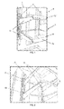
- the energizing system of the present invention basically comprises a element 1 removably secured to a support structure 2 coupled with or disposed in housing 3 of equipment 4 which as formerly said is preferably a refrigerator.
- said element 1 is preferably defined by a preferably transparent flat plate 11 having a perimeter covered with a frame 12 provided with, under or more of its surfaces, an electric or electronic driving system, such as, for example, a LEDs plate (shown in Fig. 2 ).
- said frame 12 should be made of a high electrical conductivity material (e.g. metal) such that the own structure of element 1 can be used as a conductor so that the use of electric wires and cables are not needed.
- a high electrical conductivity material e.g. metal
- the side surfaces of element 1 preferably cooperate with side elements 13 also provided, even partially, with a region of conductive material interconnecting the area contacting with the electric driving system 5 with the end of said side element 13, which comprises any engaging and/or securing means 14 which allow for safe coupling thereof to spans 21 contained in the refrigerator housing support structure 2 of the refrigerator housing for removably holding said element 1.
- Such spans as well as the engaging and/or securing means of element 1 can be better seen from Fig. 4 .
- the two side elements 13 of said elements 1 will be preferably coupled to corresponding support structures; however, only one of such structures is needed to energize the element 1 such that costs for mounting the equipment are reduced.
- fixed structure 2 of the present invention comprises a conductive region 21 cooperative with conductive material 6 of element 1, wherein said conductive regions 21 are connected to positive and negative poles of an electric power source 7, preferably a low voltage source.
- the device as depicted in the figures comprised means for permitting wireless electric connection between at least one element 1 removably secured to at least a support structure 2 of housing 3 of an equipment.
- the electric power source can be a low voltage DC power source or another similar equipment which preferably is hidden inside the apparatus housing or in its outer region (not shown) and connected so as to energize the metal portion of element 1 whenever the refrigerator door opens and whenever said element 1 is duly coupled to the support structure 2 of housing 3.
- the energizing system of the present invention consists of removable shelves 1 with LEDs disposed on the front regions thereof to provide better illumination conditions inside the refrigerated compartment. Said set of LEDs is electrically connected to the metal portion of the shelf.
- a low voltage DC source 7 is energizing at least one metal fixed structure 2 such that LEDs of the shelf turn on when the doors of equipment 1, in this case a refrigerator, opens and the shelf is positioned in the support structure 2, and LEDs turn off when any of the doors of equipment 1 closes or if the shelf 1 is removed from said structure 2.
- the contact between said metal structure 2 and the shelf support 1 is what feeds LEDs 5.
Landscapes
- Engineering & Computer Science (AREA)
- Chemical & Material Sciences (AREA)
- Combustion & Propulsion (AREA)
- Physics & Mathematics (AREA)
- Mechanical Engineering (AREA)
- Thermal Sciences (AREA)
- General Engineering & Computer Science (AREA)
- Arrangement Of Elements, Cooling, Sealing, Or The Like Of Lighting Devices (AREA)
- Devices That Are Associated With Refrigeration Equipment (AREA)
Applications Claiming Priority (1)
| Application Number | Priority Date | Filing Date | Title |
|---|---|---|---|
| BR102012029702A BR102012029702A2 (pt) | 2012-11-22 | 2012-11-22 | sistema de energização de componentes removíveis para equipamentos em geral, e processo de acionamento elétrico para dispositivos dispostos em componentes removíveis para equipamentos em geral |
Publications (2)
| Publication Number | Publication Date |
|---|---|
| EP2735829A2 true EP2735829A2 (de) | 2014-05-28 |
| EP2735829A3 EP2735829A3 (de) | 2016-09-07 |
Family
ID=49585303
Family Applications (1)
| Application Number | Title | Priority Date | Filing Date |
|---|---|---|---|
| EP13193039.8A Withdrawn EP2735829A3 (de) | 2012-11-22 | 2013-11-15 | Erregersystem von entfernbaren Komponenten mit elektrisch-elektronischen Vorrichtungen und elektrisches Ansteuerungsverfahren für in entfernbaren Komponenten angeordnete Vorrichtungen |
Country Status (3)
| Country | Link |
|---|---|
| US (1) | US20140140040A1 (de) |
| EP (1) | EP2735829A3 (de) |
| BR (1) | BR102012029702A2 (de) |
Families Citing this family (10)
| Publication number | Priority date | Publication date | Assignee | Title |
|---|---|---|---|---|
| US9212848B2 (en) | 2013-03-15 | 2015-12-15 | Whirlpool Corporation | Apparatus, system, and method for storage in a refrigerated appliance |
| KR20230020552A (ko) | 2013-06-20 | 2023-02-10 | 젬트론 코포레이션 | 가전기기 조명용 조명기구 |
| KR101667728B1 (ko) | 2014-11-10 | 2016-10-19 | 엘지전자 주식회사 | 냉장고 |
| KR101695694B1 (ko) * | 2014-12-09 | 2017-01-12 | 엘지전자 주식회사 | 조명가능한 선반을 구비한 냉장고 |
| US9581383B2 (en) | 2015-05-18 | 2017-02-28 | Haier Us Appliance Solutions, Inc. | Refrigerator appliances |
| CN109690214A (zh) * | 2016-09-14 | 2019-04-26 | 开利公司 | 用于制冷柜的柔性轨系统 |
| CN113405300A (zh) * | 2021-07-14 | 2021-09-17 | 青岛海尔电冰箱有限公司 | 具有搁物架的冷藏装置 |
| CN113405301A (zh) * | 2021-07-14 | 2021-09-17 | 青岛海尔电冰箱有限公司 | 用于冷藏装置的搁物架 |
| KR20240090183A (ko) * | 2021-10-15 | 2024-06-21 | 에스에스더블유 어드밴스드 테크놀로지, 엘엘씨 | 조명 선반 조립체 |
| WO2025116357A1 (ko) * | 2023-11-30 | 2025-06-05 | 엘지전자 주식회사 | 냉장고 |
Citations (6)
| Publication number | Priority date | Publication date | Assignee | Title |
|---|---|---|---|---|
| US5287252A (en) | 1993-01-14 | 1994-02-15 | Sub-Zero Freezer Company, Inc. | Adjustable illuminated refrigerator shelf |
| US5297836A (en) | 1991-07-03 | 1994-03-29 | Jaguar Cars Limited | Motor car chasis structure |
| US6813896B1 (en) | 2003-07-30 | 2004-11-09 | Whirlpool Corporation | Power bus for removable refrigerator shelves |
| US7107779B2 (en) | 2002-01-22 | 2006-09-19 | Miele & Cie. Kg. | Refrigerating appliance, especially a refrigerator |
| WO2009014885A1 (en) | 2007-07-20 | 2009-01-29 | Electrolux Home Products, Inc. | Refrigerator shelf led lighting |
| WO2011019589A1 (en) | 2009-08-14 | 2011-02-17 | Illinois Tool Works Inc. | Inductively powered lighting assembly |
Family Cites Families (1)
| Publication number | Priority date | Publication date | Assignee | Title |
|---|---|---|---|---|
| WO2009148611A1 (en) * | 2008-06-04 | 2009-12-10 | Ssw Holding Company, Inc. | Shelf with led assembly |
-
2012
- 2012-11-22 BR BR102012029702A patent/BR102012029702A2/pt not_active Application Discontinuation
-
2013
- 2013-11-15 EP EP13193039.8A patent/EP2735829A3/de not_active Withdrawn
- 2013-11-21 US US14/086,443 patent/US20140140040A1/en not_active Abandoned
Patent Citations (6)
| Publication number | Priority date | Publication date | Assignee | Title |
|---|---|---|---|---|
| US5297836A (en) | 1991-07-03 | 1994-03-29 | Jaguar Cars Limited | Motor car chasis structure |
| US5287252A (en) | 1993-01-14 | 1994-02-15 | Sub-Zero Freezer Company, Inc. | Adjustable illuminated refrigerator shelf |
| US7107779B2 (en) | 2002-01-22 | 2006-09-19 | Miele & Cie. Kg. | Refrigerating appliance, especially a refrigerator |
| US6813896B1 (en) | 2003-07-30 | 2004-11-09 | Whirlpool Corporation | Power bus for removable refrigerator shelves |
| WO2009014885A1 (en) | 2007-07-20 | 2009-01-29 | Electrolux Home Products, Inc. | Refrigerator shelf led lighting |
| WO2011019589A1 (en) | 2009-08-14 | 2011-02-17 | Illinois Tool Works Inc. | Inductively powered lighting assembly |
Also Published As
| Publication number | Publication date |
|---|---|
| US20140140040A1 (en) | 2014-05-22 |
| EP2735829A3 (de) | 2016-09-07 |
| BR102012029702A2 (pt) | 2016-01-26 |
Similar Documents
| Publication | Publication Date | Title |
|---|---|---|
| EP2735829A2 (de) | Erregersystem von entfernbaren Komponenten mit elektrisch-elektronischen Vorrichtungen und elektrisches Ansteuerungsverfahren für in entfernbaren Komponenten angeordnete Vorrichtungen | |
| US9502832B1 (en) | Duplex receptacle having a plurality of LEDs to illuminate the sockets | |
| US9732921B2 (en) | Multiple functions wall cover plate has built-in USB and light means | |
| US9644834B2 (en) | Electrified medicine cabinet | |
| EP2765379A3 (de) | Stromversorgungen für beleuchtete Regale in einem Kühlschrank | |
| EP3032200B1 (de) | Kühlschrank mit regalbeleuchtung | |
| KR102120708B1 (ko) | 전력 전달 버스 시스템 | |
| MX392729B (es) | Receptáculo eléctrico para mobiliario | |
| EP2765376A3 (de) | Konfigurierbare Stromversorgungsschaltung für beleuchtete Regale in einem Kühlschrank | |
| US20160316939A1 (en) | Rack system having an electrical supply | |
| US20080043456A1 (en) | Shelf light bracket connector system | |
| US20170198888A1 (en) | Switchgear cabinet luminaire comprising illuminants on the basis of light emitting diodes | |
| US9357858B2 (en) | Low voltage plug and play display system | |
| MXPA98008067A (es) | Exhibidor de portalamparas de iluminacion. | |
| US20050117339A1 (en) | Illuminating light string arrangement | |
| JP2012040334A (ja) | 陳列棚の照明装置 | |
| WO2007126449A3 (en) | Lighting assembly having an integrated solid-state light emitting device | |
| JP2018527696A (ja) | 家具システムの3次元支持管構造の管に挿入するための負荷モジュール | |
| US5716128A (en) | Power takeoff and lighting unit for fluorescent fixture | |
| US5893627A (en) | Automatic low voltage lighting system for cabinets and closets | |
| JP3193890U (ja) | 陳列棚 | |
| JP6096917B2 (ja) | 照明付きの引き出し、照明装置及び集電器 | |
| US20140334154A1 (en) | Device for lighting a subjacent area | |
| JP6467755B2 (ja) | Led照明器具 | |
| JP3195062U (ja) | 照明器具 |
Legal Events
| Date | Code | Title | Description |
|---|---|---|---|
| PUAI | Public reference made under article 153(3) epc to a published international application that has entered the european phase |
Free format text: ORIGINAL CODE: 0009012 |
|
| 17P | Request for examination filed |
Effective date: 20131115 |
|
| AK | Designated contracting states |
Kind code of ref document: A2 Designated state(s): AL AT BE BG CH CY CZ DE DK EE ES FI FR GB GR HR HU IE IS IT LI LT LU LV MC MK MT NL NO PL PT RO RS SE SI SK SM TR |
|
| AX | Request for extension of the european patent |
Extension state: BA ME |
|
| PUAL | Search report despatched |
Free format text: ORIGINAL CODE: 0009013 |
|
| AK | Designated contracting states |
Kind code of ref document: A3 Designated state(s): AL AT BE BG CH CY CZ DE DK EE ES FI FR GB GR HR HU IE IS IT LI LT LU LV MC MK MT NL NO PL PT RO RS SE SI SK SM TR |
|
| AX | Request for extension of the european patent |
Extension state: BA ME |
|
| RIC1 | Information provided on ipc code assigned before grant |
Ipc: F25D 27/00 20060101AFI20160804BHEP Ipc: F25D 25/02 20060101ALI20160804BHEP Ipc: F25D 29/00 20060101ALI20160804BHEP |
|
| STAA | Information on the status of an ep patent application or granted ep patent |
Free format text: STATUS: THE APPLICATION IS DEEMED TO BE WITHDRAWN |
|
| 18D | Application deemed to be withdrawn |
Effective date: 20170308 |