EP2735860B1 - Optofluidische Vorrichtung - Google Patents
Optofluidische Vorrichtung Download PDFInfo
- Publication number
- EP2735860B1 EP2735860B1 EP13193828.4A EP13193828A EP2735860B1 EP 2735860 B1 EP2735860 B1 EP 2735860B1 EP 13193828 A EP13193828 A EP 13193828A EP 2735860 B1 EP2735860 B1 EP 2735860B1
- Authority
- EP
- European Patent Office
- Prior art keywords
- optical fiber
- capillary
- light guiding
- optofluidic device
- fiber
- Prior art date
- Legal status (The legal status is an assumption and is not a legal conclusion. Google has not performed a legal analysis and makes no representation as to the accuracy of the status listed.)
- Active
Links
Images

Classifications
-
- B—PERFORMING OPERATIONS; TRANSPORTING
- B01—PHYSICAL OR CHEMICAL PROCESSES OR APPARATUS IN GENERAL
- B01L—CHEMICAL OR PHYSICAL LABORATORY APPARATUS FOR GENERAL USE
- B01L3/00—Containers or dishes for laboratory use, e.g. laboratory glassware; Droppers
- B01L3/50—Containers for the purpose of retaining a material to be analysed, e.g. test tubes
- B01L3/502—Containers for the purpose of retaining a material to be analysed, e.g. test tubes with fluid transport, e.g. in multi-compartment structures
- B01L3/5027—Containers for the purpose of retaining a material to be analysed, e.g. test tubes with fluid transport, e.g. in multi-compartment structures by integrated microfluidic structures, i.e. dimensions of channels and chambers are such that surface tension forces are important, e.g. lab-on-a-chip
- B01L3/502715—Containers for the purpose of retaining a material to be analysed, e.g. test tubes with fluid transport, e.g. in multi-compartment structures by integrated microfluidic structures, i.e. dimensions of channels and chambers are such that surface tension forces are important, e.g. lab-on-a-chip characterised by interfacing components, e.g. fluidic, electrical, optical or mechanical interfaces
-
- G—PHYSICS
- G01—MEASURING; TESTING
- G01N—INVESTIGATING OR ANALYSING MATERIALS BY DETERMINING THEIR CHEMICAL OR PHYSICAL PROPERTIES
- G01N21/00—Investigating or analysing materials by the use of optical means, i.e. using sub-millimetre waves, infrared, visible or ultraviolet light
- G01N21/01—Arrangements or apparatus for facilitating the optical investigation
- G01N21/03—Cuvette constructions
- G01N21/05—Flow-through cuvettes
-
- G—PHYSICS
- G01—MEASURING; TESTING
- G01N—INVESTIGATING OR ANALYSING MATERIALS BY DETERMINING THEIR CHEMICAL OR PHYSICAL PROPERTIES
- G01N21/00—Investigating or analysing materials by the use of optical means, i.e. using sub-millimetre waves, infrared, visible or ultraviolet light
- G01N21/17—Systems in which incident light is modified in accordance with the properties of the material investigated
- G01N21/47—Scattering, i.e. diffuse reflection
- G01N21/49—Scattering, i.e. diffuse reflection within a body or fluid
- G01N21/51—Scattering, i.e. diffuse reflection within a body or fluid inside a container, e.g. in an ampoule
-
- B—PERFORMING OPERATIONS; TRANSPORTING
- B01—PHYSICAL OR CHEMICAL PROCESSES OR APPARATUS IN GENERAL
- B01L—CHEMICAL OR PHYSICAL LABORATORY APPARATUS FOR GENERAL USE
- B01L2200/00—Solutions for specific problems relating to chemical or physical laboratory apparatus
- B01L2200/12—Specific details about manufacturing devices
-
- B—PERFORMING OPERATIONS; TRANSPORTING
- B01—PHYSICAL OR CHEMICAL PROCESSES OR APPARATUS IN GENERAL
- B01L—CHEMICAL OR PHYSICAL LABORATORY APPARATUS FOR GENERAL USE
- B01L2300/00—Additional constructional details
- B01L2300/06—Auxiliary integrated devices, integrated components
- B01L2300/0627—Sensor or part of a sensor is integrated
- B01L2300/0654—Lenses; Optical fibres
-
- B—PERFORMING OPERATIONS; TRANSPORTING
- B01—PHYSICAL OR CHEMICAL PROCESSES OR APPARATUS IN GENERAL
- B01L—CHEMICAL OR PHYSICAL LABORATORY APPARATUS FOR GENERAL USE
- B01L2300/00—Additional constructional details
- B01L2300/08—Geometry, shape and general structure
- B01L2300/0832—Geometry, shape and general structure cylindrical, tube shaped
- B01L2300/0838—Capillaries
-
- B—PERFORMING OPERATIONS; TRANSPORTING
- B01—PHYSICAL OR CHEMICAL PROCESSES OR APPARATUS IN GENERAL
- B01L—CHEMICAL OR PHYSICAL LABORATORY APPARATUS FOR GENERAL USE
- B01L2300/00—Additional constructional details
- B01L2300/08—Geometry, shape and general structure
- B01L2300/0861—Configuration of multiple channels and/or chambers in a single devices
- B01L2300/0877—Flow chambers
-
- G—PHYSICS
- G01—MEASURING; TESTING
- G01N—INVESTIGATING OR ANALYSING MATERIALS BY DETERMINING THEIR CHEMICAL OR PHYSICAL PROPERTIES
- G01N21/00—Investigating or analysing materials by the use of optical means, i.e. using sub-millimetre waves, infrared, visible or ultraviolet light
- G01N21/01—Arrangements or apparatus for facilitating the optical investigation
- G01N21/03—Cuvette constructions
- G01N2021/0346—Capillary cells; Microcells
-
- G—PHYSICS
- G01—MEASURING; TESTING
- G01N—INVESTIGATING OR ANALYSING MATERIALS BY DETERMINING THEIR CHEMICAL OR PHYSICAL PROPERTIES
- G01N21/00—Investigating or analysing materials by the use of optical means, i.e. using sub-millimetre waves, infrared, visible or ultraviolet light
- G01N21/01—Arrangements or apparatus for facilitating the optical investigation
- G01N21/03—Cuvette constructions
- G01N2021/0364—Cuvette constructions flexible, compressible
-
- G—PHYSICS
- G01—MEASURING; TESTING
- G01N—INVESTIGATING OR ANALYSING MATERIALS BY DETERMINING THEIR CHEMICAL OR PHYSICAL PROPERTIES
- G01N21/00—Investigating or analysing materials by the use of optical means, i.e. using sub-millimetre waves, infrared, visible or ultraviolet light
- G01N21/01—Arrangements or apparatus for facilitating the optical investigation
- G01N21/03—Cuvette constructions
- G01N21/05—Flow-through cuvettes
- G01N2021/052—Tubular type; cavity type; multireflective
-
- G—PHYSICS
- G01—MEASURING; TESTING
- G01N—INVESTIGATING OR ANALYSING MATERIALS BY DETERMINING THEIR CHEMICAL OR PHYSICAL PROPERTIES
- G01N21/00—Investigating or analysing materials by the use of optical means, i.e. using sub-millimetre waves, infrared, visible or ultraviolet light
- G01N21/62—Systems in which the material investigated is excited whereby it emits light or causes a change in wavelength of the incident light
- G01N21/63—Systems in which the material investigated is excited whereby it emits light or causes a change in wavelength of the incident light optically excited
- G01N21/64—Fluorescence; Phosphorescence
- G01N21/645—Specially adapted constructive features of fluorimeters
- G01N2021/6482—Sample cells, cuvettes
-
- G—PHYSICS
- G01—MEASURING; TESTING
- G01N—INVESTIGATING OR ANALYSING MATERIALS BY DETERMINING THEIR CHEMICAL OR PHYSICAL PROPERTIES
- G01N2201/00—Features of devices classified in G01N21/00
- G01N2201/08—Optical fibres; light guides
Definitions
- the present invention relates to an optofluidic device. More particularly, the present invention relates to an optofluidic device for coupling light into a fluid and to a method for manufacturing such an optofluidic device.
- Optofluidics refers to the field of science where light and fluid interacts to allow for analysis, separation and for exploiting the optical properties of a medium.
- a typical device configuration in optofluidics involves optical waveguides and capillaries for fluid flow. The optical excitation of the fluid material by laser light is generally done transversally, i.e. with the light impinging upon the capillary from the side. In many cases, it would be desirable to excite an extended region of the fluid (for example up to 30 cm long region), but this is difficult in a configuration with transverse illumination.
- One natural step would then be to attempt to illuminate the liquid under examination in a longitudinal configuration, i.e. where the illuminating light travels along the capillary.
- a longitudinal configuration i.e. where the illuminating light travels along the capillary.
- one serious limitation associated with longitudinal, or axial, illumination of a liquid is the interface of the liquid. At any open end in the capillary, the liquid forms a meniscus causing a lens effect.
- the exposure of the liquid under examination to ambient conditions such as air is often undesirable for stability reasons, and for chemical and/or biological reasons.
- EP1653216 addresses the abovementioned problem by disclosing a microfluidic device where light from an optical fiber is coupled longitudinally into a liquid in an all-spliced arrangement without meniscus formation, thereby containing the liquid in a protected environment.
- light propagating in the core of the fiber can be used for exciting and analyzing the substances in the solution.
- the liquid is inserted by polishing the side of the fiber to open holes therein, and by letting the liquid into longitudinal channels of the optical fiber through the opened holes without blocking the light flow.
- WO2004/090510 discloses a device for evanescently coupling light into a liquid, wherein the light comprises an optical fiber having a light guiding core and a plurality of capillaries arranged in said fiber adjacent to and in parallel with said light guiding core of said optical fiber, wherein the capillaries can be filled by the liquid for spectroscopic analysis.
- an object of the present invention to provide an improved optofluidic device which provides efficient light coupling while being both more robust and easier to manufacture.
- an optofluidic device according to claim 1.
- optically coupled should be understood such that the two fibers are arranged so that light may propagate from the light guiding core of the first optical fiber to the light guiding core of the second optical fiber.
- the optical coupling may either be direct through a physical connection between the two fibers or indirect through an intermediate transparent material allowing propagation of light between the fibers. It should be understood that guidance in the reverse direction is also allowed, i.e., light may be collected by the second fiber through luminescence or scattering and delivered back to the first fiber, for example for analysis.
- An optical fiber should in the present context be understood as similar to a conventional optical fiber, i.e. having a solid light guiding core and a protective cladding, unless explicitly stated otherwise.
- a conventional optical fiber can for example be found in high speed communication applications.
- the external source from which light is provided can be any light source arranged external to the optofluidic device.
- the light source may for example be a laser, a light emitting diode, a supercontinuum light source or ambient light.
- Light from the light source is coupled into the light guiding core of the first optical fiber which in turn guides the light to the second optical fiber.
- a capillary here refers to a tubular structure capable of guiding a fluid.
- a capillary may for example be an optical fiber having one or more longitudinal channels made within the fiber, or a capillary may be a tube made from a flexible material such as rubber or a flexible polymer. It should be noted that the physical phenomena of capillary action is not required for the optofluidic device to function and that capillary merely describes a tubular channel having a relatively small inner diameter.
- Optical fiber refers to any type of optical fiber capable of guiding light known to the person skilled in the art.
- the optical fiber may for example be made from different types of glass or plastic materials.
- the fiber fluid channels refer to longitudinally extending fluid channels arranged essentially in parallel with the light guiding core.
- a fluid may refer to both a liquid and a gas, as the optofluidic device is equally well suited for analysis of both liquids and gases.
- the present invention is based on the realization that an improved optofluidic device where light and fluid can propagate simultaneously, which is more robust and compact, may be achieved through an arrangement where fluid and light are separately provided to an end surface of an optical fiber comprising a solid light guiding core and a fiber fluid channel.
- an efficient light coupling between the first optical fiber and the second optical fiber can be achieved while at the same time providing fluid to the second optical fiber without using openings in the sidewall of an optical fiber.
- the diameter of the optical fibers and capillaries ranges between approximately 100-1000 ⁇ m and the fiber fluid channels may have diameters from a few ⁇ m up to hundreds of ⁇ m. Such sizes are suitable for analysis of small volume samples using light, for instance, the identification of cells, bacteria and proteins.
- Another example application of optofluidics is where light is coupled into a hollow-core that allows for optical propagation, and there interacts with a gas contained in the hollow core over long distances for efficient wavelength conversion.
- the light guiding core may also be a hollow core.
- pump light of a shorter wavelength is coupled into a hollow core that allows for light propagation and interaction with a wavelength converting luminescent liquid, or with a polymerized material inserted as a liquid and subsequently cured, such as to provide a laser emitting light at a longer wavelength.
- the device described herein may advantageously be used in reverse order, where light and fluid are coupled from the second optical fiber and are separated into light guided in the first optical fiber and fluid in the capillary.
- At least a portion of the second optical fiber may advantageously be arranged within the capillary.
- the second optical fiber By arranging the second optical fiber at least partially within the capillary such that the end portion of the second optical fiber optically coupled to the first optical fiber extends a predetermined distance into the capillary, an overlap is provided between the second optical fiber and the capillary which may simplify manufacturing of the device and which also reduces the risk of fluid leakage at the interface between the second optical fiber and the capillary.
- a second capillary of a smaller diameter than the first capillary may be inserted into the capillary fluid channel, and the outer capillary may be collapsed around the inner smaller diameter capillary to facilitate an external fluidic connection to the capillary fluid channel, and subsequently to the fiber fluid channel.
- At least one of the first optical fiber and the second optical fiber may comprise a plurality of light guiding cores.
- An optical fiber comprising a plurality of cores may for example be used if it is desirable to provide light of different wavelengths by optically coupling separate cores of the first optical fibers to corresponding cores of the second optical fiber. Light of different wavelengths may then be provided to each of the cores of the first optical fiber. Thereby, a fluid may be made to interact with light of different wavelengths without the use of different optofluidic devices or without needing to switch the input device.
- the plurality of cores can be arranged in various ways known by the person skilled in the art.
- two cores in the second optical fiber could be arranged coaxially, one for the delivery of light to the fluid and the other one for the collection of light back to the detector. By separating the two optical paths, it becomes easier to prevent cross-talk between the delivered light to the sample and retrieved light from the sample.
- At least one of the core of the first optical fiber and the core of the second optical fiber may advantageously be an imaging core.
- an imaging core of a fiber can be used to provide an image of an object while simultaneously providing a fluid to the location which is observed through the fiber fluid channel.
- a fiber having an imaging core can for example be used in an endoscope for medical imaging.
- An optical fiber having an imaging core may also be referred to as an imaging fiber.
- the first optical fiber is be spliced to said second optical fiber, thereby forming a physical connection between the two fibers.
- the two fibers may be mechanically spliced together or heated so that the fibers are fused. Accordingly, the arrangement allows for coupling of the optical fibers through splicing, which can be made with low loss and at low cost.
- the optofluidic device may further comprise a seal arranged between the first optical fiber and a sidewall of the capillary to prevent leakage of fluid from the capillary.
- the seal may for example comprise a ceramic, a glass-based material, a resin, a glue or the like providing a seal between the sidewall of the capillary and the first optical fiber. Sealing may for example be achieved by providing a material which is cured to form a ceramic or glass seal. Preferably, the sealing material may be bio-compatible.
- the optical fibers may be either single-mode fibers or multi-mode fibers.
- a multimode optical fiber may be used to reduce coherence effects (speckle) and to allow for a larger light collection cross-section compared with a single mode fiber.
- the diameter of the first optical fiber may advantageously be smaller than the diameter of the second optical fiber.
- light may be coupled from the light guiding core of the first optical fiber to the light guiding core of the second optical fiber while fluid can flow from the capillary into longitudinal fluid channels in the second optical fibers having openings at the end surface of the second optical fiber.
- the dead volume is small, allowing for efficient fluid pumping through and from the fiber fluid channel.
- the optofluidic device may preferably comprise a protective housing enclosing a portion of said optofluidic device comprising said opening.
- a housing is advantageously arranged surrounding the opening to provide mechanical protection to avoid that the first optical fiber breaks at the opening of the capillary. Such mechanical protection may be particularly important when the first optical fiber is thinner than a conventional fiber thereby making it more fragile.
- the housing may be embodied as a conventional splice protector sleeve, or as a similar tubular structure providing sufficient mechanical protection.
- the protective housing may advantageously comprise a heat-shrink material.
- a heat-shrink material may for example comprise a thermoplastic material such as a polymer which is configured to shrink when exposed to heat.
- the interface between the first optical fiber and the second optical fiber may be arranged adjacent to the opening where the first optical fiber passes through the capillary wall.
- the forming of the optical connection can be performed outside of the capillary, thereby making it possible to use conventional methods for connecting optical fibers such as splicing.
- the step of forming an opening in a sidewall of said tubular capillary may advantageously comprise laser ablation polishing, etching or ion milling of said fiber.
- the method may further comprise the step of providing a protective housing enclosing the optofluidic device in a region surrounding said opening.
- a capillary of a smaller diameter than the inner diameter of the capillary fluid channel may be inserted into the capillary fluid channel and the outer capillary may be collapsed around the inner smaller diameter capillary.
- Fig. 1 illustrates an optofluidic device 100 comprising a first optical fiber 102 having a light guiding core 104, a capillary 106 having a capillary fluid channel 108, a second optical fiber 110 having a light guiding core 112 and four fiber fluid channels 114 in parallel with the light guiding core 112.
- the second optical fiber 110 is arranged within the capillary fluid channel 108 to allow direct fluid communication between the capillary fluid channel 108 and each of the fiber fluid channels 114.
- the first optical fiber 102 extends through an opening 116 in a sidewall of the capillary 106 and is further optically coupled to the second optical fiber 110 so that light may be guided from an external source into the light guiding core 112 of the second optical fiber 110.
- the opening 116 where the first optical fiber 102 enters into the capillary 106 is sealed 118 with a resin or a similar material to ensure that fluid does not leak from the capillary fluid channel 108 through the opening 116.
- the first optical fiber 102 is a standard silica telecom fiber, with an original diameter of 125 ⁇ m, having been etched down to a diameter of 50 ⁇ m and with an 8 ⁇ m germanium doped core.
- the second optical fiber 110 is equal to the first optical fiber 102 except that it has a diameter of 125 ⁇ m, and with four longitudinal tubular fluid channels 114 formed within.
- the tubular fluid channels 114 extend longitudinally in the fiber adjacent to (i.e. not coinciding) and in parallel with the light guiding core 112. The tubular fluid channels 114 are thus arranged at a distance from the light guiding core 112.
- the capillary 106 is a silica fiber capillary with an inner diameter of 127 ⁇ m and outer diameter of 250 ⁇ m.
- Fig. 2a illustrates a portion of the optofluidic device where it can be seen that the first optical fiber 102 is spliced to the second optical fiber 110 so that the light guiding cores 104, 112 are in contact and aligned in order to allow light being guided from an external source into the core 104 of the first optical fiber 102 and further into the core 112 of the second optical fiber 110 such that optical losses are kept at a minimum.
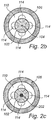
- Fig. 2b it is illustrated how the difference in diameter of the first optical fiber 102 and the second optical fiber 110 along with the arrangement of the fiber fluid channels 114 allows for a fluid to flow from the capillary fluid channel 108 into the fiber fluid channels 114 when the first optical fiber 102 is coupled to the second optical fiber 110.
- Fig. 2c schematically illustrates an optofluidic device where optical fibers comprise multiple light guiding cores 202.
- the diameter of the optical fiber may for example vary between 50 ⁇ m and 3 mm and the diameter of the light guiding core may be between 5 and 50 ⁇ m for a single mode core and between 50 and 500 ⁇ m for a multimode core.
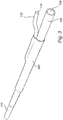
- Fig. 3 illustrates the optofluidic device 100 enclosed in a protective housing 302, i.e. a protective sleeve, in the form of a standard splice protector.
- the protective sleeve 302 comprises a heat shrinking plastic material so that the optofluidic device 100 is securely enclosed after heat treatment of the sleeve 302.
- the protective sleeve may further comprise a straight rigid rod (not shown), such as a steel rod, for mechanical support to ensure that the optofluidic device is not damaged from bending of the protective sleeve.
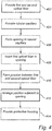
- Fig. 4 is a flow-chart outlining the general manufacturing steps of the method for manufacturing the optofluidic device 100 described above.
- a first and a second optical fiber 102, 110 is provided. At least a portion of the first optical fiber 102 has been thinned down from the standard diameter of 125 ⁇ m to 50 ⁇ m by etching in hydrofluoric acid (HF) and the second optical fiber 110 comprises four tubular fiber fluid channels 114.
- the etched first optical fiber 102 is cleaved with a standard fiber cleaver to provide a smooth end surface of the fiber.
- a tubular capillary 106 is provided 404 and a an opening 116 in the sidewall of the capillary 106 is formed 406 by polishing from the side of the capillary 106 using a rotating drum with an attached sandpaper to create an opening 116 having a length of approximately 1 mm and a width of approximately 60 ⁇ m.
- the first optical fiber 102 is then inserted 408 through the polished opening 116 into the capillary 106.
- the first optical fiber is pulled through the opening so that its end extend out of the capillary in order to facilitate fusion splicing 410 of the first optical fiber 102 to the second optical fiber 110.
- the joined first and second fibers 102, 110 are pulled back inside the capillary 106 so that the junction between the fibers is located close to the opening 116 of the capillary 106 as illustrated in Fig. 1 , or at least within the capillary.
- the opening 116 in the capillary 106 and the opening at the end of the capillary where the second optical fiber 110 exits the capillary fluid channel 108 are sealed with an adhesive or a resin so that fluid cannot leak from the capillary 106.
- the sealing material may preferably be biocompatible.
- a smaller diameter capillary (not shown) may be arranged within the capillary fluid channel 108 to facilitate external coupling of a fluid into the optofluidic device 100.
- step 414 the fiber arrangement is placed inside a standard splice protector 302 comprising a heat-shrink material, and the splice protector is heat treated to shrink around the optofluidic device 100.
Landscapes
- Chemical & Material Sciences (AREA)
- Health & Medical Sciences (AREA)
- General Health & Medical Sciences (AREA)
- Analytical Chemistry (AREA)
- Life Sciences & Earth Sciences (AREA)
- Biochemistry (AREA)
- Physics & Mathematics (AREA)
- General Physics & Mathematics (AREA)
- Immunology (AREA)
- Pathology (AREA)
- Dispersion Chemistry (AREA)
- Hematology (AREA)
- Clinical Laboratory Science (AREA)
- Chemical Kinetics & Catalysis (AREA)
- Optical Couplings Of Light Guides (AREA)
Claims (14)
- Optofluidische Vorrichtung (100), zum Einkoppeln von Licht in eine Flüssigkeit, umfassend:einen ersten Lichtwellenleiter (102), wobei der erste Lichtwellenleiter einen festen Lichtleitkern (104) hat;eine Kapillare (106), wobei die Kapillare einen Kapillarfluidkanal (108) hat;einen zweiten Lichtwellenleiter (110), wobei der zweite Lichtwellenleiter einen festen Lichtleitkern (112) und mindestens einen Faserfluidkanal (114) hat, der neben und parallel zu dem Lichtleitkern des zweiten Lichtwellenleiters angeordnet ist;wobei der Kapillarfluidkanal (108) in direkter Fluidverbindung mit dem mindestens einen Faserfluidkanal (114) angeordnet ist; undwobei sich der erste Lichtwellenleiter (102) durch eine Öffnung (116) in einer Seitenwand der Kapillare (106) erstreckt und optisch mit dem zweiten Lichtwellenleiter(110) gekoppelt ist, um Licht von einer externen Lichtquelle in den Lichtleitkern (112) des zweiten Lichtwellenleiters (110) zu leiten,wobei der erste Lichtwellenleiter (102) mit dem zweiten Lichtwellenleiter (110) gespleißt ist.
- Optofluidische Vorrichtung (100) nach Anspruch 1, wobei mindestens ein Teil des zweiten Lichtwellenleiters (112) innerhalb der Kapillare (106) angeordnet ist.
- Optofluidische Vorrichtung (100) nach Anspruch 1 oder 2, wobei mindestens einer des ersten Lichtwellenleiters (102) und des zweiten Lichtwellenleiters (110) mehrere Lichtleitkerne (202) umfasst.
- Optofluidische Vorrichtung (100) nach einem der vorhergehenden Ansprüche, wobei mindestens einer des Lichtleitkerns (104) des ersten Lichtwellenleiters (102) und des Lichtleitkerns (112) des zweiten Lichtwellenleiters (110) ein Bildgebungskern ist.
- Optofluidische Vorrichtung (100) nach einem der vorhergehenden Ansprüche, ferner umfassend eine Dichtung (118), die zwischen dem ersten Lichtwellenleiter (102) und einer Seitenwand der Kapillare (106) angeordnet ist, um ein Austreten von Flüssigkeit aus der Kapillare zu verhindern.
- Optofluidische Vorrichtung (100) nach Anspruch 6, wobei die Dichtung (118) ein Harz oder einen Klebstoff umfasst.
- Optofluidische Vorrichtung (100) nach einem der vorhergehenden Ansprüche, wobei mindestens einer des ersten Lichtwellenleiters (102) und des zweiten Lichtwellenleiters (110) ein Singlemode- Lichtwellenleiter ist.
- Optofluidische Vorrichtung (100) nach einem der vorhergehenden Ansprüche, wobei mindestens einer des ersten Lichtwellenleiters (102) und des zweiten Lichtwellenleiters (110) ein Multimode- Lichtwellenleiters ist.
- Optofluidische Vorrichtung (100) nach einem der vorhergehenden Ansprüche, wobei der Durchmesser des ersten Lichtwellenleiters (102) kleiner ist als der Durchmesser des zweiten Lichtwellenleiters (110).
- Optofluidische Vorrichtung (100) nach einem der vorhergehenden Ansprüche, ferner umfassend ein Schutzgehäuse (302), das einen Teil der optofluidische Vorrichtung (100) das die Öffnung (116) umschließt, umfasst.
- Optofluidische Vorrichtung (100) nach Anspruch 10, wobei das Schutzgehäuse (302) ein Wärmeschrumpfmaterial umfasst.
- Verfahren zur Herstellung einer optofluidischen Vorrichtung (100) zum Einkoppeln von Licht in eine Flüssigkeit, umfassend die Schritte:Bereitstellen (402) eines ersten Lichtwellenleiters (102), wobei der Lichtwellenleiter einen ersten festen Lichtleitkern (104) umfasst, und einen zweiten Lichtwellenleiter (110), der einen zweiten festen Lichtleitkern umfasst (112) und mindestens einen Längsfaserfluidkanal (114), der neben und parallel zu dem festen Lichtleitkern (112) angeordnet ist;Bereitstellen (404) einer röhrenförmigen Kapillare (106), wobei die Kapillare einem Kapillarfluidkanal (108) hat;Bilden (406) einer Öffnung (116) in einer Seitenwand der röhrenförmigen Kapillare (106);Einführen (408) des ersten Lichtwellenleiters (102) in die röhrenförmige Kapillare (106) durch die Öffnung (116);Bilden (410) einer Grenzfläche zwischen dem ersten Lichtwellenleiter (102) und dem zweiten Lichtwellenleiter (110), so dass eine optische Verbindung zwischen dem ersten Lichtleitkern (104) und dem zweiten Lichtleitkern (112) gebildet wird, wobei die Grenzfläche durch Spleißen des ersten Lichtwellenleiters (102) mit dem zweiten Lichtwellenleiter (110) gebildet wird; undAnordnen (412) des ersten Lichtwellenleiters (102) und des zweiten Lichtwellenleiters (110) innerhalb der Kapillare (106), so dass sich die Grenzfläche innerhalb der Kapillare (106) befindet.
- Verfahren nach Anspruch 12, wobei der Schritt des Bildens einer Öffnung in einer Seitenwand der röhrenförmigen Kapillare (106) das Polieren durch Laserablation, Ätzen oder lonenfräsen der röhrenförmigen Kapillare umfasst.
- Verfahren nach Anspruch 12 oder 13, ferner umfassend den Schritt des Bereitstellens (414) eines Schutzgehäuses (302),wobei das Schutzgehäuse die optofluidische Vorrichtung (100) in einem Bereich, der die Öffnung (116) umgibt, umschließt.
Priority Applications (1)
| Application Number | Priority Date | Filing Date | Title |
|---|---|---|---|
| EP13193828.4A EP2735860B1 (de) | 2012-11-21 | 2013-11-21 | Optofluidische Vorrichtung |
Applications Claiming Priority (2)
| Application Number | Priority Date | Filing Date | Title |
|---|---|---|---|
| EP12193614 | 2012-11-21 | ||
| EP13193828.4A EP2735860B1 (de) | 2012-11-21 | 2013-11-21 | Optofluidische Vorrichtung |
Publications (2)
| Publication Number | Publication Date |
|---|---|
| EP2735860A1 EP2735860A1 (de) | 2014-05-28 |
| EP2735860B1 true EP2735860B1 (de) | 2020-09-30 |
Family
ID=47355818
Family Applications (1)
| Application Number | Title | Priority Date | Filing Date |
|---|---|---|---|
| EP13193828.4A Active EP2735860B1 (de) | 2012-11-21 | 2013-11-21 | Optofluidische Vorrichtung |
Country Status (1)
| Country | Link |
|---|---|
| EP (1) | EP2735860B1 (de) |
Cited By (1)
| Publication number | Priority date | Publication date | Assignee | Title |
|---|---|---|---|---|
| WO2026069266A1 (en) * | 2024-09-30 | 2026-04-02 | Inesc Tec - Instituto De Engenharia De Sistemas E Computadores, Tecnologia E Ciência | Optofluidic device based on a laser-machined capillary |
Families Citing this family (1)
| Publication number | Priority date | Publication date | Assignee | Title |
|---|---|---|---|---|
| CN113376095B (zh) * | 2021-05-08 | 2022-10-18 | 邯郸学院 | 一种信号集成光微流传感器 |
Citations (1)
| Publication number | Priority date | Publication date | Assignee | Title |
|---|---|---|---|---|
| WO2004090510A1 (en) * | 2003-04-14 | 2004-10-21 | Alight Technologies A/S | Optical fibre needle for spectroscopic analysis of liquids |
Family Cites Families (2)
| Publication number | Priority date | Publication date | Assignee | Title |
|---|---|---|---|---|
| US5493629A (en) * | 1994-07-05 | 1996-02-20 | The United States Of America As Represented By The Secretary Of The Air Force | Liquid core heat exchangers for fiber optic sensing and method using same |
| SE0402609L (sv) | 2004-10-26 | 2006-03-21 | Acreo Ab | Mikrofluidikanordning |
-
2013
- 2013-11-21 EP EP13193828.4A patent/EP2735860B1/de active Active
Patent Citations (1)
| Publication number | Priority date | Publication date | Assignee | Title |
|---|---|---|---|---|
| WO2004090510A1 (en) * | 2003-04-14 | 2004-10-21 | Alight Technologies A/S | Optical fibre needle for spectroscopic analysis of liquids |
Cited By (1)
| Publication number | Priority date | Publication date | Assignee | Title |
|---|---|---|---|---|
| WO2026069266A1 (en) * | 2024-09-30 | 2026-04-02 | Inesc Tec - Instituto De Engenharia De Sistemas E Computadores, Tecnologia E Ciência | Optofluidic device based on a laser-machined capillary |
Also Published As
| Publication number | Publication date |
|---|---|
| EP2735860A1 (de) | 2014-05-28 |
Similar Documents
| Publication | Publication Date | Title |
|---|---|---|
| Bellini et al. | Femtosecond laser fabricated monolithic chip for optical trapping and stretching of single cells | |
| Mogensen et al. | Integration of polymer waveguides for optical detection in microfabricated chemical analysis systems | |
| Cai et al. | A new fabrication method for all-PDMS waveguides | |
| Schmidt et al. | Optofluidic waveguides: I. Concepts and implementations | |
| US7693369B2 (en) | Hollow core optical ring resonator sensor, sensing methods, and methods of fabrication | |
| Zhang et al. | Ultra-sensitive chemical and biological analysis via specialty fibers with built-in microstructured optofluidic channels | |
| Warren-Smith et al. | Exposed core microstructured optical fiber Bragg gratings: refractive index sensing | |
| US10078181B2 (en) | Robust fiber cell for atomic and molecular sensing | |
| US20150212279A1 (en) | Optical device having liquid-core optical fibre and method for producing such a device | |
| Sudirman et al. | All-fiber optofluidic component to combine light and fluid | |
| EP1653216B1 (de) | Mikrofluidische Vorrichtung | |
| Lim et al. | Fluorescent liquid-core/air-cladding waveguides towards integrated optofluidic light sources | |
| EP2735860B1 (de) | Optofluidische Vorrichtung | |
| Wang et al. | Microfluidic channels with ultralow-loss waveguide crossings for various chip-integrated photonic sensors | |
| US20100284863A1 (en) | Biosensor cartridge and biosensor mounting system with integral fluid storage and fluid selection mechanisms | |
| Wu et al. | Side-hole microstructured optical fiber integrative twin-microchannels for optofluidic sensing | |
| Odeh et al. | Gradient-index optofluidic waveguide in polydimethylsiloxane | |
| Liu et al. | Development of an integrated direct-contacting optical-fiber microchip with light-emitting diode-induced fluorescence detection | |
| Li et al. | Highly efficient fluorescence detection using a simplified hollow core microstructured optical fiber | |
| JP2008116313A (ja) | 微少量液体測定装置 | |
| Fleger et al. | Microfabricated polymer analysis chip for optical detection | |
| Paiva Jr et al. | Polyimide removal, cleaving, and fusion splicing of cylindrical and square fused silica capillaries for new separation and detection layouts in capillary electrophoresis and chromatography | |
| US20140099703A1 (en) | Capillary Waveguide Cuvette | |
| Cordeiro et al. | Side Access to the Holes of Photonic Crystal Fibers–new sensing possibilities | |
| US10209187B1 (en) | Method for atomic and molecular sensing |
Legal Events
| Date | Code | Title | Description |
|---|---|---|---|
| PUAI | Public reference made under article 153(3) epc to a published international application that has entered the european phase |
Free format text: ORIGINAL CODE: 0009012 |
|
| 17P | Request for examination filed |
Effective date: 20131121 |
|
| AK | Designated contracting states |
Kind code of ref document: A1 Designated state(s): AL AT BE BG CH CY CZ DE DK EE ES FI FR GB GR HR HU IE IS IT LI LT LU LV MC MK MT NL NO PL PT RO RS SE SI SK SM TR |
|
| AX | Request for extension of the european patent |
Extension state: BA ME |
|
| R17P | Request for examination filed (corrected) |
Effective date: 20141127 |
|
| RBV | Designated contracting states (corrected) |
Designated state(s): AL AT BE BG CH CY CZ DE DK EE ES FI FR GB GR HR HU IE IS IT LI LT LU LV MC MK MT NL NO PL PT RO RS SE SI SK SM TR |
|
| GRAP | Despatch of communication of intention to grant a patent |
Free format text: ORIGINAL CODE: EPIDOSNIGR1 |
|
| STAA | Information on the status of an ep patent application or granted ep patent |
Free format text: STATUS: GRANT OF PATENT IS INTENDED |
|
| INTG | Intention to grant announced |
Effective date: 20200324 |
|
| GRAS | Grant fee paid |
Free format text: ORIGINAL CODE: EPIDOSNIGR3 |
|
| GRAA | (expected) grant |
Free format text: ORIGINAL CODE: 0009210 |
|
| STAA | Information on the status of an ep patent application or granted ep patent |
Free format text: STATUS: THE PATENT HAS BEEN GRANTED |
|
| AK | Designated contracting states |
Kind code of ref document: B1 Designated state(s): AL AT BE BG CH CY CZ DE DK EE ES FI FR GB GR HR HU IE IS IT LI LT LU LV MC MK MT NL NO PL PT RO RS SE SI SK SM TR |
|
| RAP1 | Party data changed (applicant data changed or rights of an application transferred) |
Owner name: RISE RESEARCH INSTITUTES OF SWEDEN AB |
|
| REG | Reference to a national code |
Ref country code: GB Ref legal event code: FG4D Ref country code: CH Ref legal event code: EP |
|
| REG | Reference to a national code |
Ref country code: AT Ref legal event code: REF Ref document number: 1319304 Country of ref document: AT Kind code of ref document: T Effective date: 20201015 Ref country code: DE Ref legal event code: R096 Ref document number: 602013072898 Country of ref document: DE |
|
| REG | Reference to a national code |
Ref country code: IE Ref legal event code: FG4D |
|
| PG25 | Lapsed in a contracting state [announced via postgrant information from national office to epo] |
Ref country code: BG Free format text: LAPSE BECAUSE OF FAILURE TO SUBMIT A TRANSLATION OF THE DESCRIPTION OR TO PAY THE FEE WITHIN THE PRESCRIBED TIME-LIMIT Effective date: 20201230 Ref country code: FI Free format text: LAPSE BECAUSE OF FAILURE TO SUBMIT A TRANSLATION OF THE DESCRIPTION OR TO PAY THE FEE WITHIN THE PRESCRIBED TIME-LIMIT Effective date: 20200930 Ref country code: NO Free format text: LAPSE BECAUSE OF FAILURE TO SUBMIT A TRANSLATION OF THE DESCRIPTION OR TO PAY THE FEE WITHIN THE PRESCRIBED TIME-LIMIT Effective date: 20201230 Ref country code: HR Free format text: LAPSE BECAUSE OF FAILURE TO SUBMIT A TRANSLATION OF THE DESCRIPTION OR TO PAY THE FEE WITHIN THE PRESCRIBED TIME-LIMIT Effective date: 20200930 Ref country code: GR Free format text: LAPSE BECAUSE OF FAILURE TO SUBMIT A TRANSLATION OF THE DESCRIPTION OR TO PAY THE FEE WITHIN THE PRESCRIBED TIME-LIMIT Effective date: 20201231 Ref country code: SE Free format text: LAPSE BECAUSE OF FAILURE TO SUBMIT A TRANSLATION OF THE DESCRIPTION OR TO PAY THE FEE WITHIN THE PRESCRIBED TIME-LIMIT Effective date: 20200930 |
|
| REG | Reference to a national code |
Ref country code: AT Ref legal event code: MK05 Ref document number: 1319304 Country of ref document: AT Kind code of ref document: T Effective date: 20200930 |
|
| PG25 | Lapsed in a contracting state [announced via postgrant information from national office to epo] |
Ref country code: RS Free format text: LAPSE BECAUSE OF FAILURE TO SUBMIT A TRANSLATION OF THE DESCRIPTION OR TO PAY THE FEE WITHIN THE PRESCRIBED TIME-LIMIT Effective date: 20200930 Ref country code: LV Free format text: LAPSE BECAUSE OF FAILURE TO SUBMIT A TRANSLATION OF THE DESCRIPTION OR TO PAY THE FEE WITHIN THE PRESCRIBED TIME-LIMIT Effective date: 20200930 |
|
| REG | Reference to a national code |
Ref country code: NL Ref legal event code: MP Effective date: 20200930 |
|
| REG | Reference to a national code |
Ref country code: LT Ref legal event code: MG4D |
|
| PG25 | Lapsed in a contracting state [announced via postgrant information from national office to epo] |
Ref country code: EE Free format text: LAPSE BECAUSE OF FAILURE TO SUBMIT A TRANSLATION OF THE DESCRIPTION OR TO PAY THE FEE WITHIN THE PRESCRIBED TIME-LIMIT Effective date: 20200930 Ref country code: CZ Free format text: LAPSE BECAUSE OF FAILURE TO SUBMIT A TRANSLATION OF THE DESCRIPTION OR TO PAY THE FEE WITHIN THE PRESCRIBED TIME-LIMIT Effective date: 20200930 Ref country code: SM Free format text: LAPSE BECAUSE OF FAILURE TO SUBMIT A TRANSLATION OF THE DESCRIPTION OR TO PAY THE FEE WITHIN THE PRESCRIBED TIME-LIMIT Effective date: 20200930 Ref country code: RO Free format text: LAPSE BECAUSE OF FAILURE TO SUBMIT A TRANSLATION OF THE DESCRIPTION OR TO PAY THE FEE WITHIN THE PRESCRIBED TIME-LIMIT Effective date: 20200930 Ref country code: PT Free format text: LAPSE BECAUSE OF FAILURE TO SUBMIT A TRANSLATION OF THE DESCRIPTION OR TO PAY THE FEE WITHIN THE PRESCRIBED TIME-LIMIT Effective date: 20210201 Ref country code: LT Free format text: LAPSE BECAUSE OF FAILURE TO SUBMIT A TRANSLATION OF THE DESCRIPTION OR TO PAY THE FEE WITHIN THE PRESCRIBED TIME-LIMIT Effective date: 20200930 Ref country code: NL Free format text: LAPSE BECAUSE OF FAILURE TO SUBMIT A TRANSLATION OF THE DESCRIPTION OR TO PAY THE FEE WITHIN THE PRESCRIBED TIME-LIMIT Effective date: 20200930 |
|
| PG25 | Lapsed in a contracting state [announced via postgrant information from national office to epo] |
Ref country code: IS Free format text: LAPSE BECAUSE OF FAILURE TO SUBMIT A TRANSLATION OF THE DESCRIPTION OR TO PAY THE FEE WITHIN THE PRESCRIBED TIME-LIMIT Effective date: 20210130 Ref country code: PL Free format text: LAPSE BECAUSE OF FAILURE TO SUBMIT A TRANSLATION OF THE DESCRIPTION OR TO PAY THE FEE WITHIN THE PRESCRIBED TIME-LIMIT Effective date: 20200930 Ref country code: ES Free format text: LAPSE BECAUSE OF FAILURE TO SUBMIT A TRANSLATION OF THE DESCRIPTION OR TO PAY THE FEE WITHIN THE PRESCRIBED TIME-LIMIT Effective date: 20200930 Ref country code: AL Free format text: LAPSE BECAUSE OF FAILURE TO SUBMIT A TRANSLATION OF THE DESCRIPTION OR TO PAY THE FEE WITHIN THE PRESCRIBED TIME-LIMIT Effective date: 20200930 Ref country code: AT Free format text: LAPSE BECAUSE OF FAILURE TO SUBMIT A TRANSLATION OF THE DESCRIPTION OR TO PAY THE FEE WITHIN THE PRESCRIBED TIME-LIMIT Effective date: 20200930 |
|
| PG25 | Lapsed in a contracting state [announced via postgrant information from national office to epo] |
Ref country code: SK Free format text: LAPSE BECAUSE OF FAILURE TO SUBMIT A TRANSLATION OF THE DESCRIPTION OR TO PAY THE FEE WITHIN THE PRESCRIBED TIME-LIMIT Effective date: 20200930 Ref country code: MC Free format text: LAPSE BECAUSE OF FAILURE TO SUBMIT A TRANSLATION OF THE DESCRIPTION OR TO PAY THE FEE WITHIN THE PRESCRIBED TIME-LIMIT Effective date: 20200930 |
|
| REG | Reference to a national code |
Ref country code: CH Ref legal event code: PL |
|
| REG | Reference to a national code |
Ref country code: DE Ref legal event code: R097 Ref document number: 602013072898 Country of ref document: DE |
|
| PG25 | Lapsed in a contracting state [announced via postgrant information from national office to epo] |
Ref country code: LU Free format text: LAPSE BECAUSE OF NON-PAYMENT OF DUE FEES Effective date: 20201121 |
|
| PLBE | No opposition filed within time limit |
Free format text: ORIGINAL CODE: 0009261 |
|
| STAA | Information on the status of an ep patent application or granted ep patent |
Free format text: STATUS: NO OPPOSITION FILED WITHIN TIME LIMIT |
|
| REG | Reference to a national code |
Ref country code: BE Ref legal event code: MM Effective date: 20201130 |
|
| PG25 | Lapsed in a contracting state [announced via postgrant information from national office to epo] |
Ref country code: CH Free format text: LAPSE BECAUSE OF NON-PAYMENT OF DUE FEES Effective date: 20201130 Ref country code: DK Free format text: LAPSE BECAUSE OF FAILURE TO SUBMIT A TRANSLATION OF THE DESCRIPTION OR TO PAY THE FEE WITHIN THE PRESCRIBED TIME-LIMIT Effective date: 20200930 Ref country code: LI Free format text: LAPSE BECAUSE OF NON-PAYMENT OF DUE FEES Effective date: 20201130 |
|
| 26N | No opposition filed |
Effective date: 20210701 |
|
| PG25 | Lapsed in a contracting state [announced via postgrant information from national office to epo] |
Ref country code: IE Free format text: LAPSE BECAUSE OF NON-PAYMENT OF DUE FEES Effective date: 20201121 Ref country code: IT Free format text: LAPSE BECAUSE OF FAILURE TO SUBMIT A TRANSLATION OF THE DESCRIPTION OR TO PAY THE FEE WITHIN THE PRESCRIBED TIME-LIMIT Effective date: 20200930 |
|
| PG25 | Lapsed in a contracting state [announced via postgrant information from national office to epo] |
Ref country code: SI Free format text: LAPSE BECAUSE OF FAILURE TO SUBMIT A TRANSLATION OF THE DESCRIPTION OR TO PAY THE FEE WITHIN THE PRESCRIBED TIME-LIMIT Effective date: 20200930 |
|
| PG25 | Lapsed in a contracting state [announced via postgrant information from national office to epo] |
Ref country code: IS Free format text: LAPSE BECAUSE OF FAILURE TO SUBMIT A TRANSLATION OF THE DESCRIPTION OR TO PAY THE FEE WITHIN THE PRESCRIBED TIME-LIMIT Effective date: 20210130 Ref country code: TR Free format text: LAPSE BECAUSE OF FAILURE TO SUBMIT A TRANSLATION OF THE DESCRIPTION OR TO PAY THE FEE WITHIN THE PRESCRIBED TIME-LIMIT Effective date: 20200930 Ref country code: MT Free format text: LAPSE BECAUSE OF FAILURE TO SUBMIT A TRANSLATION OF THE DESCRIPTION OR TO PAY THE FEE WITHIN THE PRESCRIBED TIME-LIMIT Effective date: 20200930 Ref country code: CY Free format text: LAPSE BECAUSE OF FAILURE TO SUBMIT A TRANSLATION OF THE DESCRIPTION OR TO PAY THE FEE WITHIN THE PRESCRIBED TIME-LIMIT Effective date: 20200930 |
|
| PG25 | Lapsed in a contracting state [announced via postgrant information from national office to epo] |
Ref country code: MK Free format text: LAPSE BECAUSE OF FAILURE TO SUBMIT A TRANSLATION OF THE DESCRIPTION OR TO PAY THE FEE WITHIN THE PRESCRIBED TIME-LIMIT Effective date: 20200930 |
|
| PG25 | Lapsed in a contracting state [announced via postgrant information from national office to epo] |
Ref country code: BE Free format text: LAPSE BECAUSE OF NON-PAYMENT OF DUE FEES Effective date: 20201130 |
|
| PGFP | Annual fee paid to national office [announced via postgrant information from national office to epo] |
Ref country code: DE Payment date: 20251007 Year of fee payment: 13 |
|
| PGFP | Annual fee paid to national office [announced via postgrant information from national office to epo] |
Ref country code: GB Payment date: 20251016 Year of fee payment: 13 |
|
| PGFP | Annual fee paid to national office [announced via postgrant information from national office to epo] |
Ref country code: FR Payment date: 20251008 Year of fee payment: 13 |