EP2736099A1 - Wiederaufladbare Batterie - Google Patents
Wiederaufladbare Batterie Download PDFInfo
- Publication number
- EP2736099A1 EP2736099A1 EP13170193.0A EP13170193A EP2736099A1 EP 2736099 A1 EP2736099 A1 EP 2736099A1 EP 13170193 A EP13170193 A EP 13170193A EP 2736099 A1 EP2736099 A1 EP 2736099A1
- Authority
- EP
- European Patent Office
- Prior art keywords
- safety device
- electrode
- rechargeable battery
- insulation member
- protruded
- Prior art date
- Legal status (The legal status is an assumption and is not a legal conclusion. Google has not performed a legal analysis and makes no representation as to the accuracy of the status listed.)
- Withdrawn
Links
Images






Classifications
-
- H—ELECTRICITY
- H01—ELECTRIC ELEMENTS
- H01M—PROCESSES OR MEANS, e.g. BATTERIES, FOR THE DIRECT CONVERSION OF CHEMICAL ENERGY INTO ELECTRICAL ENERGY
- H01M10/00—Secondary cells; Manufacture thereof
- H01M10/04—Construction or manufacture in general
- H01M10/0413—Large-sized flat cells or batteries for motive or stationary systems with plate-like electrodes
-
- H—ELECTRICITY
- H01—ELECTRIC ELEMENTS
- H01M—PROCESSES OR MEANS, e.g. BATTERIES, FOR THE DIRECT CONVERSION OF CHEMICAL ENERGY INTO ELECTRICAL ENERGY
- H01M10/00—Secondary cells; Manufacture thereof
- H01M10/42—Methods or arrangements for servicing or maintenance of secondary cells or secondary half-cells
- H01M10/4235—Safety or regulating additives or arrangements in electrodes, separators or electrolyte
-
- H—ELECTRICITY
- H01—ELECTRIC ELEMENTS
- H01M—PROCESSES OR MEANS, e.g. BATTERIES, FOR THE DIRECT CONVERSION OF CHEMICAL ENERGY INTO ELECTRICAL ENERGY
- H01M10/00—Secondary cells; Manufacture thereof
- H01M10/04—Construction or manufacture in general
- H01M10/0431—Cells with wound or folded electrodes
-
- H—ELECTRICITY
- H01—ELECTRIC ELEMENTS
- H01M—PROCESSES OR MEANS, e.g. BATTERIES, FOR THE DIRECT CONVERSION OF CHEMICAL ENERGY INTO ELECTRICAL ENERGY
- H01M10/00—Secondary cells; Manufacture thereof
- H01M10/04—Construction or manufacture in general
- H01M10/0436—Small-sized flat cells or batteries for portable equipment
-
- H—ELECTRICITY
- H01—ELECTRIC ELEMENTS
- H01M—PROCESSES OR MEANS, e.g. BATTERIES, FOR THE DIRECT CONVERSION OF CHEMICAL ENERGY INTO ELECTRICAL ENERGY
- H01M10/00—Secondary cells; Manufacture thereof
- H01M10/42—Methods or arrangements for servicing or maintenance of secondary cells or secondary half-cells
- H01M10/44—Methods for charging or discharging
-
- H—ELECTRICITY
- H01—ELECTRIC ELEMENTS
- H01M—PROCESSES OR MEANS, e.g. BATTERIES, FOR THE DIRECT CONVERSION OF CHEMICAL ENERGY INTO ELECTRICAL ENERGY
- H01M50/00—Constructional details or processes of manufacture of the non-active parts of electrochemical cells other than fuel cells, e.g. hybrid cells
- H01M50/10—Primary casings; Jackets or wrappings
- H01M50/102—Primary casings; Jackets or wrappings characterised by their shape or physical structure
-
- H—ELECTRICITY
- H01—ELECTRIC ELEMENTS
- H01M—PROCESSES OR MEANS, e.g. BATTERIES, FOR THE DIRECT CONVERSION OF CHEMICAL ENERGY INTO ELECTRICAL ENERGY
- H01M50/00—Constructional details or processes of manufacture of the non-active parts of electrochemical cells other than fuel cells, e.g. hybrid cells
- H01M50/50—Current conducting connections for cells or batteries
- H01M50/531—Electrode connections inside a battery casing
-
- H—ELECTRICITY
- H01—ELECTRIC ELEMENTS
- H01M—PROCESSES OR MEANS, e.g. BATTERIES, FOR THE DIRECT CONVERSION OF CHEMICAL ENERGY INTO ELECTRICAL ENERGY
- H01M50/00—Constructional details or processes of manufacture of the non-active parts of electrochemical cells other than fuel cells, e.g. hybrid cells
- H01M50/50—Current conducting connections for cells or batteries
- H01M50/572—Means for preventing undesired use or discharge
-
- H—ELECTRICITY
- H01—ELECTRIC ELEMENTS
- H01M—PROCESSES OR MEANS, e.g. BATTERIES, FOR THE DIRECT CONVERSION OF CHEMICAL ENERGY INTO ELECTRICAL ENERGY
- H01M50/00—Constructional details or processes of manufacture of the non-active parts of electrochemical cells other than fuel cells, e.g. hybrid cells
- H01M50/50—Current conducting connections for cells or batteries
- H01M50/572—Means for preventing undesired use or discharge
- H01M50/574—Devices or arrangements for the interruption of current
-
- H—ELECTRICITY
- H01—ELECTRIC ELEMENTS
- H01M—PROCESSES OR MEANS, e.g. BATTERIES, FOR THE DIRECT CONVERSION OF CHEMICAL ENERGY INTO ELECTRICAL ENERGY
- H01M50/00—Constructional details or processes of manufacture of the non-active parts of electrochemical cells other than fuel cells, e.g. hybrid cells
- H01M50/50—Current conducting connections for cells or batteries
- H01M50/572—Means for preventing undesired use or discharge
- H01M50/574—Devices or arrangements for the interruption of current
- H01M50/578—Devices or arrangements for the interruption of current in response to pressure
-
- H—ELECTRICITY
- H01—ELECTRIC ELEMENTS
- H01M—PROCESSES OR MEANS, e.g. BATTERIES, FOR THE DIRECT CONVERSION OF CHEMICAL ENERGY INTO ELECTRICAL ENERGY
- H01M50/00—Constructional details or processes of manufacture of the non-active parts of electrochemical cells other than fuel cells, e.g. hybrid cells
- H01M50/50—Current conducting connections for cells or batteries
- H01M50/572—Means for preventing undesired use or discharge
- H01M50/584—Means for preventing undesired use or discharge for preventing incorrect connections inside or outside the batteries
- H01M50/586—Means for preventing undesired use or discharge for preventing incorrect connections inside or outside the batteries inside the batteries, e.g. incorrect connections of electrodes
-
- H—ELECTRICITY
- H01—ELECTRIC ELEMENTS
- H01M—PROCESSES OR MEANS, e.g. BATTERIES, FOR THE DIRECT CONVERSION OF CHEMICAL ENERGY INTO ELECTRICAL ENERGY
- H01M2200/00—Safety devices for primary or secondary batteries
-
- H—ELECTRICITY
- H01—ELECTRIC ELEMENTS
- H01M—PROCESSES OR MEANS, e.g. BATTERIES, FOR THE DIRECT CONVERSION OF CHEMICAL ENERGY INTO ELECTRICAL ENERGY
- H01M50/00—Constructional details or processes of manufacture of the non-active parts of electrochemical cells other than fuel cells, e.g. hybrid cells
- H01M50/10—Primary casings; Jackets or wrappings
- H01M50/116—Primary casings; Jackets or wrappings characterised by the material
- H01M50/117—Inorganic material
- H01M50/119—Metals
-
- H—ELECTRICITY
- H01—ELECTRIC ELEMENTS
- H01M—PROCESSES OR MEANS, e.g. BATTERIES, FOR THE DIRECT CONVERSION OF CHEMICAL ENERGY INTO ELECTRICAL ENERGY
- H01M50/00—Constructional details or processes of manufacture of the non-active parts of electrochemical cells other than fuel cells, e.g. hybrid cells
- H01M50/10—Primary casings; Jackets or wrappings
- H01M50/116—Primary casings; Jackets or wrappings characterised by the material
- H01M50/124—Primary casings; Jackets or wrappings characterised by the material having a layered structure
-
- Y—GENERAL TAGGING OF NEW TECHNOLOGICAL DEVELOPMENTS; GENERAL TAGGING OF CROSS-SECTIONAL TECHNOLOGIES SPANNING OVER SEVERAL SECTIONS OF THE IPC; TECHNICAL SUBJECTS COVERED BY FORMER USPC CROSS-REFERENCE ART COLLECTIONS [XRACs] AND DIGESTS
- Y02—TECHNOLOGIES OR APPLICATIONS FOR MITIGATION OR ADAPTATION AGAINST CLIMATE CHANGE
- Y02E—REDUCTION OF GREENHOUSE GAS [GHG] EMISSIONS, RELATED TO ENERGY GENERATION, TRANSMISSION OR DISTRIBUTION
- Y02E60/00—Enabling technologies; Technologies with a potential or indirect contribution to GHG emissions mitigation
- Y02E60/10—Energy storage using batteries
-
- Y—GENERAL TAGGING OF NEW TECHNOLOGICAL DEVELOPMENTS; GENERAL TAGGING OF CROSS-SECTIONAL TECHNOLOGIES SPANNING OVER SEVERAL SECTIONS OF THE IPC; TECHNICAL SUBJECTS COVERED BY FORMER USPC CROSS-REFERENCE ART COLLECTIONS [XRACs] AND DIGESTS
- Y02—TECHNOLOGIES OR APPLICATIONS FOR MITIGATION OR ADAPTATION AGAINST CLIMATE CHANGE
- Y02P—CLIMATE CHANGE MITIGATION TECHNOLOGIES IN THE PRODUCTION OR PROCESSING OF GOODS
- Y02P70/00—Climate change mitigation technologies in the production process for final industrial or consumer products
- Y02P70/50—Manufacturing or production processes characterised by the final manufactured product
Definitions
- the present disclosure relates to a rechargeable battery having a safety device for penetration characteristics of a conductor.
- a rechargeable battery can repeatedly perform charge and discharge, unlike a primary battery.
- a rechargeable battery having a small capacity is generally used for a small portable electronic device like a mobile phone, a laptop computer, or a camcorder, while a rechargeable battery having a large capacity is generally used as a power source, for example, for driving a motor of a hybrid vehicle.
- the rechargeable battery includes an electrode assembly (having a positive electrode and a negative electrode at both surfaces of a separator), a case that houses the electrode assembly, a cap plate that closes and seals an opening of the case, and a safety device that is disposed between the case and the electrode assembly.
- an electrode assembly having a positive electrode and a negative electrode at both surfaces of a separator
- a case that houses the electrode assembly
- a cap plate that closes and seals an opening of the case
- a safety device that is disposed between the case and the electrode assembly.
- the cap plate and the case are electrically connected to a positive electrode of the electrode assembly.
- the safety device is electrically connected to a negative electrode of the electrode assembly. In this way, when a conductor penetrates the case of the rechargeable battery and pokes the electrode assembly, the conductor can short-circuit the case and the safety device at the outside of the electrode assembly.
- a current that is charged at the electrode assembly may be discharged while flowing to the safety device through the electrode terminal, the cap plate, the case, and the conductor.
- the safety device When the safety device is formed in a uniform thickness, the safety device has lower penetration resistance to a current flowing in a thickness direction thereof.
- an overcurrent may flow to the safety device contacting the conductor, and thus a portion of the safety device which contacts the conductor, may be melted.
- an external short circuit of the conductor and the safety device may be terminated and a current that is charged within the electrode assembly is no longer discharged to the safety device through the conductor.
- the conductor may cause an internal short circuit of the negative electrode and the positive electrode within the electrode assembly and the rechargeable battery may explode.
- a thickness of the safety device may be entirely increased.
- the safety device may have high penetration resistance to a current flowing in a thickness direction, but self-resistance to a current flowing in a plane direction of the safety device may be lowered by too much.
- aspects of embodiments of the present invention are directed toward a rechargeable battery that can prevent a safety device from being melted when a conductor penetrates. According to embodiments of the present invention, this can be achieved by increasing penetration resistance while minimizing (or reducing) a decrease of self-resistance of the safety device.
- An exemplary embodiment provides a rechargeable battery, comprising an electrode assembly having a first electrode, a second electrode, and a separator between the first electrode and the second electrode; a case housing the electrode assembly; a cap plate coupled to an opening of the case and electrically connected to the first electrode or the second electrode; a first electrode terminal and second electrode terminal in a terminal hole of the cap plate, the first electrode terminal and second electrode terminal adapted to connect to the first electrode and the second electrode, respectively; and a safety device electrically connected to another one of the first electrode or second electrode, the safety device being between the electrode assembly and the case and comprising a plate portion; and a protruded portion, protruding from at least one surface of the plate portion.
- the first electrode may be a negative electrode, and the second electrode may be a positive electrode.
- the safety device may be disposed in at least one side of both sides of the electrode assembly.
- the rechargeable battery may further include: a first insulation member between the electrode assembly and the safety device; and a second insulation member between the safety device and the case.
- the plate portion of the safety device may be in close contact with the first insulation member, and the protruded portion of the safety device may be in close contact with the second insulation member.
- the protruded portion may be provided to have plural portions which are separated from each other in a first direction on the safety device and extended in a second direction intersecting (crossing) the first direction.
- the protruded portions may be formed in a quadrilateral-shaped (e.g. square-shaped or rectangular shaped) cross-section structure.
- the protruded portion may be formed in a streamline cross-section structure.
- the protruded portion may be extended in the first direction on the safety device.
- the protruded portion may have a maximum thickness at the center of the first direction and have a minimum thickness at either end of the first direction.
- the protruded portion may include a plurality of first protruded lines that are separated from each other in a first direction on the safety device and extended in a second direction intersecting the first direction; and a plurality of second protruded lines that are separated from each other in the second direction and extended to the first direction and that intersect (cross) the first protruded lines.
- the plate portion of the safety device may be in close contact with the second insulation member, and the protruded portion of the safety device may be in close contact with the first insulation member.
- the protruded portion of the safety device may include a first protruded portion on a first surface of the safety device, and a second protruded portion on a second surface of the safety device, facing oppositely away from the first surface.
- the plate portion may be separated between the first insulation member and the second insulation member.
- the first protruded portion may be in close contact with the first insulation member, and the second protruded portion may be in close contact with the second insulation member.
- a safety device having a protruded portion between an electrode assembly and a case, when a conductor penetrates, melting of the safety device can be prevented.
- the protruded portion increases penetration resistance in a thickness direction to a current while minimizing (or reducing) a decrease of self-resistance of the safety device, when the conductor penetrates, melting of the safety device can be prevented. Therefore, when the conductor penetrates, explosion of a rechargeable battery by an internal short circuit of the electrode assembly can be prevented.
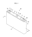
- FIG. 1 shows a perspective view illustrating a rechargeable battery according to a first exemplary embodiment of the present invention.
- FIG. 2 shows a cross-sectional view illustrating the rechargeable battery taken along line II-II of FIG. 1 .
- FIG. 3 shows an exploded perspective view illustrating an electrode assembly, a first insulation member, a safety device, and a second insulation member of FIG. 2 .
- FIG. 4 shows a cross-sectional view illustrating the electrode assembly, the first insulation member, the safety device, and the second insulation member taken along line IV-IV of FIG. 2 .
- FIG. 5 shows a partial cross-sectional view illustrating a state in which a conductor is short-circuited in the safety device of FIG. 4 .
- FIG. 6 shows a cross-sectional view illustrating a rechargeable battery according to a second exemplary embodiment of the present invention.
- FIG. 7 shows a partial cross-sectional view illustrating a state in which a conductor is short-circuited in the safety device of FIG. 6 .
- FIG. 8 shows a cross-sectional view illustrating a rechargeable battery according to a third exemplary embodiment of the present invention.
- FIG. 9 shows a partial cross-sectional view illustrating a state in which a conductor is short-circuited in the safety device of FIG. 8 .
- FIG. 10 shows a cross-sectional view illustrating a rechargeable battery according to a fourth exemplary embodiment of the present invention.
- FIG. 11 shows a partial cross-sectional view illustrating a state in which a conductor is short-circuited in the safety device of FIG. 10 .
- FIG. 12 shows a cross-sectional view illustrating a rechargeable battery according a fifth exemplary embodiment of the present invention.
- FIG. 13 shows an exploded perspective view illustrating an electrode assembly, a first insulation member, a safety device, and a second insulation member of a rechargeable battery according to a sixth exemplary embodiment of the present invention.
- FIG. 1 shows a perspective view illustrating a rechargeable battery according to a first exemplary embodiment of the present invention
- FIG. 2 shows a cross-sectional view illustrating the rechargeable battery taken along line II-II of FIG. 1
- a rechargeable battery 100 according to the first exemplary embodiment includes an electrode assembly 10 that charges and discharges a current, a case 15 that houses the electrode assembly 10, a cap plate 20 that is coupled to an opening of the case 15, and a first electrode terminal 21 (hereinafter, referred to as a "negative terminal”) and a second electrode terminal 22 (hereinafter, referred to as a "positive terminal”) that are installed in the cap plate 20.
- a first electrode terminal 21 hereinafter, referred to as a "negative terminal”
- a second electrode terminal 22 hereinafter, referred to as a "positive terminal
- the electrode assembly 10 is formed by disposing a separator 13, which is an insulator, between a first electrode 11 (hereinafter, referred to as a "negative electrode”) and a second electrode 12 (hereinafter, referred to as a "positive electrode”) and spiral-winding the negative electrode 11, the separator 13, and the positive electrode 12 in a jelly roll form.
- a separator 13 which is an insulator
- the negative electrode 11 and the positive electrode 12 include coated regions 11 a and 12a, in which an active material is applied to a current collector of a metal plate, and uncoated regions 11 b and 12b, respectively, in which an active material is not applied to a current collector of the metal plate, which are thus formed as an exposed current collector.
- the uncoated region 11 b of the negative electrode 11 is formed at an end portion of one side of the negative electrode 11, along the spiral-wound negative electrode 11.
- the uncoated region 12b of the positive electrode 12 is formed at an end portion of one side of the positive electrode 12 along the spiral-wound positive electrode 12. Therefore, in one embodiment, the uncoated regions 11 b and 12b are each disposed at both ends of the electrode assembly 10.
- the case 15 is formed in an approximately cuboid shape, and has an opening that connects an outside space to an inside space at a surface of the cuboid, through which the electrode assembly 10 is inserted into the case 15.
- the cap plate 20 is installed in the opening of the case 15, to close and seal the case 15.
- the case 15 and the cap plate 20 may be made of aluminum and may be welded together.
- the cap plate 20 may further include an electrolyte injection opening 29, a vent hole 24, and terminal holes H1 and H2.
- the electrolyte injection opening 29 may couple the cap plate 20 to the case 15 and enables injection of an electrolyte into the case 15. After injection of the electrolyte, the electrolyte injection opening 29 may be sealed by a seal stopper 27.
- the vent hole 24 may be closed and sealed by a vent plate 25.
- the vent plate 25 may be cut out and the vent hole 24 opened.
- the vent plate 25 may have a notch 25a that guides cutting out the vent plate 25.
- the negative terminal 21 and the positive terminal 22 are installed in terminal holes H1 and H2 of the cap plate 20 and are electrically connected to the electrode assembly 10. Specifically, in one embodiment the negative terminal 21 is electrically connected to the negative electrode 11 of the electrode assembly 10, and the positive terminal 22 is electrically connected to the positive electrode 12 of the electrode assembly 10. Therefore, the electrode assembly 10 can be drawn out to the outside of the case 15 through the negative terminal 21 and the positive terminal 22.
- the negative and positive terminals 21 and 22 include rivet terminals 21 a and 22a that are installed in each of the terminal holes H1 and H2 of the cap plate 20, flanges 21 b and 22b that are integrally widely formed in the rivet terminals 21 a and 22a within the cap plate 20, and plate terminals 21 c and 22c that are disposed at the outside of the cap plate 20 to be connected to the rivet terminals 21 a and 22a, respectively by riveting or welding.
- negative and positive gaskets 36 and 37 are installed between the rivet terminals 21 a and 22a of the negative and positive terminals 21 and 22 and an inner surface of the terminal holes H1 and H2 of the cap plate 20, to seal and electrically insulate the rivet terminals 21 a and 22a of the negative and positive terminals 21 and 22 and the cap plate 20, respectively.
- the negative and positive gaskets 36 and 37 are further extended between the flanges 21 b and 22b and an inner surface of the cap plate 20, to seal and electrically insulate the flanges 21 b and 22b and the cap plate 20, respectively. That is, the negative and positive gaskets 36 and 37 may be used to install the negative and positive terminals 21 and 22 in the cap plate 20, thereby preventing or reducing leakage of an electrolyte solution through the terminal holes H1 and H2.
- negative and positive lead tabs 51 and 52 electrically connect the negative and positive terminals 21 and 22 to the negative and positive electrodes 11 and 12 of the electrode assembly 10, respectively.
- the negative and positive lead tabs 51 and 52 are connected to the lower end of the rivet terminals 21 a and 22a while being supported to the flanges 21 b and 22b, respectively.
- negative and positive insulation members 61 and 62 are installed between the negative and positive lead tabs 51 and 52 and the cap plate 20, respectively, to electrically insulate the negative and positive lead tabs 51 and 52 and the cap plate 20. Further, the negative and positive insulation members 61 and 62 are coupled to the cap plate 20 at one side and enclose the negative and positive lead tabs 51 and 52, the rivet terminals 21 a and 22a, and the flanges 21 b and 22b at another side, thereby stabilizing a connection structure thereof.
- the cap plate 20 is electrically connected to the negative terminal 21 or the positive terminal 22. In the first exemplary embodiment, the cap plate 20 is electrically connected to the positive terminal 22.
- an insulation member 31 at the negative terminal 21 is installed between the plate terminal 21 c and the cap plate 20, to electrically insulate the plate terminal 21 c and the cap plate 20. In this way, the cap plate 20 can maintain electrical insulation from the negative terminal 21.
- the insulation member 31 may be interposed between the plate terminal 21 c and the cap plate 20, and may penetrate the rivet terminal 21 a. Therefore, by coupling the insulation member 31 and the plate terminal 21 c to an upper end portion of the rivet terminal 21 a and caulking the upper end portion, the insulation member 31 and the plate terminal 21 c are coupled to the upper end portion of the rivet terminal 21 a.
- the negative gasket 36 is further extended between the rivet terminal 21 a and the insulation member 31. In this way, the negative gasket 36 further reinforces sealing and electric insulation between the rivet terminal 21 a and the insulation member 31.
- a top plate 32 of the positive terminal 22 is formed with a conductive member and is installed between the plate terminal 22c and the cap plate 20, to electrically connect the plate terminal 22c and the cap plate 20. In this way, the cap plate 20 can maintain an electrical connection to the electrode assembly 10 through the positive terminal 22.
- the top plate 32 is interposed between the plate terminal 22c and the cap plate 20 and penetrates the rivet terminal 22a. Therefore, by coupling the top plate 32 and the plate terminal 22c to an upper end portion of the rivet terminal 22a and caulking the upper end portion, the top plate 32 and the plate terminal 22c are coupled to the upper end portion of the rivet terminal 22a.
- the positive gasket 37 is further extended between the rivet terminal 22a and the top plate 32. In this way, the positive gasket 37 prevents the rivet terminal 22a and the top plate 32 from being directly electrically connected. That is, the rivet terminal 22a is electrically connected to the top plate 32 through the plate terminal 22c and indirectly electrically connected to the cap plate 20 through the top plate 32.
- FIG. 3 shows an exploded perspective view illustrating an electrode assembly, a first insulation member, a safety device, and a second insulation member of FIG. 2 .
- FIG. 4 shows a cross-sectional view illustrating the electrode assembly, the first insulation member, the safety device, and the second insulation member taken along line IV-IV of FIG. 2 .
- FIG. 5 shows a partial cross-sectional view illustrating a state in which a conductor is short-circuited in the safety device of FIG. 4 .
- the rechargeable battery 100 of the first exemplary embodiment further includes a safety device 71 that is disposed between the electrode assembly 10 and the case 15.
- the safety device 71 is installed in an insulation structure between the electrode assembly 10 and the case 15.
- the safety device 71 is connected to an electrode of the electrode assembly 10 at the electrode terminal side in which the cap plate 20 is not connected. In the first exemplary embodiment, because the cap plate 20 is electrically connected to the positive terminal 22, the safety device 71 is connected to the negative electrode 11 of the electrode assembly 10 at the negative terminal 21 side.
- the safety device 71 is disposed on at least one side of the two sides of the electrode assembly 10.
- the safety device 71 is disposed on both sides of the electrode assembly 10.
- the safety device 71 includes a plate portion 711 and a protruded portion 712 that protrudes from at least one surface of the plate portion 711.
- the protruded portion 712 is formed at one surface of an outside of the plate portion 711. That is, the safety device 71 has portions that are formed in different thicknesses.
- the plate portion 711 has a set thickness and thus can maintain self-resistance of the safety device 71 to a current flowing in a plane direction. Because the protruded portion 712 is protruded from the plate portion 711, the protruded portion 712 increases penetration resistance to a current flowing in a thickness direction, while minimizing (or reducing) a decrease of self-resistance of the safety device 71.
- the safety devices 71 are provided at each of both surfaces of the electrode assembly 10.
- the safety device may be disposed at any one surface of the electrode assembly.
- a first insulation member 81 and a second insulation member 82 are disposed at both surfaces of the safety device 71.
- the first insulation member 81 may electrically insulate the safety device 71 and the electrode assembly 10 and the second insulation member 82 may electrically insulate the safety device 71 and the case 15.
- the plate portion 711 is in close contact with the first insulation member 81, and the protruded portion 712 is in close contact with the second insulation member 82.
- the plate portion 711 has a planar form and supports the first insulation member 81 to the electrode assembly 10 in a stable structure. Further, the plate portion 711 has a separation space S from the second insulation member 82 according to a gap formed by the protruded portion 712.
- the protruded portion 712 is provided to have plural portions, and the plural portions are separated from each other in a first direction (X-axis direction of FIG. 3 ) on the safety device 71, and extended in a second direction (z-axis direction) intersecting (crossing) the first direction (x-axis direction).
- the protruded portion 712 is formed in a quadrilateral-shaped cross-section structure, for example, a square-shaped or rectangular-shaped cross-section structure.
- the safety device 71 is interposed between the electrode assembly 10 and the case 15, before the electrode assembly 10 is short-circuited at the inside of the electrode assembly 10 by penetration of the conductor N, the safety device 71 is formed to cause a short circuit at the outside of the electrode assembly 10.
- the case 15 is electrically connected to the positive electrode 12 of the electrode assembly 10
- the safety device 71 is electrically connected to the negative electrode 11 of the electrode assembly 10.
- the safety device 71 is bent along the uncoated region 11 b of the negative electrode 11 of the electrode assembly 10 to be connected to the uncoated region 11 b.
- a negative lead tab may be directly connected to an uncoated region or may be connected to a safety device to be connected to an uncoated region through the safety device.
- the conductor N When a conductor N penetrates, the conductor N may penetrate the case 15 and penetrate the electrode assembly 10.
- the safety device 71 that is disposed between the case 15 and the electrode assembly 10 causes a short circuit at the outside of the electrode assembly 10 before an internal short circuit of the electrode assembly 10.
- a voltage that is charged at the electrode assembly 10 is quickly discharged at the outside of the electrode assembly 10 through the case 15, the conductor N, and the safety device 71.
- the protruded portion 712 while the protruded portion 712 directly contacts the conductor N, the protruded portion 712 has high penetration resistance to a current flowing in a thickness direction. Therefore, the protruded portion 712 is not melted and maintains an external short circuit, thereby allowing enough discharge of a current that is charged at the electrode assembly 10.
- the second insulation member 82 may have a structure that closes an upper portion. Therefore, the second insulation member 82 may have drawn-out openings 821 and 822 that draw out the negative and positive lead tabs 51 and 52 in an upper part.
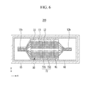
- FIG. 6 shows a cross-sectional view illustrating a rechargeable battery 200 according to a second exemplary embodiment of the present invention
- FIG. 7 shows a partial cross-sectional view illustrating a state in which a conductor is short-circuited in the safety device of FIG. 6 .
- a plate portion 721 of a safety device 72 is in close contact with a second insulation member 82
- a protruded portion 722 is in close contact with a first insulation member 81.
- the plate portion 721 has a planar form and supports the second insulation member 82 to a case 15 in a stable structure. Further, in an embodiment, the plate portion 721 has separation space S from the first insulation member 81 according to a gap formed by the protruded portion 722.
- the plate portion 721 When the conductor N penetrates, the plate portion 721 directly contacts a conductor N and has high penetration resistance to a current flowing in a thickness direction together with the protruded portion 722 of the opposite side. Therefore, the plate portion 721 is not melted and maintains an external short circuit, thereby allowing enough discharge of a current that is charged at the electrode assembly 10.
- FIG. 8 shows a cross-sectional view illustrating a rechargeable battery 300 according to a third exemplary embodiment of the present invention.
- FIG. 9 shows a partial cross-sectional view illustrating a state in which a conductor is short-circuited in the safety device of FIG. 8 .
- a safety device 73 includes a first protruded portion 732 on a first surface of the safety device and a second protruded portion 733 on a second surface of the safety device, opposite the first surface (i.e. having protruded portions at both surfaces of a plate portion 731).
- the first protruded portion 732 and the second protruded portion 733 are disposed in a symmetrical structure at both surfaces of the plate portion 731.
- the first protruded portion 732 is in close contact with a first insulation member 81
- the second protruded portion 733 is in close contact with a second insulation member 82
- the plate portion 731 has a separation space S from the first insulation member 81 according to a gap of the first protruded portion 732 and has separation space S from the second insulation member 82 according to a gap of the second protruded portion 733.
- the first protruded portion and the second protruded portion are disposed at alternate positions on the first and second surfaces of a plate portion.
- a separation space between the first insulation member and the plate portion according to a gap of the first protruded portion, and separation space between the second insulation member and the plate portion according to a gap of the second protruded portion are disposed at alternate positions.
- the second protruded portion 733 directly contacts the conductor N and has a high penetration resistance to a current flowing in a thickness direction together with the first protruded portion 732 and the plate portion 731 of the opposite side. Therefore, the plate portion 731 is not melted and maintains an external short circuit state, thereby enabling enough discharge of a current that is charged at an electrode assembly 10.
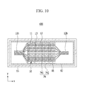
- FIG. 10 shows a cross-sectional view illustrating a rechargeable battery 400 according to a fourth exemplary embodiment of the present invention.
- FIG. 11 shows a partial cross-sectional view illustrating a state in which a conductor is short-circuited in the safety device of FIG. 10 .
- a safety device 74 includes a plate portion 741 and a protruded portion 742 that is protruded at one surface of the plate portion 741.
- the protruded portion 742 has a streamline cross-section structure.
- the plate portion 741 is in close contact with a first insulation member 81, and the protruded portion 742 is in close contact with a second insulation member 82.
- the plate portion 741 has a planar form and supports the first insulation member 81 to an electrode assembly 10 in a stable structure.
- the streamline cross-section structure of the protruded portion 742 reduces or removes separation space S between the plate portion 741 and the second insulation member 82 in spite of a gap of the protruded portion 742, thereby securely forming an adhesion structure of the safety device 74 and the second insulation member 82.
- the protruded portion 742 When the conductor N penetrates, the protruded portion 742 directly contacts the conductor N and has high penetration resistance to a current flowing in a thickness direction together with the plate portion 741. Therefore, the plate portion 741 is not melted and maintains external short circuit state, thereby enabling enough discharge of a current that is charged at the electrode assembly 10.
- FIG. 12 shows a cross-sectional view illustrating a rechargeable battery 500 according a fifth exemplary embodiment of the present invention.
- a safety device 75 includes a plate portion 751 and a protruded portion 752 that is protruded at one surface of the plate portion 751.
- the protruded portion 752 is extended in a first direction (X-axis direction of FIG. 12 ) on the safety device 75.
- the protruded portion 752 forms a maximum thickness T1 that is set in a third direction (y-axis direction) intersecting the first direction at the center of the first direction and forms a minimum thickness T2 at both ends of the first direction.
- the plate portion 751 is in close contact with the first insulation member 81, and the protruded portion 752 is in close contact with a second insulation member 82.
- the plate portion 751 has a planar form and supports the first insulation member 81 to the electrode assembly 10 in a stable structure.
- a continuous streamline cross-section structure of the protruded portion 752 securely forms an adhesion structure of the safety device 75 and the second insulation member 82. Because the safety device 75 of the fifth exemplary embodiment widely forms a range of the protruded portion 752, compared to the first to fourth exemplary embodiments, the safety device 75 may have penetration of the conductor N over a wider range.
- the protruded portion 752 When the conductor N penetrates, the protruded portion 752 directly contacts the conductor N and has high penetration resistance to a current flowing in a thickness direction together with the plate portion 751. Therefore, the plate portion 751 is not melted and maintains an external short circuit state, thereby enabling enough discharge of a current that is charged at an electrode assembly 10.
- FIG. 13 shows an exploded perspective view illustrating an electrode assembly, a first insulation member, a safety device, and a second insulation member of a rechargeable battery 600 according to a sixth exemplary embodiment of the present invention.
- a safety device 76 includes a plate portion 761 and a protruded portion 762 that is protruded at one surface of the plate portion 761.
- the protruded portion 762 may include a plurality of first protruded lines 763 and a plurality of second protruded lines 764 intersecting one surface of the plate portion 761.
- the first protruded lines 763 are separated from each other in a first direction (x-axis direction) on the safety device 76, and extended in a second direction (z-axis direction) intersecting the first direction.
- the second protruded lines 764 are separated from each other in a second direction (z-axis direction) and extended in the first direction (x-axis direction) to intersect (cross) the first protruded line 763.
- the plate portion 761 is in close contact with the first insulation member 81, and the protruded portion 762 is in close contact with a second insulation member 82.
- the plate portion 761 has a planar form and supports the first insulation member 81 to the electrode assembly 10 in a stable structure.
- the protruded portion 762 of the sixth exemplary embodiment is over a wider range, compared with the first to fourth exemplary embodiments, the protruded portion 762 corresponds to penetration of a conductor N over a wider range. Because the plate portion 761 of sixth exemplary embodiment is over a narrower range compared to the first to fourth exemplary embodiments, the protruded portion 761 corresponds to penetration of the conductor N over a narrower range.
- the first and second protruded lines 763 and 764 of the protruded portion 762 directly contact the conductor N and have high penetration resistance to a current flowing in a thickness direction together with the plate portion 761. Therefore, the first and second protruded lines 763 and 764 of the protruded portion 762 are not melted and maintain an external short circuit state, thereby enabling enough discharge of a current that is charged at the electrode assembly 10.
- electrode assembly 11 first electrode(negative electrode) 11 a, 12a: coated region 11 b, 12b: uncoated region 12: second electrode(positive electrode) 13: separator 15: case 20: cap plate 21: first electrode terminal (negative terminal) 21 a, 22a: rivet terminal 21 b, 22b: flange 21 c, 22c: plate terminal 22: second electrode terminal (positive terminal) 24: vent hole 25: vent plate 25a: notch 27: seal stopper 29: electrolyte injection opening 31: insulation member 32: top plate 36, 37: negative and positive gasket 51, 52: negative and positive lead tabs 61, 62: negative and positive insulation members 71, 72, 73, 74, 75, 76: safety device 81, 82:
Landscapes
- Chemical & Material Sciences (AREA)
- Chemical Kinetics & Catalysis (AREA)
- Electrochemistry (AREA)
- General Chemical & Material Sciences (AREA)
- Engineering & Computer Science (AREA)
- Manufacturing & Machinery (AREA)
- Connection Of Batteries Or Terminals (AREA)
Applications Claiming Priority (1)
| Application Number | Priority Date | Filing Date | Title |
|---|---|---|---|
| KR1020120133066A KR20140066284A (ko) | 2012-11-22 | 2012-11-22 | 이차 전지 |
Publications (1)
| Publication Number | Publication Date |
|---|---|
| EP2736099A1 true EP2736099A1 (de) | 2014-05-28 |
Family
ID=48537847
Family Applications (1)
| Application Number | Title | Priority Date | Filing Date |
|---|---|---|---|
| EP13170193.0A Withdrawn EP2736099A1 (de) | 2012-11-22 | 2013-06-03 | Wiederaufladbare Batterie |
Country Status (4)
| Country | Link |
|---|---|
| US (1) | US20140141294A1 (de) |
| EP (1) | EP2736099A1 (de) |
| KR (1) | KR20140066284A (de) |
| CN (1) | CN103840116A (de) |
Families Citing this family (4)
| Publication number | Priority date | Publication date | Assignee | Title |
|---|---|---|---|---|
| KR102361704B1 (ko) * | 2015-03-06 | 2022-02-09 | 삼성에스디아이 주식회사 | 이차 전지 |
| KR102439847B1 (ko) * | 2015-08-25 | 2022-09-01 | 삼성에스디아이 주식회사 | 이차 전지 |
| WO2018062339A1 (ja) | 2016-09-30 | 2018-04-05 | 三洋電機株式会社 | 角形二次電池の製造方法 |
| CN111081906B (zh) * | 2018-10-18 | 2022-03-15 | 比亚迪股份有限公司 | 电池模组、动力电池以及电动汽车 |
Citations (5)
| Publication number | Priority date | Publication date | Assignee | Title |
|---|---|---|---|---|
| JPH10261428A (ja) * | 1997-03-18 | 1998-09-29 | Japan Storage Battery Co Ltd | 電 池 |
| EP2330661A1 (de) * | 2009-12-07 | 2011-06-08 | SB LiMotive Co., Ltd. | Wiederaufladbare Batterie |
| EP2410594A1 (de) * | 2010-07-23 | 2012-01-25 | SB LiMotive Co., Ltd. | Wiederaufladbare Batterie |
| EP2439807A1 (de) * | 2010-10-08 | 2012-04-11 | SB LiMotive Co., Ltd. | Wiederaufladbare Batterie |
| US20120237809A1 (en) * | 2011-03-16 | 2012-09-20 | Samsung Sdi Co., Ltd. | Electrode assembly and secondary battery using the same |
Family Cites Families (4)
| Publication number | Priority date | Publication date | Assignee | Title |
|---|---|---|---|---|
| JP2008041264A (ja) * | 2006-08-01 | 2008-02-21 | Sony Corp | 電池および短絡部材 |
| KR101137363B1 (ko) * | 2009-11-16 | 2012-04-23 | 에스비리모티브 주식회사 | 이차전지 |
| KR101256060B1 (ko) * | 2011-06-02 | 2013-04-18 | 로베르트 보쉬 게엠베하 | 이차 전지 |
| US9627677B2 (en) * | 2011-12-23 | 2017-04-18 | Samsung Sdi Co., Ltd. | Rechargeable battery |
-
2012
- 2012-11-22 KR KR1020120133066A patent/KR20140066284A/ko not_active Ceased
-
2013
- 2013-04-19 US US13/866,709 patent/US20140141294A1/en not_active Abandoned
- 2013-06-03 EP EP13170193.0A patent/EP2736099A1/de not_active Withdrawn
- 2013-07-03 CN CN201310276470.6A patent/CN103840116A/zh active Pending
Patent Citations (5)
| Publication number | Priority date | Publication date | Assignee | Title |
|---|---|---|---|---|
| JPH10261428A (ja) * | 1997-03-18 | 1998-09-29 | Japan Storage Battery Co Ltd | 電 池 |
| EP2330661A1 (de) * | 2009-12-07 | 2011-06-08 | SB LiMotive Co., Ltd. | Wiederaufladbare Batterie |
| EP2410594A1 (de) * | 2010-07-23 | 2012-01-25 | SB LiMotive Co., Ltd. | Wiederaufladbare Batterie |
| EP2439807A1 (de) * | 2010-10-08 | 2012-04-11 | SB LiMotive Co., Ltd. | Wiederaufladbare Batterie |
| US20120237809A1 (en) * | 2011-03-16 | 2012-09-20 | Samsung Sdi Co., Ltd. | Electrode assembly and secondary battery using the same |
Also Published As
| Publication number | Publication date |
|---|---|
| KR20140066284A (ko) | 2014-06-02 |
| US20140141294A1 (en) | 2014-05-22 |
| CN103840116A (zh) | 2014-06-04 |
Similar Documents
| Publication | Publication Date | Title |
|---|---|---|
| US9478774B2 (en) | Rechargeable battery | |
| US8748031B2 (en) | Rechargeable battery having multiple cases | |
| US9819002B2 (en) | Rechargeable battery and rechargeable battery module including the same | |
| US8986878B2 (en) | Rechargeable battery including a resistance member | |
| US9799874B2 (en) | Rechargeable battery | |
| US9324989B2 (en) | Rechargeable battery including external short-circuit member | |
| US10236481B2 (en) | Rechargeable battery with connected cap plate and current collector | |
| EP2733770A1 (de) | Wiederaufladbares Batteriemodul | |
| US9692037B2 (en) | Rechargeable battery | |
| US20140227567A1 (en) | Battery module | |
| US20140272520A1 (en) | Battery module | |
| US20190207185A1 (en) | Rechargeable battery | |
| US11075434B2 (en) | Rechargeable battery | |
| US20140205877A1 (en) | Rechargeable battery | |
| US20150017496A1 (en) | Rechargeable battery pack | |
| US9865864B2 (en) | Rechargeable battery | |
| KR102416528B1 (ko) | 이차 전지 | |
| US9257694B2 (en) | Rechargeable battery having a lead tab with injection material | |
| US9653721B2 (en) | Rechargeable battery | |
| EP2736099A1 (de) | Wiederaufladbare Batterie | |
| US9887411B2 (en) | Rechargeable battery | |
| US9276252B2 (en) | Rechargeable battery | |
| US11476525B2 (en) | Rechargeable battery | |
| US9520579B2 (en) | Rechargeable battery | |
| KR101805547B1 (ko) | 커버레이를 구비한 이차 전지를 포함하는 이차 전지 팩 |
Legal Events
| Date | Code | Title | Description |
|---|---|---|---|
| PUAI | Public reference made under article 153(3) epc to a published international application that has entered the european phase |
Free format text: ORIGINAL CODE: 0009012 |
|
| 17P | Request for examination filed |
Effective date: 20130603 |
|
| AK | Designated contracting states |
Kind code of ref document: A1 Designated state(s): AL AT BE BG CH CY CZ DE DK EE ES FI FR GB GR HR HU IE IS IT LI LT LU LV MC MK MT NL NO PL PT RO RS SE SI SK SM TR |
|
| AX | Request for extension of the european patent |
Extension state: BA ME |
|
| R17P | Request for examination filed (corrected) |
Effective date: 20141114 |
|
| RBV | Designated contracting states (corrected) |
Designated state(s): AL AT BE BG CH CY CZ DE DK EE ES FI FR GB GR HR HU IE IS IT LI LT LU LV MC MK MT NL NO PL PT RO RS SE SI SK SM TR |
|
| STAA | Information on the status of an ep patent application or granted ep patent |
Free format text: STATUS: THE APPLICATION HAS BEEN WITHDRAWN |
|
| 18W | Application withdrawn |
Effective date: 20160623 |