EP2736164A2 - Verfahren zur Effizienzoptimierung eines Windgenerators durch Steuerung des Stromgenerators und System dafür - Google Patents
Verfahren zur Effizienzoptimierung eines Windgenerators durch Steuerung des Stromgenerators und System dafür Download PDFInfo
- Publication number
- EP2736164A2 EP2736164A2 EP13386032.0A EP13386032A EP2736164A2 EP 2736164 A2 EP2736164 A2 EP 2736164A2 EP 13386032 A EP13386032 A EP 13386032A EP 2736164 A2 EP2736164 A2 EP 2736164A2
- Authority
- EP
- European Patent Office
- Prior art keywords
- generator
- wind
- squirrel cage
- speed
- cage induction
- Prior art date
- Legal status (The legal status is an assumption and is not a legal conclusion. Google has not performed a legal analysis and makes no representation as to the accuracy of the status listed.)
- Granted
Links
Images


Classifications
-
- H—ELECTRICITY
- H02—GENERATION; CONVERSION OR DISTRIBUTION OF ELECTRIC POWER
- H02P—CONTROL OR REGULATION OF ELECTRIC MOTORS, ELECTRIC GENERATORS OR DYNAMO-ELECTRIC CONVERTERS; CONTROLLING TRANSFORMERS, REACTORS OR CHOKE COILS
- H02P9/00—Arrangements for controlling electric generators for the purpose of obtaining a desired output
-
- F—MECHANICAL ENGINEERING; LIGHTING; HEATING; WEAPONS; BLASTING
- F03—MACHINES OR ENGINES FOR LIQUIDS; WIND, SPRING, OR WEIGHT MOTORS; PRODUCING MECHANICAL POWER OR A REACTIVE PROPULSIVE THRUST, NOT OTHERWISE PROVIDED FOR
- F03D—WIND MOTORS
- F03D7/00—Controlling wind motors
- F03D7/02—Controlling wind motors the wind motors having rotation axis substantially parallel to the air flow entering the rotor
- F03D7/0272—Controlling wind motors the wind motors having rotation axis substantially parallel to the air flow entering the rotor by measures acting on the electrical generator
-
- H—ELECTRICITY
- H02—GENERATION; CONVERSION OR DISTRIBUTION OF ELECTRIC POWER
- H02P—CONTROL OR REGULATION OF ELECTRIC MOTORS, ELECTRIC GENERATORS OR DYNAMO-ELECTRIC CONVERTERS; CONTROLLING TRANSFORMERS, REACTORS OR CHOKE COILS
- H02P21/00—Arrangements or methods for the control of electric machines by vector control, e.g. by control of field orientation
-
- Y—GENERAL TAGGING OF NEW TECHNOLOGICAL DEVELOPMENTS; GENERAL TAGGING OF CROSS-SECTIONAL TECHNOLOGIES SPANNING OVER SEVERAL SECTIONS OF THE IPC; TECHNICAL SUBJECTS COVERED BY FORMER USPC CROSS-REFERENCE ART COLLECTIONS [XRACs] AND DIGESTS
- Y02—TECHNOLOGIES OR APPLICATIONS FOR MITIGATION OR ADAPTATION AGAINST CLIMATE CHANGE
- Y02E—REDUCTION OF GREENHOUSE GAS [GHG] EMISSIONS, RELATED TO ENERGY GENERATION, TRANSMISSION OR DISTRIBUTION
- Y02E10/00—Energy generation through renewable energy sources
- Y02E10/70—Wind energy
- Y02E10/72—Wind turbines with rotation axis in wind direction
Definitions
- This invention relates to wind generators that use induction generators (squirrel cage asynchronous generators).
- This invention discloses a method for efficiency optimization of a wind energy conversion system by controlling the electric generator. This is implemented by means of a control scheme based on the control of the generator rotor speed and achieves simultaneously maximization of the efficiencies of wind turbine and electrical generator and therefore efficiency maximization of the total wind energy conversion system.
- Main advantages of the control scheme are the simple implementation, easy installation and satisfactory quick response so as it can follow the fast changes of wind speed.
- the wind generator converts the kinetic energy of the wind into electrical energy that is provided either to an isolated electric consumer (stand-alone wind generator) or to the grid (grid connected wind generator).
- the presented invention can be applied in both cases of wind generators.
- the wind generators that are mainly used in wind energy conversion systems are squirrel cage induction generators, slip ring induction generators and permanent magnet synchronous generators.
- the presented invention is applicable to wind generators with squirrel cage induction generators and especially relates to low and medium power wind generators.
- the wind turbine provides electric energy when the wind speed is greater than a threshold, known as cut-in wind speed. If the wind speed is less than this threshold, the produced energy is not sufficient even to cover the electric and mechanical losses in the wind energy conversion system. Thus, in order to be produced maximum electric energy, the power loss should be minimized at each part of the wind system. This can be achieved by the appropriate control of the generator electric variables. Also, the proper control of the wind turbine rotor speed in relation to the respective wind speed may result in maximization of the output power. The above two goals can provide maximum efficiency of the total wind system. However, it is important that the control of the system should be simple, accurate to its result and fast in order to detect the changes of the wind speed. Also, it should not be affected the manufacturing cost and can be easily applicable to any wind generation system.
- Kioskeridis 'Maximum efficiency of a wind energy conversion system with a PM synchronous generator', in Proc. MedPower 2010 Int. Conf., pp. 1-9 and A. Mesemanolis and C. Mademlis, 'A Neural Network Based MPPT Controller for Variable Speed Wind Energy Conversion Systems', Speedam Conf. June 2012 .
- the present invention aims at providing an efficient method for efficiency optimization of a wind generator by controlling the squirrel cage induction generator that can simultaneously achieve maximum power harvesting from the wind turbine and maximum efficiency of the electric generator by means of minimizing its electric loss, comprising the following steps:
- the present invention also relates to a control scheme that controls the stator current of the electric generator and specifically, the two current components (field and torque currents) in order to achieve simultaneously maximum efficiency of the electric generator and the wind turbine and therefore maximum efficiency of the whole wind energy conversion system. Due to the above, the cut-in wind speed is reduced and therefore optimal utilization of the wind system is accomplished, since more electric energy can be produced form the existing wind energy potential.
- the main feature of the control scheme is that only the measurement of the generator rotation speed is needed which is the input to the control scheme, while the measurement of the wind speed is not required.
- the advantages of the control scheme is the fast response because the optimal values of the field and torque currents are determined through appropriate mathematical equations that serve as control conditions in the closed-loop system.
- control scheme has the capability to track the quick changes of the wind speed. It has also simple implementation and easy installation because it is not based on look-up tables that may require time consuming laboratory experiments. Moreover, it does not only burden the manufacturing cost, but needs less hardware than a standard system setup because it does not require anemometer for wind speed measurement. Therefore, the presented control scheme is a comprehensive, simple and cost-effective solution to the problem of efficiency optimization in a wind energy conversion system with squirrel cage induction generator.
- a control scheme for the rectifier converter of a wind generator with squirrel cage induction generator that implements the efficiency optimization control method above, comprising two controllers that operate simultaneously, have common input the generator speed and they determine the optimal values of the reference field and torque stator currents of the electric generator.
- the reference field component of the stator current I ds * determines the optimal magnetic flux so as loss minimization of the squirrel cage induction generator is accomplished.
- the reference torque component of the stator current I qs * determines the optimal rotational speed of the squirrel cage induction generator so as maximum power harvesting of the wind turbine is accomplished.
- the parameters G d , T a and T b are determined by the eqns. (10) below and depend on the stator and rotor resistances ( R s and R r respectively), the magnetizing and rotor inductances ( L m and L r , respectively), the iron loss coefficient C Fe and the stray loss coefficient c str of the squirrel cage induction generator.
- the parameters G q1 and G q2 are determined experimentally through curve fitting of the eqn. (20) below and also the parameter G q of said eqn. (20) is determined by the eqn. (17) below and depends on the pole pairs p and the magnetizing and rotor inductances ( L m and L r , respectively) of the squirrel cage induction generator, the air density p, the gear ratio n, the mechanical loss coefficient c m of the wind system, the radius of the blades R, the optimal value of tip speed ratio ⁇ opt and the optimal value of the aerodynamic coefficient C popt of the wind turbine.
- the rectifier converter of the wind generator with squirrel cage induction generator is implemented by a fully controlled IGBT converter that utilizes field oriented control through space-vector modulation.
- the reference field component of the stator current I ds * is regulated through a controller that implements the condition of eqn. (21) below and the input to the controller is the rotational speed ⁇ r of the squirrel cage induction generator.
- the reference torque component of the stator current I qs * is regulated through a controller that implements the condition of eqn. (22) below and the input to the controller is the rotational speed ⁇ r of the squirrel cage induction generator.
- a method for efficiency optimization of a wind generator by controlling the squirrel cage induction generator is proposed.
- the method achieves simultaneously maximum efficiency of the wind turbine (wind mill) and maximum efficiency of the electric generator through the minimization of its electric loss. Additionally, expansion of the exploitable wind speed region is accomplished through the reduction of the cut-in speed at which the wind system starts to provide power to the grid.
- the method is implemented by appropriately controlling the power rectifier and without requiring the measurement of the wind speed.
- Input to the control scheme is the rotational speed of the electric generator.
- the control scheme comprises two controllers that, for any wind speed, provide the optimal reference field and torque stator current components of the squirrel cage induction generator. The two current components are determined through optimal conditions.
- the main advantages of the presented control scheme are the quick response so as it can follow the fast changes of the wind speed and also the simple implementation and the easy installation.
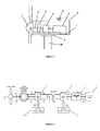
- Figure 1 shows the various parts of a typical wind generator. It consists of a wind turbine 1, a gear-box 2, an electric generator 3, a shaft 4, a brake 5, an anemometer 6 and a support frame 7.
- a wind turbine 1 it is included the blades, the hub and the nose cone.
- the shaft 4 connects the wind turbine with the gear box; whereas in case of direct driven wind turbines, the shaft connects the wind turbine with the electric generator.
- a blades pitch control system is usually installed. All the above components are installed in the nacelle 8.
- 9 is the yaw control system that adjusts the nacelle to the wind direction and 10 is the tower.
- FIG. 2 shows a control scheme of the wind generation system, through which, the invention is implemented. It consists of two back-to-back converters.
- the power converter at the generator side 1 operates as a rectifier and controls the induction generator.
- the power converter 2 operates as an inverter and converts the dc power provided by the rectifier to ac power, which after passing through an L-C-L filter 3 it is injected to the grid 4.
- the rectifier control scheme 5 and the inverter control scheme 6 operate at this invention by the vector control technique.
- the rectifier control scheme regulates the two components of the generator stator current i.e. field current I ds and torque current I qs , in order to obtain maximum power from the wind generator.
- the inverter control scheme regulates the I dN and I qN components of the output current to the grid, in order to maintain constant the dc-link voltage and to control the reactive power to the grid, respectively.
- the speed ⁇ e is the electric synchronous speed of the generator which is needed in the condition of the loss minimization controller 1 and is determined through the closed-loop control system 3. Specifically, the rotor flux-linkage ⁇ r is determined through the I ds * and then, the slip angular velocity ⁇ sl is determined by using the ⁇ r and the reference q- axis stator current I qs * . The optimal values of the electric generator stator current components I ds * and I qs * are determined through the respective optimal conditions. The above control procedure is followed for all the cases that the reference currents I ds * and I qs * are lower than their respective rated values.
- the currents I ds * and I qs * as output signals of the two controllers, cannot exceed their maximum values, because they are limited by the Limiters 5 and 6, respectively. This could be occurred either during transients or at high wind speeds.
- the electric variables of the squirrel cage induction generator are controlled by using only the mechanical speed of the rotor shaft. Consequently, the efficiency of the wind generator can be optimized by measuring only the rotor speed.
- the optimal reference values of the two stator current components are determined quickly and with satisfactory accuracy, since they are online calculated through the respective two mathematical conditions. This results in quick response of the system and thus it can follow the fast changes of the wind speed.
- the presented control scheme provides maximum efficiency of the wind energy conversion system (i.e. maximum efficiency of the wind turbine and maximum efficiency of the electric generator) and consists of two controllers that are implemented by eqs. (21) and (22), respectively.
- Input to the control scheme is the rotor speed and outputs are the references of field and torque current components of the generator stator current.
- the knowledge of the coefficients G d , G q 1 , G q 2 , T a ⁇ T b in conditions (21) and (22) is required.
- the values of the above coefficients can be determined experimentally through an off-line experimental procedure and therefore the knowledge of the exact models of the generator and wind turbine is not required.
- Figure 4 shows the implementation diagram of the invention in a 5 kW wind system.
- the wind energy is converted to kinetic energy at the shaft of the turbine 1 and through the electric generator 2 it is converted to electric power.
- the shaft speed is measured by an optical encoder 3 that is installed at the generator shaft.
- the shaft speed is needed for the implementation of the vector control in the rectifier control scheme and also for the implementation of the electric generator stator current control in order to achieve maximum efficiency in the wind system.
- the power that is produced by the generator passes through the power converter system 4 and then it is injected to the grid 5.
- the power converter system 4 is supervised by two control schemes, the rectifier control scheme 6 and the inverter control scheme 7.
- the signal of the shaft rotational speed of the squirrel cage induction generator is driven to the rectifier control scheme 6 that is implemented in a microcontroller.
- the rectifier control scheme consists of two controllers: the loss minimization controller of the electric generator 8 and the maximum power tracking controller of the wind turbine 9. Common input for both controllers is the signal of the rotational speed ⁇ r and outputs are the reference signals of the field and torque stator currents I ds * and I qs * , respectively.
- the two controllers operate simultaneously and implement the two optimal conditions of eqs. (21) and (22).
- the two controllers provide the optimal reference currents I ds * and I qs * that are determined by the two control conditions and thereby, maximum efficiency operation of the wind system can be reached in only a few cycles of the digital controller.
- the above control procedure continues for all cases that the reference currents I ds * and I qs * are less than their respective nominal values.
- the output signals I ds * and I qs * of the two controllers do not exceed their nominal values because they are constrained by the Limiters (10) and (11). This may occur during transients and in high wind speeds.
- Figure 5 compares the variation of the electric output power to the grid versus wind speed of a 5 kW wind system with the presented control technique (optimal method) against the conventional operation of the system at which only maximum power point tracking control is applied, MPPT control (conventional method). In both cases, a gear box with speed ratio 4 is used. From this diagram it is concluded that, from the same wind energy potential, the electric power production is increased by the presented optimal control scheme for all wind speed cases and also, the system starts to produce electric power from lower wind speed values (reduction of the cut-in wind speed). Specifically, the wind system with the optimal control starts to provide power to the grid from wind speed of 3.6 m/s, whereas the conventional system starts to provide power to the grid from 4.26 m/s. The above is achieved because with the proposed optimal control, maximum power from the wind turbine is accomplished and also increased percentage of the wind turbine energy is converted to electrical energy to grid, since the electric loss in the generator is minimized.
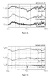
- Figures 6a and 6b show the performance of the 5 kW wind energy conversion system with the optimal control, for a time period of 2.5 min. From these figures it is resulted that the wind system exhibits quick response and satisfactory dynamic performance at the changes of the wind speed. This can be concluded from the fact that, the aerodynamic power coefficient C P has almost constant value of 0.43 that corresponds to the maximum efficiency of the wind turbine, at all wind speed cases. Also, it is validated that the optimal control scheme provides electric power to the grid at lower wind speed than 4.26 m/s, at which the conventional system starts to provide power to the grid.
Landscapes
- Engineering & Computer Science (AREA)
- Power Engineering (AREA)
- Life Sciences & Earth Sciences (AREA)
- Sustainable Development (AREA)
- Sustainable Energy (AREA)
- Chemical & Material Sciences (AREA)
- Combustion & Propulsion (AREA)
- Mechanical Engineering (AREA)
- General Engineering & Computer Science (AREA)
- Control Of Eletrric Generators (AREA)
- Wind Motors (AREA)
Applications Claiming Priority (1)
| Application Number | Priority Date | Filing Date | Title |
|---|---|---|---|
| GR20120100602A GR1008117B (el) | 2012-11-27 | 2012-11-27 | Μεθοδος βελτιστοποιησης της αποδοσης ανεμογεννητριας με ελεγχο της ηλεκτρογεννητριας |
Publications (3)
| Publication Number | Publication Date |
|---|---|
| EP2736164A2 true EP2736164A2 (de) | 2014-05-28 |
| EP2736164A3 EP2736164A3 (de) | 2015-12-09 |
| EP2736164B1 EP2736164B1 (de) | 2020-08-19 |
Family
ID=49911378
Family Applications (1)
| Application Number | Title | Priority Date | Filing Date |
|---|---|---|---|
| EP13386032.0A Active EP2736164B1 (de) | 2012-11-27 | 2013-11-27 | Verfahren zur Effizienzoptimierung eines Windgenerators durch Steuerung des Stromgenerators und System dafür |
Country Status (2)
| Country | Link |
|---|---|
| EP (1) | EP2736164B1 (de) |
| GR (1) | GR1008117B (de) |
Cited By (7)
| Publication number | Priority date | Publication date | Assignee | Title |
|---|---|---|---|---|
| CN106357178A (zh) * | 2016-09-30 | 2017-01-25 | 中车株洲电力机车研究所有限公司 | 一种低速直驱风电机组电气传动系统效率最优控制方法 |
| CN107273647A (zh) * | 2017-08-07 | 2017-10-20 | 曲阜师范大学 | 基于直流输电的低速齿轮箱双馈型风电机组优化设计方法 |
| WO2017220994A1 (en) * | 2016-06-21 | 2017-12-28 | The University Court Of The University Of Edinburgh | Control or processing system and method |
| CN111900909A (zh) * | 2020-06-17 | 2020-11-06 | 成都飞机工业(集团)有限责任公司 | 一种飞机起发一体电机的控制方法 |
| CN112523945A (zh) * | 2020-12-29 | 2021-03-19 | 重庆邮电大学 | 一种双馈风力机最大风能捕获自抗扰非线性控制方法 |
| CN116661306A (zh) * | 2023-05-08 | 2023-08-29 | 青岛理工大学 | 一种用于连续搅拌反应釜的预定义时间滑模控制方法 |
| CN118508810A (zh) * | 2024-07-18 | 2024-08-16 | 上海灵动微电子股份有限公司 | 一种电机速度控制方法、系统、计算机设备及存储介质 |
Families Citing this family (2)
| Publication number | Priority date | Publication date | Assignee | Title |
|---|---|---|---|---|
| CN110176781B (zh) * | 2019-05-24 | 2023-04-28 | 上海电力学院 | 基于隔离型变频变压器的分频输电风力发电系统及方法 |
| CN111987955B (zh) * | 2020-09-01 | 2022-06-10 | 长沙贝士德电气科技有限公司 | 用于凸极式永磁同步电机的自适应滑模控制系统及方法 |
Citations (11)
| Publication number | Priority date | Publication date | Assignee | Title |
|---|---|---|---|---|
| US4525633A (en) | 1982-09-28 | 1985-06-25 | Grumman Aerospace Corporation | Wind turbine maximum power tracking device |
| US4695736A (en) | 1985-11-18 | 1987-09-22 | United Technologies Corporation | Variable speed wind turbine |
| US5075612A (en) | 1990-01-03 | 1991-12-24 | Nikolaos Margaris | Method and device for determining the optimal excitation value which minimizes the electromagnetic losses of electric machines |
| US5155375A (en) | 1991-09-19 | 1992-10-13 | U.S. Windpower, Inc. | Speed control system for a variable speed wind turbine |
| US6711556B1 (en) | 1999-09-30 | 2004-03-23 | Ford Global Technologies, Llc | Fuzzy logic controller optimization |
| US7095131B2 (en) | 1997-08-08 | 2006-08-22 | General Electric Company | Variable speed wind turbine generator |
| US7304400B2 (en) | 2002-12-27 | 2007-12-04 | Kabushiki Kaisha Yasakawa Denki | Power generating system and its control method |
| US7312592B2 (en) | 2004-04-26 | 2007-12-25 | Maslov Boris A | Adaptive system for optimizing excitation current waveform profiles for electric motors |
| US7798631B2 (en) | 2007-07-23 | 2010-09-21 | Xerox Corporation | System and method for lubricating a transfer roller with an image member |
| US7854283B2 (en) | 1998-04-03 | 2010-12-21 | Rockwell Collins Control Technologies, Inc. | Optimization method for power generation systems |
| US8098054B2 (en) | 2007-10-10 | 2012-01-17 | John Alexander Verschuur | Optimal load controller method and device |
-
2012
- 2012-11-27 GR GR20120100602A patent/GR1008117B/el active IP Right Grant
-
2013
- 2013-11-27 EP EP13386032.0A patent/EP2736164B1/de active Active
Patent Citations (11)
| Publication number | Priority date | Publication date | Assignee | Title |
|---|---|---|---|---|
| US4525633A (en) | 1982-09-28 | 1985-06-25 | Grumman Aerospace Corporation | Wind turbine maximum power tracking device |
| US4695736A (en) | 1985-11-18 | 1987-09-22 | United Technologies Corporation | Variable speed wind turbine |
| US5075612A (en) | 1990-01-03 | 1991-12-24 | Nikolaos Margaris | Method and device for determining the optimal excitation value which minimizes the electromagnetic losses of electric machines |
| US5155375A (en) | 1991-09-19 | 1992-10-13 | U.S. Windpower, Inc. | Speed control system for a variable speed wind turbine |
| US7095131B2 (en) | 1997-08-08 | 2006-08-22 | General Electric Company | Variable speed wind turbine generator |
| US7854283B2 (en) | 1998-04-03 | 2010-12-21 | Rockwell Collins Control Technologies, Inc. | Optimization method for power generation systems |
| US6711556B1 (en) | 1999-09-30 | 2004-03-23 | Ford Global Technologies, Llc | Fuzzy logic controller optimization |
| US7304400B2 (en) | 2002-12-27 | 2007-12-04 | Kabushiki Kaisha Yasakawa Denki | Power generating system and its control method |
| US7312592B2 (en) | 2004-04-26 | 2007-12-25 | Maslov Boris A | Adaptive system for optimizing excitation current waveform profiles for electric motors |
| US7798631B2 (en) | 2007-07-23 | 2010-09-21 | Xerox Corporation | System and method for lubricating a transfer roller with an image member |
| US8098054B2 (en) | 2007-10-10 | 2012-01-17 | John Alexander Verschuur | Optimal load controller method and device |
Non-Patent Citations (12)
| Title |
|---|
| A. G. ABO-KHALIL: "Model-based optimal efficiency control of induction generator for wind power systems", PROC. CONF. REC. ICIT-2011, 2011, pages 191 - 197, XP031943455, DOI: doi:10.1109/ICIT.2011.5754371 |
| A. G. ABO-KHALIL; H. G. KIM; D. C. LEE; J. K. SEOK: "Maximum output power control of wind generation system considering loss minimization machines", PROC. IEEE INT. CONF. IECON, 2004, pages 1676 - 1681, XP010798992, DOI: doi:10.1109/IECON.2004.1431833 |
| A. MESEMANOLIS; C. MADEMLIS: "A Neural Network Based MPPT Controller for Variable Speed Wind Energy Conversion Systems", SPEEDAM CONF., June 2012 (2012-06-01) |
| A. MESEMANOLIS; C. MADEMLIS; 1. KIOSKERIDIS: "Maximum efficiency of a wind energy conversion system with a PM synchronous generator", PROC. MEDPOWER 2010 INT. CONF., 2010, pages 1 - 9 |
| A. MESEMANOLIS; C. MADEMLIS; I, KIOSKERIDIS: "Maximum electrical energy production of a variable speed wind energy conversion system", PROC. IEEE INT. SYMPOSIUM ISIE, 2012, pages 1029 - 1034, XP032199857, DOI: doi:10.1109/ISIE.2012.6237230 |
| M. CHINCHILLA; S. ARNALTES; J. C. BURGOS: "Control of permanent-magnet generators applied to variable-speed wind-energy systems connected to the grid", IEEE TRANS. ENERGY CONVERS., vol. 21, no. 1, March 2006 (2006-03-01), pages 130 - 135 |
| M. PUCCI; M. CIRRINCIONE: "Neural MPPT control of generators with induction machines with-out speed sensors", IEEE TRANS. IND. ELECTRON., vol. 58, no. 1, January 2011 (2011-01-01), pages 37 - 47, XP011338445, DOI: doi:10.1109/TIE.2010.2043043 |
| MUNTEANU, S. BACHA; A. 1. BRATCU; J. GUIRAUD; D. ROYE: "Energy-reliability optimization of wind energy conversion systems by sliding mode control", IEEE TRANS. ENERGY CONVERS., vol. 23, no. 3, September 2008 (2008-09-01), pages 975 - 984, XP011229748, DOI: doi:10.1109/TEC.2008.917102 |
| R. DATTA; V. T. RANGANATHAN: "A method of tracking the peak power points for a variable speed wind energy conversion system", IEEE TRANS. ENERGY CONVERS., vol. 18, no. 1, March 2003 (2003-03-01), pages 163 - 168, XP011072136 |
| R.M. HILLOOWALA; A.M. SHARAF: "A rule-based fuzzy logic controller for a PWM inverter in a stand-alone wind energy conversion scheme", IEEE TRANS. IND. APPL., vol. 32, no. 1, January 1996 (1996-01-01), pages 57 - 65, XP000559408, DOI: doi:10.1109/28.485813 |
| V. GALDI; A. PICCOLO; P. SIANO: "Designing an adaptive fuzzy controller for maximum wind energy extraction", IEEE TRANS. ENERGY CONVERS., vol. 23, no. 2, June 2008 (2008-06-01), pages 559 - 569, XP011205023 |
| W. QIAO; L. QU; R. G. HARLEY: "Control of IPM synchronous generator for maximum wind power generation considering magnetic saturation", IEEE TRANS. IND. APPL., vol. 45, no. 3, May 2009 (2009-05-01), pages 1095 - 1105, XP011257916 |
Cited By (13)
| Publication number | Priority date | Publication date | Assignee | Title |
|---|---|---|---|---|
| CN109642536B (zh) * | 2016-06-21 | 2021-10-01 | 能源启用解决方案有限公司 | 控制或处理系统和方法 |
| WO2017220994A1 (en) * | 2016-06-21 | 2017-12-28 | The University Court Of The University Of Edinburgh | Control or processing system and method |
| GB2551701A (en) * | 2016-06-21 | 2018-01-03 | Univ Court Univ Of Edinburgh | Control or processing system and method |
| CN109642536A (zh) * | 2016-06-21 | 2019-04-16 | 能源启用解决方案有限公司 | 控制或处理系统和方法 |
| US11359598B2 (en) | 2016-06-21 | 2022-06-14 | Power Enable Solutions Limited | System and method for determining a target power and/or target torque of an energy conversion device |
| CN106357178B (zh) * | 2016-09-30 | 2018-09-18 | 中车株洲电力机车研究所有限公司 | 一种低速直驱风电机组电气传动系统效率最优控制方法 |
| CN106357178A (zh) * | 2016-09-30 | 2017-01-25 | 中车株洲电力机车研究所有限公司 | 一种低速直驱风电机组电气传动系统效率最优控制方法 |
| CN107273647A (zh) * | 2017-08-07 | 2017-10-20 | 曲阜师范大学 | 基于直流输电的低速齿轮箱双馈型风电机组优化设计方法 |
| CN107273647B (zh) * | 2017-08-07 | 2020-08-11 | 曲阜师范大学 | 基于直流输电的低速齿轮箱双馈型风电机组优化设计方法 |
| CN111900909A (zh) * | 2020-06-17 | 2020-11-06 | 成都飞机工业(集团)有限责任公司 | 一种飞机起发一体电机的控制方法 |
| CN112523945A (zh) * | 2020-12-29 | 2021-03-19 | 重庆邮电大学 | 一种双馈风力机最大风能捕获自抗扰非线性控制方法 |
| CN116661306A (zh) * | 2023-05-08 | 2023-08-29 | 青岛理工大学 | 一种用于连续搅拌反应釜的预定义时间滑模控制方法 |
| CN118508810A (zh) * | 2024-07-18 | 2024-08-16 | 上海灵动微电子股份有限公司 | 一种电机速度控制方法、系统、计算机设备及存储介质 |
Also Published As
| Publication number | Publication date |
|---|---|
| EP2736164B1 (de) | 2020-08-19 |
| GR1008117B (el) | 2014-02-12 |
| EP2736164A3 (de) | 2015-12-09 |
Similar Documents
| Publication | Publication Date | Title |
|---|---|---|
| EP2736164B1 (de) | Verfahren zur Effizienzoptimierung eines Windgenerators durch Steuerung des Stromgenerators und System dafür | |
| Thongam et al. | Wind speed sensorless maximum power point tracking control of variable speed wind energy conversion systems | |
| Hansen et al. | Control of variable speed wind turbines with doubly-fed induction generators | |
| Song et al. | Implementation and control of grid connected AC-DC-AC power converter for variable speed wind energy conversion system | |
| He et al. | Adaptive multi-mode power control of a direct-drive PM wind generation system in a microgrid | |
| CN104481803B (zh) | 一种风力发电系统追踪最大输出功率控制方法 | |
| Buticchi et al. | Active rectifier with integrated system control for microwind power systems | |
| Youssef et al. | MPPT control technique for direct-drive five-phase PMSG wind turbines with wind speed estimation | |
| CN110360051A (zh) | 一种小型定桨永磁同步风力发电机组控制器 | |
| Yang et al. | Modeling and control of the PMSG wind generation system with a novel controller | |
| Gajewski et al. | Direct Torque Control and Direct Power Control of wind turbine system with PMSG. | |
| Fengxiang et al. | Study on control system of low speed PM generator direct driven by wind turbine | |
| Gajewski et al. | Analysis of a wind energy converter system with pm sg generator | |
| Linus et al. | Maximum power point tracking and grid feeding of permanent magnet synchronous generator based wind energy conversion system using modified hill climb searching algorithm | |
| Putri et al. | Modeling and control of permanent magnet synchronous generator variable speed wind turbine | |
| Serhoud et al. | Maximal wind energy tracing of brushless doubly-fed generator under flux oriented vector control | |
| Thongam et al. | A method of tracking maximum power points in variable speed wind energy conversion systems | |
| Alaboudy et al. | Controller performance of variable speed wind driven doubly-fed induction generator | |
| Tan et al. | Mechanical sensorless robust control of wind turbine driven permanent magnet synchronous generator for maximum power operation | |
| Pradhan et al. | Real-time active and reactive power control of a doubly-fed induction generator based wind energy conversion system | |
| Yonis et al. | Dynamic Analysis of Current Loops Behavior in a Wind Turbine Based Doubly-fed Induction Generator | |
| Mosaddegh et al. | Variable structure direct torque control of brushless doubly fed induction generator for wind turbine applications | |
| Kante et al. | A review paper on modeling and simulation of permanent magnet synchronous generator based on wind energy conversion system | |
| Linus et al. | Maximum power point tracking of PMSG based grid connected WECS using quadrature axis current | |
| Elhaji et al. | Comparative Analysis of Controls in Permanent Magnet Synchronous Generator-Based Wind Turbines |
Legal Events
| Date | Code | Title | Description |
|---|---|---|---|
| PUAI | Public reference made under article 153(3) epc to a published international application that has entered the european phase |
Free format text: ORIGINAL CODE: 0009012 |
|
| 17P | Request for examination filed |
Effective date: 20131127 |
|
| AK | Designated contracting states |
Kind code of ref document: A2 Designated state(s): AL AT BE BG CH CY CZ DE DK EE ES FI FR GB GR HR HU IE IS IT LI LT LU LV MC MK MT NL NO PL PT RO RS SE SI SK SM TR |
|
| AX | Request for extension of the european patent |
Extension state: BA ME |
|
| PUAL | Search report despatched |
Free format text: ORIGINAL CODE: 0009013 |
|
| AK | Designated contracting states |
Kind code of ref document: A3 Designated state(s): AL AT BE BG CH CY CZ DE DK EE ES FI FR GB GR HR HU IE IS IT LI LT LU LV MC MK MT NL NO PL PT RO RS SE SI SK SM TR |
|
| AX | Request for extension of the european patent |
Extension state: BA ME |
|
| RIC1 | Information provided on ipc code assigned before grant |
Ipc: H02P 9/00 20060101AFI20151102BHEP Ipc: H02P 21/00 20060101ALI20151102BHEP |
|
| R17P | Request for examination filed (corrected) |
Effective date: 20160525 |
|
| RBV | Designated contracting states (corrected) |
Designated state(s): AL AT BE BG CH CY CZ DE DK EE ES FI FR GB GR HR HU IE IS IT LI LT LU LV MC MK MT NL NO PL PT RO RS SE SI SK SM TR |
|
| STAA | Information on the status of an ep patent application or granted ep patent |
Free format text: STATUS: EXAMINATION IS IN PROGRESS |
|
| 17Q | First examination report despatched |
Effective date: 20190128 |
|
| RAP1 | Party data changed (applicant data changed or rights of an application transferred) |
Owner name: ALEXANDER TECHNOLOGICAL EDUCATIONAL INSTITUTE OF T Owner name: KIOSKERIDIS, IORDANIS Owner name: MADEMLIS, CHRISTOS Owner name: ARISTOTLE UNIVERSITY OF THESSALONIKI-RESEARCH COMM |
|
| GRAP | Despatch of communication of intention to grant a patent |
Free format text: ORIGINAL CODE: EPIDOSNIGR1 |
|
| GRAJ | Information related to disapproval of communication of intention to grant by the applicant or resumption of examination proceedings by the epo deleted |
Free format text: ORIGINAL CODE: EPIDOSDIGR1 |
|
| GRAP | Despatch of communication of intention to grant a patent |
Free format text: ORIGINAL CODE: EPIDOSNIGR1 |
|
| STAA | Information on the status of an ep patent application or granted ep patent |
Free format text: STATUS: GRANT OF PATENT IS INTENDED |
|
| INTG | Intention to grant announced |
Effective date: 20200219 |
|
| INTC | Intention to grant announced (deleted) | ||
| INTG | Intention to grant announced |
Effective date: 20200303 |
|
| GRAS | Grant fee paid |
Free format text: ORIGINAL CODE: EPIDOSNIGR3 |
|
| GRAA | (expected) grant |
Free format text: ORIGINAL CODE: 0009210 |
|
| STAA | Information on the status of an ep patent application or granted ep patent |
Free format text: STATUS: THE PATENT HAS BEEN GRANTED |
|
| RIN1 | Information on inventor provided before grant (corrected) |
Inventor name: MADEMLIS, CHRISTOS Inventor name: KIOSKERIDIS, IORDANIS |
|
| AK | Designated contracting states |
Kind code of ref document: B1 Designated state(s): AL AT BE BG CH CY CZ DE DK EE ES FI FR GB GR HR HU IE IS IT LI LT LU LV MC MK MT NL NO PL PT RO RS SE SI SK SM TR |
|
| RAP1 | Party data changed (applicant data changed or rights of an application transferred) |
Owner name: SPECIAL ACCOUNT MANAGEMENT COMMITTEE OF INTERNATIONAL HELLENIC UNIVERSITY Owner name: KIOSKERIDIS, IORDANIS Owner name: MADEMLIS, CHRISTOS Owner name: ARISTOTLE UNIVERSITY OF THESSALONIKI-RESEARCH COMMITTEE |
|
| REG | Reference to a national code |
Ref country code: GB Ref legal event code: FG4D |
|
| REG | Reference to a national code |
Ref country code: CH Ref legal event code: EP |
|
| REG | Reference to a national code |
Ref country code: DE Ref legal event code: R096 Ref document number: 602013071733 Country of ref document: DE |
|
| REG | Reference to a national code |
Ref country code: AT Ref legal event code: REF Ref document number: 1305098 Country of ref document: AT Kind code of ref document: T Effective date: 20200915 |
|
| REG | Reference to a national code |
Ref country code: IE Ref legal event code: FG4D |
|
| REG | Reference to a national code |
Ref country code: LT Ref legal event code: MG4D |
|
| REG | Reference to a national code |
Ref country code: NL Ref legal event code: MP Effective date: 20200819 |
|
| PG25 | Lapsed in a contracting state [announced via postgrant information from national office to epo] |
Ref country code: FI Free format text: LAPSE BECAUSE OF FAILURE TO SUBMIT A TRANSLATION OF THE DESCRIPTION OR TO PAY THE FEE WITHIN THE PRESCRIBED TIME-LIMIT Effective date: 20200819 Ref country code: PT Free format text: LAPSE BECAUSE OF FAILURE TO SUBMIT A TRANSLATION OF THE DESCRIPTION OR TO PAY THE FEE WITHIN THE PRESCRIBED TIME-LIMIT Effective date: 20201221 Ref country code: LT Free format text: LAPSE BECAUSE OF FAILURE TO SUBMIT A TRANSLATION OF THE DESCRIPTION OR TO PAY THE FEE WITHIN THE PRESCRIBED TIME-LIMIT Effective date: 20200819 Ref country code: BG Free format text: LAPSE BECAUSE OF FAILURE TO SUBMIT A TRANSLATION OF THE DESCRIPTION OR TO PAY THE FEE WITHIN THE PRESCRIBED TIME-LIMIT Effective date: 20201119 Ref country code: NO Free format text: LAPSE BECAUSE OF FAILURE TO SUBMIT A TRANSLATION OF THE DESCRIPTION OR TO PAY THE FEE WITHIN THE PRESCRIBED TIME-LIMIT Effective date: 20201119 Ref country code: HR Free format text: LAPSE BECAUSE OF FAILURE TO SUBMIT A TRANSLATION OF THE DESCRIPTION OR TO PAY THE FEE WITHIN THE PRESCRIBED TIME-LIMIT Effective date: 20200819 Ref country code: SE Free format text: LAPSE BECAUSE OF FAILURE TO SUBMIT A TRANSLATION OF THE DESCRIPTION OR TO PAY THE FEE WITHIN THE PRESCRIBED TIME-LIMIT Effective date: 20200819 |
|
| PGFP | Annual fee paid to national office [announced via postgrant information from national office to epo] |
Ref country code: IE Payment date: 20201126 Year of fee payment: 8 Ref country code: FR Payment date: 20201126 Year of fee payment: 8 Ref country code: GR Payment date: 20201130 Year of fee payment: 8 |
|
| REG | Reference to a national code |
Ref country code: AT Ref legal event code: MK05 Ref document number: 1305098 Country of ref document: AT Kind code of ref document: T Effective date: 20200819 |
|
| PG25 | Lapsed in a contracting state [announced via postgrant information from national office to epo] |
Ref country code: PL Free format text: LAPSE BECAUSE OF FAILURE TO SUBMIT A TRANSLATION OF THE DESCRIPTION OR TO PAY THE FEE WITHIN THE PRESCRIBED TIME-LIMIT Effective date: 20200819 Ref country code: LV Free format text: LAPSE BECAUSE OF FAILURE TO SUBMIT A TRANSLATION OF THE DESCRIPTION OR TO PAY THE FEE WITHIN THE PRESCRIBED TIME-LIMIT Effective date: 20200819 Ref country code: RS Free format text: LAPSE BECAUSE OF FAILURE TO SUBMIT A TRANSLATION OF THE DESCRIPTION OR TO PAY THE FEE WITHIN THE PRESCRIBED TIME-LIMIT Effective date: 20200819 Ref country code: NL Free format text: LAPSE BECAUSE OF FAILURE TO SUBMIT A TRANSLATION OF THE DESCRIPTION OR TO PAY THE FEE WITHIN THE PRESCRIBED TIME-LIMIT Effective date: 20200819 Ref country code: IS Free format text: LAPSE BECAUSE OF FAILURE TO SUBMIT A TRANSLATION OF THE DESCRIPTION OR TO PAY THE FEE WITHIN THE PRESCRIBED TIME-LIMIT Effective date: 20201219 |
|
| PGFP | Annual fee paid to national office [announced via postgrant information from national office to epo] |
Ref country code: BE Payment date: 20201126 Year of fee payment: 8 |
|
| PG25 | Lapsed in a contracting state [announced via postgrant information from national office to epo] |
Ref country code: CZ Free format text: LAPSE BECAUSE OF FAILURE TO SUBMIT A TRANSLATION OF THE DESCRIPTION OR TO PAY THE FEE WITHIN THE PRESCRIBED TIME-LIMIT Effective date: 20200819 Ref country code: DK Free format text: LAPSE BECAUSE OF FAILURE TO SUBMIT A TRANSLATION OF THE DESCRIPTION OR TO PAY THE FEE WITHIN THE PRESCRIBED TIME-LIMIT Effective date: 20200819 Ref country code: EE Free format text: LAPSE BECAUSE OF FAILURE TO SUBMIT A TRANSLATION OF THE DESCRIPTION OR TO PAY THE FEE WITHIN THE PRESCRIBED TIME-LIMIT Effective date: 20200819 Ref country code: RO Free format text: LAPSE BECAUSE OF FAILURE TO SUBMIT A TRANSLATION OF THE DESCRIPTION OR TO PAY THE FEE WITHIN THE PRESCRIBED TIME-LIMIT Effective date: 20200819 Ref country code: SM Free format text: LAPSE BECAUSE OF FAILURE TO SUBMIT A TRANSLATION OF THE DESCRIPTION OR TO PAY THE FEE WITHIN THE PRESCRIBED TIME-LIMIT Effective date: 20200819 |
|
| REG | Reference to a national code |
Ref country code: DE Ref legal event code: R097 Ref document number: 602013071733 Country of ref document: DE |
|
| PG25 | Lapsed in a contracting state [announced via postgrant information from national office to epo] |
Ref country code: ES Free format text: LAPSE BECAUSE OF FAILURE TO SUBMIT A TRANSLATION OF THE DESCRIPTION OR TO PAY THE FEE WITHIN THE PRESCRIBED TIME-LIMIT Effective date: 20200819 Ref country code: AT Free format text: LAPSE BECAUSE OF FAILURE TO SUBMIT A TRANSLATION OF THE DESCRIPTION OR TO PAY THE FEE WITHIN THE PRESCRIBED TIME-LIMIT Effective date: 20200819 Ref country code: AL Free format text: LAPSE BECAUSE OF FAILURE TO SUBMIT A TRANSLATION OF THE DESCRIPTION OR TO PAY THE FEE WITHIN THE PRESCRIBED TIME-LIMIT Effective date: 20200819 |
|
| PLBE | No opposition filed within time limit |
Free format text: ORIGINAL CODE: 0009261 |
|
| STAA | Information on the status of an ep patent application or granted ep patent |
Free format text: STATUS: NO OPPOSITION FILED WITHIN TIME LIMIT |
|
| PG25 | Lapsed in a contracting state [announced via postgrant information from national office to epo] |
Ref country code: MC Free format text: LAPSE BECAUSE OF FAILURE TO SUBMIT A TRANSLATION OF THE DESCRIPTION OR TO PAY THE FEE WITHIN THE PRESCRIBED TIME-LIMIT Effective date: 20200819 Ref country code: SK Free format text: LAPSE BECAUSE OF FAILURE TO SUBMIT A TRANSLATION OF THE DESCRIPTION OR TO PAY THE FEE WITHIN THE PRESCRIBED TIME-LIMIT Effective date: 20200819 |
|
| 26N | No opposition filed |
Effective date: 20210520 |
|
| PG25 | Lapsed in a contracting state [announced via postgrant information from national office to epo] |
Ref country code: LU Free format text: LAPSE BECAUSE OF NON-PAYMENT OF DUE FEES Effective date: 20201127 Ref country code: IT Free format text: LAPSE BECAUSE OF FAILURE TO SUBMIT A TRANSLATION OF THE DESCRIPTION OR TO PAY THE FEE WITHIN THE PRESCRIBED TIME-LIMIT Effective date: 20200819 |
|
| PGFP | Annual fee paid to national office [announced via postgrant information from national office to epo] |
Ref country code: DE Payment date: 20210521 Year of fee payment: 8 |
|
| PG25 | Lapsed in a contracting state [announced via postgrant information from national office to epo] |
Ref country code: SI Free format text: LAPSE BECAUSE OF FAILURE TO SUBMIT A TRANSLATION OF THE DESCRIPTION OR TO PAY THE FEE WITHIN THE PRESCRIBED TIME-LIMIT Effective date: 20200819 |
|
| PGFP | Annual fee paid to national office [announced via postgrant information from national office to epo] |
Ref country code: CH Payment date: 20210521 Year of fee payment: 8 Ref country code: GB Payment date: 20210521 Year of fee payment: 8 |
|
| PG25 | Lapsed in a contracting state [announced via postgrant information from national office to epo] |
Ref country code: TR Free format text: LAPSE BECAUSE OF FAILURE TO SUBMIT A TRANSLATION OF THE DESCRIPTION OR TO PAY THE FEE WITHIN THE PRESCRIBED TIME-LIMIT Effective date: 20200819 Ref country code: MT Free format text: LAPSE BECAUSE OF FAILURE TO SUBMIT A TRANSLATION OF THE DESCRIPTION OR TO PAY THE FEE WITHIN THE PRESCRIBED TIME-LIMIT Effective date: 20200819 Ref country code: CY Free format text: LAPSE BECAUSE OF FAILURE TO SUBMIT A TRANSLATION OF THE DESCRIPTION OR TO PAY THE FEE WITHIN THE PRESCRIBED TIME-LIMIT Effective date: 20200819 |
|
| REG | Reference to a national code |
Ref country code: DE Ref legal event code: R119 Ref document number: 602013071733 Country of ref document: DE |
|
| PG25 | Lapsed in a contracting state [announced via postgrant information from national office to epo] |
Ref country code: MK Free format text: LAPSE BECAUSE OF FAILURE TO SUBMIT A TRANSLATION OF THE DESCRIPTION OR TO PAY THE FEE WITHIN THE PRESCRIBED TIME-LIMIT Effective date: 20200819 |
|
| REG | Reference to a national code |
Ref country code: CH Ref legal event code: PL |
|
| GBPC | Gb: european patent ceased through non-payment of renewal fee |
Effective date: 20211127 |
|
| PG25 | Lapsed in a contracting state [announced via postgrant information from national office to epo] |
Ref country code: BE Free format text: LAPSE BECAUSE OF NON-PAYMENT OF DUE FEES Effective date: 20211130 |
|
| REG | Reference to a national code |
Ref country code: BE Ref legal event code: MM Effective date: 20211130 |
|
| PG25 | Lapsed in a contracting state [announced via postgrant information from national office to epo] |
Ref country code: GR Free format text: LAPSE BECAUSE OF NON-PAYMENT OF DUE FEES Effective date: 20220607 |
|
| PG25 | Lapsed in a contracting state [announced via postgrant information from national office to epo] |
Ref country code: IE Free format text: LAPSE BECAUSE OF NON-PAYMENT OF DUE FEES Effective date: 20211127 Ref country code: GB Free format text: LAPSE BECAUSE OF NON-PAYMENT OF DUE FEES Effective date: 20211127 Ref country code: DE Free format text: LAPSE BECAUSE OF NON-PAYMENT OF DUE FEES Effective date: 20220601 |
|
| PG25 | Lapsed in a contracting state [announced via postgrant information from national office to epo] |
Ref country code: FR Free format text: LAPSE BECAUSE OF NON-PAYMENT OF DUE FEES Effective date: 20211130 |
|
| PG25 | Lapsed in a contracting state [announced via postgrant information from national office to epo] |
Ref country code: LI Free format text: LAPSE BECAUSE OF NON-PAYMENT OF DUE FEES Effective date: 20220701 Ref country code: CH Free format text: LAPSE BECAUSE OF NON-PAYMENT OF DUE FEES Effective date: 20220701 |