EP2736292B1 - Procédé d'acquisition de synchronisation temporelle dans des réseaux hétérogènes et appareil pour ledit procédé - Google Patents
Procédé d'acquisition de synchronisation temporelle dans des réseaux hétérogènes et appareil pour ledit procédé Download PDFInfo
- Publication number
- EP2736292B1 EP2736292B1 EP12815065.3A EP12815065A EP2736292B1 EP 2736292 B1 EP2736292 B1 EP 2736292B1 EP 12815065 A EP12815065 A EP 12815065A EP 2736292 B1 EP2736292 B1 EP 2736292B1
- Authority
- EP
- European Patent Office
- Prior art keywords
- base station
- synchronization
- synchronization channel
- henb
- user equipment
- Prior art date
- Legal status (The legal status is an assumption and is not a legal conclusion. Google has not performed a legal analysis and makes no representation as to the accuracy of the status listed.)
- Not-in-force
Links
- 238000000034 method Methods 0.000 title claims description 48
- 230000005540 biological transmission Effects 0.000 claims description 45
- 238000004891 communication Methods 0.000 claims description 24
- 230000008569 process Effects 0.000 claims description 18
- 238000001514 detection method Methods 0.000 claims description 8
- 238000010586 diagram Methods 0.000 description 14
- 238000012544 monitoring process Methods 0.000 description 7
- 230000011664 signaling Effects 0.000 description 6
- 241000760358 Enodes Species 0.000 description 5
- 230000000694 effects Effects 0.000 description 5
- 230000008054 signal transmission Effects 0.000 description 4
- 239000013256 coordination polymer Substances 0.000 description 3
- 238000005516 engineering process Methods 0.000 description 3
- 230000006870 function Effects 0.000 description 3
- 230000000116 mitigating effect Effects 0.000 description 3
- 238000010295 mobile communication Methods 0.000 description 3
- 230000004044 response Effects 0.000 description 3
- 238000013507 mapping Methods 0.000 description 2
- 238000012986 modification Methods 0.000 description 2
- 230000004048 modification Effects 0.000 description 2
- 230000036962 time dependent Effects 0.000 description 2
- 101000741965 Homo sapiens Inactive tyrosine-protein kinase PRAG1 Proteins 0.000 description 1
- 102100038659 Inactive tyrosine-protein kinase PRAG1 Human genes 0.000 description 1
- 238000003491 array Methods 0.000 description 1
- 239000000969 carrier Substances 0.000 description 1
- 230000007774 longterm Effects 0.000 description 1
- 238000010801 machine learning Methods 0.000 description 1
- 239000011159 matrix material Substances 0.000 description 1
- 238000005259 measurement Methods 0.000 description 1
- 238000012545 processing Methods 0.000 description 1
- 230000001105 regulatory effect Effects 0.000 description 1
- 239000002699 waste material Substances 0.000 description 1
Images


Classifications
-
- H—ELECTRICITY
- H04—ELECTRIC COMMUNICATION TECHNIQUE
- H04W—WIRELESS COMMUNICATION NETWORKS
- H04W56/00—Synchronisation arrangements
-
- H—ELECTRICITY
- H04—ELECTRIC COMMUNICATION TECHNIQUE
- H04W—WIRELESS COMMUNICATION NETWORKS
- H04W56/00—Synchronisation arrangements
- H04W56/001—Synchronization between nodes
- H04W56/0015—Synchronization between nodes one node acting as a reference for the others
-
- H—ELECTRICITY
- H04—ELECTRIC COMMUNICATION TECHNIQUE
- H04W—WIRELESS COMMUNICATION NETWORKS
- H04W24/00—Supervisory, monitoring or testing arrangements
- H04W24/02—Arrangements for optimising operational condition
Definitions
- the present invention relates to a wireless communication system, and more particularly, to a method of mitigating inter-cell interference and apparatus therefor.
- a wireless communication system is developing to diversely cover a wide range to provide such a communication service as an audio communication service, a data communication service and the like.
- the wireless communication is a sort of a multiple access system capable of supporting communications with multiple users by sharing available system resources (e.g., bandwidth, transmit power, etc.).
- the multiple access system may include one of CDMA (code division multiple access) system, FDMA (frequency division multiple access) system, TDMA (time division multiple access) system, OFDMA (orthogonal frequency division multiple access) system, SC-FDMA (single carrier frequency division multiple access) system and the like.
- US 2009/0280819 A1 discloses system(s) and method(s) which are provided to manage signaling in a femto cell access point.
- a pilot signal power profile or pilot signal gating, determines transmitted a time-dependent pilot signal power.
- the power profile displays a duty cycle well below 100% and a power depth, which is the amplitude between maximum and minimum pilot signal power, determined partially upon radio link conditions.
- the time-dependent power profile can be established through a schedule based at least in part on attachment data or subscriber input; machine-learning method facilitate inferring the schedule.
- Pilot signal gating profile can be reused in a femto cell deployment to broaden femto cell identification and thus facilitate macro-to-femto handover.
- a method of acquiring time synchronization in a wireless communication system includes the steps of obtaining information on a non-contiguous transmission pattern of a synchronization channel, detecting a synchronization channel of a base station, and re-detecting of the synchronization channel of the base station for a predetermined time if the detection process fails, wherein if the base station corresponds to a first type, the predetermined time is equal to or greater than a duration for which a synchronization channel is not contiguously transmitted in the non-contiguous transmission pattern, and wherein if the base station corresponds to a second type, the predetermined time is equal to or greater than a duration for which a synchronization channel is contiguously transmitted in the non-contiguous transmission pattern.
- RF radio frequency
- the predetermined time is set to a maximum duration for which a synchronization channel is not contiguously transmitted in the non-contiguous transmission pattern in a manner of being equal to the maximum duration or greater than the maximum duration.
- the predetermined time is set to a minimum duration for which a synchronization channel is contiguously transmitted in the non-contiguous transmission pattern in a manner of being equal to the minimum duration or greater than the minimum duration.
- the non-contiguous transmission pattern of the synchronization channel is defined for the first type base station.
- the first type base station includes a home base station and the second type base station includes a macro base station.
- the information on the non-contiguous transmission pattern of the synchronization channel is predetermined according to a cell identifier.
- the present invention provides the following effects or advantages.
- inter-cell interference can be resolved in a wireless communication system. Specifically, it is able to efficiently acquire time synchronization in a heterogeneous network.
- CDMA code division multiple access
- FDMA frequency division multiple access
- TDMA time division multiple access
- OFDMA orthogonal frequency division multiple access
- SC-FDMA single carrier frequency division multiple access
- CDMA can be implemented with such a radio technology as UTRA (universal terrestrial radio access), CDMA 2000 and the like.
- TDMA can be implemented with such a radio technology as GSM/GPRS/EDGE (Global System for Mobile communications)/General Packet Radio Service/Enhanced Data Rates for GSM Evolution).
- OFDMA can be implemented with such a radio technology as IEEE 802.11 (Wi-Fi), IEEE 802.16 (WiMAX), IEEE 802.20, E-UTRA (Evolved UTRA), etc.
- UTRA is a part of UMTS (Universal Mobile Telecommunications System).
- the UMTS is a 3 rd generation (3G) asynchronous mobile communication system operating in a Europe system-based wideband code division multiple access (WCDMA), a global system (GSM) for a mobile communication, and a general packet radio service (GPRS).
- 3GPP (3rd Generation Partnership Project) LTE (long term evolution) is a part of E-UMTS (Evolved UMTS) that uses E-UTRA.
- 3GPP LTE adopts OFDMA in downlink and adopts SC-FDMA in uplink.
- LTE-A LTE-Advanced
- LTE-A LTE-Advanced
- a user equipment receives information from a base station in downlink (DL) and transmits information to the base station in uplink (UL).
- the information transceived between the user equipment and the base station includes data and various control information. According to a type and usage of the information, there exist various physical channels.
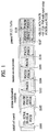
- FIG. 1 is a diagram for explaining physical channels used for 3GPP LTE/LTE-A system and a general signal transmission method using the physical channels.
- the user equipment may perform an initial cell search job for matching synchronization with a base station and the like [S101].
- the user equipment may match synchronization with the base station in a manner of receiving a primary synchronization channel (P-SCH) and a secondary synchronization channel (S-SCH) from the base station and may obtain information such as a cell ID and the like.
- P-SCH primary synchronization channel
- S-SCH secondary synchronization channel
- the user equipment may receive a physical broadcast channel from the base station and may be then able to obtain intra-cell broadcast information.
- the user equipment may receive a downlink reference signal (DL RS) in the initial cell search step and may be then able to check a DL channel state.
- DL RS downlink reference signal
- the user equipment may receive a physical downlink control channel (PDCCH) and a physical downlink shared control channel (PDSCH) according to the physical downlink control channel (PDCCH) and may be then able to obtain detailed system information [S102].
- PDCH physical downlink control channel
- PDSCH physical downlink shared control channel
- the user equipment may be able to perform a random access procedure to complete the access to the base station [S103 to S106].
- the user equipment may transmit a preamble on a physical random access channel (PRACH) [S103] and may be then able to receive a response message via PDCCH and a corresponding PDSCH in response to the preamble [S104].
- PRACH physical random access channel
- it may be able to perform a contention resolution procedure such as a transmission S105 of an additional physical random access channel and a channel reception S106 of a physical downlink control channel and a corresponding physical downlink shared channel.
- the user equipment may be able to perform a PDCCH/PDSCH reception S107 and a PUSCH/PUCCH (physical uplink shared channel/physical uplink control channel) transmission S108 as a general uplink/downlink signal transmission procedure.
- Control information transmitted to a base station by a user equipment may be commonly named uplink control information (hereinafter abbreviated UCI).
- the UCI may include HARQ-ACK/NACK (Hybrid Automatic Repeat and reQuest Acknowledgement/Negative-ACK), SR (Scheduling Request), CSI (channel status information), and the like.
- the CSI includes CQI (Channel Quality Indication), PMI (Precoding Matrix Indication), RI (Rank Indication) information and the like.
- the UCI is normally transmitted via PUCCH by periods. Yet, in case that both control information and traffic data need to be simultaneously transmitted, the UCI may be transmitted on PUSCH. Moreover, the UCI may be non-periodically transmitted in response to a request/indication made by a network.
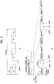
- FIG. 2 is a diagram for an example of a radio frame structure.
- a radio frame include a plurality of subframes and one subframe includes a plurality of OFDMs or SC-FDMA symbols.
- 3GPP LTE (-A) standard supports a type 1 radio frame structure for FDD (frequency division duplex) and a type 2 radio frame structure for TDD (time division duplex).
- FIG. 2 (a) shows an example of a type 1 radio frame structure.
- a downlink radio frame consists of 10 subframes and one subframe consists of 2 slots in time domain.
- a length of a subframe corresponds to 1 ms and a length of one slot may correspond to 0.5 ms.
- One slot includes a plurality of OFDM symbols or a plurality of SC-FDMA symbols in time domain and includes a plurality of resource blocks (RB) in frequency domain.
- 3GPP LTE (-A) system uses OFDMA in DL and SC-FDMA in UL.
- FIG. 2 (b) shows an example of a type 2 radio frame structure.
- a type 2 radio frame consists of 2 half frames. Each of the half frames consists of 4 normal subframes and one special subframe.
- the special subframe consists of a DwPTS (downlink pilot time slot), a GP (guard period) and an UpPTS (uplink pilot time slot).
- the DwPTS is used for initial cell search, synchronization or channel estimation in a user equipment.
- the UpPTS is used for channel estimation in a base station and uplink transmission synchronization of a user equipment.
- the guard period provides switching time between UL transmission and DL transmission.
- Each of the normal subframes is used for UL transmission or DL transmission in a radio frame according to UL-DL configuration (uplink-downlink configuration).
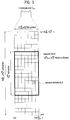
- FIG. 3 is a diagram for an example of a resource grid of a downlink slot.
- a structure of an UL slot is identical to a structure of a DL slot. Yet, an OFDM symbol is replaced with an SC-FDMA symbol.
- one downlink (DL) slot may include a plurality of OFDM symbols in time domain.
- one DL slot exemplarily includes N DL symb (e.g., 6 or 7) OFDM symbols and one resource block (RB) exemplarily includes N RB sc (e.g., 12) subcarriers in frequency domain.
- Each element on a resource grid is called a resource element (RE).
- An RB includes NRB sc ⁇ N DL symb (e.g., 12 ⁇ 7 (6)) REs.
- the number N DL RB of resource blocks may depend on a DL transmission bandwidth.
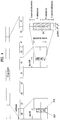
- FIG. 4 to FIG. 6 show examples of a synchronization channel (SCH).
- SCH synchronization channel
- the user equipment acquires DL time synchronization of a base station and base station identification information (e.g., base station ID (identifier), cell ID) by detecting an SCH.
- the user equipment is consistently matched with the DL time synchronization using the SCH even after accessing the network.
- the user equipment can acquire time synchronization of a target base station and base station identification information by detecting an SCH of the target base station.
- an SCH includes a P-SCH (primary synchronization channel) and an S-SCH (secondary synchronization channel).
- the P-SCH is positioned at a last OFDM symbol of a slot # 0 and a slot # 10.
- the P-SCH is transmitted using 72 subcarriers (10 sub-carriers are reserved and a PSS is transmitted on 62 subcarriers) in a corresponding OFDM symbol.
- An identical PSS primary synchronization signal
- a code used for the PSS can be called a PSC (primary synchronization code).
- the P-SCH is used to acquire time domain synchronization including OFDM symbol synchronization, slot synchronization and the like and/or frequency domain synchronization.
- a ZC (Zadoff-Chu) sequence can be used as a PSS.
- the ZC sequence is one of CAZAC (constant amplitude zero auto-correlation) sequences which are orthogonal sequences.
- d 11 k exp ⁇ j ⁇ uk k + 1 N ZC when N ZC is odd number
- d 11 k exp ⁇ j ⁇ uk 2 N ZC when N ZC is even number
- the CAZAC sequence may have three characteristics as follow.
- d k 1 for all k , N ZC , u R u ;
- N ZC m const Equation 2 means that the CAZAC sequence always has a size of 1.
- Equation 3 means that auto correlation of the CAZAC sequence is represented by a Dirac-delta function. The auto correlation is based on circular correlation.
- Equation 4 means that cross correlation is always a constant number.
- a P-SCH is regulated by a ZC sequence of 62-long according to Equation 5 as follows.
- a root index u of the ZC sequence is given in Table 1 as follows. [Table 1] N ID 2 Root index u 0 25 1 29 2 34
- FIG. 5 shows an example of mapping a PSS to a subcarrier.
- a ZC sequence of 63-long (N ZC ) is mapped to 64 subcarriers including a DC subcarrier.
- the ZC sequence is firstly mapped to a subcarrier situating at the very left in order to map a 31 st element P (31) of the ZC sequence to the DC subcarrier.
- a null value is inserted to a subcarrier (32 nd subcarrier) to which a sequence is not mapped in a mapping section.
- the DC subcarrier is punched.
- an S-SCH is positioned at an OFDM symbol immediately before a last OFDM symbol of a slot # 0 and a slot # 10.
- the S-SCH and a P-SCH are positioned at contiguous OFDM symbols.
- the S-SCH is transmitted using 72 subcarriers (10 subcarriers are reserved and an SSS is transmitted on 62 subcarriers) in a corresponding OFDM symbol.
- SSSs secondary synchronization signals
- the S-SCH is used to obtain frame synchronization, cell group ID and/or CP configuration of a cell (i.e., use information of a normal CP or an extended CP).
- SSC secondary synchronization code
- a code combination (m0 and m1), which is mapped to the S-SCH, can be defined as Equation 6 in the following.
- m 0 m ′ mod 31
- m 1 m 0 + ⁇ m ′ / 31 ⁇ + 1 mod 31
- m ′ N ID 1 + q q + 1 / 2
- q ⁇ N ID 1 + q ′ q ′ + 1 / 2 30 ⁇
- q ′ ⁇ N ID 1 / 30 ⁇
- a relation between a cell group ID and the code combination (m0 and m1) can be defined as Table 2 in the following.
- [Table 2] N ID 1 m 0 m 1 N ID 1 m 0 m 1 N ID 1 ID m 0 m 1 N ID 1 ID m 0 m 1 N ID 1 ID m 0 m 1 N ID 1 ID m 0 m 1 0 0 1 34 4 6 68 9 12 102 15 19 136 22 27 1 1 2 35 5 7 69 10 13 103 16 20 137 23 28 2 2 3 36 6 8 70 11 14 104 17 21 138 24 29 3 3 4 37 7 9 71 12 15 105 18 22 139 25 30 4 4 5 38 8 10 72 13 16 106 19 23 140 0 6 5 5 6 39 9 11 73 14 17 107 20 24 141 1 7 6 6 7 40 10 12 74 15 18 108 21 25 142 2 8 7 7 8 41 11 13 75 16 19 109 22 26 143 3 9 8 8 9 42 12 14 76 17 20 110 23
- an order of the m0 and the m1 varies according to a subframe and the order is used to estimate synchronization of a radio frame. For instance, (m0, m1) is transmitted in a (0-) th subframe and (m1, m0) is transmitted in a (10-) th subframe. Meanwhile, if a cell A has a combination of (1, 2) and a cell B has an SSS of a combination of (3, 4), it is possible for a user equipment to incorrectly detect it as a combination of (1, 4) and (3, 2). To prevent this, an SSC can be scrambled by a code one-to-one defined with a PSC.
- a PSC-based scrambling code includes the 31-long m-sequence, which is generated from the multinomial expression x ⁇ 5 + x ⁇ 2 + 1. Six sequences are generated by a circular shift and two sequences correspond to three PSC indexes. Yet, in case that the cell A and the cell B use an identical PSC code, there still exist possibility of misdetection for the SSC. Hence, segment 1-based scrambling can be additionally performed.
- an SSC of a segment 2 can be scrambled by a code corresponding to an index of a segment 1.
- a segment 1-based scrambling code includes a 31-long m-sequence generated from a multinomial expression x ⁇ 5 + x ⁇ 4 + x ⁇ 2 + x ⁇ 1 + 1. Eight sequences are generated by a circular shift and each sequence corresponds to indexes of the segment 1 in a manner of one-to-many.
- n 0 or greater than 0 and the n equals to 30 or less than 30.
- Both m 0 and m 1 are related to a physical cell ID (PCID) group N ID 1 and can be defined by Equation 6 and Table 2.
- a sequence s 0 m 0 n and a sequence s 1 m 1 n can be obtained by a circular shift of an m-sequence s ⁇ ( n ) as depicted in Equation 8 in the following.
- s 0 m 0 n s ⁇ n + m 0 mod 31
- s 1 m 1 n s ⁇ n + m 1 mod 31
- a scrambling sequence c 0 ( n ) and c 1 ( n ) are based on a PSS and can be obtained by a circular shift of an m-sequence c ⁇ ( n ) as depicted in Equation 9 in the following.
- c 0 n c ⁇ n + N ID 2 mod 31
- c 1 n c ⁇ n + N ID 2 + 3 mod 31
- N ID 2 ⁇ 0 1 2 indicates a physical cell ID in a physical cell ID group N ID 1 .
- a scrambling sequence z 1 m 0 n and z 1 m 1 n can be obtained by a circular shift of an m-sequence z ⁇ ( n ) as depicted in Equation 10 in the following.
- z 1 m 0 n z ⁇ n + m 0 mod 8 mod 31
- z 1 m 1 n z ⁇ n + m 1 mod 8 mod 31
- both m 0 and m 1 are identical to what is defined in the above.
- FIG. 7 is a diagram for an example of a heterogeneous network (HetNet) including a macro cell and a micro cell.
- HetNet heterogeneous network
- a heterogeneous network which includes a micro cell of low transmit power existing within a cell coverage of a legacy macro cell in a manner of being overlapped with each other, is under discussion.
- a macro cell can be overlapped with one or more micro cells.
- a service of the macro cell is provided by a macro eNB (Macro eNode B, M eNB).
- M eNB Micro eNode B
- the macro cell and the macro eNB can be used in a manner of being mixed.
- a UE accessed the macro cell can be called a macro UE (Macro UE, MUE).
- the macro UE receives a signal from the macro eNB and transmits a signal to the macro eNB.
- the micro cell can also be called a femto cell or a pico cell.
- a service of the micro cell is provided by a pico eNB (Pico eNode B), a femto eNB (Femto eNode B), a home eNB (Home eNode B, HeNB), a relay node (RN), or the like.
- a pico eNB Pulico eNode B
- a femto eNB Femto eNode B
- a home eNB Home eNode B, HeNB
- RN relay node
- the micro eNB, the micro cell, the pico eNB, the pico cell, the femto eNB, the femto cell, the home eNB, a home cell, the relay node, a relay cell can be used in a manner of being mixed.
- a UE accessed the micro cell can be called a micro UE, a pico UE (PUE), a femto UE (FUE), a home UE (HUE) or the like.
- the micro UE receives a signal from the micro eNB (e.g., femto eNB, pico eNB) and transmits a signal to the micro eNB.
- a DL signal of a HeNB may affect an MUE as interference and a DL signal of an MeNB may affect a HUE as interference.
- a UL signal of the MUE may affect the HeNB and a UL signal of the HUE may affect the MeNB as interference.
- the HeNB performs a service for a specific HUE only and remaining UEs may correspond to a CSG (closed subscriber group) which is not accessible.
- CSG closed subscriber group
- the MUE is located in the vicinity of the HeNB, since the MUE is unable to access the HeNB, a transmission signal of the HeNB may affect the MUE as strong interference. Consequently, the MUE experiences disorder of receiving a signal from the MeNB.
- the HeNB reduces a transmit power or stops transmitting on a specific timing point and the MeNB transmits a signal to the MUE without interference from the HeNB on the timing point.
- This method is effective for interference mitigation in a PSS and an SSS, which are used by a UE to acquire time synchronization.
- a specific sequence which is determined by a cell ID, is repeatedly transmitted in every radio frame in the PSS/SSS.
- FIG. 8 shows an example of operation that the HeNB does not transmit the PSS/SSS of the HeNB in a part of radio frames to protect the PSS/SSS of the MeNB.
- the HeNB repeats an operation of not transmitting the PSS/SSS in a first 10 radio frames and transmitting the PSS/SSS again in a following 10 radio frames.
- This operation may become a considerable help for synchronization of the MUE.
- this operation may become obstacles for synchronization of the HUE.
- a part of the HUE attempts synchronization in a region where the HeNB does not transmits the PSS/SSS.
- the HUE since the part of the HUE is unable to obtain the synchronization of the HeNB, it may perform an inappropriate operation, i.e., searching for a different cell, and the like.
- the HUE may be connected to the MeNB as a result of detecting the PSSS/SSS of the MeNB.
- the MeNB can move the HUE to the HeNB again for a purpose of load distribution and the like.
- the HUE makes an attempt to detect the PSS/SSS of the HeNB again according to a handover process and can be connected to the HeNB when synchronization is acquired by the HeNB. Consequently, the HUE performs an unnecessary handover process.
- service delay from the HeNB, resource waste due to the handover, and the like may occur.
- the present invention proposes a process for a user equipment to efficiently detect a signal of each cell.
- the present invention proposes that a user equipment recognizes PSS/SSS transmission pattern of a HeNB in a process of acquiring synchronization of the HeNB and uses the PSS/SSS transmission pattern.
- the HeNB can repeat an operation of transmitting PSS/SSS for a predetermined time (e.g., T1 number of radio frames) (T1: positive integer) and an operation of not transmitting the PSS/SSS for a following predetermined time (e.g., T2 number of radio frames) (T2: positive integer) and the user equipment can acquire synchronization of the HeNB using the PSS/SSS transmission pattern of the HeNB.
- a value of the T1 may mean a minimum number or a maximum number (preferably, minimum number) of radio frames in which the HeNB PSS/SSS is contiguously transmitted.
- a value of the T2 may mean a minimum number or a maximum number (preferably, maximum number) of radio frames in which the HeNB PSS/SSS is not contiguously transmitted. For instance, if the HeNB begins to transmit the PSS/SSS, PSS/SSS transmission can last for at least T1 number of radio frames. And, the HeNB may be able to not transmit the PSS/SSS for maximum T2 number of radio frames. The PSS/SSS can be transmitted after the T2 number of radio frames are passed by.
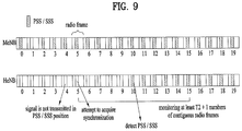
- a user equipment recognizes a HeNB PSS/SSS transmission pattern and may be able to operate as follows. First of all, assume that the user equipment fails to detect a HeNB PSS/SSS on a specific timing point. In this case, instead of judging that a HeNB cell does not exist, the user equipment can assume that HeNB PSS/SSS transmission may previously exist in maximum T2 + a (a is an integer greater than 0, preferably greater than 1) radio frames. Hence, in spite of a failure of detecting the HeNB PSS/SSS, the user equipment can make an attempt to continuously detect the HeNB PSS/SSS for at least T2 + a radio frames. By doing so, the user equipment can avoid a process of searching for a different cell despite of a failure of acquiring synchronization on a specific timing point on which the HeNB PSS/SSS is not transmitted.
- T2 + a is an integer greater than 0, preferably greater than 1
- FIG. 9 is a diagram for an example of a process of acquiring synchronization according to embodiment of the present invention.
- a user equipment e.g., HUE
- FIG. 9 shows a case that the user equipment makes an attempt to detect the HeNB PSS/SSS in an additional radio frame after the T2 number of radio frames are passed by
- a can be variously configured. For instance, after the T2 number of radio frames are passed by, the user equipment can make an attempt to detect the HeNB PSS/SSS for additional maximum T1 number of radio frames.
- a can be configured as follows. 01 ⁇ a ⁇ T1, preferably, 1 ⁇ a ⁇ T1.
- the HeNB causes interference to a MeNB PSS/SSS in a manner of transmitting a PSS/SSS on a specific timing point on which a user equipment (e.g., MUE) intends to acquire synchronization of a MeNB.
- a user equipment e.g., MUE
- the user equipment may fail to detect the MeNB PSS/SSS and acquire synchronization.
- the user equipment can make an attempt to detect the MeNB PSS/SSS in T1 + b (b is an integer greater than 0, preferably greater than 1) number of radio frames.
- the user equipment fails to detect the MeNB PSS/SSS, the user equipment expects that PSS/SSS interference transmitted from the HeNB is disappeared before a predetermined time (e.g., if maximum value of radio frames in which the PSS/SSS is contiguously transmitted by the HeNB corresponds to T1 number of radio frames, T1 number of radio frames) is passed by and can continuously make an attempt to synchronize with the MeNB.
- synchronization with the MeNB can be performed by an operation of consistently reattempting synchronization with the MeNB for a predetermined time (e.g., if minimum value of radio frames in which the PSS/SSS is not contiguously transmitted by the HeNB corresponds to T2 number of radio frames, T2 number of radio frames) after the T1 number of ratio frames and the like.
- whether a user equipment uses an assumption that the PSS/SSS interference is mitigated on a predetermined timing point when MeNB synchronization is attempted in a specific MeNB cell region (among a whole network) and/or various parameters related to the assumption may be delivered to the user equipment from the MeNB and/or HeNB via system information, an RRC (radio resource control) signaling, or the like.
- RRC radio resource control
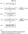
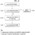
- FIG. 10 to FIG. 11 shows examples of a process of acquiring synchronization according to embodiment of the present invention.
- FIG. 10 shows an example of a process of acquiring synchronization with a HeNB
- FIG. 11 shows an example of a process of acquiring synchronization with a MeNB.
- a user equipment makes an attempt to detect an SCH of HeNB to acquire synchronization [S1002].
- the SCH may be differently called or configured.
- the SCH includes a P-SCH and an S-SCH.
- the SCH includes a PA-preamble (primary advanced preamble) and an SA-preamble (secondary advanced preamble). If the HeNB SCH is successfully detected [S1004], the user equipment acquires DL synchronization of the HeNB and may be then able to recognize a PCID of the HeNB from the DL synchronization [S1006a].
- the user equipment can make an attempt to detect the HeNB SCH while continuously monitoring the HeNB SCH for T2 + a radio frames [S1006b].
- the user equipment assumes that there may exist HeNB SCH transmission within at least T2 + a radio frames instead of assuming that there is no HeNB.
- MeNB SCH detection attempt may be restricted in the monitoring process.
- the T2 may mean the (maximum) number of radio frames in which the HeNB SCH is not contiguously transmitted.
- 'a' is an integer equals to 0 or greater than 0, preferably, an integer equals to 1 or greater than 1.
- An upper limit of the 'a' can be limited to a T1.
- the T1 may means the (minimum) number of radio frames in which the HeNB SCH is contiguously transmitted. Acquisition of the T1 and/or the T2 shall be described in detail later.
- the user equipment acquires DL synchronization of the HeNB and may be then able to recognize a PCID of the HeNB from the DL synchronization [S1010a].
- the user equipment assumes that there is no HeNB and may be then able to make an attempt to detect an SCH of a different base station (e.g., MeNB) [S1010b].
- a different base station e.g., MeNB
- the process of FIG. 10 may be restricted to be performed only for a case that the user equipment knows existence of the HeNB in advance (via a neighbor cell list and the like) or a case that the user equipment is signaled to perform the operation of FIG. 10 .
- This sort of information can be delivered to the user equipment via system information or an upper layer signaling (e.g., RRC signaling).
- the process of FIG. 10 can be performed for a case that the user equipment accesses the HeNB rather than the MeNB. In this case, detection attempt for the MeNB can be restricted except the S1010b step.
- a user equipment makes an attempt to detect an SCH of MeNB to acquire synchronization [S1102]. If the MeNB SCH is successfully detected [S1104], the user equipment acquires DL synchronization of the MeNB and may be then able to recognize a PCID of the MeNB from the DL synchronization [S1106a]. Meanwhile, if the user equipment fails to detect the MeNB SCH [S1104], the user equipment can make an attempt to detect the MeNB SCH while continuously monitoring the MeNB SCH for T1 + b radio frames [S1106b].
- the user equipment if the user equipment fails to detect the MeNB SCH, the user equipment assumes that the failure of the MeNB SCH detection is caused by interference of a difference cell (e.g., HeNB) and the interference from the different cell is mitigated within at least T1 + b radio frames.
- HeNB SCH detection attempt may be restricted in the monitoring process.
- the T1 may mean the (minimum) number of radio frames in which the HeNB SCH is contiguously transmitted.
- 'b' is an integer equals to 0 or greater than 0, preferably, an integer equals to 1 or greater than 1.
- An upper limit of the 'b' can be limited to a T2.
- the T2 may means the (maximum) number of radio frames in which the HeNB SCH is not contiguously transmitted. Acquisition of the T1 and/or the T2 shall be described in detail later.
- the user equipment Via the monitoring process according to the step S1106b, the user equipment detects the SCH of the MeNB, acquires DL synchronization of the MeNB, and may be then able to recognize a PCID of the HeNB from the DL synchronization [S1108].
- the user equipment should recognize a value of the T1 and/or the T2.
- the MeNB and/or the HeNB can inform the user equipment of information on at least one of a cell ID, a cell ID used for a micro cell (e.g., CSG cell), whether a non-contiguous PSS/SSS signal transmission pattern is used, the value of the T1 and/or the T2 via system information, a dedicated RRC (radio resource control) signal, and the like.
- a dedicated RRC radio resource control
- the T1 and/or the T2 may be automatically set to a corresponding value.
- the user equipment recognizes the T1 and/or the T2 although there is no separate signaling and may be able to perform a process of acquiring base station synchronization. For instance, since a PSS/SSS sequence is determined by a corresponding cell ID (refer to FIG. 4 to FIG.
- a HUE performs synchronization with a base station (e.g., HeNB) including a specific cell ID
- the HUE can perform the proposed operations in a manner of assuming the value of the T1 and/or the T2 determined by the corresponding cell ID.
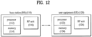
- FIG. 12 is a diagram for an example of a base station and a user equipment to which embodiment of the present invention is applicable.
- a wireless communication system includes a base station (BS) 110 and a user equipment (UE) 120.
- the BS includes a processor 112, a memory 114, and a radio frequency (RF) unit 116.
- the processor 112 can be configured to implement procedure and/or methods proposed by the present invention.
- the memory 114 is connected with the processor 112 and stores various informations related to the operation of the processor 112.
- the RF unit 116 is connected with the processor 112 and transceive a radio signal.
- the UE 120 includes a processor 122, a memory 124, and a radio frequency (RF) unit 126.
- the processor 122 can be configured to implement procedure and/or methods proposed by the present invention.
- the memory 124 is connected with the processor 122 and stores various informations related to the operation of the processor 122.
- the RF unit 126 is connected with the processor 122 and transceive a radio signal.
- the BS 110 and/or the UE 120 may have a single antenna or multiple antennas.
- a specific operation explained as performed by a base station can be occasionally performed by an upper node of the base station.
- various operations performed for communication with a user equipment can be performed by a base station or other networks except the base station.
- 'base station' can be replaced by such a terminology as a fixed station, a Node B, an eNode B (eNB), an access point, and the like.
- eNB eNode B
- 'user equipment' can be replaced by such a terminology as a user equipment (UE), a mobile station (MS), a mobile subscriber station (MSS) and the like.
- Embodiments of the present invention can be implemented using various means. For instance, embodiments of the present invention can be implemented using hardware, firmware, software and/or any combinations thereof. In case of the implementation by hardware, a method according to each embodiment of the present invention can be implemented by at least one selected from the group consisting of ASICs (application specific integrated circuits), DSPs (digital signal processors), DSPDs (digital signal processing devices), PLDs (programmable logic devices), FPGAs (field programmable gate arrays), processor, controller, microcontroller, microprocessor and the like.
- ASICs application specific integrated circuits
- DSPs digital signal processors
- DSPDs digital signal processing devices
- PLDs programmable logic devices
- FPGAs field programmable gate arrays
- processor controller, microcontroller, microprocessor and the like.
- a method according to each embodiment of the present invention can be implemented by modules, procedures, and/or functions for performing the above-explained functions or operations.
- Software code is stored in a memory unit and is then drivable by a processor.
- the memory unit is provided within or outside the processor to exchange data with the processor through the means well-known to the public.
- the present invention can be used by such a wireless communication device as a user equipment, a relay, a base station, and the like.
Landscapes
- Engineering & Computer Science (AREA)
- Computer Networks & Wireless Communication (AREA)
- Signal Processing (AREA)
- Mobile Radio Communication Systems (AREA)
Claims (12)
- Procédé d'acquisition de synchronisation temporelle dans un système de communication sans fil, le procédé comprenant :l'obtention d'informations sur une configuration de transmission non contiguë d'un canal de synchronisation ;la détection (S1002, S1102) d'un canal de synchronisation d'une station de base (110) ; et .la re-détection (S1006b, S1106b) du canal de synchronisation de la station de base (110) pendant un temps prédéterminé si le processus de détection échoue,dans lequel si la station de base (110) correspond à un premier type, le temps prédéterminé est égal ou supérieur à une durée pendant laquelle un canal de synchronisation n'est pas transmis de manière contiguë dans la configuration de transmission non contiguë, etdans lequel si la station de base (110) correspond à un second type, le temps prédéterminé est égal ou supérieur à une durée pendant laquelle un canal de synchronisation est transmis de manière contiguë dans la configuration de transmission non contiguë.
- Procédé selon la revendication 1, dans lequel si la station de base correspond au premier type, le temps prédéterminé est fixé à une durée maximum pendant laquelle un canal de synchronisation n'est pas transmis de manière contiguë dans la configuration de transmission non contiguë de manière à être égal à la durée maximum ou supérieur à la durée maximum.
- Procédé selon la revendication 1, dans lequel si la station de base correspond au second type, le temps prédéterminé est fixé à une durée minimum pendant laquelle un canal de synchronisation est transmis de manière contiguë dans la configuration de transmission non contiguë de manière à être égal à la durée minimum ou supérieur à la durée minimum.
- Procédé selon la revendication 1, dans lequel la configuration de transmission non contiguë du canal de synchronisation est définie pour le premier type de station de base.
- Procédé selon la revendication 4, dans lequel le premier type de station de base comprend une station de base domestique, et dans lequel le second type de station de base comprend une macro station de base.
- Procédé selon la revendication 1, dans lequel les informations sur la configuration de transmission non contiguë du canal de synchronisation sont prédéterminées en fonction d'un identifiant de cellule.
- Dispositif de communication (120) configuré pour acquérir une synchronisation temporelle dans un système de communication sans fil, comprenant :une unité de fréquence radio, RF (126) ; etun processeur (112),le processeur (112) est configuré pour obtenir des informations sur une configuration de transmission non contiguë d'un canal de synchronisation, en vue de détecter un canal de synchronisation d'une station de base (110) ; et pour redétecter le canal de synchronisation de la station de base (110) pendant un temps prédéterminé si le processus de détection échoue,dans lequel si la station de base (110) correspond à un premier type, le temps prédéterminé est égal ou supérieur à une durée pendant laquelle un canal de synchronisation n'est pas transmis de manière contiguë dans la configuration de transmission non contiguë, etdans lequel si la station de base (110) correspond à un second type, le temps prédéterminé est égal ou supérieur à une durée pendant laquelle un canal de synchronisation est transmis de manière contiguë dans la configuration de transmission non contiguë.
- Dispositif de communication (120) selon la revendication 7, dans lequel si la station de base (110) correspond au premier type, le temps prédéterminé est fixé à une durée maximum pendant laquelle un canal de synchronisation n'est pas transmis de manière contiguë dans la configuration de transmission non contiguë de manière à être égal à la durée maximum ou supérieur à la durée maximum.
- Dispositif de communication (120) selon la revendication 7, dans lequel si la station de base (110) correspond au second type, le temps prédéterminé est fixé à une durée minimum pendant laquelle un canal de synchronisation est transmis de manière contiguë dans la configuration de transmission non contiguë de manière à être égal à la durée minimum ou supérieur à la durée minimum.
- Dispositif de communication (120) selon la revendication 7, dans lequel la configuration de transmission non contiguë du canal de synchronisation est définie pour le premier type de station de base.
- Dispositif de communication (120) selon la revendication 10, dans lequel le premier type de station de base comprend une station de base domestique et dans lequel le second type de station de base comprend une macro station de base.
- Dispositif de communication (120) selon la revendication 7, dans lequel les informations sur la configuration de transmission non contiguë du canal de synchronisation sont prédéterminées en fonction d'un identifiant de cellule.
Applications Claiming Priority (3)
| Application Number | Priority Date | Filing Date | Title |
|---|---|---|---|
| US201161510044P | 2011-07-20 | 2011-07-20 | |
| US201161522225P | 2011-08-10 | 2011-08-10 | |
| PCT/KR2012/005819 WO2013012286A2 (fr) | 2011-07-20 | 2012-07-20 | Procédé d'acquisition de synchronisation temporelle dans des réseaux hétérogènes et appareil pour ledit procédé |
Publications (3)
| Publication Number | Publication Date |
|---|---|
| EP2736292A2 EP2736292A2 (fr) | 2014-05-28 |
| EP2736292A4 EP2736292A4 (fr) | 2015-04-22 |
| EP2736292B1 true EP2736292B1 (fr) | 2016-07-20 |
Family
ID=47558637
Family Applications (1)
| Application Number | Title | Priority Date | Filing Date |
|---|---|---|---|
| EP12815065.3A Not-in-force EP2736292B1 (fr) | 2011-07-20 | 2012-07-20 | Procédé d'acquisition de synchronisation temporelle dans des réseaux hétérogènes et appareil pour ledit procédé |
Country Status (4)
| Country | Link |
|---|---|
| US (1) | US9144043B2 (fr) |
| EP (1) | EP2736292B1 (fr) |
| KR (1) | KR101520713B1 (fr) |
| WO (1) | WO2013012286A2 (fr) |
Families Citing this family (3)
| Publication number | Priority date | Publication date | Assignee | Title |
|---|---|---|---|---|
| US9078146B2 (en) * | 2012-09-10 | 2015-07-07 | Qualcomm Incorporated | Secondary synchronization signal (SSS) post-processing to eliminate short code collision induced false cells |
| US10206188B2 (en) * | 2015-01-08 | 2019-02-12 | Electronics And Telecommunications Research Institute | Method and apparatus for transmitting synchronization signal in mobile communication system |
| US10701647B2 (en) | 2017-03-24 | 2020-06-30 | Electronics And Telecommunications Research Institute | Operation method of communication node transmitting synchronization signal in communication network |
Family Cites Families (11)
| Publication number | Priority date | Publication date | Assignee | Title |
|---|---|---|---|---|
| JPH10290194A (ja) * | 1997-04-15 | 1998-10-27 | Toshiba Corp | 移動通信方法および装置 |
| KR100575710B1 (ko) * | 2002-07-20 | 2006-05-03 | 엘지전자 주식회사 | 업링크 동기 검출방법 |
| JP2004064451A (ja) * | 2002-07-29 | 2004-02-26 | Nec Corp | 回線復旧方法及び移動通信システム |
| WO2009054058A1 (fr) * | 2007-10-25 | 2009-04-30 | Fujitsu Limited | Procédé de transmission, station de base sans fil et station mobile |
| KR101375936B1 (ko) * | 2008-02-01 | 2014-03-18 | 엘지전자 주식회사 | 시간동기 타이머의 만료 시 하향링크 harq의 동작 방법 |
| US20090247157A1 (en) * | 2008-03-28 | 2009-10-01 | Qualcomm Incorporated | Femto cell system selection |
| US8626223B2 (en) * | 2008-05-07 | 2014-01-07 | At&T Mobility Ii Llc | Femto cell signaling gating |
| KR20100131304A (ko) * | 2009-06-05 | 2010-12-15 | 삼성전자주식회사 | 무선통신시스템에서 인접 기지국 정보를 확인하기 위한 장치 및 방법 |
| US8670432B2 (en) | 2009-06-22 | 2014-03-11 | Qualcomm Incorporated | Methods and apparatus for coordination of sending reference signals from multiple cells |
| US8520633B2 (en) * | 2010-07-23 | 2013-08-27 | Clearwire Ip Holdings Llc | Method and system for synchronizing wireless devices with a communication network |
| TWI461080B (zh) * | 2012-05-15 | 2014-11-11 | Inst Information Industry | 網路站台功率調整裝置及其功率調整方法 |
-
2012
- 2012-07-20 WO PCT/KR2012/005819 patent/WO2013012286A2/fr not_active Ceased
- 2012-07-20 KR KR1020147000483A patent/KR101520713B1/ko not_active Expired - Fee Related
- 2012-07-20 EP EP12815065.3A patent/EP2736292B1/fr not_active Not-in-force
- 2012-07-20 US US14/131,888 patent/US9144043B2/en not_active Expired - Fee Related
Also Published As
| Publication number | Publication date |
|---|---|
| KR101520713B1 (ko) | 2015-05-18 |
| EP2736292A2 (fr) | 2014-05-28 |
| US20140140337A1 (en) | 2014-05-22 |
| KR20140037200A (ko) | 2014-03-26 |
| EP2736292A4 (fr) | 2015-04-22 |
| WO2013012286A2 (fr) | 2013-01-24 |
| WO2013012286A3 (fr) | 2013-03-21 |
| US9144043B2 (en) | 2015-09-22 |
Similar Documents
| Publication | Publication Date | Title |
|---|---|---|
| US11856541B2 (en) | Method for transmitting synchronization reference signal for device-to-device (D2D) communication in wireless communication system and apparatus therefor | |
| EP3499994B1 (fr) | Procédé permettant à un terminal de transmettre des données à un autre terminal dans un système de communication sans fil | |
| AU2020286305B2 (en) | Extended synchronization signal for symbol index detection | |
| KR102058999B1 (ko) | 무선 통신 시스템에서 초기 접속 방법 및 장치 | |
| US8964684B2 (en) | Method and apparatus for providing control information | |
| EP3157189B1 (fr) | Procédé et appareil de transmission et de réception de signal d'un terminal de dispositif à dispositif dans un système de communications sans fil | |
| US10110428B2 (en) | Method and apparatus for configuring frame of unlicensed band | |
| CN111670563B (zh) | 在无线通信系统中发送/接收无线信号的方法和装置 | |
| EP2887739B1 (fr) | Procédé et appareil pour effectuer un transfert intercellulaire dans un système de communication sans fil | |
| US9398496B2 (en) | Method and apparatus for performing handover in wireless communication system | |
| KR20120139102A (ko) | 다중 요소 반송파 시스템에서 제어채널의 수신장치 및 방법 | |
| EP2759175B1 (fr) | Procédé et appareil permettant d'obtenir une synchronisation dans un système de radiocommunication | |
| US10321500B2 (en) | Method and apparatus for transmitting/receiving signal by device-to-device UE in wireless communication system | |
| EP2736292B1 (fr) | Procédé d'acquisition de synchronisation temporelle dans des réseaux hétérogènes et appareil pour ledit procédé | |
| KR102546637B1 (ko) | 비면허대역 프레임 구성 방법 및 장치 | |
| US20250254675A1 (en) | Methods and apparatuses for sidelink beam management |
Legal Events
| Date | Code | Title | Description |
|---|---|---|---|
| PUAI | Public reference made under article 153(3) epc to a published international application that has entered the european phase |
Free format text: ORIGINAL CODE: 0009012 |
|
| 17P | Request for examination filed |
Effective date: 20140124 |
|
| AK | Designated contracting states |
Kind code of ref document: A2 Designated state(s): AL AT BE BG CH CY CZ DE DK EE ES FI FR GB GR HR HU IE IS IT LI LT LU LV MC MK MT NL NO PL PT RO RS SE SI SK SM TR |
|
| DAX | Request for extension of the european patent (deleted) | ||
| A4 | Supplementary search report drawn up and despatched |
Effective date: 20150323 |
|
| RIC1 | Information provided on ipc code assigned before grant |
Ipc: H04W 56/00 20090101AFI20150317BHEP |
|
| GRAP | Despatch of communication of intention to grant a patent |
Free format text: ORIGINAL CODE: EPIDOSNIGR1 |
|
| INTG | Intention to grant announced |
Effective date: 20160215 |
|
| GRAS | Grant fee paid |
Free format text: ORIGINAL CODE: EPIDOSNIGR3 |
|
| GRAA | (expected) grant |
Free format text: ORIGINAL CODE: 0009210 |
|
| AK | Designated contracting states |
Kind code of ref document: B1 Designated state(s): AL AT BE BG CH CY CZ DE DK EE ES FI FR GB GR HR HU IE IS IT LI LT LU LV MC MK MT NL NO PL PT RO RS SE SI SK SM TR |
|
| REG | Reference to a national code |
Ref country code: GB Ref legal event code: FG4D |
|
| REG | Reference to a national code |
Ref country code: CH Ref legal event code: EP |
|
| REG | Reference to a national code |
Ref country code: IE Ref legal event code: FG4D |
|
| REG | Reference to a national code |
Ref country code: AT Ref legal event code: REF Ref document number: 814959 Country of ref document: AT Kind code of ref document: T Effective date: 20160815 |
|
| REG | Reference to a national code |
Ref country code: DE Ref legal event code: R096 Ref document number: 602012020827 Country of ref document: DE |
|
| REG | Reference to a national code |
Ref country code: NL Ref legal event code: FP |
|
| REG | Reference to a national code |
Ref country code: SE Ref legal event code: TRGR |
|
| REG | Reference to a national code |
Ref country code: LT Ref legal event code: MG4D |
|
| REG | Reference to a national code |
Ref country code: AT Ref legal event code: MK05 Ref document number: 814959 Country of ref document: AT Kind code of ref document: T Effective date: 20160720 |
|
| PG25 | Lapsed in a contracting state [announced via postgrant information from national office to epo] |
Ref country code: BE Free format text: LAPSE BECAUSE OF NON-PAYMENT OF DUE FEES Effective date: 20160731 |
|
| PG25 | Lapsed in a contracting state [announced via postgrant information from national office to epo] |
Ref country code: NO Free format text: LAPSE BECAUSE OF FAILURE TO SUBMIT A TRANSLATION OF THE DESCRIPTION OR TO PAY THE FEE WITHIN THE PRESCRIBED TIME-LIMIT Effective date: 20161020 Ref country code: FI Free format text: LAPSE BECAUSE OF FAILURE TO SUBMIT A TRANSLATION OF THE DESCRIPTION OR TO PAY THE FEE WITHIN THE PRESCRIBED TIME-LIMIT Effective date: 20160720 Ref country code: RS Free format text: LAPSE BECAUSE OF FAILURE TO SUBMIT A TRANSLATION OF THE DESCRIPTION OR TO PAY THE FEE WITHIN THE PRESCRIBED TIME-LIMIT Effective date: 20160720 Ref country code: HR Free format text: LAPSE BECAUSE OF FAILURE TO SUBMIT A TRANSLATION OF THE DESCRIPTION OR TO PAY THE FEE WITHIN THE PRESCRIBED TIME-LIMIT Effective date: 20160720 Ref country code: IS Free format text: LAPSE BECAUSE OF FAILURE TO SUBMIT A TRANSLATION OF THE DESCRIPTION OR TO PAY THE FEE WITHIN THE PRESCRIBED TIME-LIMIT Effective date: 20161120 Ref country code: IT Free format text: LAPSE BECAUSE OF FAILURE TO SUBMIT A TRANSLATION OF THE DESCRIPTION OR TO PAY THE FEE WITHIN THE PRESCRIBED TIME-LIMIT Effective date: 20160720 Ref country code: LT Free format text: LAPSE BECAUSE OF FAILURE TO SUBMIT A TRANSLATION OF THE DESCRIPTION OR TO PAY THE FEE WITHIN THE PRESCRIBED TIME-LIMIT Effective date: 20160720 |
|
| PG25 | Lapsed in a contracting state [announced via postgrant information from national office to epo] |
Ref country code: PT Free format text: LAPSE BECAUSE OF FAILURE TO SUBMIT A TRANSLATION OF THE DESCRIPTION OR TO PAY THE FEE WITHIN THE PRESCRIBED TIME-LIMIT Effective date: 20161121 Ref country code: GR Free format text: LAPSE BECAUSE OF FAILURE TO SUBMIT A TRANSLATION OF THE DESCRIPTION OR TO PAY THE FEE WITHIN THE PRESCRIBED TIME-LIMIT Effective date: 20161021 Ref country code: PL Free format text: LAPSE BECAUSE OF FAILURE TO SUBMIT A TRANSLATION OF THE DESCRIPTION OR TO PAY THE FEE WITHIN THE PRESCRIBED TIME-LIMIT Effective date: 20160720 Ref country code: ES Free format text: LAPSE BECAUSE OF FAILURE TO SUBMIT A TRANSLATION OF THE DESCRIPTION OR TO PAY THE FEE WITHIN THE PRESCRIBED TIME-LIMIT Effective date: 20160720 Ref country code: BE Free format text: LAPSE BECAUSE OF FAILURE TO SUBMIT A TRANSLATION OF THE DESCRIPTION OR TO PAY THE FEE WITHIN THE PRESCRIBED TIME-LIMIT Effective date: 20160720 Ref country code: AT Free format text: LAPSE BECAUSE OF FAILURE TO SUBMIT A TRANSLATION OF THE DESCRIPTION OR TO PAY THE FEE WITHIN THE PRESCRIBED TIME-LIMIT Effective date: 20160720 Ref country code: LV Free format text: LAPSE BECAUSE OF FAILURE TO SUBMIT A TRANSLATION OF THE DESCRIPTION OR TO PAY THE FEE WITHIN THE PRESCRIBED TIME-LIMIT Effective date: 20160720 |
|
| REG | Reference to a national code |
Ref country code: CH Ref legal event code: PL |
|
| REG | Reference to a national code |
Ref country code: DE Ref legal event code: R097 Ref document number: 602012020827 Country of ref document: DE |
|
| PG25 | Lapsed in a contracting state [announced via postgrant information from national office to epo] |
Ref country code: MC Free format text: LAPSE BECAUSE OF FAILURE TO SUBMIT A TRANSLATION OF THE DESCRIPTION OR TO PAY THE FEE WITHIN THE PRESCRIBED TIME-LIMIT Effective date: 20160720 Ref country code: RO Free format text: LAPSE BECAUSE OF FAILURE TO SUBMIT A TRANSLATION OF THE DESCRIPTION OR TO PAY THE FEE WITHIN THE PRESCRIBED TIME-LIMIT Effective date: 20160720 Ref country code: EE Free format text: LAPSE BECAUSE OF FAILURE TO SUBMIT A TRANSLATION OF THE DESCRIPTION OR TO PAY THE FEE WITHIN THE PRESCRIBED TIME-LIMIT Effective date: 20160720 Ref country code: LI Free format text: LAPSE BECAUSE OF NON-PAYMENT OF DUE FEES Effective date: 20160731 Ref country code: CH Free format text: LAPSE BECAUSE OF NON-PAYMENT OF DUE FEES Effective date: 20160731 |
|
| REG | Reference to a national code |
Ref country code: IE Ref legal event code: MM4A |
|
| PLBE | No opposition filed within time limit |
Free format text: ORIGINAL CODE: 0009261 |
|
| STAA | Information on the status of an ep patent application or granted ep patent |
Free format text: STATUS: NO OPPOSITION FILED WITHIN TIME LIMIT |
|
| PG25 | Lapsed in a contracting state [announced via postgrant information from national office to epo] |
Ref country code: CZ Free format text: LAPSE BECAUSE OF FAILURE TO SUBMIT A TRANSLATION OF THE DESCRIPTION OR TO PAY THE FEE WITHIN THE PRESCRIBED TIME-LIMIT Effective date: 20160720 Ref country code: DK Free format text: LAPSE BECAUSE OF FAILURE TO SUBMIT A TRANSLATION OF THE DESCRIPTION OR TO PAY THE FEE WITHIN THE PRESCRIBED TIME-LIMIT Effective date: 20160720 Ref country code: BG Free format text: LAPSE BECAUSE OF FAILURE TO SUBMIT A TRANSLATION OF THE DESCRIPTION OR TO PAY THE FEE WITHIN THE PRESCRIBED TIME-LIMIT Effective date: 20161020 Ref country code: SK Free format text: LAPSE BECAUSE OF FAILURE TO SUBMIT A TRANSLATION OF THE DESCRIPTION OR TO PAY THE FEE WITHIN THE PRESCRIBED TIME-LIMIT Effective date: 20160720 Ref country code: SM Free format text: LAPSE BECAUSE OF FAILURE TO SUBMIT A TRANSLATION OF THE DESCRIPTION OR TO PAY THE FEE WITHIN THE PRESCRIBED TIME-LIMIT Effective date: 20160720 |
|
| REG | Reference to a national code |
Ref country code: FR Ref legal event code: ST Effective date: 20170503 |
|
| 26N | No opposition filed |
Effective date: 20170421 |
|
| GBPC | Gb: european patent ceased through non-payment of renewal fee |
Effective date: 20161020 |
|
| PG25 | Lapsed in a contracting state [announced via postgrant information from national office to epo] |
Ref country code: FR Free format text: LAPSE BECAUSE OF NON-PAYMENT OF DUE FEES Effective date: 20160920 Ref country code: IE Free format text: LAPSE BECAUSE OF NON-PAYMENT OF DUE FEES Effective date: 20160720 Ref country code: GB Free format text: LAPSE BECAUSE OF NON-PAYMENT OF DUE FEES Effective date: 20161020 |
|
| PG25 | Lapsed in a contracting state [announced via postgrant information from national office to epo] |
Ref country code: LU Free format text: LAPSE BECAUSE OF NON-PAYMENT OF DUE FEES Effective date: 20160720 Ref country code: SI Free format text: LAPSE BECAUSE OF FAILURE TO SUBMIT A TRANSLATION OF THE DESCRIPTION OR TO PAY THE FEE WITHIN THE PRESCRIBED TIME-LIMIT Effective date: 20160720 |
|
| PG25 | Lapsed in a contracting state [announced via postgrant information from national office to epo] |
Ref country code: HU Free format text: LAPSE BECAUSE OF FAILURE TO SUBMIT A TRANSLATION OF THE DESCRIPTION OR TO PAY THE FEE WITHIN THE PRESCRIBED TIME-LIMIT; INVALID AB INITIO Effective date: 20120720 Ref country code: CY Free format text: LAPSE BECAUSE OF FAILURE TO SUBMIT A TRANSLATION OF THE DESCRIPTION OR TO PAY THE FEE WITHIN THE PRESCRIBED TIME-LIMIT Effective date: 20160720 |
|
| PG25 | Lapsed in a contracting state [announced via postgrant information from national office to epo] |
Ref country code: MT Free format text: LAPSE BECAUSE OF NON-PAYMENT OF DUE FEES Effective date: 20160731 Ref country code: MK Free format text: LAPSE BECAUSE OF FAILURE TO SUBMIT A TRANSLATION OF THE DESCRIPTION OR TO PAY THE FEE WITHIN THE PRESCRIBED TIME-LIMIT Effective date: 20160720 |
|
| PG25 | Lapsed in a contracting state [announced via postgrant information from national office to epo] |
Ref country code: AL Free format text: LAPSE BECAUSE OF FAILURE TO SUBMIT A TRANSLATION OF THE DESCRIPTION OR TO PAY THE FEE WITHIN THE PRESCRIBED TIME-LIMIT Effective date: 20160720 Ref country code: TR Free format text: LAPSE BECAUSE OF FAILURE TO SUBMIT A TRANSLATION OF THE DESCRIPTION OR TO PAY THE FEE WITHIN THE PRESCRIBED TIME-LIMIT Effective date: 20160720 |
|
| PGFP | Annual fee paid to national office [announced via postgrant information from national office to epo] |
Ref country code: SE Payment date: 20200608 Year of fee payment: 9 Ref country code: NL Payment date: 20200608 Year of fee payment: 9 |
|
| PGFP | Annual fee paid to national office [announced via postgrant information from national office to epo] |
Ref country code: DE Payment date: 20200605 Year of fee payment: 9 |
|
| REG | Reference to a national code |
Ref country code: DE Ref legal event code: R119 Ref document number: 602012020827 Country of ref document: DE |
|
| REG | Reference to a national code |
Ref country code: NL Ref legal event code: MM Effective date: 20210801 |
|
| PG25 | Lapsed in a contracting state [announced via postgrant information from national office to epo] |
Ref country code: DE Free format text: LAPSE BECAUSE OF NON-PAYMENT OF DUE FEES Effective date: 20220201 |
|
| PG25 | Lapsed in a contracting state [announced via postgrant information from national office to epo] |
Ref country code: SE Free format text: LAPSE BECAUSE OF NON-PAYMENT OF DUE FEES Effective date: 20210721 Ref country code: NL Free format text: LAPSE BECAUSE OF NON-PAYMENT OF DUE FEES Effective date: 20210801 |