EP2736300B1 - Procédé de commutation de canal dans un système de communication sans fil et appareil pour ledit procédé - Google Patents
Procédé de commutation de canal dans un système de communication sans fil et appareil pour ledit procédé Download PDFInfo
- Publication number
- EP2736300B1 EP2736300B1 EP12814579.4A EP12814579A EP2736300B1 EP 2736300 B1 EP2736300 B1 EP 2736300B1 EP 12814579 A EP12814579 A EP 12814579A EP 2736300 B1 EP2736300 B1 EP 2736300B1
- Authority
- EP
- European Patent Office
- Prior art keywords
- channel
- channel switching
- coordinator
- field
- frequency band
- Prior art date
- Legal status (The legal status is an assumption and is not a legal conclusion. Google has not performed a legal analysis and makes no representation as to the accuracy of the status listed.)
- Not-in-force
Links
- 238000000034 method Methods 0.000 title claims description 57
- 238000004891 communication Methods 0.000 title description 29
- 230000000737 periodic effect Effects 0.000 claims description 5
- 230000006870 function Effects 0.000 description 27
- 230000005540 biological transmission Effects 0.000 description 25
- 230000004044 response Effects 0.000 description 11
- 238000007726 management method Methods 0.000 description 8
- 238000005516 engineering process Methods 0.000 description 7
- 230000001149 cognitive effect Effects 0.000 description 4
- 230000008569 process Effects 0.000 description 4
- 230000008859 change Effects 0.000 description 3
- 230000000694 effects Effects 0.000 description 3
- 238000012545 processing Methods 0.000 description 3
- 230000036541 health Effects 0.000 description 2
- 230000010363 phase shift Effects 0.000 description 2
- 241000760358 Enodes Species 0.000 description 1
- 235000008694 Humulus lupulus Nutrition 0.000 description 1
- 108700026140 MAC combination Proteins 0.000 description 1
- 230000002730 additional effect Effects 0.000 description 1
- 238000003491 array Methods 0.000 description 1
- 230000015572 biosynthetic process Effects 0.000 description 1
- 238000004364 calculation method Methods 0.000 description 1
- 230000001419 dependent effect Effects 0.000 description 1
- 230000007774 longterm Effects 0.000 description 1
- 230000007246 mechanism Effects 0.000 description 1
- 238000010295 mobile communication Methods 0.000 description 1
- 238000012986 modification Methods 0.000 description 1
- 230000004048 modification Effects 0.000 description 1
- 238000012544 monitoring process Methods 0.000 description 1
- 230000006855 networking Effects 0.000 description 1
- 238000004088 simulation Methods 0.000 description 1
- 230000001360 synchronised effect Effects 0.000 description 1
- 238000012795 verification Methods 0.000 description 1
Images


Classifications
-
- H—ELECTRICITY
- H04—ELECTRIC COMMUNICATION TECHNIQUE
- H04W—WIRELESS COMMUNICATION NETWORKS
- H04W52/00—Power management, e.g. Transmission Power Control [TPC] or power classes
- H04W52/02—Power saving arrangements
-
- H—ELECTRICITY
- H04—ELECTRIC COMMUNICATION TECHNIQUE
- H04W—WIRELESS COMMUNICATION NETWORKS
- H04W72/00—Local resource management
- H04W72/04—Wireless resource allocation
- H04W72/044—Wireless resource allocation based on the type of the allocated resource
- H04W72/0453—Resources in frequency domain, e.g. a carrier in FDMA
-
- H—ELECTRICITY
- H04—ELECTRIC COMMUNICATION TECHNIQUE
- H04W—WIRELESS COMMUNICATION NETWORKS
- H04W4/00—Services specially adapted for wireless communication networks; Facilities therefor
- H04W4/80—Services using short range communication, e.g. near-field communication [NFC], radio-frequency identification [RFID] or low energy communication
-
- H—ELECTRICITY
- H04—ELECTRIC COMMUNICATION TECHNIQUE
- H04W—WIRELESS COMMUNICATION NETWORKS
- H04W72/00—Local resource management
- H04W72/20—Control channels or signalling for resource management
-
- H—ELECTRICITY
- H04—ELECTRIC COMMUNICATION TECHNIQUE
- H04W—WIRELESS COMMUNICATION NETWORKS
- H04W84/00—Network topologies
- H04W84/18—Self-organising networks, e.g. ad-hoc networks or sensor networks
- H04W84/20—Leader-follower arrangements
Definitions
- the present invention relates to a wireless communication system and, more particularly, to a method for switching channels in which a device is operated in a WPAN (Wireless Personal Area Network) system and an apparatus supporting the same.
- WPAN Wireless Personal Area Network
- LR-WPAN Low-Rate Wireless Personal Area Networks
- An example of the LR-WPAN may include a network following the IEEE 802.15.4 standard.
- the IEEE 802.15.4 standard uses BPSK (binary phase-shift keying) in a 868/915 MHz band, so as to provide a transmission rate of 20Kbps and 40Kbps, and the IEEE 802.15.4 standard uses O-QPSK (offset quadrature phase-shift keying) in a 2.45 GHz band, so as to provide a transmission rate of 250Kbps.
- the IEEE 802.15.4b standard may also use O-QPSK in an 868/915 MHz band, so as to provide a transmission rate of 250Kbps.
- an MBAN Medical Body Area Network
- the MBAN system operates in a 2360 ⁇ 2400 MHz band based upon an IEEE 802.15.4j, and a maximum emission bandwidth is limited to 5 MHz.
- a transmission power of the MBAN system may correspond to a lower value of 1mW and 10*log(B) dBm.
- B corresponds to a 20dB emission bandwidth.
- B corresponds to a 20dB emission bandwidth.
- the MBAN system is operated based upon a cognitive radio technology.
- the cognitive radio technology refers to a communication technology allowing a network or wireless communication device to actively detect and determine its surrounding communication environment, so as to adaptively change transmission/reception characteristics, such as a frequency band for an optimal communication, transmission power, encoding method, and so on.
- the device prioritizes its operation by using a method that does not interfere with (or interrupt) the communication of the corresponding users.
- the MBAN devices are operated inside of a registered health care facility.
- the operation of the devices should be stopped, or transmission should be performed by changing the transmission band to the 2390 ⁇ 2400 MHz band, which is used as the basic band.
- the usage of 2360 ⁇ 2390 MHz should be limited in accordance with a cooperation between the licensed users, and, when other licensed users use the corresponding based, all operations in this band should be initialized, and the operations should be resumed by newly using the 2390 ⁇ 2400 MHz band.
- the operations may be resumed by performing channel switch to another channel within the 2360 ⁇ 2390 MHz band instead of the 2390 ⁇ 2400 MHz band.
- the MBAN devices may be used without limitation both inside and outside of the facility.
- US 2005/128982 discloses an access point, which may preemptively broadcast an alternate channel to switch to, along with an indication of the beacon timing for the alternate channel, prior to any catastrophic interference.
- the access point may switch to the alternate channel in the event of interference on the original channel without attempting to broadcast the alternate channel during the interference event.
- a mobile user may then know in advance of the interference event which alternate channel the access point switched to and may switch to the alternate channel.
- Multi-dimensional channel management scheme to avoid beacon collision in LR-WPAN proposes a dynamic channel management scheme using MDS (multi-dimensional scheduling).
- MDS multi-dimensional scheduling
- PAN coordinator that uses MDS is more than that of PC that use IEEE 802.15.4.
- XP068041204 "Final proposal for 802.15.4j MBANS” by LG (ppt) and XP068041206, "Final proposal for IEEE 802.15.4j MBAN” by LG (doc) propose MAC enhancement for MBANs by channel switch notification and Periodic GTS.
- An object of the present invention is to propose a method for easily transmitting and receiving data between a coordinator and a device in a wireless communication system, and, preferably, in a WPAN (Wireless Personal Area Network) system and a device for the same.
- WPAN Wireless Personal Area Network
- an object of the present invention is to propose a method for easily switching an operating channel of a device without having to perform a scanning operation on all channels of a channel band to which the device is switched and a device for the same.
- an object of the present invention is to propose a method for more efficiently using radio resources and a device for the same.
- a channel switching method in a method for switching an operating channel of a device in a WPAN (Wireless Personal Area Network) system, a channel switching method is defined in independent claim 1.
- the device in another aspect of the present invention, in a device switching an operating channel of a device in a WPAN (Wireless Personal Area Network) system, the device is defined in independent claim 4.
- WPAN Wireless Personal Area Network
- data may be easily transmitted and received between a coordinator and a device in a wireless communication system, and, preferably, in a WPAN system.
- an operating channel of a device may be easily switched without having to perform a scanning operation on all channels of a channel band to which the device is switched.
- radio resources may be more efficiently used.
- the specification of the present invention mainly describes the exemplary embodiments of the present invention based upon the data-transmission and data-reception relation between a base station and a terminal.
- the base station has its significance as a terminal node of a network directly performing communication with the terminal.
- specific operations described to be performed by the base station may also be, in some occasion, performed by an upper node of the base station. More specifically, it will be apparent that, in a network configured of multiple network nodes, a variety of operations performed in the network in order to communicate with the terminal may be performed by the base station or by other network nodes that do not belong to the base station.
- BS Base Station
- eNB eNode B
- AP Access Point
- PAN coordinator Personal Area Network coordinator
- MBAN coordinator Medical Body Area Network coordinator
- PAN MBAN coordinator PAN MBAN coordinator
- the term 'Terminal' may be replaced with other terms, such as UE (User Equipment), MS (Mobile Station), MSS (Mobile Subscriber Station), SS (Subscriber Station), AMS (Advanced Mobile Station), MTC (Machine-Type Communication) device, M2M (Machine-to-Machine) device, D2D (Device-to-Device) device, a FFD (Full Function Device), an RFD (Reduced Function Device), and so on.
- UE User Equipment
- MS Mobile Station
- MSS Mobile Subscriber Station
- SS Subscriber Station
- AMS Advanced Mobile Station
- MTC Machine-Type Communication
- M2M Machine-to-Machine
- D2D Device-to-Device
- FFD Full Function Device
- RFD Reduced Function Device
- the exemplary embodiments of the present invention may be supported by the standard documents that are disclosed in at least any one of the diverse wireless access systems, such as an IEEE 802 system, a 3GPP system, 3GPP LTE and LTE-A (LTE-Advanced) systems, and a 3GPP2 system. More specifically, among the exemplary embodiments of the present invention, the description of obvious process steps or elements of the present invention that have not been described herein may be supported by the above-mentioned documents. Furthermore, all of the terms mentioned in the description of the present invention may be described and defined with reference to the standard documents.
- CDMA Code Division Multiple Access
- FDMA Frequency Division Multiple Access
- TDMA Time Division Multiple Access
- OFDMA Orthogonal Frequency Division Multiple Access
- SC-FDMA Single Carrier Frequency Division Multiple Access
- the CDMA may be realized by a radio technology such as UTRA (Universal Terrestrial Radio Access) or CDMA2000.
- the TDMA may be realized by a radio technology such as GSM (Global System for Mobile communications)/GPRS (General Packet Radio Service)/EDGE (Enhanced Data Rates for GSM Evolution).
- GSM Global System for Mobile communications
- GPRS General Packet Radio Service
- EDGE Enhanced Data Rates for GSM Evolution
- the OFDMA may be realized by a radio technology such as IEEE 802.11 (Wi-Fi), IEEE 802.15, IEEE 802.16 (WiMAX), IEEE 802-20, E-UTRA (Evolved UTRA), and so on.
- the UTRA corresponds to a portion of the UMTS (Universal Mobile Telecommunications System).
- the 3GPP (3rd Generation Partnership Project) LTE (long term evolution) system adopts the OFDMA in a downlink and adopts the SC-FDMA in an uplink.
- the LTE-A LTE-Advanced
- LTE-A LTE-Advanced
- Fig. 1 illustrates a Network Topology according to an IEEE 802.15.4 system.
- FFD Full Function Device
- RFD Reduced Function Device
- the topology of the network according to the IEEE 802.15.4 system may be decided based upon the functions of the devices participating in the corresponding network.
- the FFD corresponds to a device that can perform all functions, e.g ., the FFD may perform communication with an FFD or RFD, and the FFD may also other functions, such as network initialization, node management, node information storage, and so on.
- a PAN coordinator an FFD operating so that other devices can configure a network.
- the PAN coordinator may also be referred to as an MBAN coordinator, a PAN MBAN coordinator, and so on.
- the PAN coordinator will be collectively referred to as a 'coordinator'. Accordingly, the above-described network topology may be configured based upon the FFD, which performs the function of the coordinator.
- the RFD performs a fewer number of functions as compared to the number of functions that can be performed by the FDD.
- counterpart devices that can communicate with the RFD are only limited to FFDs. Therefore, the RFD cannot perform the functions of the coordinator.
- the RFD may have a stack structure of a smaller size, thereby being capable of saving operation (or calculation)/memory resources.
- the RFD can locate a coordinator and transmit data thereto and then immediately disconnect itself so as to enter a Power Saving mode (or Sleep mode), the amount of consumed power may be very small, and, therefore, the RFD may be operated for a long period of time with the power of its battery.
- a device being indicated as "F” represents the FFD
- a device being indicated as "R” represents the RFD
- a device being indicated as "P” represents an FFD performing the roles of a coordinator.
- the devices may correspond to a starting point or an ending point of the communication
- the coordinator may correspond to a starting point, an ending point, or a router.
- the communication between the device and the coordinator is performed in accordance with at least one or more hops using intermediate devices (or middle devices), which function as relays.
- each device may perform communication with any one of the devices existing in the network. Therefore, a network having a more complicated structure, such as a mesh network, may be configured.
- the coordinator functions as an access point to upper (or higher-level) layers, and, in case of a Wireless Sensor Network (WSN), the coordinator functions as a sync for data being collected by sensors.
- WSN Wireless Sensor Network
- the star network may operate the devices so that the durability of the battery may be maintained for a long period of time, and, since the Peer to Peer network may configure at least one or more data delivery paths, the Peer to Peer network may have higher data reliability and higher access recognition rate.
- the star topology has an extremely limited communication range respective to each device ( e.g ., several meters), and the peer-to-peer topology allows a larger area to be covered. Since a topology can be dynamic (or mobile), the topology varies when devices are added or leave the network.
- the star topology may be appropriate for a situation, wherein the coordinator exchanges a signal with devices respective to one patient.
- the peer-to-peer topology may correspond to a more appropriate topology, wherein one coordinator is being provided to serve multiple patients (e.g ., the coordinator may be located at a fixed position within the hospital).
- the coordinator may either be mobile or stationary.
- the peer-to-peer topology may be more appropriate for a quickly changing environment, which requires the network to be quickly set up or changed, or which requires self-organization and self-healing of the network to be allowed.
- self-healing may include establishing a new coordinator, when an already-existing coordinator is out of order or has left the network.
- Each device has its own coordinator
- a same location such as a hospital.
- individual coordinators may cooperate in order to avoid interference with one another and to allow sharing or collation of data.
- such network is referred to as a 'cluster', and a provision for dividing and combining clusters may be realized.
- Fig. 2 illustrates a protocol stack of the IEEE 802.15.4 system.
- the protocol stack may consist of a PHY layer (Physical layer), a MAC layer (Medium Access Control layer), and an Upper layer.
- the PHY layer includes an RF transceiver (or transmitter/receiver) and a related control mechanism.
- the PHY layer may provide a PHY data service transceiving (or transmitting/receiving) PHY PDUs (Protocol Data Units) through a physical channel and a PHY management service for managing the PHY layer.
- PHY data service transceiving or transmitting/receiving
- PHY PDUs Protocol Data Units
- the MAC layer provides access to a physical channel for data transmission.
- the MAC layer may provide a MAC data service transceiving (or transmitting/receiving) MAC PDUs (Protocol Data Units) through a physical channel and a MAC management service for performing MAC layer management.
- the MAC layer may perform functions, such as beacon management, channel access, GTS management, frame verification, security functions, and so on.
- the Upper Layer is configured of a Network Layer and an Application Layer.
- the network layer provides functions, such as network configuration, processing, message routing, and so on.
- the application layer provides the functions targeted by the device. For example, depending upon the type of the program installed therein. i.e ., depending upon the type of the program processing the data of the application layer, a device of the IEEE 802.15.4 system may perform as an RFD (Reduced Function Device), an FFD (Full Function Device), or a coordinator.
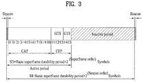
- Fig. 3 illustrates a superframe structure of the IEEE 802.15.4 system.
- the IEEE 802.15.4 system may be divided into a beacon-enabled operation, wherein the network is operated based upon a beacon that is periodically broadcasted, and a non beacon-enabled operation, wherein the network is operated by non-periodically requesting for a beacon in order to perform communication frame exchange.
- the coordinator periodically transmits a beacon, and the devices periodically listens to (or receives) the beacon in order to be synchronized to the network and to access channels.
- channel access is sequentially transmitted in frame units within a superframe in accordance with a superframe structure, which is defined by the coordinator.
- the superframe may be configured to have a structure including a plurality of time slots (e.g ., 16 time slots) in order to transceive (transmit and receive) data between beacon frames being transmitted by the coordinator. Additionally, each superframe may be configured to include an active period and an inactive period due to a requirement for low-power operation between the beacon frames.
- the active period corresponds to a period, wherein data transception is performed between the devices, and the active period is configured of time slots for frames being used to perform data transception.
- the inactive period refers to a period, wherein data transception is not performed between the devices. More specifically, during the inactive period, the coordinator may enter a low-power mode (or sleep mode).
- a ratio between the active period and the inactive period may be referred to as a duty cycle, and the value of the duty cycle may be adjusted based upon requirements for the low-power operation and also based upon requirements for the co-existence of communication methods using the same physical transmission (or transport) channel.
- the active period may be configured to include a Contention Access Period (CAP) and a Contention Free Period (CFP), which follows the CAP for an ensured access of applications having service quality requirements.
- CAP Contention Access Period
- CCP Contention Free Period
- the CAP is configured of time slots enabling devices participating in a network to perform contention-based transmission of data frames. Therefore, in case of a device that intends to perform communication by using time slots belonging to the CAP, which is located between the two beacon frames, the corresponding device is in a contention-based relation with another device by using the CSMA-CA (Carrier Sense Multiple Access/Collision Avoidance) method.
- CSMA-CA Carrier Sense Multiple Access/Collision Avoidance
- the CFP is configured of GTSs (Guaranteed Time Slots), which correspond to time slots being allocated (or assigned) to allow a specific device to transmit data frames.
- GTS may be used for a low-latency application program (or application program having a fast response speed) or for an application program requiring a specific transmission bandwidth within the device.
- the CFP is located after the CAP within the superframe, and the CFP may be configured to include up to a maximum limit of 7 GTSs. Additionally, the CFP may also be configured to have multiple GTS to be assigned (or allocated) to a single device.
- the coordinator decides to which device each GTS within the CFP is to be allocated (or assigned).
- the GTS allocation information of the CFP which is decided by the coordinator, may be transmitted while being included in a beacon frame, which corresponds to the very first slot of the superframe.
- the coordinator does not transmit a beacon for synchronization.
- Channel access is not limited only to a superframe structure, and, since the devices are asynchronous, all data transmission is performed by CSMA-CA. This may allow devices, which do not have data to be transmitted, to be maintained in the Sleep mode for most of the time, and by having the coordinator place a wake-up preamble in front of each data frame, the coordinator may follow its own sleep pattern in accordance with a predetermined protocol, such as a sensor-MAC (WiseMAC), which ensures the receiving device to be active when data reach the device.
- a sensor-MAC Wi-MAC
- the coordinator within the beacon-enabled network performs the function of providing synchronization and channel access to the network devices. Additionally, a starting point and ending point of a superframe is defined by the coordinator.
- the coordinator has two characteristics, one being potential communication with other networks, and the other being, for example, access to sufficient power supply due to an easy replacement of a charged battery.
- Fig. 4 illustrates an example of each frame format within a MAC layer and a PHY layer in the IEEE 802.15.4 system.
- the frame format in a MAC layer consists of a MAC header (MHR), a MAC payload, and a MAC footer (MFR).
- MHR MAC header
- MFR MAC footer
- the MHR, MAC payload, and MFR configure one MAC data frame, i.e., one MAC protocol data unit (MPDU).
- MPDU MAC protocol data unit
- the MHR includes a Frame Control field (401), a Sequence Number field (403), an Addressing Field (405), and an Auxiliary Security Header field (407).
- the Frame Control field (401) includes a value indicating a frame format type (or kind)
- the Sequence Number field (403) includes a current value of a macDSN
- the Addressing Field (405) may include a receiving and/or transmitting address.
- the Auxiliary Security Header field (407) may include information required for performing security processing of the frame.
- the MAC payload may be configured to include a Command Frame Identifier and a Command Payload.
- the MFR may be configured to include a Frame Check Sequence (FCS) (411).
- FCS Frame Check Sequence
- the FCS (411) may be used to determine whether or not an error occurs in data transmission respective to the MHR and MAC payload portions.
- the IEEE 802.15.4 network accompanies four different types of frames, such as a beacon frame being used by the coordinator in order to transmit a beacon, a data frame being used in order to transmit data, an acknowledgement frame being used in order to verify a successful frame reception, and a MAC command frame being used in order to handle all types of MAC peer entity control transmission, such as a data request.
- a beacon frame being used by the coordinator in order to transmit a beacon
- a data frame being used in order to transmit data
- an acknowledgement frame being used in order to verify a successful frame reception
- a MAC command frame being used in order to handle all types of MAC peer entity control transmission, such as a data request.
- each of the beacon frame, the acknowledgement frame, and the MAC command frame has a different MAC payload
- the acknowledgement frame does not have a MAC payload
- the beacon frame, the acknowledgement frame, and the MAC command frame have similar structures.
- the beacon frame, the acknowledgement frame, and the MAC command frame may
- the MPDU is transmitted to a PHY layer as a PHY Service Data Unit (PSDU), and this becomes a PHY payload within the PHY layer.
- the preamble sequence (413) and the data SFD (415) enable the receiver to achieve symbol synchronization.
- Such SHR, PHR, and PHY payload configure one PHY packet, i.e., a PHY protocol data unit (PPDU).
- PPDU PHY protocol data unit
- Fig. 5 illustrates an example of a beacon frame format of the IEEE 802.15.4 system.
- the beacon frame includes an MHR, a MAC payload, and an MFR.
- the MHR includes a Frame Control field (501), a Sequence Number field (503), an Addressing Field (505), and an Auxiliary Security Header field (507).
- the MAC payload of the beacon frame may include a Superframe specification field (509), GTS fields (511), Pending Address fields (513), and a Beacon Payload field (515).
- the MFR may be configured to include a frame check sequence (FCS) (517).
- FCS frame check sequence
- the Superframe specification field (509) may include information on beacon order, superframe order, a last CAP slot, a CAP, a CFP, an active period length, battery durability, whether or not transmission is performed by the coordinator, and so on.
- the diverse information mentioned above is merely exemplary, and, therefore, the information being included in the Superframe specification field (509) may be varied.
- the GTS fields (411) may include a GTS specification field, a GTS Direction field, and a GTS List field.
- the Superframe specification field may include a GTS descriptor count subfield.
- the GTS descriptor count subfield indicates a number of GTS descriptors that are to be included in the GTS List field. For example, in case the size of the GTS descriptor count subfield is equal to 3 bits, the GTS List field may include a maximum of 7 GTS descriptors.
- the GTS Direction field may include a GTS Directions Mask subfield, which indicates the direction of GTSs within the subframe.
- the GTS Directions Mask subfield may respectively indicate whether each GTS corresponds to a data transmit-only GTS or a data receive-only GTS.
- the GTS List field may include a GTS descriptor field indicating GTS allocation information.
- the GTS List field may include one or more GTS descriptor fields in accordance with a value indicated by the GTS descriptor count subfield. Additionally, whether each GTS descriptor field is being used for transmitting data or for receiving data may be decided by the GTS Directions Mask subfield.
- each GTS descriptor field may be configured to include a Device Short Address field, a GTS Starting Slot field, a GTS Length field, a Start Sequence Number field, a GTS Interval field, and a GTS Window field.
- the Device Short Address field indicates the address of devices having the GTS allocated thereto by the GTS descriptor. More specifically, in case a GTS associated with the GTS descriptor field is allocated to the device, the Device Short Address field is assigned with the address of the device.
- the GTS Starting Slot field indicates information on a Superframe slot in which the GTS starts.
- the GTS Length field indicates a number of GTSs that are contiguously (or serially) activated within the superframe.
- the GTS Interval field indicates a value designating a number of superframes after which the GTS is to be allocated.
- the GTS Interval field may be assigned with a value indicating the superframe interval at which the GTS is allocated or may be assigned with a value of a specific time at which the GTS is allocated.
- the GTS Window field indicates a value indicating a range within which the GTS can be allocated before and after the superframe, which is designated by the GTS Interval field.
- Fig. 6 illustrates a channel alignment of the IEEE 802.15.4 system.
- the IEEE 802.15.4 system operating in a 2400 MHz band has a channel spacing interval of 5 MHz.
- An MBAN system based upon the IEEE 802.15.4 system uses a 2360 ⁇ 2390 MHz band and a 2390 ⁇ 2400 MHz band.
- the 2360 ⁇ 2390 MHz band may be used when the MBAN device is allocated with a channel from an MBAN coordinator and operated accordingly within a healthcare facility.
- the 2390 ⁇ 2400 MHz band may be used when the MBAN device can no longer receive any information on a MBAN channel from the MBAN coordinator, or when the MBAN device and coordinator are operated outside of the healthcare facility.
- the 2390 ⁇ 2400 MHz band may also be used as a basic channel band of the MBAN system.
- Fig. 7 illustrates an exemplary MBAN system channel alignment.
- Fig. 7 shows available channels of the MBAN within the 2360 ⁇ 2400 MHz band.
- the MBAN device operating in the 2360 ⁇ 2400 MHz band may occasionally be required to change the operating channel from a channel of the 2360 ⁇ 2390 MHz band to a channel of the 2390 ⁇ 2400 MHz band, or vice versa.
- the device of the MBAN system is required to perform operating channel switching to a channel of the 2390 ⁇ 2400 MHz band.
- the device of the MBAN system performs operation defaulting and then performs channel switching.
- the present invention relates to a wireless communication system and, more particularly, to a procedure for transmitting channel switching parameters in an MBAN system and a related frame.
- the MBAN system when the MBAN system has channel switched from a 30 MHz band to a 10 MHz band, it is not preferable to continue to use the channel of the 10 MHz band, since such usage may cause a considerable amount of load to the 10 MHz band. Therefore, it is preferable to channel switch back to the 30 MHz band after a predetermined period of time.
- a channel scanning process is required to be repeatedly performed with respect to all channels at constant time intervals.
- the present invention proposes a method for reducing power consumption by allowing required information to be exchanged between the coordinator and the device in advance during the channel switching procedure, which will be described below, thereby removing unnecessary operations.
- the coordinator may transmit channel switching information to the device.
- the channel switching information informed by the coordinator to the device may be configured of the following Channel switching parameter field.
- Fig. 8 illustrates an example of a channel switching parameter field according to an exemplary embodiment of the present invention.
- the channel switching parameter field may include a Remain Time field (801), a Recommend Channel field (803), and a TBTT (Target Beacon Transmission Time) field (805).
- the Recommend Channel field may be configured of information indicating a channel number of another frequency band to which channel switching is performed (e.g ., Channel Number field) or information indicating a channel page ( e.g ., Channel Page field).
- the Recommend Channel field may further include identifier information of a PAN existing in a channel to which the device has shifted via channel switching (e.g ., PAN identifier (PAN ID) field) or coordinator address information for establishing association in the corresponding channel band (e.g ., Coordinator Address field).
- the Coordinator Address refers to address information of a coordinator operating in a channel, which is specified by the above-described Recommend Channel field (or Channel Number field and Channel Page field), and the identifier of the PAN refers to a PAN identifier of such coordinator.
- the coordinator address may be indicated by any one of a short address of the coordinator or an extended address of the coordinator. Additionally, the coordinator that is currently associated with a device may be aware of which coordinator the corresponding device was associated with prior to the channel switching.
- Each of the fields shown in Fig. 8 is merely an exemplary field included in the channel switching information.
- the channel switching information may be configured to include at least any one of the fields shown in Fig. 8 . Additionally, the order of each field or the size of each field configuring the channel switching information may be changed.
- the Remain Time field (801) refers to a time remaining for the device to shift (or switch) from a 30 MHz band to a 10 MHz band or from a 10 MHz band to a 30 MHz band.
- the Remain Time field (801) may calculate a time period starting from a point when the device has shifted (or switched) from a 30 MHz band to a 10 MHz band or from a 10 MHz band to a 30 MHz band, and the Remain Time field (801) may also calculate a time period starting from a point when the corresponding channel switching parameter field has been transmitted to the device.
- the Remain Time field (801) may be indicated in units of seconds, minutes, hours, or a number of frames or superframes, and so on.
- the Recommend Channel field (803) refers to a channel that is to be shifted (or switched) from a 30 MHz band to a 10 MHz band or from a 10 MHz band to a 30 MHz band and operated accordingly. At this point, the Recommend Channel field (803) may refer to a specific channel. However, the Recommend Channel field (803) may also refer to a channel set including at least any one of the one or more channels.
- the coordinator that is currently associated with a device may be aware of the operating channel of the device in the 30 MHz band or the 10 MHz band prior to being channel switched to the current operating channel band.
- the TBTT field (805) notifies a prearranged transmission time of a beacon frame within an operating channel to which the device is shifted. More specifically, the TBTT field (805) refers to a prearranged transmission time of a beacon frame in an operating channel, which is designated by the Recommend Channel field (803). The device uses the TBTT field (805), which is received from the coordinator, so as to receive a beacon frame at a decided time in order to establish association with a coordinator of the channel, which is switched via channel switching. At this point, the TBTT field (805) may further include information on a cycle period according to which the beacon frame is being transmitted from the switched channel.
- the TBTT field (805) may refers to a specific time scheduled (or prearranged) to have a beacon frame transmitted from a channel, which is being switched by channel switching.
- a prearranged time at which the beacon frame is to be transmitted may be indicated in units of specific hours, minutes, and seconds, and the prearranged time may also be indicated as an index of a specific superframe or frame.
- the TBTT field (805) may calculate a time period starting from a time point at which the remaining time is ended. More specifically, the TBTT field (805) may refer to a time interval starting from the time point, at which the remaining time is ended, up to the transmission of a first beacon frame generating from the channel band to which the device switches via channel switching. Additionally, the TBTT field (805) may also calculate a time period starting from a time point at which the corresponding channel switching parameter field is transmitted to the device. More specifically, the TBTT field (805) may refer to a time interval starting from the time point, at which the channel switching parameter field is transmitted to the device, up to the transmission of a first beacon frame generating from the channel band to which the device switches via channel switching.
- the TBTT field (805) may be indicated in units of seconds, minutes, hours, or a number of frames or superframes, and so on.
- the channel switching information may be transmitted to the device by using a broadcast, multicast, or unicast method.
- the broadcast method may be performed as a transmission method including the channel switching information in the beacon frame.
- the unicast method may be performed by separately defining a command or frame for channel switching.
- the separately defined command or frame may be referred to as a Channel switch notification command, a Channel switching parameter response frame, and so on.
- the device that has received the channel switching information may perform channel switching to a recommended channel after a remaining time. Then, after being operated in the sleep mode, the device wakes up at a TBTT time period and receives a beacon, thereby establishing an association with a coordinator of the corresponding channel.
- Fig. 9 illustrates a channel switching procedure according to an exemplary embodiment of the present invention.
- the 2360 ⁇ 2390 MHz band of the MBAN system corresponds to a first frequency band
- the 2390 ⁇ 2400 MHz band of the MBAN system corresponds to a second frequency band
- the present invention will not be limited only to this.
- the first frequency band may correspond to the 2390 ⁇ 2400 MHz band
- the second frequency band may correspond to the 2360 ⁇ 2390 MHz band.
- a first coordinator and the device establish association between one another through any one channel among the first frequency band channels (S901). Having established association with the first coordinator, the device may transceive (transmit and receive) data with the first coordinator.
- a case when the device, which is transceiving data with the first coordinator, is required to switch the current operating channel to a channel of another frequency band may occur.
- the device switches to a channel of the 2390 ⁇ 2400 MHz band and shall transceiver (transmit and receive) data with the coordinator of the switched channel, i.e., the second coordinator.
- information notifying channel status of each frequency band i.e., information notifying which channels of the 2360 ⁇ 2390 MHz band and the 2390 ⁇ 2400 MHz band of the MBAN can be used and when such channels can be used, may be collected and managed by a controller controlling multiple coordinators.
- the controller may be configured to include a DB (Data Base) storing and managing channel status of each frequency band and an MBAN control point managing the DB.
- DB Data Base
- information related to the usage of each channel of the second frequency band in order to allow the device to channel switch and transceive (transmit and receive) data is delivered from the controller to the first coordinator.
- the device receives the information related to channel switching to the second frequency band from the first coordinator and performs channel switching based upon the received channel switching information (S903).
- the channel switching information may include a channel number of the second frequency band to which the device is to switch, a time at which switching is to be performed, a coordinator identifier of the second frequency band to which switching is to be performed.
- the device establishes association with a second coordinator (S905). After establishing association with the second coordinator, the device may transceive (transmit and receive) data with the second coordinator.
- the device performs channel switching from the first frequency band to the second frequency band, since a continued usage of the channel of the second frequency band may cause a load to the second frequency band, it will be preferable to switch back to the first frequency band after a predetermined period of time. Additionally, a situation where channel switching is required to be performed from the second frequency band back to the first frequency band may occur, such as a case when the usage of the primary user of the first frequency band is ended. In case of a situation where such channel switching is possible, information related to the usage of each channel of the initial frequency band (first frequency band) may be delivered to the second coordinator from the controller.
- the second coordinator After receiving the channel information of the first frequency band from the controller, the second coordinator transmits information related to the channel switching to the device based upon the received channel information (S907). At this point, the second coordinator may transmit the channel switching information to the device by using a broadcast, multicast, or unicast method, and since the description of the channel switching information is identical to the description provided above (2.1.), a detailed description of the same will be omitted.
- the second coordinator in order to transmit the channel switching information to the device, the second coordinator may use a beacon frame, which is periodically broadcasted in step S907.
- Fig. 10 illustrates an example of a beacon frame according to an exemplary embodiment of the present invention.
- a beacon frame may be generated from the second coordinator, which has received information related to the switching to the first frequency band from the MBAN controller, the MBAN control point, and so on.
- the beacon frame may include a channel switching parameter field according to Fig. 8 . More specifically, the beacon frame may include at least any one of a Remain Time field (1013), a Recommend Channel field (1015), and a TBTT field (1017) respective to the beacon transmission time from a channel of the first frequency band.
- the Recommend Channel field may be configured of a Channel Number field and a Channel Page field.
- the second coordinator may include an address field (1011) of a device requiring channel switching in the beacon frame and may transmit the processed beacon frame.
- identifier information of the corresponding device may be included in the address filed (1011) in order to specify the device requiring channel switching.
- identifier information respective to one or more devices may be included in the address field (1011), and, for example, an identifier respective to a group in order to collectively specify devices, which are grouped in accordance with a specific condition, may also be included in the address field (1011).
- the beacon frame may further include a Coordinator Address field of a coordinator operating in a channel of the first frequency band, to which the device has shifted by performing channel switching, or a PAN identifier (PAN ID) of the corresponding coordinator.
- PAN ID PAN identifier
- This is to enable the device to perform active scanning, so as to be capable of swiftly performing a procedure for establishing association with a coordinator existing in the channel of the first frequency band. More specifically, if multiple coordinators exist in the first frequency band, or if a coordinator having an unknown address (or identifier) exists in the first frequency band, the device may swiftly perform channel switching by using the received coordinator address information. At this point, the coordinator address (or identifier), which is included in the channel switching information, may be decided based upon an estimated movement status of the device, an alignment of neighboring coordinators, and so on.
- the device performs channel switching based upon the received channel switching information (S909). More specifically, the device performs channel switching to a recommended channel after the remaining time based upon the channel switching information.
- the device After performing channel switching, the device establishes (or sets up) an association within the first coordinator based upon the channel switching information (S911). More specifically, after being operated in the sleep mode, the device that has performed channel switching wakes up at a TBTT time period and receives a beacon, so as to establish an association with a coordinator operating in the corresponding channel. After establishing the association with the first coordinator, the device may hereinafter transceive (transmit and receive) data with the first coordinator.
- the device is no longer required to periodically perform scanning on all channels in order to find the initial network within the first frequency band.
- power consumption of the device may be reduced, and radio resources may be used more efficiently.
- Fig. 11 illustrates a channel switching procedure according to an exemplary embodiment of the present invention.
- the 2360 ⁇ 2390 MHz band of the MBAN system corresponds to a first frequency band
- the 2390 ⁇ 2400 MHz band of the MBAN system corresponds to a second frequency band
- the present invention will not be limited only to this.
- the first frequency band may correspond to the 2390 ⁇ 2400 MHz band
- the second frequency band may correspond to the 2360 ⁇ 2390 MHz band.
- the device After performing channel switching from the first frequency band to the second frequency band, the device requests for channel switching information to the second coordinator (S1107). Even if the channel switching information is transmitted through the beacon frame, if the cycle period according to which the beacon frame is being transmitted is excessively long, or if the user equipment fails to receive the channel switching information being transmitted through the beacon frame, and so on, the device may request for information related to channel switching to the second coordinator.
- the device may additionally request for channel switching information during the process of establishing association with the second coordinator, which belongs to the second frequency band. And, after completing the process of establishing association, the device may request for the channel switching information.
- the device may request for the channel switching information to the second coordinator.
- the device may use a channel switching parameter request frame in step S1107.
- Fig. 12 illustrates an example of a channel switching parameter request frame according to an exemplary embodiment of the present invention.
- the channel switching parameter request frame may include a Frame Control field (1201), a Sequence Number field (1203), an Addressing Field (1205), and a Command Frame Identifier field (1207), and a Frame Check Sequence (FCS) (1209).
- a Frame Control field (1201)
- a Sequence Number field (1203)
- an Addressing Field (1205)
- a Command Frame Identifier field (1207)
- FCS Frame Check Sequence
- the frame type of the channel switching parameter request frame may correspond to a MAC command frame type, and the device may define the command frame identifier field (1207) to have a predetermined value, so as to indicate that the corresponding field is a message requesting for the channel switching information by the user equipment. For example, among the values of the command frame identifier field (1207), by using a reserved value '0x0a', this may indicate that the command frame identifier field (1207) corresponds to a message requesting for the channel switching information.
- the second coordinator that has received the request for the channel switching information transmits the channel switching information to the device (S1109).
- the second coordinator may transmit the channel switching information to the device by using a broadcast, multicast, or unicast method, and since the description of the channel switching information is identical to the description provided above (2.1.), a detailed description of the same will be omitted.
- the second coordinator may use a channel switching parameter response frame in step S1109.
- Fig. 13 illustrates an example of a channel switching parameter response frame according to an exemplary embodiment of the present invention.
- the channel switching parameter response frame may include a Frame Control field (1301), a Sequence Number field (1303), an Addressing Field (1305), an Auxiliary Security Header field (1307), a Frame Payload field (1317), and a Frame Check Sequence (FCS) (1319). Additionally, the channel switching parameter response frame may include a channel switching parameter field according to Fig. 8 . More specifically, the channel switching parameter response frame may include at least any one of a Remain Time field (1309), a Recommend Channel field (1311), and a TBTT field (1313) respective to the beacon transmission time from a channel of the first frequency band. At this point, the Recommend Channel field may be configured of a Channel Number field and a Channel Page field.
- the channel switching parameter response frame may further include a Coordinator Address field (1315) of a coordinator operating in a channel of the first frequency band, to which the device has shifted by performing channel switching.
- the channel switching parameter response frame may further include, or a PAN identifier (PAN ID) of the coordinator, which is indicated by the coordinator address field (1315). This is to enable the device to perform active scanning, so as to be capable of swiftly performing a procedure for establishing association with a coordinator existing in the channel of the first frequency band.
- PAN ID PAN identifier
- the device may swiftly perform channel switching by using the received coordinator address information.
- the coordinator address (or identifier) which is included in the channel switching information, may be decided based upon an estimated movement status of the device, an alignment of neighboring coordinators, and so on.
- the frame type of the channel switching parameter request frame may correspond to a MAC command frame type, and the device may define the command frame identifier field to have a predetermined value, so as to indicate that the corresponding field is a message requesting for the channel switching information by the user equipment. For example, among the values of the command frame identifier field, by using a reserved value '0x0b', this may indicate that the command frame identifier field corresponds to a message responding to the request for the channel switching information.
- the device performs channel switching based upon the received channel switching information (S1111). More specifically, the device performs channel switching to a recommended channel after the remaining time based upon the channel switching information.
- the device After performing channel switching, the device establishes (or sets up) an association within the first coordinator based upon the channel switching information (S1113). More specifically, after being operated in the sleep mode, the device that has performed channel switching wakes up at a TBTT time period and receives a beacon, so as to establish an association with a coordinator operating in the corresponding channel. After establishing the association with the first coordinator, the device may hereinafter transceive (transmit and receive) data with the first coordinator.
- the device is no longer required to periodically perform scanning on all channels in order to find the initial network within the first frequency band.
- power consumption of the device may be reduced, and radio resources may be used more efficiently.
- Fig. 14 illustrates a block view of a wireless communication device according to an exemplary embodiment of the present invention.
- the wireless communication system includes a coordinator (140) and multiple devices (150) located within a coordinator (140) region.
- the coordinator (140) includes a processor (141), a memory (142), and an RF unit (radio frequency unit) (143).
- the processor (141) realizes the proposed functions, procedures, and/or methods. Layers of a wireless interface protocol may be realized by the processor (141).
- the memory (142) is connected to the processor (141), so as to store diverse information for operating the processor (141).
- the RF unit (143) is connected to the processor (141), so as to transmit and/or receive radio signals.
- the device (150) includes a processor (151), a memory (152), and an RF unit (153).
- the processor (151) realizes the proposed functions, procedures, and/or methods. Layers of a wireless interface protocol may be realized by the processor (151).
- the memory (152) is connected to the processor (151), so as to store diverse information for operating the processor (151).
- the RF unit (153) is connected to the processor (151), so as to transmit and/or receive radio signals.
- the memory (142, 152) may be located inside or outside of the processor (141, 151), and the memory (142, 152) may be connected to the controller (141, 151) through diverse well-known means. Additionally, the coordinator (140) and/or the device may have a single antenna or multiple antenna.
- the above-described exemplary embodiments and varied (or modified) embodiments of the present invention may be implemented by using a variety of methods, such as in the form of hardware, firmware, or software, or in a combination of hardware, firmware, and/or software.
- the method according to the embodiments of the present invention may be implemented by using at least one of ASICs (Application Specific Integrated Circuits), DSPs (Digital Signal Processors), DSPDs (Digital Signal Processing Devices), PLDs (Programmable Logic Devices), FPGAs (Field Programmable Gate Arrays), processors, controllers, micro controllers, micro processors, and so on.
- ASICs Application Specific Integrated Circuits
- DSPs Digital Signal Processors
- DSPDs Digital Signal Processing Devices
- PLDs Programmable Logic Devices
- FPGAs Field Programmable Gate Arrays
- processors controllers, micro controllers, micro processors, and so on.
- the method according to the embodiments of the present invention may be implemented in the form of a module, procedure, or function performing the above-described functions or operations.
- a software code may be stored in a memory and driven by a processor.
- the memory unit may be located inside or outside of the processor, and the memory may transmit and receive data to and from the processor by using a wide range of methods that have already been disclosed.
- the present invention may be realized in another concrete configuration (or formation) without deviating from the scope of the essential characteristics of the present invention. Therefore, in all aspect, the detailed description of present invention is intended to be understood and interpreted as an exemplary embodiment of the present invention without limitation.
- the scope of the present invention shall be decided based upon a reasonable interpretation of the appended claims of the present invention and shall come within the scope of the appended claims and their equivalents. Therefore, it is intended that the present invention covers the modifications and variations of this invention provided they come within the scope of the appended claims and their equivalents, and it is not intended to limit the present invention only to the examples presented herein.
- claims that do not have any explicit citations within the scope of the claims of the present invention may either be combined to configure another embodiment of the present invention, or new claims may be added during the amendment of the present invention after the filing for the patent application of the present invention.
- the method proposed in the present invention is described based upon an example that can be applied to the IEEE 802.15.4 system, the present invention may be applied in diverse types of wireless access systems in addition to the IEEE 802.15.4 system.
Landscapes
- Engineering & Computer Science (AREA)
- Computer Networks & Wireless Communication (AREA)
- Signal Processing (AREA)
- Mobile Radio Communication Systems (AREA)
Claims (6)
- Procédé de commutation d'un canal opérationnel d'un dispositif dans un système de réseau personnel sans fil, WPAN, le procédé comprenant les étapes consistant à :recevoir (S907) des informations de commutation de canal pour la commutation de canal se rapportant à une première bande de fréquences et une deuxième bande de fréquences par l'intermédiaire d'une trame de signalisation d'incidents périodique, dans lequel les informations de commutation de canal identifient une page de canal pour un réseau corporel médical, MBAN, et un numéro de canal correspondant au MBAN ; etréaliser (S909) une procédure de commutation de canal dans une plage allant de 2360 MHz à 2400 MHz conformément aux informations de commutation de canal,dans lequel les informations de commutation de canal comprennent en outre un temps restant pour la commutation de canal se rapportant à la page de canal pour le MBAN, etcaractérisé en ce que la trame de signalisation d'incidents périodique est configurée pour être reçue conformément à un intervalle de temps commençant à partir d'un point dans le temps au niveau duquel le temps restant se termine, jusqu'à une première trame de signalisation d'incidents générée à partir de la deuxième bande de fréquences.
- Procédé selon la revendication 1, dans lequel les informations de commutation de canal comprennent en outre le temps restant (801) pour la commutation de canal et une valeur temporelle de la trame de signalisation d'incidents (805).
- Procédé selon la revendication 1, dans lequel les informations de commutation de canal comprennent en outre des informations d'adresse du coordinateur de la deuxième bande de fréquences ou un identifiant de réseau personnel, PAN, du coordinateur de la deuxième bande de fréquences.
- Dispositif (150) pour la commutation d'un canal opérationnel d'un dispositif dans un système de réseau personnel sans fil, WPAN, le dispositif (150) comprend :une unité (153) radiofréquence, RF, configurée pour transmettre et recevoir des signaux radio ; etun processeur (151) configuré pour recevoir (S907) des informations de commutation de canal pour une commutation de canal se rapportant à une première bande de fréquences et une deuxième bande de fréquences par l'intermédiaire d'une trame de signalisation d'incidents périodique, et pour réaliser (S909) une procédure de commutation de canal dans une plage allant de 2360 MHz à 2400 MHz conformément aux informations de commutation de canal,dans lequel les informations de commutation de canal identifient une page de canal pour un réseau corporel médical, MBAN, et un numéro de canal correspondant au MBAN,dans lequel les informations de commutation de canal comprennent en outre un temps restant pour la commutation de canal se rapportant à la page de canal pour le MBAN, etcaractérisé en ce que la trame de signalisation d'incidents périodique est configurée pour être reçue conformément à un intervalle de temps commençant à partir d'un point dans le temps au niveau duquel le temps restant se termine, jusqu'à une première trame de signalisation d'incidents générée à partir de la deuxième bande de fréquences.
- Dispositif selon la revendication 4, dans lequel les informations de commutation de canal comprennent en outre le temps restant (801) pour la commutation de canal et une valeur temporelle de la trame de signalisation d'incidents (805).
- Dispositif selon la revendication 4, dans lequel les informations de commutation de canal comprennent en outre des informations d'adresse du coordinateur de la deuxième bande de fréquences ou un identifiant de réseau personnel, PAN, du coordinateur de la deuxième bande de fréquences.
Applications Claiming Priority (2)
| Application Number | Priority Date | Filing Date | Title |
|---|---|---|---|
| US201161510036P | 2011-07-20 | 2011-07-20 | |
| PCT/KR2012/005785 WO2013012272A2 (fr) | 2011-07-20 | 2012-07-19 | Procédé de commutation de canal dans un système de communication sans fil et appareil pour ledit procédé |
Publications (3)
| Publication Number | Publication Date |
|---|---|
| EP2736300A2 EP2736300A2 (fr) | 2014-05-28 |
| EP2736300A4 EP2736300A4 (fr) | 2015-04-01 |
| EP2736300B1 true EP2736300B1 (fr) | 2017-04-12 |
Family
ID=47558626
Family Applications (1)
| Application Number | Title | Priority Date | Filing Date |
|---|---|---|---|
| EP12814579.4A Not-in-force EP2736300B1 (fr) | 2011-07-20 | 2012-07-19 | Procédé de commutation de canal dans un système de communication sans fil et appareil pour ledit procédé |
Country Status (4)
| Country | Link |
|---|---|
| US (1) | US9655116B2 (fr) |
| EP (1) | EP2736300B1 (fr) |
| KR (1) | KR20140041728A (fr) |
| WO (1) | WO2013012272A2 (fr) |
Families Citing this family (29)
| Publication number | Priority date | Publication date | Assignee | Title |
|---|---|---|---|---|
| WO2012134232A2 (fr) * | 2011-03-30 | 2012-10-04 | 엘지전자 주식회사 | Procédé de commutation de canal dans un réseau personnel sans fil et appareil pour sa mise en œuvre |
| CN102892193B (zh) * | 2012-09-20 | 2016-03-30 | 华为技术有限公司 | 数据传输方法和设备 |
| FR3007919A1 (fr) * | 2013-06-28 | 2015-01-02 | France Telecom | Procede d'adaptation de lien pour selectionner un mode de transmission de trames et point d'acces wifi correspondant |
| US10097694B1 (en) | 2013-09-27 | 2018-10-09 | Google Llc | Method and system for moving phone call participation between carrier and data networks |
| US9736704B1 (en) | 2013-12-23 | 2017-08-15 | Google Inc. | Providing an overlay network using multiple underlying networks |
| US9628359B1 (en) | 2013-12-23 | 2017-04-18 | Google Inc. | Network selection using current and historical measurements |
| US9877188B1 (en) | 2014-01-03 | 2018-01-23 | Google Llc | Wireless network access credential sharing using a network based credential storage service |
| BR112016021826A2 (pt) * | 2014-03-25 | 2017-08-15 | Koninklijke Philips Nv | Sistema para manter uma rede de área corporal médica, método para manter uma rede de área corporal médica, e, controlador |
| EP2940934B8 (fr) * | 2014-04-28 | 2018-05-16 | Alcatel Lucent | Unité de point de distribution et procédé et système de transmission de données sur un support partagé câblé à une pluralité d'utilisateurs |
| US9565578B2 (en) | 2014-06-18 | 2017-02-07 | Google Inc. | Method for collecting and aggregating network quality data |
| US10412230B2 (en) | 2014-07-14 | 2019-09-10 | Google Llc | System and method for retail SIM marketplace |
| US9614915B2 (en) | 2014-08-18 | 2017-04-04 | Google Inc. | Seamless peer to peer internet connectivity |
| US9942900B1 (en) | 2014-11-24 | 2018-04-10 | Google Llc | System and method for improved band-channel scanning and network switching |
| CN105813179B (zh) * | 2014-12-31 | 2020-02-14 | 华为技术有限公司 | 批量唤醒设备的方法,装置和设备 |
| KR102281737B1 (ko) * | 2015-03-16 | 2021-07-26 | 한국전자통신연구원 | 센서 네트워크에서의 패킷 릴레이 동적 운영 장치 및 방법 |
| US9648537B2 (en) | 2015-04-17 | 2017-05-09 | Google Inc. | Profile switching powered by location |
| US10021618B2 (en) | 2015-04-30 | 2018-07-10 | Google Technology Holdings LLC | Apparatus and method for cloud assisted wireless mobility |
| US10033564B2 (en) * | 2015-07-27 | 2018-07-24 | Qualcomm Incorporated | Frame format for facilitating channel estimation for signals transmitted via bonded channels |
| US10257782B2 (en) | 2015-07-30 | 2019-04-09 | Google Llc | Power management by powering off unnecessary radios automatically |
| CN106550376B (zh) * | 2015-09-17 | 2020-06-26 | 杭州华为企业通信技术有限公司 | 一种终端唤醒方法以及装置 |
| US10225783B2 (en) | 2016-04-01 | 2019-03-05 | Google Llc | Method and apparatus for providing peer based network switching |
| US20180063784A1 (en) * | 2016-08-26 | 2018-03-01 | Qualcomm Incorporated | Devices and methods for an efficient wakeup protocol |
| KR102034529B1 (ko) | 2017-02-28 | 2019-10-21 | 한국전자통신연구원 | 동기 무선 통신 시스템에서의 충돌 회피 방법 |
| US10306407B2 (en) | 2017-06-27 | 2019-05-28 | General Electric Company | Automatic frequency band selection using infrastructure-enabled beaconing |
| US10743312B2 (en) | 2018-05-09 | 2020-08-11 | General Electric Company | Systems and methods for medical body area network frequency band switching |
| US12058619B2 (en) | 2018-12-12 | 2024-08-06 | Lg Electronics Inc. | Method for performing PDCCH monitoring by terminal in wireless communication system, and terminal using same method |
| US11445502B2 (en) | 2019-06-28 | 2022-09-13 | Electronics And Telecommunications Research Institute | Method and apparatus for receiving tone signal in synchronous wireless distributed communication system |
| US12457531B2 (en) * | 2022-02-14 | 2025-10-28 | GE Precision Healthcare LLC | Method for wireless roaming using out-of-band communications |
| AR134711A1 (es) | 2023-12-18 | 2026-03-04 | Syngenta Crop Protection Ag | Formulación |
Citations (1)
| Publication number | Priority date | Publication date | Assignee | Title |
|---|---|---|---|---|
| WO2012141440A2 (fr) * | 2011-04-11 | 2012-10-18 | 엘지전자 주식회사 | Procédé de commutation de canal dans un réseau corporel médical |
Family Cites Families (22)
| Publication number | Priority date | Publication date | Assignee | Title |
|---|---|---|---|---|
| US6985465B2 (en) * | 2000-07-07 | 2006-01-10 | Koninklijke Philips Electronics N.V. | Dynamic channel selection scheme for IEEE 802.11 WLANs |
| EP1350368A2 (fr) * | 2000-11-17 | 2003-10-08 | Koninklijke Philips Electronics N.V. | Syst me radio int grant un premier et un second r seau |
| US7120138B2 (en) * | 2001-07-02 | 2006-10-10 | Koninklijke Philips Electronics N.V. | Dynamic frequency selection with recovery for a basic service set network |
| JP2004235910A (ja) * | 2003-01-30 | 2004-08-19 | Nec Corp | チャネル決定方法及びにそれに用いる無線局並びに端末装置 |
| KR100526185B1 (ko) * | 2003-08-14 | 2005-11-03 | 삼성전자주식회사 | Pcf 및 dcf를 사용하는 무선 통신에서 dlp와멀티-채널을 사용하여 전송 효율을 높이는 장치 및 방법 |
| KR100574517B1 (ko) * | 2003-10-28 | 2006-04-27 | 삼성전자주식회사 | 무선 개인영역 네트워크에서의 브로드캐스트 방법 및 그방법을 사용하는 통신시스템 |
| US7486616B2 (en) * | 2003-12-16 | 2009-02-03 | Intel Corporation | Preemptive dynamic frequency selection |
| KR101108038B1 (ko) * | 2004-05-10 | 2012-01-25 | 엘지전자 주식회사 | 광대역 무선접속 시스템에서 핸드오버를 위한 기지국정보의 제공 방법 |
| JP4734336B2 (ja) * | 2004-09-29 | 2011-07-27 | コーニンクレッカ フィリップス エレクトロニクス エヌ ヴィ | マスタ/スレーブノードを利用したワイヤレスネットワークの相互接続 |
| CN101204025B (zh) * | 2005-04-19 | 2011-12-07 | Sk电信有限公司 | 从异步移动通信网络向同步移动通信网络的切换方法 |
| KR100885445B1 (ko) * | 2006-10-26 | 2009-02-24 | 엘지전자 주식회사 | 무선 네트워크에서의 채널 평가 방법 |
| US7974299B1 (en) | 2006-11-27 | 2011-07-05 | Marvell International Ltd. | Methods and apparatus for switching transmission channels |
| US20110026481A1 (en) | 2008-03-28 | 2011-02-03 | Kyocera Corporation | Wireless communication method and wireless communication system |
| JP5106275B2 (ja) | 2008-06-30 | 2012-12-26 | 株式会社東芝 | 無線通信装置及び無線通信方法 |
| KR101622265B1 (ko) * | 2008-08-11 | 2016-05-18 | 코닌클리케 필립스 엔.브이. | 인체 영역 네트워크들에서 동기 및 비동기 동작 모드들 사이에서 동적으로 스위칭하기 위한 기술들 |
| WO2010022156A2 (fr) * | 2008-08-19 | 2010-02-25 | Shared Spectrum Company | Procédé et système d'accès à un spectre dynamique à l'aide de détecteurs de spécialité et d'une mise en réseau améliorée |
| US8274903B2 (en) | 2008-08-20 | 2012-09-25 | Qualcomm Incorporated | Methods and apparatus for switching between a base channel and a 60 GHz channel |
| US8943305B2 (en) * | 2009-01-30 | 2015-01-27 | Texas Instruments Incorporated | Frame structure for medium access in body area networks (BAN) |
| CN102388642B (zh) * | 2009-04-06 | 2016-03-09 | 交互数字专利控股公司 | 跨越多种不同无线电接入技术的电视波段(tvbd)信道静默的方法和设备 |
| US9609521B2 (en) * | 2010-04-13 | 2017-03-28 | Koninklijke Philips N.V. | Medical body area network (MBAN) with automatic in-facility spectrum use enforcement |
| BR112012025956A2 (pt) * | 2010-04-13 | 2017-11-21 | Koninl Philips Electronics Nv | sistema médico, aparelho e método |
| WO2012134232A2 (fr) * | 2011-03-30 | 2012-10-04 | 엘지전자 주식회사 | Procédé de commutation de canal dans un réseau personnel sans fil et appareil pour sa mise en œuvre |
-
2012
- 2012-07-19 EP EP12814579.4A patent/EP2736300B1/fr not_active Not-in-force
- 2012-07-19 WO PCT/KR2012/005785 patent/WO2013012272A2/fr not_active Ceased
- 2012-07-19 US US14/233,125 patent/US9655116B2/en not_active Expired - Fee Related
- 2012-07-19 KR KR1020147000872A patent/KR20140041728A/ko not_active Withdrawn
Patent Citations (2)
| Publication number | Priority date | Publication date | Assignee | Title |
|---|---|---|---|---|
| WO2012141440A2 (fr) * | 2011-04-11 | 2012-10-18 | 엘지전자 주식회사 | Procédé de commutation de canal dans un réseau corporel médical |
| US20140036863A1 (en) * | 2011-04-11 | 2014-02-06 | Lg Electronics Inc. | Channel Switching Method in a Medical Body Area Network |
Non-Patent Citations (1)
| Title |
|---|
| DAVE EVANS (PHILIPS): "Proposal in Response to Task Group 802.15.4j Call for Proposals ; 15-11-0341-01-004j-proposal-in-response-to-task-group-802-15-4j-call-for-proposals", IEEE SA MENTOR; 15-11-0341-01-004J-PROPOSAL-IN-RESPONSE-TO-TASK-GROUP-802-15-4J-CALL-FOR-PROPOSALS, IEEE-SA MENTOR, PISCATAWAY, NJ USA, vol. 802.15.4j, no. 1, 2 May 2011 (2011-05-02), pages 1 - 12, XP068041066 * |
Also Published As
| Publication number | Publication date |
|---|---|
| WO2013012272A2 (fr) | 2013-01-24 |
| EP2736300A4 (fr) | 2015-04-01 |
| WO2013012272A3 (fr) | 2013-03-14 |
| US9655116B2 (en) | 2017-05-16 |
| EP2736300A2 (fr) | 2014-05-28 |
| US20140148100A1 (en) | 2014-05-29 |
| KR20140041728A (ko) | 2014-04-04 |
Similar Documents
| Publication | Publication Date | Title |
|---|---|---|
| EP2736300B1 (fr) | Procédé de commutation de canal dans un système de communication sans fil et appareil pour ledit procédé | |
| US9131483B2 (en) | Method and apparatus for transreceiving data in medical body area network | |
| US12323904B2 (en) | Method and apparatus handling paging and system information (SI) of a multiuniversal subscriber identify module (MUSIM) user equipment (UE) | |
| US10595271B2 (en) | Method, apparatus, and system for terminal identification and paging signal transmission for terminal in power saving state | |
| Aijaz et al. | Cognitive machine-to-machine communications for Internet-of-Things: A protocol stack perspective | |
| US12289684B2 (en) | Method and device for power-saving in wireless sidelink communication | |
| US9743353B2 (en) | Method and device for accessing channel in wireless LAN system | |
| US9351099B2 (en) | Scheduling method in wireless communication system and device therefor | |
| CN106060936B (zh) | 用于在无线网状网络中通信的方法和系统 | |
| EP2866513B1 (fr) | Procédé et appareil permettant d'accéder au système d'un lan sans fil | |
| US20220346081A1 (en) | Method and Device for Power-Saving in Wireless Sidelink Communication | |
| US11871376B2 (en) | Paging operation with narrow bandwidth part frequency hopping | |
| WO2013037203A1 (fr) | Systèmes et procédés de réentrée dans un réseau sans fil | |
| WO2022072845A1 (fr) | Indication de réservation de ressource pour l'attribution de ressources de mode 2 avec économie d'énergie | |
| KR20260002730A (ko) | 초고 신뢰성을 위한 조정된 매체 액세스를 위한 기법들 | |
| Bouani et al. | A comprehensive survey of medium access control protocols for wireless body area networks | |
| US9204443B2 (en) | Method for channel switching in wireless personal area network and apparatus for same | |
| US12335950B2 (en) | Communications devices and methods | |
| US20220256611A1 (en) | Uplink shared channel assignment in two-step random access procedure | |
| WO2018186846A1 (fr) | Facilitation d'établissement de connexion à un réseau sans fil | |
| EP4708938A1 (fr) | Procédé et dispositif de communication sensible au wi-fi | |
| 네팔리 | Proactive Neighbour Aware Fast Association Scheme over IEEE 802.15. 4 |
Legal Events
| Date | Code | Title | Description |
|---|---|---|---|
| PUAI | Public reference made under article 153(3) epc to a published international application that has entered the european phase |
Free format text: ORIGINAL CODE: 0009012 |
|
| 17P | Request for examination filed |
Effective date: 20140124 |
|
| AK | Designated contracting states |
Kind code of ref document: A2 Designated state(s): AL AT BE BG CH CY CZ DE DK EE ES FI FR GB GR HR HU IE IS IT LI LT LU LV MC MK MT NL NO PL PT RO RS SE SI SK SM TR |
|
| DAX | Request for extension of the european patent (deleted) | ||
| A4 | Supplementary search report drawn up and despatched |
Effective date: 20150226 |
|
| RIC1 | Information provided on ipc code assigned before grant |
Ipc: H04W 76/04 20090101AFI20150220BHEP Ipc: H04W 48/08 20090101ALI20150220BHEP Ipc: H04W 52/02 20090101ALI20150220BHEP Ipc: H04W 72/04 20090101ALI20150220BHEP |
|
| 17Q | First examination report despatched |
Effective date: 20160208 |
|
| REG | Reference to a national code |
Ref country code: DE Ref legal event code: R079 Ref document number: 602012031143 Country of ref document: DE Free format text: PREVIOUS MAIN CLASS: H04W0076040000 Ipc: H04W0072040000 |
|
| GRAP | Despatch of communication of intention to grant a patent |
Free format text: ORIGINAL CODE: EPIDOSNIGR1 |
|
| STAA | Information on the status of an ep patent application or granted ep patent |
Free format text: STATUS: GRANT OF PATENT IS INTENDED |
|
| RIC1 | Information provided on ipc code assigned before grant |
Ipc: H04W 76/04 20090101ALI20161019BHEP Ipc: H04W 4/00 20090101ALN20161019BHEP Ipc: H04W 72/04 20090101AFI20161019BHEP Ipc: H04W 84/20 20090101ALN20161019BHEP |
|
| INTG | Intention to grant announced |
Effective date: 20161103 |
|
| GRAS | Grant fee paid |
Free format text: ORIGINAL CODE: EPIDOSNIGR3 |
|
| GRAA | (expected) grant |
Free format text: ORIGINAL CODE: 0009210 |
|
| STAA | Information on the status of an ep patent application or granted ep patent |
Free format text: STATUS: THE PATENT HAS BEEN GRANTED |
|
| AK | Designated contracting states |
Kind code of ref document: B1 Designated state(s): AL AT BE BG CH CY CZ DE DK EE ES FI FR GB GR HR HU IE IS IT LI LT LU LV MC MK MT NL NO PL PT RO RS SE SI SK SM TR |
|
| REG | Reference to a national code |
Ref country code: GB Ref legal event code: FG4D |
|
| REG | Reference to a national code |
Ref country code: CH Ref legal event code: EP |
|
| REG | Reference to a national code |
Ref country code: IE Ref legal event code: FG4D |
|
| REG | Reference to a national code |
Ref country code: AT Ref legal event code: REF Ref document number: 884947 Country of ref document: AT Kind code of ref document: T Effective date: 20170515 |
|
| REG | Reference to a national code |
Ref country code: NL Ref legal event code: FP |
|
| REG | Reference to a national code |
Ref country code: DE Ref legal event code: R096 Ref document number: 602012031143 Country of ref document: DE |
|
| REG | Reference to a national code |
Ref country code: FR Ref legal event code: PLFP Year of fee payment: 6 |
|
| REG | Reference to a national code |
Ref country code: LT Ref legal event code: MG4D |
|
| REG | Reference to a national code |
Ref country code: AT Ref legal event code: MK05 Ref document number: 884947 Country of ref document: AT Kind code of ref document: T Effective date: 20170412 |
|
| PGFP | Annual fee paid to national office [announced via postgrant information from national office to epo] |
Ref country code: NL Payment date: 20170720 Year of fee payment: 6 |
|
| PG25 | Lapsed in a contracting state [announced via postgrant information from national office to epo] |
Ref country code: FI Free format text: LAPSE BECAUSE OF FAILURE TO SUBMIT A TRANSLATION OF THE DESCRIPTION OR TO PAY THE FEE WITHIN THE PRESCRIBED TIME-LIMIT Effective date: 20170412 Ref country code: NO Free format text: LAPSE BECAUSE OF FAILURE TO SUBMIT A TRANSLATION OF THE DESCRIPTION OR TO PAY THE FEE WITHIN THE PRESCRIBED TIME-LIMIT Effective date: 20170712 Ref country code: GR Free format text: LAPSE BECAUSE OF FAILURE TO SUBMIT A TRANSLATION OF THE DESCRIPTION OR TO PAY THE FEE WITHIN THE PRESCRIBED TIME-LIMIT Effective date: 20170713 Ref country code: ES Free format text: LAPSE BECAUSE OF FAILURE TO SUBMIT A TRANSLATION OF THE DESCRIPTION OR TO PAY THE FEE WITHIN THE PRESCRIBED TIME-LIMIT Effective date: 20170412 Ref country code: AT Free format text: LAPSE BECAUSE OF FAILURE TO SUBMIT A TRANSLATION OF THE DESCRIPTION OR TO PAY THE FEE WITHIN THE PRESCRIBED TIME-LIMIT Effective date: 20170412 Ref country code: HR Free format text: LAPSE BECAUSE OF FAILURE TO SUBMIT A TRANSLATION OF THE DESCRIPTION OR TO PAY THE FEE WITHIN THE PRESCRIBED TIME-LIMIT Effective date: 20170412 Ref country code: LT Free format text: LAPSE BECAUSE OF FAILURE TO SUBMIT A TRANSLATION OF THE DESCRIPTION OR TO PAY THE FEE WITHIN THE PRESCRIBED TIME-LIMIT Effective date: 20170412 |
|
| PGFP | Annual fee paid to national office [announced via postgrant information from national office to epo] |
Ref country code: FR Payment date: 20170726 Year of fee payment: 6 Ref country code: DE Payment date: 20170727 Year of fee payment: 6 Ref country code: GB Payment date: 20170726 Year of fee payment: 6 |
|
| PG25 | Lapsed in a contracting state [announced via postgrant information from national office to epo] |
Ref country code: BG Free format text: LAPSE BECAUSE OF FAILURE TO SUBMIT A TRANSLATION OF THE DESCRIPTION OR TO PAY THE FEE WITHIN THE PRESCRIBED TIME-LIMIT Effective date: 20170712 Ref country code: LV Free format text: LAPSE BECAUSE OF FAILURE TO SUBMIT A TRANSLATION OF THE DESCRIPTION OR TO PAY THE FEE WITHIN THE PRESCRIBED TIME-LIMIT Effective date: 20170412 Ref country code: PL Free format text: LAPSE BECAUSE OF FAILURE TO SUBMIT A TRANSLATION OF THE DESCRIPTION OR TO PAY THE FEE WITHIN THE PRESCRIBED TIME-LIMIT Effective date: 20170412 Ref country code: SE Free format text: LAPSE BECAUSE OF FAILURE TO SUBMIT A TRANSLATION OF THE DESCRIPTION OR TO PAY THE FEE WITHIN THE PRESCRIBED TIME-LIMIT Effective date: 20170412 Ref country code: IS Free format text: LAPSE BECAUSE OF FAILURE TO SUBMIT A TRANSLATION OF THE DESCRIPTION OR TO PAY THE FEE WITHIN THE PRESCRIBED TIME-LIMIT Effective date: 20170812 Ref country code: RS Free format text: LAPSE BECAUSE OF FAILURE TO SUBMIT A TRANSLATION OF THE DESCRIPTION OR TO PAY THE FEE WITHIN THE PRESCRIBED TIME-LIMIT Effective date: 20170412 |
|
| REG | Reference to a national code |
Ref country code: DE Ref legal event code: R097 Ref document number: 602012031143 Country of ref document: DE |
|
| PG25 | Lapsed in a contracting state [announced via postgrant information from national office to epo] |
Ref country code: EE Free format text: LAPSE BECAUSE OF FAILURE TO SUBMIT A TRANSLATION OF THE DESCRIPTION OR TO PAY THE FEE WITHIN THE PRESCRIBED TIME-LIMIT Effective date: 20170412 Ref country code: CZ Free format text: LAPSE BECAUSE OF FAILURE TO SUBMIT A TRANSLATION OF THE DESCRIPTION OR TO PAY THE FEE WITHIN THE PRESCRIBED TIME-LIMIT Effective date: 20170412 Ref country code: SK Free format text: LAPSE BECAUSE OF FAILURE TO SUBMIT A TRANSLATION OF THE DESCRIPTION OR TO PAY THE FEE WITHIN THE PRESCRIBED TIME-LIMIT Effective date: 20170412 Ref country code: RO Free format text: LAPSE BECAUSE OF FAILURE TO SUBMIT A TRANSLATION OF THE DESCRIPTION OR TO PAY THE FEE WITHIN THE PRESCRIBED TIME-LIMIT Effective date: 20170412 Ref country code: DK Free format text: LAPSE BECAUSE OF FAILURE TO SUBMIT A TRANSLATION OF THE DESCRIPTION OR TO PAY THE FEE WITHIN THE PRESCRIBED TIME-LIMIT Effective date: 20170412 |
|
| PLBE | No opposition filed within time limit |
Free format text: ORIGINAL CODE: 0009261 |
|
| STAA | Information on the status of an ep patent application or granted ep patent |
Free format text: STATUS: NO OPPOSITION FILED WITHIN TIME LIMIT |
|
| PG25 | Lapsed in a contracting state [announced via postgrant information from national office to epo] |
Ref country code: IT Free format text: LAPSE BECAUSE OF FAILURE TO SUBMIT A TRANSLATION OF THE DESCRIPTION OR TO PAY THE FEE WITHIN THE PRESCRIBED TIME-LIMIT Effective date: 20170412 Ref country code: SM Free format text: LAPSE BECAUSE OF FAILURE TO SUBMIT A TRANSLATION OF THE DESCRIPTION OR TO PAY THE FEE WITHIN THE PRESCRIBED TIME-LIMIT Effective date: 20170412 |
|
| REG | Reference to a national code |
Ref country code: CH Ref legal event code: PL |
|
| 26N | No opposition filed |
Effective date: 20180115 |
|
| REG | Reference to a national code |
Ref country code: IE Ref legal event code: MM4A |
|
| PG25 | Lapsed in a contracting state [announced via postgrant information from national office to epo] |
Ref country code: LI Free format text: LAPSE BECAUSE OF NON-PAYMENT OF DUE FEES Effective date: 20170731 Ref country code: CH Free format text: LAPSE BECAUSE OF NON-PAYMENT OF DUE FEES Effective date: 20170731 Ref country code: IE Free format text: LAPSE BECAUSE OF NON-PAYMENT OF DUE FEES Effective date: 20170719 |
|
| PG25 | Lapsed in a contracting state [announced via postgrant information from national office to epo] |
Ref country code: SI Free format text: LAPSE BECAUSE OF FAILURE TO SUBMIT A TRANSLATION OF THE DESCRIPTION OR TO PAY THE FEE WITHIN THE PRESCRIBED TIME-LIMIT Effective date: 20170412 |
|
| REG | Reference to a national code |
Ref country code: BE Ref legal event code: MM Effective date: 20170731 |
|
| PG25 | Lapsed in a contracting state [announced via postgrant information from national office to epo] |
Ref country code: LU Free format text: LAPSE BECAUSE OF NON-PAYMENT OF DUE FEES Effective date: 20170719 |
|
| PG25 | Lapsed in a contracting state [announced via postgrant information from national office to epo] |
Ref country code: BE Free format text: LAPSE BECAUSE OF NON-PAYMENT OF DUE FEES Effective date: 20170731 |
|
| PG25 | Lapsed in a contracting state [announced via postgrant information from national office to epo] |
Ref country code: MT Free format text: LAPSE BECAUSE OF NON-PAYMENT OF DUE FEES Effective date: 20170719 |
|
| REG | Reference to a national code |
Ref country code: DE Ref legal event code: R119 Ref document number: 602012031143 Country of ref document: DE |
|
| REG | Reference to a national code |
Ref country code: NL Ref legal event code: MM Effective date: 20180801 |
|
| GBPC | Gb: european patent ceased through non-payment of renewal fee |
Effective date: 20180719 |
|
| PG25 | Lapsed in a contracting state [announced via postgrant information from national office to epo] |
Ref country code: DE Free format text: LAPSE BECAUSE OF NON-PAYMENT OF DUE FEES Effective date: 20190201 Ref country code: GB Free format text: LAPSE BECAUSE OF NON-PAYMENT OF DUE FEES Effective date: 20180719 Ref country code: FR Free format text: LAPSE BECAUSE OF NON-PAYMENT OF DUE FEES Effective date: 20180731 |
|
| PG25 | Lapsed in a contracting state [announced via postgrant information from national office to epo] |
Ref country code: NL Free format text: LAPSE BECAUSE OF NON-PAYMENT OF DUE FEES Effective date: 20180801 |
|
| PG25 | Lapsed in a contracting state [announced via postgrant information from national office to epo] |
Ref country code: HU Free format text: LAPSE BECAUSE OF FAILURE TO SUBMIT A TRANSLATION OF THE DESCRIPTION OR TO PAY THE FEE WITHIN THE PRESCRIBED TIME-LIMIT; INVALID AB INITIO Effective date: 20120719 Ref country code: MC Free format text: LAPSE BECAUSE OF FAILURE TO SUBMIT A TRANSLATION OF THE DESCRIPTION OR TO PAY THE FEE WITHIN THE PRESCRIBED TIME-LIMIT Effective date: 20170412 |
|
| PG25 | Lapsed in a contracting state [announced via postgrant information from national office to epo] |
Ref country code: CY Free format text: LAPSE BECAUSE OF NON-PAYMENT OF DUE FEES Effective date: 20170412 |
|
| PG25 | Lapsed in a contracting state [announced via postgrant information from national office to epo] |
Ref country code: MK Free format text: LAPSE BECAUSE OF FAILURE TO SUBMIT A TRANSLATION OF THE DESCRIPTION OR TO PAY THE FEE WITHIN THE PRESCRIBED TIME-LIMIT Effective date: 20170412 |
|
| PG25 | Lapsed in a contracting state [announced via postgrant information from national office to epo] |
Ref country code: TR Free format text: LAPSE BECAUSE OF FAILURE TO SUBMIT A TRANSLATION OF THE DESCRIPTION OR TO PAY THE FEE WITHIN THE PRESCRIBED TIME-LIMIT Effective date: 20170412 |
|
| PG25 | Lapsed in a contracting state [announced via postgrant information from national office to epo] |
Ref country code: PT Free format text: LAPSE BECAUSE OF FAILURE TO SUBMIT A TRANSLATION OF THE DESCRIPTION OR TO PAY THE FEE WITHIN THE PRESCRIBED TIME-LIMIT Effective date: 20170412 |
|
| PG25 | Lapsed in a contracting state [announced via postgrant information from national office to epo] |
Ref country code: AL Free format text: LAPSE BECAUSE OF FAILURE TO SUBMIT A TRANSLATION OF THE DESCRIPTION OR TO PAY THE FEE WITHIN THE PRESCRIBED TIME-LIMIT Effective date: 20170412 |