EP2736434B1 - Intrakardiale instrument zur verabreichung von elektroporationstherapien - Google Patents
Intrakardiale instrument zur verabreichung von elektroporationstherapien Download PDFInfo
- Publication number
- EP2736434B1 EP2736434B1 EP12740260.0A EP12740260A EP2736434B1 EP 2736434 B1 EP2736434 B1 EP 2736434B1 EP 12740260 A EP12740260 A EP 12740260A EP 2736434 B1 EP2736434 B1 EP 2736434B1
- Authority
- EP
- European Patent Office
- Prior art keywords
- electrically conductive
- medical device
- pulses
- tissue
- energy
- Prior art date
- Legal status (The legal status is an assumption and is not a legal conclusion. Google has not performed a legal analysis and makes no representation as to the accuracy of the status listed.)
- Active
Links
Images

Classifications
-
- A—HUMAN NECESSITIES
- A61—MEDICAL OR VETERINARY SCIENCE; HYGIENE
- A61B—DIAGNOSIS; SURGERY; IDENTIFICATION
- A61B18/00—Surgical instruments, devices or methods for transferring non-mechanical forms of energy to or from the body
- A61B18/04—Surgical instruments, devices or methods for transferring non-mechanical forms of energy to or from the body by heating
- A61B18/12—Surgical instruments, devices or methods for transferring non-mechanical forms of energy to or from the body by heating by passing a current through the tissue to be heated, e.g. high-frequency current
- A61B18/14—Probes or electrodes therefor
- A61B18/1492—Probes or electrodes therefor having a flexible, catheter-like structure, e.g. for heart ablation
-
- A—HUMAN NECESSITIES
- A61—MEDICAL OR VETERINARY SCIENCE; HYGIENE
- A61N—ELECTROTHERAPY; MAGNETOTHERAPY; RADIATION THERAPY; ULTRASOUND THERAPY
- A61N1/00—Electrotherapy; Circuits therefor
- A61N1/18—Applying electric currents by contact electrodes
- A61N1/32—Applying electric currents by contact electrodes alternating or intermittent currents
- A61N1/327—Applying electric currents by contact electrodes alternating or intermittent currents for enhancing the absorption properties of tissue, e.g. by electroporation
-
- A—HUMAN NECESSITIES
- A61—MEDICAL OR VETERINARY SCIENCE; HYGIENE
- A61B—DIAGNOSIS; SURGERY; IDENTIFICATION
- A61B18/00—Surgical instruments, devices or methods for transferring non-mechanical forms of energy to or from the body
- A61B2018/00053—Mechanical features of the instrument of device
- A61B2018/00214—Expandable means emitting energy, e.g. by elements carried thereon
- A61B2018/00267—Expandable means emitting energy, e.g. by elements carried thereon having a basket shaped structure
-
- A—HUMAN NECESSITIES
- A61—MEDICAL OR VETERINARY SCIENCE; HYGIENE
- A61B—DIAGNOSIS; SURGERY; IDENTIFICATION
- A61B18/00—Surgical instruments, devices or methods for transferring non-mechanical forms of energy to or from the body
- A61B2018/00315—Surgical instruments, devices or methods for transferring non-mechanical forms of energy to or from the body for treatment of particular body parts
- A61B2018/00345—Vascular system
- A61B2018/00351—Heart
- A61B2018/00357—Endocardium
-
- A—HUMAN NECESSITIES
- A61—MEDICAL OR VETERINARY SCIENCE; HYGIENE
- A61B—DIAGNOSIS; SURGERY; IDENTIFICATION
- A61B18/00—Surgical instruments, devices or methods for transferring non-mechanical forms of energy to or from the body
- A61B2018/00571—Surgical instruments, devices or methods for transferring non-mechanical forms of energy to or from the body for achieving a particular surgical effect
- A61B2018/00613—Irreversible electroporation
-
- A—HUMAN NECESSITIES
- A61—MEDICAL OR VETERINARY SCIENCE; HYGIENE
- A61B—DIAGNOSIS; SURGERY; IDENTIFICATION
- A61B18/00—Surgical instruments, devices or methods for transferring non-mechanical forms of energy to or from the body
- A61B18/04—Surgical instruments, devices or methods for transferring non-mechanical forms of energy to or from the body by heating
- A61B18/12—Surgical instruments, devices or methods for transferring non-mechanical forms of energy to or from the body by heating by passing a current through the tissue to be heated, e.g. high-frequency current
- A61B18/14—Probes or electrodes therefor
- A61B2018/1405—Electrodes having a specific shape
- A61B2018/1435—Spiral
Definitions
- the present disclosure relates to medical systems for treating tissue, and more particularly, towards the treatment of cardiac tissue using high voltage energy delivery for irreversible electroporation (IEP) ablation.
- IEP irreversible electroporation
- SA node sinoatrial node
- the impulse causes adjacent myocardial tissue cells in the atria to depolarize, which in turn causes adjacent myocardial tissue cells to depolarize.
- the depolarization propagates across the atria, causing the atria to contract and empty blood from the atria into the ventricles.
- the impulse is next delivered via the atrioventricular node ("AV node") and the bundle of HIS to myocardial tissue cells of the ventricles.
- AV node atrioventricular node
- the depolarization of cells propagates across the ventricles, causing the ventricles to contract.
- This conduction system results in the described, organized sequence of myocardial contraction leading to a normal heartbeat.
- anatomical obstacles in the atria or ventricles can lead to aberrant conductive pathways in heart tissue that disrupt the normal path of depolarization events. These anatomical obstacles or "conduction blocks” can cause the electrical impulse to degenerate into several circular wavelets that circulate about the obstacles.
- the aberrant conductive pathways create abnormal, irregular, and sometimes life-threatening heart rhythms called arrhythmias.
- An arrhythmia can take place in the atria, for example, as in atrial tachycardia, atrial fibrillation ("AF"), or atrial flutter.
- the arrhythmia can also take place in the ventricle, for example, as in ventricular tachycardia.
- One approach to treating an arrhythmia includes creating one or more lesions that compartmentalize the aberrant pathway and direct electrical conduction along selected pathways to promote organized signal conduction, while also isolating AF triggers from connecting with the atria.
- a surgical approach called the "Maze” procedure was designed to eliminate atrial fibrillation permanently. The procedure employs incisions in the right and left atria which divide the atria into electrically isolated portions that in turn results in an orderly passage of the depolarization wave front from the SA node to the AV node while preventing reentrant wave front propagation.
- a less invasive approach includes selective ablation of offending regions of cardiac tissue.
- cardiac tissue ablation is effectuated by placement of one or more ablating members (e.g., electrodes, thermal-transfer elements, etc.), and applying energy at certain levels to destroy cells at the ablation site while leaving the surrounding structures of the organ largely intact.
- Radiofrequency (“RF") energy and cryogenic cooling have been found to be highly viable in this regard, and are commonly employed.
- Other ablative techniques include the application of ultrasound, microwave, laser, cytotoxic agents, etc.
- a cryogenic ablation procedure typically requires extended cryogenic application time.
- a focal irrigated, radiofrequency ablation procedure typically requires approximately 35 - 45 minutes of actual energy delivery time. During that time, over a liter of saline may be infused into the patient to cool an RF electrode, which may present a problem of fluid overload in fluid compromised patients. Further, radiofrequency ablation may disrupt the cardiac endothelial surface, activate the extrinsic coagulation cascade, and lead to char and thrombus formation, which in turn may lead to systemic thromboembolism. In view of such drawbacks, medical systems and methods of use thereof having improvements in safety, treatment duration, and efficacy are desirable.
- US6129724 (A ) discloses systems and associated method to position arrays of multiple emitters of ablating energy in straight or curvilinear positions in contact with tissue to form elongated lesion patterns.
- the elongated lesion patterns can continuous or interrupted, depending upon the orientation of the energy emitters.
- WO2009121017 (A1 ) Restenosis or neointimal formation may occur following angioplasty or other trauma to an artery such as by-pass surgery. This presents a major clinical problem which narrows the artery.
- the invention provides a balloon catheter with a particular electrode configuration for carrying out a method whereby vascular cells in the area of the artery subjected to the trauma are subjected to irreversible electroporation which is a non-thermal, non-pharmaceutical method of applying electrical pulses to the cells so that substantially all of the cells in the area are ablated while leaving the structure of the vessel in place and substantially unharmed due to the non-thermal nature of the procedure.
- US2010023004 is considered to be the closest prior art and discloses an electroporation device with an electrode to deliver a pulse train of pulses to cardiac tissue.
- the present invention provides a medical system as detailed in claim 1. Advantageous features are provided in dependent claims.
- the present invention advantageously provides methods and systems for diagnosing and/or treating undesirable physiological or anatomical tissue regions, such as those contributing to aberrant electrical pathways in the heart.
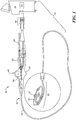
- FIG. 1 an embodiment of a medical system constructed in accordance with principles of the present invention is shown in FIG. 1 and generally designated as "10."
- the system 10 generally includes a medical device 12 that may be coupled to a control unit 14 or operating console.
- the medical device 12 may generally include one or more diagnostic or treatment regions for energetic, therapeutic and/or investigatory interaction between the medical device 12 and a treatment site.
- the treatment region(s) may deliver, for example, electroporation energy to a tissue area in proximity to the treatment region(s).
- the medical device 12 may include an elongate body 16 passable through a patient's vasculature and/or positionable proximate to a tissue region for diagnosis or treatment, such as a catheter, sheath, or intravascular introducer.
- the elongate body 16 may define a proximal portion 18 and a distal portion 20, and may further include one or more lumens disposed within the elongate body 16 thereby providing mechanical, electrical, and/or fluid communication between the proximal portion of the elongate body 16 and the distal portion of the elongate body 16.
- the distal portion 20 may generally define the one or more treatment region(s) of the medical device that are operable to monitor, diagnose, and/or treat a portion of a patient.
- the treatment region(s) may have a variety of configurations to facilitate such operation.
- the distal portion may include a segment configurable or deployable into a plurality of windings 22.
- the windings 22 may include a segment traversing greater than a 360 degree circumference with a changing radius between one or more portions of the windings 22.
- the windings 22 may be substantially planar with respect to one another, e.g., the windings 22 may have a decreasing radius such that one portion of the windings 22 circumscribes or surrounds another portion of the windings 22, with the windings 22 being oriented parallel to one another in a substantially single plane.
- the planar orientation of the windings 22 may facilitate ease of placement of the distal portion 20 of the device 12 into small, compact anatomical positions while achieving a large treatment or diagnoses surface area of the device.
- one or more portions of the windings 22 may include one or more electrically conductive surface(s) 24, such as one or more electrodes, or alternatively the windings 22 may constitute a substantially continuous electrically conductive surface along a substantial portion of their length.
- the distal portion 20 may include a shaft 26 at least partially disposed within a portion of the elongate body 16.
- the shaft 26 may extend or otherwise protrude from a distal end of the elongate body 16, and may be movable with respect to the elongate body 16 in longitudinal and rotational directions. That is, the shaft 26 may be slidably and/or rotatably moveable with respect to the elongate body 16.
- the shaft 26 may further define a lumen 24 therein for the introduction and passage of a guide wire 28 and/or another treatment or diagnostic instrument (not shown).
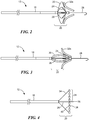
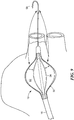
- the distal portion 20 may include one or more deployable arms 30 movably coupled to the shaft 26 and/or the elongate body 16, where one or more of the arms 30 may include an electrically conductive surface and/or electrode(s) 24 to deliver or conduct electrical pulses to a designated treatment area.
- the arms 30 may be disposed around a circumference of the shaft 26 and/or the elongate body 16, where the shaft 26 may be controllably moved to manipulate and expansions or radial distance between the arms 30 and the shaft/elongate body.
- the selectively adjustable radius of the arms 30 allows engagement and subsequent diagnosis or treatment of varying anatomical tissue structures which may include different geometries or dimensions. For example, as shown in FIG.
- the arms 30 may be expanded to contact a larger radius or portion of a tissue wall or structure 32a.
- the arms 30 may be manipulated into a smaller radius with respect to the shaft 26 and/or elongate body 16 to engage a vessel or lumen tissue structure 32b having a smaller diameter.
- the arms 30 may be extendable into a substantially linear configuration.
- the arms 30 may attach to the shaft 26 through a hinge or other pivoting mechanism allowing the arms 30 to open substantially parallel to one another and substantially transverse to the shaft or a longitudinal axis of the elongate body.
- the extension and/or retraction of the arms 30 may be facilitated in part by one or more steering wires 34 coupled to portions of the arms 30, and/or one or more expandable elements positioned within or otherwise coupled to the arms 30, as described in more detail below.
- the medical device 12 may also include a needle 36 that is controllably extendable and retractable from a distal portion of the device 12, such as the shaft 26 or elongate body 16.
- the needle 36 may include an electrically conductive surface to aid in mapping, ablating or otherwise electrically interacting with a targeted tissue region, such as that in the heart for example. Further, the needle 36 may aid in anchoring or securing the distal portion of the device 12 to the desired anatomy.
- the conductive surface or surfaces of the needle may include raised profile or larger diameter conductive features or rings to effect improved local depolarization of myocardial cells to allow measurement of the repolarization of cells surrounding those depolarized cells.
- the needle 36 may also be employed to deliver agents, including electrolytes such as sodium, potassium, or calcium to alter the ionic balance of cells exposed to electroporative energy deliveries, thereby enhancing the lethality of such energy deliveries to such tissues exposed to the delivered agents and energy applications.
- the electrically conductive regions and/or electrodes 24 described above may include variations in their electrically conductive and isolative characteristics.
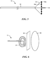
- the electrodes 24 may include a highly conductive first surface or face 38 oriented in the direction where contact or engagement with a tissue site is likely to occur, i.e., such as a distal face or surface.
- the electrodes 24 may further include less conductive, insulated segment or portion 40 on the regions of the electrode or surface less likely to contact or interact with tissue to be diagnosed or treated, such as a proximally-facing or oriented surface or portion of the electrode.
- the insulated portion 40 can increase the efficiency of the device 12 by directing diagnostic or treatment energies towards the engaged parts of the device 12.
- the electrodes 24 may be divided into two or more electrically conductive portions delineated or separated by an electrically insulated segment.
- the electrodes 24 may include a distally-facing surface 38a to engage tissue for treatment, while a proximally-facing surface includes a second conductive surface 38b providing an electrical reference point that is electrically isolated from the distally-facing surface 38a.
- the distally (tissue)-facing conductive surface 38a may include geometrical characteristics or dimensions to evoke a monophasic action potential when in contact with a designated tissue site. Such geometrical characteristics would include raised features that result in a higher local myocardial tissue contact pressure, directly under such features.
- Such pressure causes local sustained depolarization of the underlying myocardial tissue, thereby allowing the measurement of a monophasic action potential signal from the myocardial tissue site when referenced against a proximal, non-myocardial tissue-facing or non myocardial tissue-contacting electrode.
- the medical device 12 may include a handle 42 coupled to the proximal portion of the elongate body 16.
- the handle 42 can include circuitry for identification and/or use in controlling of the medical device 12 or another component of the system 10. Additionally, the handle 42 may be provided with a fitting 44 for receiving a guide wire or another diagnostic/treatment instrument that may be passed into the lumen of the shaft.
- the handle 42 may also include connectors 46 that are matable to the control unit 14 to establish communication between the medical device 12 and one or more components or portions of the control unit 14.
- the handle 42 may also include one or more actuation or control features that allow a user to actively control, deflect, steer, or otherwise manipulate a distal portion of the medical device 12 from the proximal portion of the medical device 12.
- the handle 42 may include one or more components such as a lever or knob 48 for manipulating the elongate body 16 and/or additional components of the medical device 12.
- a pull wire 50 with a proximal end and a distal end may have its distal end anchored to the elongate body 16 at or near the distal portion 20.
- the proximal end of the pull wire 50 may be anchored to an element such as a cam in communication with and responsive to the lever 48.
- the medical device 12 may include an actuator element 52 that is movably coupled to the proximal portion of the elongate body 16 and/or the handle for the manipulation and movement of a portion of the medical device 12, such as the shaft 26 or the arms 30, for example.
- the actuator element 52 may include a thumb-slide, a push-button, a rotating lever, or other mechanical structure for providing a movable coupling to the elongate body 16, the handle 42, and/or the shaft 26.
- the actuator element 52 may be movably coupled to the handle 42 such that the actuator element 52 is movable into individual, distinct positions, and is able to be releasably secured in any one of the distinct positions.
- the struts 34 may be constructed of a superelastic material such as a nickel-titanium alloy. In such a configuration, mechanical control wires would not be required to deploy the arms 30. Retraction of the device into a delivery sheath would cause the arms 30 to compress and allow the device 12 to exit the body.
- the shaft 26 may be employed to apply retraction or extension force to the junction point of the arms 30 to aid in retraction or enhance contact with complex tissue morphologies.
- the shaft 26 may also provide a conduit or lumen for controllable deployment of the needle 36.
- the system 10 may include one or more treatment or diagnostic sources coupled to the medical device 12 for use in an operative procedure, such as irreversible electroporation ablation, for example.
- the control unit 14 may include a treatment energy source 54 as a treatment or diagnostic mechanism in communication with one or more portions of the medical device 12.
- the treatment energy source 54 may include an electrical current or pulse generator having a plurality of output channels, with each channel coupled to an individual electrode or electrically conductive portion 24 of the medical device 12.
- the treatment energy source 54 may be operable in one or more modes of operation, including for example: (i) bipolar energy delivery between at least two electrodes 24 or electrically-conductive portions (such as the needle 36, for example) of the medical device 12 within a patient's body, (ii) monopolar or unipolar energy delivery to one or more of the electrodes or electrically-conductive portions on the medical device 12 within a patient's body and through a patient return or ground electrode spaced apart from the electrodes of the medical device 12, such as on a patient's skin or on an auxiliary device positioned within the patient away from the medical device 12, for example, and (iii) a combination of the monopolar and bipolar modes.
- the treatment energy source 54 may provide electrical pulses to the medical device 12 to perform an electroporation procedure.
- Electroporation utilizes high electric field amplitude electrical pulses to effectuate a physiological modification (i.e., permeabilization) of the cells to which the energy is applied.
- Such pulses may preferably be short (e.g., nanosecond, microsecond, or millisecond pulse width) in order to allow application of high voltage without large flow of electrical current that would result in significant tissue heating.
- the pulsed energy induces the formation of microscopic pores or openings in the cell membrane.
- an electroporated cell can survive electroporation (i.e., "reversible electroporation") or die (i.e., irreversible electroporation, "IEP”).
- Reversible electroporation may be used to transfer agents, including large molecules, into targeted cells for various purposes.
- the treatment energy source 54 may be configured and programmed to deliver pulsed, high voltage electric fields as described below, appropriate for achieving desired pulsed, high voltage ablation (or IEP ablation).
- the pulsed, high voltage ablation effects of the present disclosure are distinguishable from DC current ablation, as well as thermally-induced ablation attendant with conventional RF techniques.
- the IEP in accordance with the present disclosure is sufficient to induce cell death for purposes of completely blocking an aberrant conductive pathway along or through cardiac tissue, destroying the ability of the so-ablated cardiac tissue to propagate or conduct cardiac depolarization waveforms and associated electrical signals.
- the treatment energy source 54 may deliver a number of different various waveforms or shapes of pulses to achieve electroporation ablation of cardiac tissue, including sinusoidal AC pulses, DC pulses, square wave pulses, exponentially decaying waveforms, or other pulse shapes such as combined AC/DC pulses, or DC shifted signals.
- the parameters of pulsed energy generated by the treatment energy source 58 can vary in one or more of the following manners: waveform shape, pulse polarity, amplitude, pulse duration, interval between pulses, number of pulses (frequency), combination of waveforms, etc. One or more of these parameters can be altered or changed during the ablation procedure.
- the treatment energy source 58 may be adapted to generate a high density energy gradient in the range of 10-1,000 V/cm, pulsed at rates on the order of 0.001-1,000 microseconds.
- the voltage level, pulse rate, waveform, and other parameters can be varied as described below, with the control unit 14 including, in some embodiments, a controller that automatically dictates operational parameters as a function of one or more characteristics of the cardiac tissue target site (e.g., tissue type (such as fatty tissue, thickness, cell orientation, naturally-occurring electrical activity, etc.)).
- the treatment energy source 54 may be configured to deliver monophasic or biphasic electrical pulses to one or more electrically conductive portions of the medical device.
- monophasic electrical pulses may alternatively be employed
- the application of biphasic electrical pulses has surprisingly been found to produce unexpectedly beneficial results in the context of cardiac tissue ablation.
- biphasic electroporation pulses the direction of the pulses completing one cycle alternates in less than a few hundred microseconds.
- the cells to which the biphasic electrical pulses are applied undergo alternation of electrical field bias.
- changing the direction of bias surprisingly helps to reduce prolonged post-ablation depolarization and/or ion charging.
- biphasic electrical pulses overcome the high impedance characteristics of fatty cells often times associated with cardiac ablation procedures.
- biphasic electrical pulses avoid the possible drawbacks of monophasic electrical pulses including: 1) atrial or ventricular fibrillation, 2) less effective in making lesions through fat, 3) propensity to make thermal lesions on the anode side of an electrode pair, and 4) prolonged muscle excitation.
- the treatment energy source may be programmed to deliver a series of pulse trains that are timed to be delivered at the onset of local depolarization, each train preferably not lasting more than about 50 milliseconds to avoid energy delivery outside of the absolute refractory period.
- Each train can consist of 10 to 60 biphasic (i.e., half positive phase and half negative phase) pulses.
- an output voltage from the treatment energy source can be in the range of 200-1000 volts at currents in the range of 8-25 Amps. These output voltage levels (200-1000 volts) provide a voltage intensity delivered by the medical device 12 on the order of 200-1000 V/cm across 10 mm thick tissue, for example.
- the control unit 14 and/or the treatment energy source 54 may include one or more controllers, processors, and/or software modules containing instructions or algorithms to provide for the automated operation and performance of the features, sequences, calculations, or procedures described herein.
- the system 10 may further include one or more sensors to monitor the operating parameters throughout the system 10, including for example temperature, power delivery, impedance, or the like in the control unit 14 and/or the medical device 12, in addition to monitoring, recording or otherwise conveying measurements or conditions within the medical device 12 or the ambient environment at the distal portion of the medical device 12.
- the sensor(s) may be in communication with the control unit 14 for initiating or triggering one or more alerts or therapeutic delivery modifications during operation of the medical device 12.
- Such sensors may be employed to evaluate electrical path impedance prior to delivery of high voltage energy by delivering on or more low voltage test pulses to evaluate the tissue electrical path.
- the distal portion 20 of the medical device 12 may be positioned in proximity to a tissue region to be treated.
- the distal portion 20 may be positioned to contact an endocardial tissue region, such as a substantially continuous portion of an atrial wall, a circumference of a blood vessel such as a pulmonary vein, or the like.
- the distal portion 20 may be manipulated into the desired geometric configuration, including a selected radius of the windings 22, selective expansion or deployment of the arms 30, or the like through the actuator element 52 or other control or steering mechanism(s) operable at the handle 42.
- the electrically-conductive portions 24 of the distal portion 20 may be used to measure and/or record electrical signals or conduction pathways in the contacted tissue region, commonly referred to as "mapping."
- the targeted tissue region may be mapped to identify the location of abnormal signal pathways for subsequent therapy or treatment.
- the medical device 12 may be used to treat the designated tissue area.
- the medical device 12 may be operated to deliver electroporating energy pulses through the conductive portions 24 of the distal portion 20 to achieve IEP ablation of the targeted tissue.
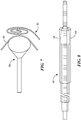
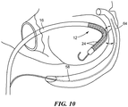
- the medical device 12 having the plurality of windings 22 may be positioned adjacent an endocardial surface 56 of the heart, while a return electrode or other secondary electrically conductive tool 58 may be positioned away from the medical device, such as on an epicardial surface 60 of the heart or affixed on an exterior surface of the patient, to complete the circuit for electrical delivery.
- the medical device 12 may be placed adjacent to an epicardial surface 60 of the heart, such as within the pericardial space, with another medical device or instrument 58 (which may include, for example, a second medical device similar to any of the configurations of the medical device 12 described herein or in Application Serial No. 13/194,180, filed July 29, 2011 , entitled “Mesh-Overlayed Ablation and Mapping Device,” ) residing on an interior or endocardial position of the heart for electrical conduction between the two devices, and thus the tissue disposed therebetween (as shown in FIG. 7 ).
- another medical device or instrument 58 which may include, for example, a second medical device similar to any of the configurations of the medical device 12 described herein or in Application Serial No. 13/194,180, filed July 29, 2011 , entitled “Mesh-Overlayed Ablation and Mapping Device," residing on an interior or endocardial position of the heart for electrical conduction between the two devices, and thus the tissue disposed therebetween (as shown in FIG. 7 ).
- the substantially planar windings 22 provide a reduced profile easing insertion into compact spaces, such as within the pericardial space or near the atrial-ventricular groove region of the heart, to provide a local vector for energy flow between the windings and/or electrodes thereon and the electrodes on the intracardiac device.
- the medical device 12 may be positioned on the left atrial wall, with electrodes contacting the endocardium in proximity to the ostium of the left inferior pulmonary vein, extending to the annulus of the mitral valve.
- the secondary electrically conductive tool 58 may be placed within the coronary sinus or in the pericardial space, adjacent the medical device 12. Now referring to FIG.
- an exemplary configuration of the secondary electrically conductive tool 58 may include a diagnostic catheter or intravenous device, such as a coronary sinus mapping catheter, with an expandable conductive mesh 59 coupled to and/or slidable along a body of the tool 58.
- the expandable mesh 59 serves as an energy return path from the medical device 12.
- the secondary electrically conductive tool 58 may include one or more slidable sheath(s) 61 slidably advanced over the body of the device 58 that can be advanced to a distal end of the tool 58 to selectively cover or expose conductive portions of the mesh 59.
- the tool 58 including the sheath 61 and/or expandable mesh 59, may include one or more controllable mechanisms (not shown) such as pull-wires or the like to selectively control the exposure and/or expansion of the mesh.
- the mesh 59 may be biased towards a particular expanded configuration or shape, where the one or more sheaths 61 are manipulated to restrict or allow the biased configuration of the mesh 59.
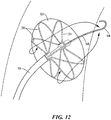
- the medical device 12 is shown positioned in an endocardial space, such as an atrium of the heart.
- the medical device 12 may include an expandable or inflatable element 62 operable to expand or otherwise control the position or configuration of the arms 30 and the electrodes 24.
- the inflatable element 62 may be positioned such that it occludes an orifice in the heart wall, such as an ostium of a pulmonary vein.
- the secondary electrically conductive tool 58 may include a guide wire passable through the medical device 12 such that a portion of the guide wire extends distally from the medical device 12 into the pulmonary vein.
- the distally-extending portion of the guide wire may include one or more electrically conductive surfaces 64 for the conduction of one or more electrical pulses (1) between the electrically conductive surface(s) 64 and the electrodes 24 of the medical device 12, and/or (2) between two or more of the electrodes on the medical device 12, as indicated by the illustrated arrows.
- This energy delivery vector may provide both longitudinal and circumferential treatment patterns in the affected tissue.
- the medical device 12 may be positioned along an endocardial wall or surface while the secondary electrically conductive tool 58, which may include a guide wire, is routed through a portion of the coronary sinus.
- One or more electrical pulses may be conducted between the electrodes 24 of the medical device 12 and the electrically conductive surface(s) 64 of the secondary electrically conductive tool 58, as indicated by the illustrated arrows.
- This energy delivery vector may provide substantially linear or curvilinear treatment patterns in the affected tissue when treating the mitral isthmus region, for example. As shown in FIG.
- the medical device 12 may be positioned against an upper wall or roof of an atrium, while the secondary electrically conductive tool 58 is routed through a portion of the superior vena cava and/or left subclavian vein.
- One or more electrical pulses may be conducted between the electrodes 24 of the medical device 12 and the electrically conductive surface(s) 64 of the secondary electrically conductive tool 58, as indicated by the illustrated arrows.
- This energy delivery vector may also provide substantially linear or curvilinear treatment patterns in the affected tissue.
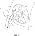
- the medical device 12 may be positioned with a proximal portion of the arms 30 and/or electrodes 24 against a septal wall.
- the secondary electrically conductive tool 58 may be passed through the medical device 12 such that a portion of the guide wire extends distally from the medical device 12 into the cardiac cavity.
- the secondary electrically conductive tool 58 may be positioned proximally of the electrodes 24 and/or on an opposite side of the septal wall.
- One or more electrical pulses may be conducted (1) between the electrically conductive surface(s) 64 and the electrodes 24 of the medical device 12, and/or (2) between two or more of the electrodes on the medical device 12, as indicated by the illustrated arrows.
- This energy delivery vector may selectively provide longitudinal and/or circumferential treatment patterns in the affected tissue.
- Varying the position and/or alignment of the one or more instituted medical devices may include epicardial placement into the pericardial space with alignment for vectored energy return from the medical device 12, with the secondary electrically conductive tool 58 deployed in alignment with the atrial-ventricular groove, adjacent the posterior left atrial wall near the left inferior pulmonary vein and mitral valve annulus.
- Such placement would promote energy vectoring to produce an effective "left atrial isthmus" lesion, connecting the left inferior pulmonary vein ostial region with the mitral valve annulus.
- the secondary electrically conductive tool 58 may be placed into the pericardial space and advanced into the transverse sinus over the anterior portion of the left atrium to serve as a vectored energy return path that enhances lesion formation connecting the right and left pulmonary vein ostial regions with a linear or other conduction block, also known as a left atrial "dome lesion".
- the IEP ablation may proceed employing one or more of the energy delivery characteristics described above.
- a string of biphasic pulses may be delivered over a brief period, with each train or train segment comprised of 40 pulses over 8 milliseconds at a frequency gated to one pulse train delivered at each onset of depolarization of the myocardium for a series of five heartbeats to effect ablation of the targeted cardiac tissue by IEP.
- Exemplary pulse trains may include a biphasic pulse width of 5 microseconds and inter-pulse interval of 20 microseconds, for example.
- biphasic energy pulses may be applied at very short durations (on the order of 1 nanosecond - 50 microseconds, up to 100 microseconds, in some embodiments in the range of 20-200 microseconds) to effectively ablate fatty areas of heart tissue.
- trains of short biphasic pulses having low amplitude can be effective in the permeabilization of cells while minimizing thermal damage.
- Such delivered pulse trains of energy may include a plurality of pulses each having a cycle time of not more than 5 milliseconds, but preferably not more than 50 microseconds; an output voltage between approximately 200-2000 volts, preferably between 500 and 1000 volts at a pulse width between approximately 0.005 microseconds - 5 milliseconds, preferably between 0.005microseconds and 50 microseconds; and/or a series of pulse trains, with each train having between approximately 1-500 monophasic or biphasic pulses, preferably 10-100 pulses. Delivery of energy pulse trains are preferably timed to correspond with the onset of depolarization of the myocardium. Alternately the pulse trains may be delivered to myocardium that is fully polarized, just before normal sinus rhythm.
- the system 10 and related cardiac ablation methods may be adapted to correlate delivery of energy with the natural or paced depolarization-repolarization cycle of the cardiac muscle in a beating heart.
- the electrically conductive portions 24 of the medical device 12 may be used to sensing electrical activity propagating along cardiac tissue; or, alternatively, a separate electrical sensing component (not shown) apart from the medical device 12 can be employed.
- the control unit 14 may interpret the sensed electrical activity, and based upon this interpretation, dictate and/or adjust timing of the delivery of the pulsed electroporation-causing energy by the treatment energy source.
- the sensed, naturally-occurring electrical activity can be provided in the series of waveforms observed on an intracardiac electrogram (EGM) or electrocardiogram (ECG).
- ECG intracardiac electrogram
- ECG electrocardiogram
- a typical ECG tracing of a normal heartbeat (or cardiac cycle) consists of a P wave, a QRS wave complex, and a T wave.
- the main electrical vector is directed from the SA node towards the AV node and spreads from the right atrium to the left atrium. This correlates with the P wave on the ECG.
- the QRS wave complex is a representation on the ECG that corresponds with the depolarization of the ventricles.
- the QRS wave complex is larger than the P wave.
- the T wave represents the repolarization (or recovery) of the ventricles.
- the QRS wave complex is an indication that the cardiac myocytes in the ventricles have depolarized, causing contraction of the heart.
- the T wave is an indication that the ventricular cardiac myocytes have repolarized and are prepared to repeat the depolarization observed again as a QRS wave complex.
- the system 10 may time the delivery of high voltage, pulsed energy as a function of the sensed cardiac cycle to which the delivery of pulsed, high voltage energy is guided. Further, the determined timing may be modified and/or selected not only based on the sensed/paced cardiac cycle, but also of the specific tissue to be ablated. For example, with ventricular cardiac tissue, high density energy pulses (as described above) may be applied during the QRS wave complex or segment. During the QRS wave complex, the ventricular cells are actively pumping ions through the cell membranes to effect depolarization. By timing the pulsed, electroporation energy with this period, the high voltage energy may be applied when the local cellular lethal threshold for high voltage pulses is reduced. This, in turn, allows more efficient use of the applied high voltage to cause cell death and local conduction block. Notably, with embodiments in which the delivery of pulsed, high voltage is tailored as a function of heart rate, frequencies of less than 1 Hz are beneficial.
- the time or gated delivery of high voltage, pulsed energy can assume a different format where the tissue to be ablated is atrial tissue. More particularly, the pulsed, high voltage energy can be optimized in ablation of atrial myocardium using the P wave portion of the ECG recording as the gating reference point in the cardiac cycle.
- the atrial myocardium cells exhibit a reduced threshold for high voltage pulses when depolarizing; by timing the delivery or gating of pulsed, high voltage energy to correspond with the P wave segment, enhanced cardiac ablation or atrial tissue is promoted with lower output voltage gradients.
- the tissue ablation systems and methods of the present disclosure provide a marked improvement over previous applications.
- the IEP energy delivery may be performed with a series of microsecond or nanosecond duration, high voltage pulses.
- the delivery is non-thermal and does not require saline irrigation to cool the electrodes. Accordingly, heat-sink issues encountered with conventional thermal ablations are eliminated, including the problem of irrigation fluid overload in fluid compromised patients during an atrial fibrillation ablation procedure.
- the duration of IEP energy delivery may extend for a matter of seconds rather than minutes on end, which is a major reduction in time required to perform a procedure.
- IEP ablation eliminates the risk of complications such as esophageal fistulae, pulmonary vein stenosis, and phrenic nerve palsy associated with other ablation techniques and durations.
- radiofrequency hyperthermal ablation may disrupt the cardiac endothelial surface, activate the extrinsic coagulation cascade, and lead to char and thrombus formation, which in turn may lead to systemic thromboembolism - all of which IEP avoids.
Landscapes
- Health & Medical Sciences (AREA)
- Life Sciences & Earth Sciences (AREA)
- Engineering & Computer Science (AREA)
- Veterinary Medicine (AREA)
- Biomedical Technology (AREA)
- Nuclear Medicine, Radiotherapy & Molecular Imaging (AREA)
- Surgery (AREA)
- Animal Behavior & Ethology (AREA)
- General Health & Medical Sciences (AREA)
- Public Health (AREA)
- Physics & Mathematics (AREA)
- Cardiology (AREA)
- Biophysics (AREA)
- Plasma & Fusion (AREA)
- Otolaryngology (AREA)
- Radiology & Medical Imaging (AREA)
- Heart & Thoracic Surgery (AREA)
- Medical Informatics (AREA)
- Molecular Biology (AREA)
- Surgical Instruments (AREA)
Claims (5)
- Medizinisches System (10), das Folgendes umfasst:eine medizinische Vorrichtung (12) mit mehreren ebenen Wicklungen (22), wobei die mehreren ebenen Wicklungen (22) einen elektrisch leitenden Abschnitt (24) einschließen; undeinen elektrischen Impulsgenerator, der mit dem elektrisch leitenden Abschnitt (24) gekoppelt ist, wobei der elektrische Impulsgenerator so programmiert ist, dass er gepulste zweiphasige Hochspannungselektroporationsimpulse an den elektrisch leitenden Abschnitt (24) abgibt, um eine irreversible Elektroporation von Herzgewebe zu induzieren, wobei die zweiphasigen Elektroporationsimpulse Energie bei einer Ausgangsspannung zwischen 200 und 2000 Volt bei einer Impulsbreite von 5 µs und einem Zwischenimpulsintervall von 20 µs einschließen, wobei die zweiphasigen Elektroporationsimpulse eine Reihe von Impulsfolgen einschließen, wobei jede Folge 40 Impulse aufweist.
- Medizinisches System (10) nach Anspruch 1, wobei die medizinische Vorrichtung (12) einen intravaskuläre Katheterkörper (16) einschließt, der mit den mehreren planaren Wicklungen (22) gekoppelt ist.
- Medizinisches System (10) nach Anspruch 1, wobei der elektrisch leitfähige Abschnitt (24) zumindest eine Elektrode (24) einschließt.
- Medizinisches System (10) nach Anspruch 1, wobei die zweiphasigen Elektroporationsimpulse mehrere Impulse einschließen, die jeweils eine Zykluszeit von nicht mehr als 5 Millisekunden aufweisen.
- Medizinisches System (10) nach Anspruch 1, das ferner ein elektrisch leitendes Werkzeug (58) mit einem elektrisch leitenden Abschnitt (59) umfasst, wobei das elektrisch leitende Werkzeug (58) unabhängig von der medizinischen Vorrichtung (12) positionierbar ist, wobei die zweiphasigen Elektroporationsimpulse, die von dem elektrischen Impulsgenerator an den elektrisch leitenden Abschnitt (24) der medizinischen Vorrichtung (12) abgegeben werden, zwischen dem elektrisch leitenden Abschnitt (24) der medizinischen Vorrichtung (12) und dem elektrisch leitenden Abschnitt (59) des elektrisch leitendes Werkzeug (58) vorbeigehen, um einen Energieabgabevektor zu erzeugen, wobei eine Position des elektrisch leitenden Werkzeugs (58) relativ zu der medizinischen Vorrichtung (12) die Form des Energieabgabevektors beeinflusst.
Priority Applications (2)
| Application Number | Priority Date | Filing Date | Title |
|---|---|---|---|
| EP19218891.0A EP3656329B1 (de) | 2011-07-29 | 2012-07-13 | Intrakardiale instrument zur verabreichung von elektroporationstherapien |
| EP24175472.0A EP4410360A3 (de) | 2011-07-29 | 2012-07-13 | Intrakardiales werkzeug zur verabreichung von elektroporationstherapien |
Applications Claiming Priority (2)
| Application Number | Priority Date | Filing Date | Title |
|---|---|---|---|
| US13/194,259 US20130030430A1 (en) | 2011-07-29 | 2011-07-29 | Intracardiac tools and methods for delivery of electroporation therapies |
| PCT/US2012/046617 WO2013019385A1 (en) | 2011-07-29 | 2012-07-13 | Intracardiac tools and methods for delivery of electroporation therapies |
Related Child Applications (3)
| Application Number | Title | Priority Date | Filing Date |
|---|---|---|---|
| EP19218891.0A Division EP3656329B1 (de) | 2011-07-29 | 2012-07-13 | Intrakardiale instrument zur verabreichung von elektroporationstherapien |
| EP19218891.0A Division-Into EP3656329B1 (de) | 2011-07-29 | 2012-07-13 | Intrakardiale instrument zur verabreichung von elektroporationstherapien |
| EP24175472.0A Division EP4410360A3 (de) | 2011-07-29 | 2012-07-13 | Intrakardiales werkzeug zur verabreichung von elektroporationstherapien |
Publications (2)
| Publication Number | Publication Date |
|---|---|
| EP2736434A1 EP2736434A1 (de) | 2014-06-04 |
| EP2736434B1 true EP2736434B1 (de) | 2020-02-19 |
Family
ID=46582073
Family Applications (3)
| Application Number | Title | Priority Date | Filing Date |
|---|---|---|---|
| EP19218891.0A Active EP3656329B1 (de) | 2011-07-29 | 2012-07-13 | Intrakardiale instrument zur verabreichung von elektroporationstherapien |
| EP24175472.0A Pending EP4410360A3 (de) | 2011-07-29 | 2012-07-13 | Intrakardiales werkzeug zur verabreichung von elektroporationstherapien |
| EP12740260.0A Active EP2736434B1 (de) | 2011-07-29 | 2012-07-13 | Intrakardiale instrument zur verabreichung von elektroporationstherapien |
Family Applications Before (2)
| Application Number | Title | Priority Date | Filing Date |
|---|---|---|---|
| EP19218891.0A Active EP3656329B1 (de) | 2011-07-29 | 2012-07-13 | Intrakardiale instrument zur verabreichung von elektroporationstherapien |
| EP24175472.0A Pending EP4410360A3 (de) | 2011-07-29 | 2012-07-13 | Intrakardiales werkzeug zur verabreichung von elektroporationstherapien |
Country Status (4)
| Country | Link |
|---|---|
| US (6) | US20130030430A1 (de) |
| EP (3) | EP3656329B1 (de) |
| CN (2) | CN109793571B (de) |
| WO (1) | WO2013019385A1 (de) |
Cited By (35)
| Publication number | Priority date | Publication date | Assignee | Title |
|---|---|---|---|---|
| US11432871B2 (en) | 2017-04-10 | 2022-09-06 | St. Jude Medical, Cardiology Division, Inc. | Electroporation system and method of preconditioning tissue for electroporation therapy |
| US11850051B2 (en) | 2019-04-30 | 2023-12-26 | Biosense Webster (Israel) Ltd. | Mapping grid with high density electrode array |
| US11878095B2 (en) | 2018-12-11 | 2024-01-23 | Biosense Webster (Israel) Ltd. | Balloon catheter with high articulation |
| US11918341B2 (en) | 2019-12-20 | 2024-03-05 | Biosense Webster (Israel) Ltd. | Selective graphical presentation of electrophysiological parameters |
| US11918383B2 (en) | 2020-12-21 | 2024-03-05 | Biosense Webster (Israel) Ltd. | Visualizing performance of catheter electrodes |
| US11950841B2 (en) | 2020-09-22 | 2024-04-09 | Biosense Webster (Israel) Ltd. | Basket catheter having insulated ablation electrodes and diagnostic electrodes |
| US11950930B2 (en) | 2019-12-12 | 2024-04-09 | Biosense Webster (Israel) Ltd. | Multi-dimensional acquisition of bipolar signals from a catheter |
| US11950840B2 (en) | 2020-09-22 | 2024-04-09 | Biosense Webster (Israel) Ltd. | Basket catheter having insulated ablation electrodes |
| US11974803B2 (en) | 2020-10-12 | 2024-05-07 | Biosense Webster (Israel) Ltd. | Basket catheter with balloon |
| US11987017B2 (en) | 2020-06-08 | 2024-05-21 | Biosense Webster (Israel) Ltd. | Features to assist in assembly and testing of devices |
| US11992259B2 (en) | 2018-04-11 | 2024-05-28 | Biosense Webster (Israel) Ltd. | Flexible multi-arm catheter with diametrically opposed sensing electrodes |
| US12004804B2 (en) | 2021-09-09 | 2024-06-11 | Biosense Webster (Israel) Ltd. | Basket catheter with mushroom shape distal tip |
| US12011280B2 (en) | 2021-10-04 | 2024-06-18 | Biosense Webster (Israel) Ltd. | Electrophysiological mapping in the presence of injury current |
| US12029545B2 (en) | 2017-05-30 | 2024-07-09 | Biosense Webster (Israel) Ltd. | Catheter splines as location sensors |
| US12042246B2 (en) | 2016-06-09 | 2024-07-23 | Biosense Webster (Israel) Ltd. | Multi-function conducting elements for a catheter |
| US12048479B2 (en) | 2020-09-10 | 2024-07-30 | Biosense Webster (Israel) Ltd. | Surface mounted electrode catheter |
| US12064170B2 (en) | 2021-05-13 | 2024-08-20 | Biosense Webster (Israel) Ltd. | Distal assembly for catheter with lumens running along spines |
| US12076071B2 (en) | 2020-08-14 | 2024-09-03 | Kardium Inc. | Systems and methods for treating tissue with pulsed field ablation |
| US12082875B2 (en) | 2020-09-24 | 2024-09-10 | Biosense Webster (Israel) Ltd | Balloon catheter having a coil for sensing tissue temperature and position of the balloon |
| US12201786B2 (en) | 2020-12-17 | 2025-01-21 | Biosense Webster (Israel) Ltd. | Measurement of distal end dimension of catheters using magnetic fields |
| US12232874B2 (en) | 2020-05-29 | 2025-02-25 | Biosense Webster (Israel) Ltd. | Electrode apparatus for diagnosis of arrhythmias |
| US12295720B2 (en) | 2019-07-18 | 2025-05-13 | Biosense Webster (Israel) Ltd | Visual guidance for positioning a distal end of a medical probe |
| US12329531B2 (en) | 2018-12-28 | 2025-06-17 | Biosense Webster (Israel) Ltd. | Mapping ECG signals using a multipole electrode assembly |
| US12364426B2 (en) | 2021-08-12 | 2025-07-22 | Biosense Webster (Israel) Ltd. | Electro-anatomical mapping and annotation presented in electrophysiological procedures |
| US12419683B2 (en) | 2021-12-22 | 2025-09-23 | Biosense Webster (Israel) Ltd. | Irreversible electroporation with shorted electrodes |
| US12440263B2 (en) | 2022-01-20 | 2025-10-14 | Biosense Webster (Israel) Ltd. | Systems and methods for tripodic spines forming a spherical basket for improved tissue contact and current delivery |
| US12446946B2 (en) | 2022-01-20 | 2025-10-21 | Biosense Webster (Israel) Ltd. | Systems and methods for a single spiral electrode assembly forming a spherical basket for improved tissue contact and current delivery |
| US12471989B2 (en) | 2022-04-28 | 2025-11-18 | Biosense Webster (Israel) Ltd. | Strengthened expandable baskets for medical probes and medical probes containing strengthen expandable baskets |
| US12478424B2 (en) | 2021-09-10 | 2025-11-25 | Biosense Webster (Israel) Ltd. | Staggered pairs of biased ablation electrodes on basket catheter |
| US12484961B2 (en) | 2022-01-20 | 2025-12-02 | Biosense Webster (Israel) Ltd. | Mechanical retainer systems for electrodes of a basket catheter, and methods of the same |
| US12521035B2 (en) | 2022-12-29 | 2026-01-13 | Biosense Webster (Israel) Ltd. | Cylindrical cage systems and methods for distributed tissue contact for mapping and ablation |
| US12533185B2 (en) | 2022-12-28 | 2026-01-27 | Biosense Webster (Israel) Ltd. | Basket end effector with distal position sensor |
| US12533489B2 (en) | 2021-10-08 | 2026-01-27 | Biosense Webster (Israel) Ltd. | Measuring tissue proximity for multi-electrode catheter |
| US12539085B2 (en) | 2019-08-27 | 2026-02-03 | Biosense Webster (Israel) Ltd. | Accurate basket catheter tracking |
| US12616517B2 (en) | 2023-02-24 | 2026-05-05 | Biosense Webster (Israel) Ltd. | Expandable basket assemblies with linear spine patterns for improved tissue contact and methods for making thereof |
Families Citing this family (153)
| Publication number | Priority date | Publication date | Assignee | Title |
|---|---|---|---|---|
| US7655004B2 (en) | 2007-02-15 | 2010-02-02 | Ethicon Endo-Surgery, Inc. | Electroporation ablation apparatus, system, and method |
| US8888792B2 (en) | 2008-07-14 | 2014-11-18 | Ethicon Endo-Surgery, Inc. | Tissue apposition clip application devices and methods |
| US8157834B2 (en) | 2008-11-25 | 2012-04-17 | Ethicon Endo-Surgery, Inc. | Rotational coupling device for surgical instrument with flexible actuators |
| US8361066B2 (en) | 2009-01-12 | 2013-01-29 | Ethicon Endo-Surgery, Inc. | Electrical ablation devices |
| US8632534B2 (en) | 2009-04-03 | 2014-01-21 | Angiodynamics, Inc. | Irreversible electroporation (IRE) for congestive obstructive pulmonary disease (COPD) |
| WO2010138919A2 (en) | 2009-05-28 | 2010-12-02 | Angiodynamics, Inc. | System and method for synchronizing energy delivery to the cardiac rhythm |
| US9895189B2 (en) | 2009-06-19 | 2018-02-20 | Angiodynamics, Inc. | Methods of sterilization and treating infection using irreversible electroporation |
| US20110098704A1 (en) | 2009-10-28 | 2011-04-28 | Ethicon Endo-Surgery, Inc. | Electrical ablation devices |
| US20110098694A1 (en) * | 2009-10-28 | 2011-04-28 | Ethicon Endo-Surgery, Inc. | Methods and instruments for treating cardiac tissue through a natural orifice |
| US9028483B2 (en) | 2009-12-18 | 2015-05-12 | Ethicon Endo-Surgery, Inc. | Surgical instrument comprising an electrode |
| EP2627274B1 (de) | 2010-10-13 | 2022-12-14 | AngioDynamics, Inc. | System zur elektrischen ableitung des gewebes eines patienten |
| US9233241B2 (en) | 2011-02-28 | 2016-01-12 | Ethicon Endo-Surgery, Inc. | Electrical ablation devices and methods |
| US9254169B2 (en) | 2011-02-28 | 2016-02-09 | Ethicon Endo-Surgery, Inc. | Electrical ablation devices and methods |
| US9049987B2 (en) | 2011-03-17 | 2015-06-09 | Ethicon Endo-Surgery, Inc. | Hand held surgical device for manipulating an internal magnet assembly within a patient |
| WO2012145073A1 (en) | 2011-04-22 | 2012-10-26 | Topera, Inc. | Basket style cardiac mapping catheter having spline bends for detection of cardiac rhythm disorders |
| US9078665B2 (en) | 2011-09-28 | 2015-07-14 | Angiodynamics, Inc. | Multiple treatment zone ablation probe |
| US9414881B2 (en) | 2012-02-08 | 2016-08-16 | Angiodynamics, Inc. | System and method for increasing a target zone for electrical ablation |
| US9427255B2 (en) | 2012-05-14 | 2016-08-30 | Ethicon Endo-Surgery, Inc. | Apparatus for introducing a steerable camera assembly into a patient |
| US9078662B2 (en) | 2012-07-03 | 2015-07-14 | Ethicon Endo-Surgery, Inc. | Endoscopic cap electrode and method for using the same |
| US9545290B2 (en) | 2012-07-30 | 2017-01-17 | Ethicon Endo-Surgery, Inc. | Needle probe guide |
| US10314649B2 (en) | 2012-08-02 | 2019-06-11 | Ethicon Endo-Surgery, Inc. | Flexible expandable electrode and method of intraluminal delivery of pulsed power |
| US9572623B2 (en) | 2012-08-02 | 2017-02-21 | Ethicon Endo-Surgery, Inc. | Reusable electrode and disposable sheath |
| JP6301926B2 (ja) * | 2012-08-09 | 2018-03-28 | ユニバーシティ オブ アイオワ リサーチ ファウンデーション | カテーテル、カテーテルシステム、及び組織構造を刺通する方法 |
| US9277957B2 (en) | 2012-08-15 | 2016-03-08 | Ethicon Endo-Surgery, Inc. | Electrosurgical devices and methods |
| AU2013365634A1 (en) | 2012-12-20 | 2015-05-21 | Renal Dynamics Ltd. | Multi point treatment probes and methods of using thereof |
| US20140200639A1 (en) | 2013-01-16 | 2014-07-17 | Advanced Neuromodulation Systems, Inc. | Self-expanding neurostimulation leads having broad multi-electrode arrays |
| US10098527B2 (en) | 2013-02-27 | 2018-10-16 | Ethidcon Endo-Surgery, Inc. | System for performing a minimally invasive surgical procedure |
| WO2014195933A1 (en) * | 2013-06-05 | 2014-12-11 | Tel Hashomer Medical Research Infrastructure And Services Ltd. | Myocardial ablation by irreversible electroporation |
| WO2015103574A1 (en) | 2014-01-06 | 2015-07-09 | Iowa Approach Inc. | Apparatus and methods for renal denervation ablation |
| US10441338B2 (en) | 2014-01-14 | 2019-10-15 | Medtronic Cryocath Lp | Balloon catheter with fluid injection elements |
| US9918790B2 (en) | 2014-01-23 | 2018-03-20 | Old Dominion University Research Foundation | Ablation of myocardial tissues with nanosecond pulsed electric fields |
| EP4670627A3 (de) * | 2014-05-07 | 2026-03-25 | Boston Scientific Scimed, Inc. | Verfahren und vorrichtung zur selektiven gewebeablation |
| WO2015175944A1 (en) | 2014-05-16 | 2015-11-19 | Gary Long | Methods and apparatus for multi-catheter tissue ablation |
| WO2015192018A1 (en) | 2014-06-12 | 2015-12-17 | Iowa Approach Inc. | Method and apparatus for rapid and selective tissue ablation with cooling |
| EP3154463B1 (de) | 2014-06-12 | 2019-03-27 | Farapulse, Inc. | Vorrichtung für schnelle und selektive transurethrale gewebeablation |
| US12114911B2 (en) | 2014-08-28 | 2024-10-15 | Angiodynamics, Inc. | System and method for ablating a tissue site by electroporation with real-time pulse monitoring |
| EP3206613B1 (de) | 2014-10-14 | 2019-07-03 | Farapulse, Inc. | Vorrichtung zur schnellen und sicheren lungenvenenherzablation |
| US10271893B2 (en) * | 2014-12-15 | 2019-04-30 | Medtronic Ablation Frontiers Llc | Timed energy delivery |
| JP6514334B2 (ja) | 2015-01-28 | 2019-05-15 | セント・ジュード・メディカル,カーディオロジー・ディヴィジョン,インコーポレイテッド | 熱マッピング・カテーテル |
| ES2807439T3 (es) * | 2015-03-31 | 2021-02-23 | Oncosec Medical Inc | Sistemas para electroporación mejorada basada en la detección de tejidos |
| CN107635496B (zh) * | 2015-05-12 | 2021-08-17 | 圣犹达医疗用品电生理部门有限公司 | 用于交流心脏不可逆电穿孔的非对称平衡波形 |
| DE202016009219U1 (de) * | 2015-08-06 | 2024-05-13 | Medtronic, Inc. | Herzablation mittels gepulsten Feldes |
| AU2016335755B2 (en) | 2015-10-07 | 2021-07-01 | Mayo Foundation For Medical Education And Research | Electroporation for obesity or diabetes treatment |
| FR3043921B1 (fr) * | 2015-11-25 | 2019-07-26 | Airbus Operations | Systeme d'application d'un fluide sur une surface |
| CN108778172B (zh) * | 2016-01-05 | 2021-08-13 | 法拉普尔赛股份有限公司 | 用于将消融能量递送至组织的系统、设备和方法 |
| US10130423B1 (en) | 2017-07-06 | 2018-11-20 | Farapulse, Inc. | Systems, devices, and methods for focal ablation |
| US10660702B2 (en) | 2016-01-05 | 2020-05-26 | Farapulse, Inc. | Systems, devices, and methods for focal ablation |
| US12144541B2 (en) | 2016-01-05 | 2024-11-19 | Boston Scientific Scimed, Inc. | Systems, apparatuses and methods for delivery of ablative energy to tissue |
| US10172673B2 (en) | 2016-01-05 | 2019-01-08 | Farapulse, Inc. | Systems devices, and methods for delivery of pulsed electric field ablative energy to endocardial tissue |
| US20170189097A1 (en) | 2016-01-05 | 2017-07-06 | Iowa Approach Inc. | Systems, apparatuses and methods for delivery of ablative energy to tissue |
| US10226265B2 (en) | 2016-04-25 | 2019-03-12 | Shockwave Medical, Inc. | Shock wave device with polarity switching |
| GB2551140B (en) * | 2016-06-07 | 2022-01-12 | Dot Medical Ltd | Apparatus and method for cardiac ablation |
| EP3471631A4 (de) | 2016-06-16 | 2020-03-04 | Farapulse, Inc. | Systeme, vorrichtungen und verfahren zur abgabe eines führungsdrahtes |
| US12403305B2 (en) | 2016-06-27 | 2025-09-02 | Galvanize Therapeutics, Inc. | Immunostimulation in the treatment of viral infection |
| EP3474760B1 (de) | 2016-06-27 | 2023-01-11 | Galvanize Therapeutics, Inc. | Generator und ein katheter mit einer elektrode zur behandlung eines lungengangs |
| CA3037527A1 (en) * | 2016-09-23 | 2018-03-29 | Inovio Pharmaceuticals, Inc. | Method and device for minimally invasive in vivo transfection of adipose tissue using electroporation |
| JP7158820B2 (ja) * | 2016-10-26 | 2022-10-24 | ロレアル | エレクトロポレーションデバイスおよびエレクトロポレーションデバイスを制御するための方法 |
| US10905492B2 (en) * | 2016-11-17 | 2021-02-02 | Angiodynamics, Inc. | Techniques for irreversible electroporation using a single-pole tine-style internal device communicating with an external surface electrode |
| US11717337B2 (en) | 2016-11-29 | 2023-08-08 | St. Jude Medical, Cardiology Division, Inc. | Electroporation systems and catheters for electroporation systems |
| US20180303543A1 (en) * | 2017-04-24 | 2018-10-25 | Medtronic Cryocath Lp | Enhanced electroporation of cardiac tissue |
| US9987081B1 (en) | 2017-04-27 | 2018-06-05 | Iowa Approach, Inc. | Systems, devices, and methods for signal generation |
| CN119732732A (zh) * | 2017-04-28 | 2025-04-01 | 波士顿科学医学有限公司 | 用于将脉冲电场消融能量递送到心内膜组织的系统、装置和方法 |
| US10617867B2 (en) | 2017-04-28 | 2020-04-14 | Farapulse, Inc. | Systems, devices, and methods for delivery of pulsed electric field ablative energy to esophageal tissue |
| US20180318003A1 (en) * | 2017-05-04 | 2018-11-08 | Mayo Foundation For Medical Education And Research | Devices and methods for myocardial reduction therapy |
| GB2563386A (en) * | 2017-06-08 | 2018-12-19 | Creo Medical Ltd | Electrosurgical instrument |
| EP3606420B1 (de) | 2017-07-07 | 2023-05-24 | St. Jude Medical, Cardiology Division, Inc. | Geschichteter hochdichter elektrodenabbildungskatheter |
| US11052246B2 (en) * | 2017-07-28 | 2021-07-06 | Medtronic, Inc. | Expandable elements for delivery of electric fields |
| CN115844523A (zh) * | 2017-09-12 | 2023-03-28 | 波士顿科学医学有限公司 | 用于心室局灶性消融的系统、设备和方法 |
| EP3459480A1 (de) * | 2017-09-21 | 2019-03-27 | National University of Ireland, Galway | Vorrichtung zur lokalisierung eines elektrischen feldes |
| EP3694432B1 (de) | 2017-10-13 | 2024-05-01 | Mayo Foundation for Medical Education and Research | Vorrichtungen zur elektroporation zur behandlung von kammerflimmern |
| EP4241819B1 (de) * | 2017-11-28 | 2026-02-25 | St. Jude Medical, Cardiology Division, Inc. | Steuerbarer expandierbarer katheter |
| WO2019118436A1 (en) | 2017-12-11 | 2019-06-20 | Mayo Foundation For Medical Education And Research | Methods and systems for electroporation |
| JP7461881B2 (ja) * | 2017-12-26 | 2024-04-04 | ガルヴァナイズ セラピューティクス,インコーポレイテッド | 疾患状態および障害の治療のための方法、装置、およびシステム |
| DK3731771T3 (da) | 2017-12-26 | 2023-08-28 | Galvanize Therapeutics Inc | V462033dk00 |
| WO2019143956A1 (en) * | 2018-01-22 | 2019-07-25 | Medtronic, Inc. | Energy delivery return path devices and methods |
| EP3749238B1 (de) | 2018-02-08 | 2023-08-16 | Farapulse, Inc. | Vorrichtung zur kontrollierten abgabe von ablationsenergie mit einem gepulsten elektrischen feld an gewebe |
| WO2019164842A1 (en) * | 2018-02-20 | 2019-08-29 | Boston Scientific Scimed, Inc. | Systems for regulating glucose levels including treating diabetes |
| CN117958829A (zh) | 2018-03-13 | 2024-05-03 | 圣犹达医疗用品心脏病学部门有限公司 | 可变密度标测导管 |
| WO2019195439A1 (en) | 2018-04-05 | 2019-10-10 | St. Jude Medical, Cardiology Division, Inc. | High density electrode mapping catheter |
| US20190336198A1 (en) | 2018-05-03 | 2019-11-07 | Farapulse, Inc. | Systems, devices, and methods for ablation using surgical clamps |
| EP3790483B1 (de) | 2018-05-07 | 2024-08-28 | Boston Scientific Scimed, Inc. | Systeme zur filterung von hochspannungsrauschen durch gepulste feldablation |
| CN115836908A (zh) | 2018-05-07 | 2023-03-24 | 波士顿科学医学有限公司 | 用于将消融能量递送到组织的系统、设备和方法 |
| CN116327352A (zh) | 2018-05-07 | 2023-06-27 | 波士顿科学医学有限公司 | 心外膜消融导管 |
| JP7499702B2 (ja) | 2018-05-21 | 2024-06-14 | セント・ジュード・メディカル,カーディオロジー・ディヴィジョン,インコーポレイテッド | 高周波アブレーション及び直流電気穿孔カテーテル |
| WO2020014182A1 (en) * | 2018-07-09 | 2020-01-16 | Boston Scientific Scimed, Inc. | Ablation and occlusive system |
| CN112955088B (zh) | 2018-09-20 | 2024-11-26 | 波士顿科学医学有限公司 | 用于将脉冲电场消融能量输送到心内膜组织的系统、装置和方法 |
| US11071860B2 (en) | 2019-02-06 | 2021-07-27 | Oncosec Medical Incorporated | Systems and methods for detecting fault conditions in electroporation therapy |
| CN118203401A (zh) | 2019-04-18 | 2024-06-18 | 盖能适治疗股份有限公司 | 用于治疗异常组织的装置、系统和方法 |
| CN120713618A (zh) | 2019-09-04 | 2025-09-30 | 艾格医疗技术公司 | 用于治疗器官中组织的目标区域的消融组件 |
| US10625080B1 (en) | 2019-09-17 | 2020-04-21 | Farapulse, Inc. | Systems, apparatuses, and methods for detecting ectopic electrocardiogram signals during pulsed electric field ablation |
| CN110693605B (zh) * | 2019-09-29 | 2020-10-30 | 四川锦江电子科技有限公司 | 一种用于心脏消融的高压脉冲系统 |
| CN110693606B (zh) * | 2019-09-29 | 2020-09-01 | 四川锦江电子科技有限公司 | 一种用于心脏消融的正弦包络高压脉冲输出方法 |
| CN114945338A (zh) * | 2019-10-15 | 2022-08-26 | 波士顿科学国际有限公司 | 用于消融系统的控制系统和用户界面 |
| CN114786605A (zh) | 2019-10-21 | 2022-07-22 | 英杜基奈克斯公司 | 用于十二指肠脉冲电场治疗的装置、系统和方法 |
| US11065047B2 (en) | 2019-11-20 | 2021-07-20 | Farapulse, Inc. | Systems, apparatuses, and methods for protecting electronic components from high power noise induced by high voltage pulses |
| US11497541B2 (en) | 2019-11-20 | 2022-11-15 | Boston Scientific Scimed, Inc. | Systems, apparatuses, and methods for protecting electronic components from high power noise induced by high voltage pulses |
| US10842572B1 (en) | 2019-11-25 | 2020-11-24 | Farapulse, Inc. | Methods, systems, and apparatuses for tracking ablation devices and generating lesion lines |
| US11540877B2 (en) | 2019-12-03 | 2023-01-03 | Biosense Webster (Israel) Ltd. | Pulse generator for irreversible electroporation |
| US12102374B2 (en) | 2019-12-03 | 2024-10-01 | Biosense Webster (Israel) Ltd. | Pulse generator for irreversible electroporation with switchable pulse application |
| WO2021113463A1 (en) * | 2019-12-03 | 2021-06-10 | St. Jude Medical, Cardiology Division, Inc. | Electroporation system and method |
| US11660135B2 (en) | 2019-12-05 | 2023-05-30 | Biosense Webster (Israel) Ltd. | Generating and interleaving of irreversible-electroporation and radiofrequnecy ablation (IRE/RFA) waveforms |
| US12042216B2 (en) | 2019-12-09 | 2024-07-23 | Biosense Webster (Israel) Ltd. | Irreversible-electroporation (IRE) balloon catheter with membrane-insulated high-voltage balloon wires |
| US11903638B2 (en) | 2019-12-11 | 2024-02-20 | Biosense Webster (Israel) Ltd. | Regulating delivery of irreversible electroporation pulses according to transferred energy |
| US11583332B2 (en) | 2019-12-24 | 2023-02-21 | Biosense Webster (Israel) Ltd. | Combined cardiac pacing and irreversible electroporation (IRE) treatment |
| US11707320B2 (en) | 2019-12-24 | 2023-07-25 | Biosense Webster (Israel) Ltd. | Irreversible electroporation (IRE) based on field, contact force and time |
| EP4090231A1 (de) * | 2020-01-13 | 2022-11-23 | Medlumics S.L. | Optisch geführtes ablationssystem zur verwendung mit gepulster feldenergiequelle |
| US11331142B2 (en) | 2020-01-13 | 2022-05-17 | Medlumics S.L. | Methods, devices, and support structures for assembling optical fibers in catheter tips |
| EP4090228B1 (de) * | 2020-01-13 | 2023-10-25 | Medlumics S.L. | Verfahren, vorrichtungen und trägerstrukturen zum zusammenbau von optischen fasern in katheterspitzen |
| EP4090232A1 (de) | 2020-01-13 | 2022-11-23 | Medlumics S.L. | Systeme zur optischen analyse und vorhersage von läsion unter verwendung von ablationskathetern |
| WO2021181230A1 (en) * | 2020-03-07 | 2021-09-16 | Arga' Medtech Sa | Method for performing non-thermal ablation of a target tissue |
| WO2021181231A2 (en) * | 2020-03-07 | 2021-09-16 | Arga' Medtech Sa | Ablation equipment for delivering non-thermal energy to treat target regions of tissue in organs and control method thereof |
| CN111388085B (zh) * | 2020-03-27 | 2021-04-09 | 四川锦江电子科技有限公司 | 一种心脏脉冲多极消融导管 |
| CN111388084B (zh) * | 2020-03-27 | 2022-05-31 | 四川锦江电子科技有限公司 | 一种脉冲电场消融导管 |
| US12285206B2 (en) | 2020-06-01 | 2025-04-29 | Biosense Webster (Israel) Ltd. | Application of irreversible electroporation (IRE) ablation using catheter with electrode array |
| JP2023528084A (ja) | 2020-06-07 | 2023-07-03 | アルガ′ メドテック エスア | 器官内の組織の標的領域を治療するためのアブレーション装置 |
| US11794004B2 (en) | 2020-06-10 | 2023-10-24 | Biosense Webster (Israel) Ltd. | Electroporation with cooling |
| WO2021262989A1 (en) * | 2020-06-24 | 2021-12-30 | Oncosec Medical Incorporated | Transformable needle for electroporation |
| US12349962B2 (en) | 2020-07-13 | 2025-07-08 | Biosense Webster (Israel) Ltd. | Sequential activation of electrode-pairs during irreversible electroporation (IRE) |
| US12310652B2 (en) | 2020-07-24 | 2025-05-27 | Boston Scientific Scimed, Inc. | Hybrid electroporation ablation catheter |
| JP7536995B2 (ja) * | 2020-07-24 | 2024-08-20 | ボストン サイエンティフィック サイムド,インコーポレイテッド | 不可逆電気穿孔によるシングル・ショット心臓アブレーションのための電界印加 |
| US11819265B2 (en) | 2020-07-28 | 2023-11-21 | Biosense Webster (Israel) Ltd. | Cautious irreversible-electroporation (IRE) protocol for avoiding bubble generation |
| US12426944B2 (en) | 2020-07-28 | 2025-09-30 | Biosense Webster (Israel) Ltd. | Automatically performing irreversible electroporation ablation during heart refractory period |
| CN115942915B (zh) | 2020-08-18 | 2025-11-28 | 圣犹达医疗用品心脏病学部门有限公司 | 具有磁性位置跟踪的高密度电极导管 |
| US11532082B2 (en) | 2020-08-31 | 2022-12-20 | Biosense Webster (Israel) Ltd. | Real-time correction of anatomical maps |
| US12496123B2 (en) | 2020-09-08 | 2025-12-16 | Boston Scientific Scimed, Inc. | Contoured electrodes for pulsed electric field ablation, and systems, devices, and methods thereof |
| JP7585474B2 (ja) | 2020-09-30 | 2024-11-18 | ボストン サイエンティフィック サイムド,インコーポレイテッド | 局所サイクル長及び局所デューティサイクルを決定するための電気生理学システム及び方法 |
| WO2022072385A2 (en) | 2020-09-30 | 2022-04-07 | Boston Scientific Scimed Inc | Pretreatment waveform for irreversible electroporation |
| WO2022072452A1 (en) | 2020-09-30 | 2022-04-07 | Boston Scientific Scimed Inc | Interactive 2d scatter plot of egm characteristic metrics |
| US12290306B2 (en) | 2020-10-19 | 2025-05-06 | Biosense Webster (Israel) Ltd. | Using unipolar configuration for irreversible-electroporation (IRE) |
| US20220160421A1 (en) * | 2020-11-25 | 2022-05-26 | Biosense Webster (Israel) Ltd. | Single frequency switch mode power supply generator with phase shifter |
| US11911096B2 (en) | 2020-12-17 | 2024-02-27 | Biosense Webster (Israel) Ltd. | Detecting contact and proximity between ablation electrodes by sensing changes in voltage morphology of non-activated electrodes |
| WO2022139797A1 (en) * | 2020-12-21 | 2022-06-30 | Arga' Medtech Sa | Electronic apparatus for delivering coherent sine burst irreversible electroporation energy to a biological tissue |
| EP4284276A1 (de) | 2021-01-27 | 2023-12-06 | Boston Scientific Scimed, Inc. | Spannungsgesteuerte pulssequenzen für irreversible elektroporationsablationen |
| CN113143444B (zh) * | 2021-01-28 | 2025-01-24 | 上海玄宇医疗器械有限公司 | 一种心脏脉冲电场消融导管装置 |
| CN114831723A (zh) * | 2021-02-01 | 2022-08-02 | 上海微创电生理医疗科技股份有限公司 | 医疗导管 |
| CA3150572A1 (en) | 2021-03-04 | 2022-09-04 | Medlumics S.L. | Methods, devices, and support structures for assembling optical fibers in catheter tips |
| KR102868326B1 (ko) | 2021-04-07 | 2025-10-13 | 비티엘 메디컬 디벨롭먼트 에이.에스. | 펄스 필드 절제 디바이스 및 방법 |
| CA3215962A1 (en) | 2021-04-26 | 2022-11-03 | Roman Turovskiy | Circumferential ablation devices and methods |
| US12446944B2 (en) | 2021-04-26 | 2025-10-21 | Pulse Biosciences, Inc. | Mapping and ablation applicators |
| US12564440B2 (en) | 2021-04-26 | 2026-03-03 | Pulse Biosciences, Inc. | Multi-strut ablation and sensing catheter devices and methods |
| HRP20250794T1 (hr) | 2021-07-06 | 2025-08-29 | Btl Medical Development A.S. | Uređaj za ablaciju pulsnim poljem |
| US20230009191A1 (en) * | 2021-07-09 | 2023-01-12 | Biosense Webster (Israel) Ltd. | Irreversible electroporation and thermal ablation by focal catheter |
| CN113558744A (zh) * | 2021-07-26 | 2021-10-29 | 南京工业大学 | 一种融合阻抗谱实时测量的不可逆电穿孔设备 |
| US20230210433A1 (en) * | 2021-12-31 | 2023-07-06 | Biosense Webster (Israel) Ltd. | Reconfigurable electrode apparatus for diagnosis of arrhythmias |
| US12551658B2 (en) | 2022-03-25 | 2026-02-17 | St. Jude Medical, Cardiology Division, Inc. | Steerable introducer with slide block divider |
| WO2023239966A1 (en) | 2022-06-10 | 2023-12-14 | Squirrel Corporation | Apparatus, systems and methods for soft tissue ablation |
| CN119730804A (zh) | 2022-06-21 | 2025-03-28 | 阿尔普发医疗股份有限公司 | 用于肾去神经支配的设备和方法 |
| WO2024047215A1 (en) * | 2022-09-02 | 2024-03-07 | Mirai Medical Limited | An electroporation probe and apparatus |
| JP2025534208A (ja) | 2022-09-30 | 2025-10-15 | アルファ メディカル,インコーポレイテッド | 組織アブレーションのための装置及び方法 |
| CR20250188A (es) | 2022-10-05 | 2025-08-22 | Btl Medical Dev A S | Dispositivo y método de ablación de campo pulsado |
| WO2025019835A1 (en) * | 2023-07-19 | 2025-01-23 | Ablation Innovations, LLC | Apparatus, systems, and methods for pacing in the left bundle branch block |
| US12484963B2 (en) | 2024-04-03 | 2025-12-02 | Field Medical, Inc. | Systems and methods for affecting a target tissue via a pulsed field |
| WO2026033497A1 (en) * | 2024-08-08 | 2026-02-12 | Btl Medical Development A.S. | Pulsed field ablation device and method |
Citations (2)
| Publication number | Priority date | Publication date | Assignee | Title |
|---|---|---|---|---|
| WO2009121017A1 (en) * | 2008-03-27 | 2009-10-01 | The Regents Of The University Of California | Balloon catheter for reducing restenosis via irreversible electroporation |
| US20100023004A1 (en) * | 2008-07-28 | 2010-01-28 | David Francischelli | Systems and methods for cardiac tissue electroporation ablation |
Family Cites Families (40)
| Publication number | Priority date | Publication date | Assignee | Title |
|---|---|---|---|---|
| US4699147A (en) | 1985-09-25 | 1987-10-13 | Cordis Corporation | Intraventricular multielectrode cardial mapping probe and method for using same |
| US5309910A (en) * | 1992-09-25 | 1994-05-10 | Ep Technologies, Inc. | Cardiac mapping and ablation systems |
| US5471982A (en) * | 1992-09-29 | 1995-12-05 | Ep Technologies, Inc. | Cardiac mapping and ablation systems |
| US5400783A (en) * | 1993-10-12 | 1995-03-28 | Cardiac Pathways Corporation | Endocardial mapping apparatus with rotatable arm and method |
| US6129724A (en) * | 1993-10-14 | 2000-10-10 | Ep Technologies, Inc. | Systems and methods for forming elongated lesion patterns in body tissue using straight or curvilinear electrode elements |
| WO1995010226A1 (en) * | 1993-10-14 | 1995-04-20 | Ep Technologies, Inc. | Locating and ablating pathways in the heart |
| WO1995010320A1 (en) * | 1993-10-15 | 1995-04-20 | Ep Technologies, Inc. | Device for lengthening cardiac conduction pathways |
| US5968040A (en) | 1994-03-04 | 1999-10-19 | Ep Technologies, Inc. | Systems and methods using asymmetric multiple electrode arrays |
| US5598848A (en) | 1994-03-31 | 1997-02-04 | Ep Technologies, Inc. | Systems and methods for positioning multiple electrode structures in electrical contact with the myocardium |
| US5836947A (en) | 1994-10-07 | 1998-11-17 | Ep Technologies, Inc. | Flexible structures having movable splines for supporting electrode elements |
| US5681280A (en) * | 1995-05-02 | 1997-10-28 | Heart Rhythm Technologies, Inc. | Catheter control system |
| US6117660A (en) * | 1997-06-10 | 2000-09-12 | Cytopulse Sciences, Inc. | Method and apparatus for treating materials with electrical fields having varying orientations |
| US6219577B1 (en) * | 1998-04-14 | 2001-04-17 | Global Vascular Concepts, Inc. | Iontophoresis, electroporation and combination catheters for local drug delivery to arteries and other body tissues |
| US7198635B2 (en) * | 2000-10-17 | 2007-04-03 | Asthmatx, Inc. | Modification of airways by application of energy |
| US6325797B1 (en) | 1999-04-05 | 2001-12-04 | Medtronic, Inc. | Ablation catheter and method for isolating a pulmonary vein |
| US6702811B2 (en) | 1999-04-05 | 2004-03-09 | Medtronic, Inc. | Ablation catheter assembly with radially decreasing helix and method of use |
| US6366808B1 (en) * | 2000-03-13 | 2002-04-02 | Edward A. Schroeppel | Implantable device and method for the electrical treatment of cancer |
| US6741878B2 (en) * | 2001-12-14 | 2004-05-25 | Biosense Webster, Inc. | Basket catheter with improved expansion mechanism |
| US7285117B2 (en) * | 2002-03-15 | 2007-10-23 | Boston Scientific Scimed, Inc. | Medical device control systems |
| US7620451B2 (en) * | 2005-12-29 | 2009-11-17 | Ardian, Inc. | Methods and apparatus for pulsed electric field neuromodulation via an intra-to-extravascular approach |
| US8774913B2 (en) * | 2002-04-08 | 2014-07-08 | Medtronic Ardian Luxembourg S.A.R.L. | Methods and apparatus for intravasculary-induced neuromodulation |
| US7653438B2 (en) * | 2002-04-08 | 2010-01-26 | Ardian, Inc. | Methods and apparatus for renal neuromodulation |
| US20040082947A1 (en) * | 2002-10-25 | 2004-04-29 | The Regents Of The University Of Michigan | Ablation catheters |
| US20050261672A1 (en) | 2004-05-18 | 2005-11-24 | Mark Deem | Systems and methods for selective denervation of heart dysrhythmias |
| US9060782B2 (en) * | 2004-07-12 | 2015-06-23 | S.D.M.H. Pty. Ltd. | Devices and methods for thermal ablation of biological tissue using geometric ablation patterns |
| US20060089637A1 (en) | 2004-10-14 | 2006-04-27 | Werneth Randell L | Ablation catheter |
| US7794455B2 (en) | 2005-04-29 | 2010-09-14 | Medtronic Cryocath Lp | Wide area ablation of myocardial tissue |
| US20060293730A1 (en) * | 2005-06-24 | 2006-12-28 | Boris Rubinsky | Methods and systems for treating restenosis sites using electroporation |
| US20070156135A1 (en) | 2006-01-03 | 2007-07-05 | Boris Rubinsky | System and methods for treating atrial fibrillation using electroporation |
| US7840281B2 (en) * | 2006-07-21 | 2010-11-23 | Boston Scientific Scimed, Inc. | Delivery of cardiac stimulation devices |
| US20080132885A1 (en) | 2006-12-01 | 2008-06-05 | Boris Rubinsky | Methods for treating tissue sites using electroporation |
| WO2008141150A2 (en) * | 2007-05-09 | 2008-11-20 | Irvine Biomedical, Inc. | Basket catheter having multiple electrodes |
| WO2009137800A2 (en) | 2008-05-09 | 2009-11-12 | Angiodynamics, Inc. | Electroporation device and method |
| EP2413833A1 (de) * | 2009-03-31 | 2012-02-08 | AngioDynamics, Inc. | System und verfahren zur bestimmung einer behandlungsregion für ein medizinisches behandlungsgerät und zur interaktiven planung der behandlung eines patienten |
| WO2010118387A1 (en) * | 2009-04-09 | 2010-10-14 | Virginia Tech Intellectual Properties, Inc. | Integration of very short electric pulses for minimally to noninvasive electroporation |
| US20110238058A1 (en) | 2010-03-29 | 2011-09-29 | Estech, Inc. (Endoscopic Technologies, Inc.) | Indifferent electrode pad systems and methods for tissue ablation |
| US9072518B2 (en) * | 2011-05-31 | 2015-07-07 | Atricure, Inc. | High-voltage pulse ablation systems and methods |
| US9474486B2 (en) * | 2013-03-08 | 2016-10-25 | St. Jude Medical, Atrial Fibrillation Division, Inc. | Basket for a multi-electrode array catheter |
| US10058371B2 (en) | 2015-11-18 | 2018-08-28 | Medtronic Cryocath Lp | Multi-lobe balloon for cryoablation |
| US20170189097A1 (en) | 2016-01-05 | 2017-07-06 | Iowa Approach Inc. | Systems, apparatuses and methods for delivery of ablative energy to tissue |
-
2011
- 2011-07-29 US US13/194,259 patent/US20130030430A1/en not_active Abandoned
-
2012
- 2012-07-13 EP EP19218891.0A patent/EP3656329B1/de active Active
- 2012-07-13 EP EP24175472.0A patent/EP4410360A3/de active Pending
- 2012-07-13 EP EP12740260.0A patent/EP2736434B1/de active Active
- 2012-07-13 CN CN201910110823.2A patent/CN109793571B/zh active Active
- 2012-07-13 CN CN201280037230.4A patent/CN103781433A/zh active Pending
- 2012-07-13 WO PCT/US2012/046617 patent/WO2013019385A1/en not_active Ceased
-
2015
- 2015-11-02 US US14/930,048 patent/US11278349B2/en active Active
-
2020
- 2020-06-08 US US16/895,089 patent/US11633230B2/en active Active
-
2022
- 2022-02-15 US US17/672,235 patent/US20220168043A1/en not_active Abandoned
-
2023
- 2023-05-12 US US18/316,901 patent/US20230277242A1/en not_active Abandoned
- 2023-06-23 US US18/340,453 patent/US20230329784A1/en active Pending
Patent Citations (2)
| Publication number | Priority date | Publication date | Assignee | Title |
|---|---|---|---|---|
| WO2009121017A1 (en) * | 2008-03-27 | 2009-10-01 | The Regents Of The University Of California | Balloon catheter for reducing restenosis via irreversible electroporation |
| US20100023004A1 (en) * | 2008-07-28 | 2010-01-28 | David Francischelli | Systems and methods for cardiac tissue electroporation ablation |
Cited By (42)
| Publication number | Priority date | Publication date | Assignee | Title |
|---|---|---|---|---|
| US12042246B2 (en) | 2016-06-09 | 2024-07-23 | Biosense Webster (Israel) Ltd. | Multi-function conducting elements for a catheter |
| US11432871B2 (en) | 2017-04-10 | 2022-09-06 | St. Jude Medical, Cardiology Division, Inc. | Electroporation system and method of preconditioning tissue for electroporation therapy |
| US12070265B2 (en) | 2017-04-10 | 2024-08-27 | St. Jude Medical, Cardiology Division, Inc. | Electroporation system and method of preconditioning tissue for electroporation therapy |
| US12029545B2 (en) | 2017-05-30 | 2024-07-09 | Biosense Webster (Israel) Ltd. | Catheter splines as location sensors |
| US12329448B2 (en) | 2018-04-11 | 2025-06-17 | Biosense Webster (Israel) Ltd. | Flexible multi-arm catheter with diametrically opposed sensing electrodes |
| US11992259B2 (en) | 2018-04-11 | 2024-05-28 | Biosense Webster (Israel) Ltd. | Flexible multi-arm catheter with diametrically opposed sensing electrodes |
| US11878095B2 (en) | 2018-12-11 | 2024-01-23 | Biosense Webster (Israel) Ltd. | Balloon catheter with high articulation |
| US12329531B2 (en) | 2018-12-28 | 2025-06-17 | Biosense Webster (Israel) Ltd. | Mapping ECG signals using a multipole electrode assembly |
| US12251224B2 (en) | 2019-04-30 | 2025-03-18 | Biosense Webster (Israel) Ltd. | Mapping grid with high density electrode array |
| US11850051B2 (en) | 2019-04-30 | 2023-12-26 | Biosense Webster (Israel) Ltd. | Mapping grid with high density electrode array |
| US12295720B2 (en) | 2019-07-18 | 2025-05-13 | Biosense Webster (Israel) Ltd | Visual guidance for positioning a distal end of a medical probe |
| US12539085B2 (en) | 2019-08-27 | 2026-02-03 | Biosense Webster (Israel) Ltd. | Accurate basket catheter tracking |
| US11950930B2 (en) | 2019-12-12 | 2024-04-09 | Biosense Webster (Israel) Ltd. | Multi-dimensional acquisition of bipolar signals from a catheter |
| US11918341B2 (en) | 2019-12-20 | 2024-03-05 | Biosense Webster (Israel) Ltd. | Selective graphical presentation of electrophysiological parameters |
| US12232874B2 (en) | 2020-05-29 | 2025-02-25 | Biosense Webster (Israel) Ltd. | Electrode apparatus for diagnosis of arrhythmias |
| US11987017B2 (en) | 2020-06-08 | 2024-05-21 | Biosense Webster (Israel) Ltd. | Features to assist in assembly and testing of devices |
| US12076071B2 (en) | 2020-08-14 | 2024-09-03 | Kardium Inc. | Systems and methods for treating tissue with pulsed field ablation |
| US12102382B2 (en) | 2020-09-10 | 2024-10-01 | Biosense Webster (Israel) Ltd. | Biased electrodes for improved tissue contact and current delivery |
| US12048479B2 (en) | 2020-09-10 | 2024-07-30 | Biosense Webster (Israel) Ltd. | Surface mounted electrode catheter |
| US12564441B2 (en) | 2020-09-22 | 2026-03-03 | Biosense Webster (Israel) Ltd. | Basket catheter having insulated ablation electrodes and diagnostic electrodes |
| US11950841B2 (en) | 2020-09-22 | 2024-04-09 | Biosense Webster (Israel) Ltd. | Basket catheter having insulated ablation electrodes and diagnostic electrodes |
| US11950840B2 (en) | 2020-09-22 | 2024-04-09 | Biosense Webster (Israel) Ltd. | Basket catheter having insulated ablation electrodes |
| US12082875B2 (en) | 2020-09-24 | 2024-09-10 | Biosense Webster (Israel) Ltd | Balloon catheter having a coil for sensing tissue temperature and position of the balloon |
| US11974803B2 (en) | 2020-10-12 | 2024-05-07 | Biosense Webster (Israel) Ltd. | Basket catheter with balloon |
| US12201786B2 (en) | 2020-12-17 | 2025-01-21 | Biosense Webster (Israel) Ltd. | Measurement of distal end dimension of catheters using magnetic fields |
| US11918383B2 (en) | 2020-12-21 | 2024-03-05 | Biosense Webster (Israel) Ltd. | Visualizing performance of catheter electrodes |
| US12064170B2 (en) | 2021-05-13 | 2024-08-20 | Biosense Webster (Israel) Ltd. | Distal assembly for catheter with lumens running along spines |
| US12364426B2 (en) | 2021-08-12 | 2025-07-22 | Biosense Webster (Israel) Ltd. | Electro-anatomical mapping and annotation presented in electrophysiological procedures |
| US12004804B2 (en) | 2021-09-09 | 2024-06-11 | Biosense Webster (Israel) Ltd. | Basket catheter with mushroom shape distal tip |
| US12478424B2 (en) | 2021-09-10 | 2025-11-25 | Biosense Webster (Israel) Ltd. | Staggered pairs of biased ablation electrodes on basket catheter |
| US12011280B2 (en) | 2021-10-04 | 2024-06-18 | Biosense Webster (Israel) Ltd. | Electrophysiological mapping in the presence of injury current |
| US12533489B2 (en) | 2021-10-08 | 2026-01-27 | Biosense Webster (Israel) Ltd. | Measuring tissue proximity for multi-electrode catheter |
| US12419683B2 (en) | 2021-12-22 | 2025-09-23 | Biosense Webster (Israel) Ltd. | Irreversible electroporation with shorted electrodes |
| US12484961B2 (en) | 2022-01-20 | 2025-12-02 | Biosense Webster (Israel) Ltd. | Mechanical retainer systems for electrodes of a basket catheter, and methods of the same |
| US12446946B2 (en) | 2022-01-20 | 2025-10-21 | Biosense Webster (Israel) Ltd. | Systems and methods for a single spiral electrode assembly forming a spherical basket for improved tissue contact and current delivery |
| US12440263B2 (en) | 2022-01-20 | 2025-10-14 | Biosense Webster (Israel) Ltd. | Systems and methods for tripodic spines forming a spherical basket for improved tissue contact and current delivery |
| US12471989B2 (en) | 2022-04-28 | 2025-11-18 | Biosense Webster (Israel) Ltd. | Strengthened expandable baskets for medical probes and medical probes containing strengthen expandable baskets |
| US12533185B2 (en) | 2022-12-28 | 2026-01-27 | Biosense Webster (Israel) Ltd. | Basket end effector with distal position sensor |
| US12521035B2 (en) | 2022-12-29 | 2026-01-13 | Biosense Webster (Israel) Ltd. | Cylindrical cage systems and methods for distributed tissue contact for mapping and ablation |
| US12616517B2 (en) | 2023-02-24 | 2026-05-05 | Biosense Webster (Israel) Ltd. | Expandable basket assemblies with linear spine patterns for improved tissue contact and methods for making thereof |
| US12616518B2 (en) | 2023-03-16 | 2026-05-05 | Biosense Webster (Israel) Ltd. | Barrel electrodes for a basket catheter, and methods of the same |
| US12616519B2 (en) | 2023-11-07 | 2026-05-05 | Biosense Webster (Israel) Ltd. | Basket assembly with atraumatic tip electrode and methods of making thereof |
Also Published As
| Publication number | Publication date |
|---|---|
| US20230277242A1 (en) | 2023-09-07 |
| WO2013019385A1 (en) | 2013-02-07 |
| EP3656329B1 (de) | 2026-01-07 |
| CN109793571A (zh) | 2019-05-24 |
| US20200297418A1 (en) | 2020-09-24 |
| CN103781433A (zh) | 2014-05-07 |
| EP4410360A2 (de) | 2024-08-07 |
| US11633230B2 (en) | 2023-04-25 |
| EP2736434A1 (de) | 2014-06-04 |
| US20220168043A1 (en) | 2022-06-02 |
| US20130030430A1 (en) | 2013-01-31 |
| EP4410360A3 (de) | 2024-10-23 |
| EP3656329A1 (de) | 2020-05-27 |
| US20230329784A1 (en) | 2023-10-19 |
| US11278349B2 (en) | 2022-03-22 |
| US20160051324A1 (en) | 2016-02-25 |
| CN109793571B (zh) | 2022-06-28 |
Similar Documents
| Publication | Publication Date | Title |
|---|---|---|
| US20230329784A1 (en) | Intracardiac tools and methods for delivery of electroporation therapies | |
| US12150701B2 (en) | Cardiac pulsed field ablation | |
| US10285755B2 (en) | Mesh-overlayed ablation and mapping device | |
| US20100023004A1 (en) | Systems and methods for cardiac tissue electroporation ablation |
Legal Events
| Date | Code | Title | Description |
|---|---|---|---|
| PUAI | Public reference made under article 153(3) epc to a published international application that has entered the european phase |
Free format text: ORIGINAL CODE: 0009012 |
|
| 17P | Request for examination filed |
Effective date: 20140228 |
|
| AK | Designated contracting states |
Kind code of ref document: A1 Designated state(s): AL AT BE BG CH CY CZ DE DK EE ES FI FR GB GR HR HU IE IS IT LI LT LU LV MC MK MT NL NO PL PT RO RS SE SI SK SM TR |
|
| DAX | Request for extension of the european patent (deleted) | ||
| STAA | Information on the status of an ep patent application or granted ep patent |
Free format text: STATUS: EXAMINATION IS IN PROGRESS |
|
| 17Q | First examination report despatched |
Effective date: 20181029 |
|
| GRAP | Despatch of communication of intention to grant a patent |
Free format text: ORIGINAL CODE: EPIDOSNIGR1 |
|
| STAA | Information on the status of an ep patent application or granted ep patent |
Free format text: STATUS: GRANT OF PATENT IS INTENDED |
|
| RIC1 | Information provided on ipc code assigned before grant |
Ipc: A61B 18/14 20060101AFI20190815BHEP Ipc: A61B 18/00 20060101ALI20190815BHEP Ipc: A61N 1/32 20060101ALI20190815BHEP |
|
| INTG | Intention to grant announced |
Effective date: 20190912 |
|
| GRAS | Grant fee paid |
Free format text: ORIGINAL CODE: EPIDOSNIGR3 |
|
| GRAA | (expected) grant |
Free format text: ORIGINAL CODE: 0009210 |
|
| STAA | Information on the status of an ep patent application or granted ep patent |
Free format text: STATUS: THE PATENT HAS BEEN GRANTED |
|
| AK | Designated contracting states |
Kind code of ref document: B1 Designated state(s): AL AT BE BG CH CY CZ DE DK EE ES FI FR GB GR HR HU IE IS IT LI LT LU LV MC MK MT NL NO PL PT RO RS SE SI SK SM TR |
|
| REG | Reference to a national code |
Ref country code: GB Ref legal event code: FG4D |
|
| REG | Reference to a national code |
Ref country code: CH Ref legal event code: EP |
|
| REG | Reference to a national code |
Ref country code: DE Ref legal event code: R096 Ref document number: 602012067886 Country of ref document: DE |
|
| REG | Reference to a national code |
Ref country code: AT Ref legal event code: REF Ref document number: 1234054 Country of ref document: AT Kind code of ref document: T Effective date: 20200315 |
|
| REG | Reference to a national code |
Ref country code: IE Ref legal event code: FG4D |
|
| REG | Reference to a national code |
Ref country code: NL Ref legal event code: MP Effective date: 20200219 |
|
| PG25 | Lapsed in a contracting state [announced via postgrant information from national office to epo] |
Ref country code: RS Free format text: LAPSE BECAUSE OF FAILURE TO SUBMIT A TRANSLATION OF THE DESCRIPTION OR TO PAY THE FEE WITHIN THE PRESCRIBED TIME-LIMIT Effective date: 20200219 Ref country code: FI Free format text: LAPSE BECAUSE OF FAILURE TO SUBMIT A TRANSLATION OF THE DESCRIPTION OR TO PAY THE FEE WITHIN THE PRESCRIBED TIME-LIMIT Effective date: 20200219 Ref country code: NO Free format text: LAPSE BECAUSE OF FAILURE TO SUBMIT A TRANSLATION OF THE DESCRIPTION OR TO PAY THE FEE WITHIN THE PRESCRIBED TIME-LIMIT Effective date: 20200519 |
|
| REG | Reference to a national code |
Ref country code: LT Ref legal event code: MG4D |
|
| PG25 | Lapsed in a contracting state [announced via postgrant information from national office to epo] |
Ref country code: LV Free format text: LAPSE BECAUSE OF FAILURE TO SUBMIT A TRANSLATION OF THE DESCRIPTION OR TO PAY THE FEE WITHIN THE PRESCRIBED TIME-LIMIT Effective date: 20200219 Ref country code: SE Free format text: LAPSE BECAUSE OF FAILURE TO SUBMIT A TRANSLATION OF THE DESCRIPTION OR TO PAY THE FEE WITHIN THE PRESCRIBED TIME-LIMIT Effective date: 20200219 Ref country code: HR Free format text: LAPSE BECAUSE OF FAILURE TO SUBMIT A TRANSLATION OF THE DESCRIPTION OR TO PAY THE FEE WITHIN THE PRESCRIBED TIME-LIMIT Effective date: 20200219 Ref country code: GR Free format text: LAPSE BECAUSE OF FAILURE TO SUBMIT A TRANSLATION OF THE DESCRIPTION OR TO PAY THE FEE WITHIN THE PRESCRIBED TIME-LIMIT Effective date: 20200520 Ref country code: IS Free format text: LAPSE BECAUSE OF FAILURE TO SUBMIT A TRANSLATION OF THE DESCRIPTION OR TO PAY THE FEE WITHIN THE PRESCRIBED TIME-LIMIT Effective date: 20200619 Ref country code: BG Free format text: LAPSE BECAUSE OF FAILURE TO SUBMIT A TRANSLATION OF THE DESCRIPTION OR TO PAY THE FEE WITHIN THE PRESCRIBED TIME-LIMIT Effective date: 20200519 |
|
| PG25 | Lapsed in a contracting state [announced via postgrant information from national office to epo] |
Ref country code: NL Free format text: LAPSE BECAUSE OF FAILURE TO SUBMIT A TRANSLATION OF THE DESCRIPTION OR TO PAY THE FEE WITHIN THE PRESCRIBED TIME-LIMIT Effective date: 20200219 |
|
| PG25 | Lapsed in a contracting state [announced via postgrant information from national office to epo] |
Ref country code: PT Free format text: LAPSE BECAUSE OF FAILURE TO SUBMIT A TRANSLATION OF THE DESCRIPTION OR TO PAY THE FEE WITHIN THE PRESCRIBED TIME-LIMIT Effective date: 20200712 Ref country code: RO Free format text: LAPSE BECAUSE OF FAILURE TO SUBMIT A TRANSLATION OF THE DESCRIPTION OR TO PAY THE FEE WITHIN THE PRESCRIBED TIME-LIMIT Effective date: 20200219 Ref country code: SK Free format text: LAPSE BECAUSE OF FAILURE TO SUBMIT A TRANSLATION OF THE DESCRIPTION OR TO PAY THE FEE WITHIN THE PRESCRIBED TIME-LIMIT Effective date: 20200219 Ref country code: CZ Free format text: LAPSE BECAUSE OF FAILURE TO SUBMIT A TRANSLATION OF THE DESCRIPTION OR TO PAY THE FEE WITHIN THE PRESCRIBED TIME-LIMIT Effective date: 20200219 Ref country code: SM Free format text: LAPSE BECAUSE OF FAILURE TO SUBMIT A TRANSLATION OF THE DESCRIPTION OR TO PAY THE FEE WITHIN THE PRESCRIBED TIME-LIMIT Effective date: 20200219 Ref country code: EE Free format text: LAPSE BECAUSE OF FAILURE TO SUBMIT A TRANSLATION OF THE DESCRIPTION OR TO PAY THE FEE WITHIN THE PRESCRIBED TIME-LIMIT Effective date: 20200219 Ref country code: DK Free format text: LAPSE BECAUSE OF FAILURE TO SUBMIT A TRANSLATION OF THE DESCRIPTION OR TO PAY THE FEE WITHIN THE PRESCRIBED TIME-LIMIT Effective date: 20200219 Ref country code: ES Free format text: LAPSE BECAUSE OF FAILURE TO SUBMIT A TRANSLATION OF THE DESCRIPTION OR TO PAY THE FEE WITHIN THE PRESCRIBED TIME-LIMIT Effective date: 20200219 Ref country code: LT Free format text: LAPSE BECAUSE OF FAILURE TO SUBMIT A TRANSLATION OF THE DESCRIPTION OR TO PAY THE FEE WITHIN THE PRESCRIBED TIME-LIMIT Effective date: 20200219 |
|
| REG | Reference to a national code |
Ref country code: AT Ref legal event code: MK05 Ref document number: 1234054 Country of ref document: AT Kind code of ref document: T Effective date: 20200219 |
|
| REG | Reference to a national code |
Ref country code: DE Ref legal event code: R097 Ref document number: 602012067886 Country of ref document: DE |
|
| PLBE | No opposition filed within time limit |
Free format text: ORIGINAL CODE: 0009261 |
|
| STAA | Information on the status of an ep patent application or granted ep patent |
Free format text: STATUS: NO OPPOSITION FILED WITHIN TIME LIMIT |
|
| 26N | No opposition filed |
Effective date: 20201120 |
|
| PG25 | Lapsed in a contracting state [announced via postgrant information from national office to epo] |
Ref country code: AT Free format text: LAPSE BECAUSE OF FAILURE TO SUBMIT A TRANSLATION OF THE DESCRIPTION OR TO PAY THE FEE WITHIN THE PRESCRIBED TIME-LIMIT Effective date: 20200219 Ref country code: IT Free format text: LAPSE BECAUSE OF FAILURE TO SUBMIT A TRANSLATION OF THE DESCRIPTION OR TO PAY THE FEE WITHIN THE PRESCRIBED TIME-LIMIT Effective date: 20200219 |
|
| PG25 | Lapsed in a contracting state [announced via postgrant information from national office to epo] |
Ref country code: MC Free format text: LAPSE BECAUSE OF FAILURE TO SUBMIT A TRANSLATION OF THE DESCRIPTION OR TO PAY THE FEE WITHIN THE PRESCRIBED TIME-LIMIT Effective date: 20200219 Ref country code: PL Free format text: LAPSE BECAUSE OF FAILURE TO SUBMIT A TRANSLATION OF THE DESCRIPTION OR TO PAY THE FEE WITHIN THE PRESCRIBED TIME-LIMIT Effective date: 20200219 Ref country code: SI Free format text: LAPSE BECAUSE OF FAILURE TO SUBMIT A TRANSLATION OF THE DESCRIPTION OR TO PAY THE FEE WITHIN THE PRESCRIBED TIME-LIMIT Effective date: 20200219 |
|
| REG | Reference to a national code |
Ref country code: CH Ref legal event code: PL |
|
| GBPC | Gb: european patent ceased through non-payment of renewal fee |
Effective date: 20200713 |
|
| REG | Reference to a national code |
Ref country code: BE Ref legal event code: MM Effective date: 20200731 |
|
| PG25 | Lapsed in a contracting state [announced via postgrant information from national office to epo] |
Ref country code: GB Free format text: LAPSE BECAUSE OF NON-PAYMENT OF DUE FEES Effective date: 20200713 Ref country code: LU Free format text: LAPSE BECAUSE OF NON-PAYMENT OF DUE FEES Effective date: 20200713 Ref country code: CH Free format text: LAPSE BECAUSE OF NON-PAYMENT OF DUE FEES Effective date: 20200731 Ref country code: LI Free format text: LAPSE BECAUSE OF NON-PAYMENT OF DUE FEES Effective date: 20200731 |
|
| PG25 | Lapsed in a contracting state [announced via postgrant information from national office to epo] |
Ref country code: BE Free format text: LAPSE BECAUSE OF NON-PAYMENT OF DUE FEES Effective date: 20200731 |
|
| PG25 | Lapsed in a contracting state [announced via postgrant information from national office to epo] |
Ref country code: IE Free format text: LAPSE BECAUSE OF NON-PAYMENT OF DUE FEES Effective date: 20200713 |
|
| PG25 | Lapsed in a contracting state [announced via postgrant information from national office to epo] |
Ref country code: TR Free format text: LAPSE BECAUSE OF FAILURE TO SUBMIT A TRANSLATION OF THE DESCRIPTION OR TO PAY THE FEE WITHIN THE PRESCRIBED TIME-LIMIT Effective date: 20200219 Ref country code: MT Free format text: LAPSE BECAUSE OF FAILURE TO SUBMIT A TRANSLATION OF THE DESCRIPTION OR TO PAY THE FEE WITHIN THE PRESCRIBED TIME-LIMIT Effective date: 20200219 Ref country code: CY Free format text: LAPSE BECAUSE OF FAILURE TO SUBMIT A TRANSLATION OF THE DESCRIPTION OR TO PAY THE FEE WITHIN THE PRESCRIBED TIME-LIMIT Effective date: 20200219 |
|
| PG25 | Lapsed in a contracting state [announced via postgrant information from national office to epo] |
Ref country code: MK Free format text: LAPSE BECAUSE OF FAILURE TO SUBMIT A TRANSLATION OF THE DESCRIPTION OR TO PAY THE FEE WITHIN THE PRESCRIBED TIME-LIMIT Effective date: 20200219 Ref country code: AL Free format text: LAPSE BECAUSE OF FAILURE TO SUBMIT A TRANSLATION OF THE DESCRIPTION OR TO PAY THE FEE WITHIN THE PRESCRIBED TIME-LIMIT Effective date: 20200219 |
|
| PGFP | Annual fee paid to national office [announced via postgrant information from national office to epo] |
Ref country code: FR Payment date: 20250620 Year of fee payment: 14 |
|
| PGFP | Annual fee paid to national office [announced via postgrant information from national office to epo] |
Ref country code: DE Payment date: 20250620 Year of fee payment: 14 |