EP2736459B1 - Vorrichtung zur vorgebbaren anordnung eines stents - Google Patents
Vorrichtung zur vorgebbaren anordnung eines stents Download PDFInfo
- Publication number
- EP2736459B1 EP2736459B1 EP12755947.4A EP12755947A EP2736459B1 EP 2736459 B1 EP2736459 B1 EP 2736459B1 EP 12755947 A EP12755947 A EP 12755947A EP 2736459 B1 EP2736459 B1 EP 2736459B1
- Authority
- EP
- European Patent Office
- Prior art keywords
- hollow body
- region
- inflated state
- state
- inflated
- Prior art date
- Legal status (The legal status is an assumption and is not a legal conclusion. Google has not performed a legal analysis and makes no representation as to the accuracy of the status listed.)
- Active
Links
Images




Classifications
-
- A—HUMAN NECESSITIES
- A61—MEDICAL OR VETERINARY SCIENCE; HYGIENE
- A61F—FILTERS IMPLANTABLE INTO BLOOD VESSELS; PROSTHESES; DEVICES PROVIDING PATENCY TO, OR PREVENTING COLLAPSING OF, TUBULAR STRUCTURES OF THE BODY, e.g. STENTS; ORTHOPAEDIC, NURSING OR CONTRACEPTIVE DEVICES; FOMENTATION; TREATMENT OR PROTECTION OF EYES OR EARS; BANDAGES, DRESSINGS OR ABSORBENT PADS; FIRST-AID KITS
- A61F2/00—Filters implantable into blood vessels; Prostheses, i.e. artificial substitutes or replacements for parts of the body; Appliances for connecting them with the body; Devices providing patency to, or preventing collapsing of, tubular structures of the body, e.g. stents
- A61F2/95—Instruments specially adapted for placement or removal of stents or stent-grafts
- A61F2/958—Inflatable balloons for placing stents or stent-grafts
-
- A—HUMAN NECESSITIES
- A61—MEDICAL OR VETERINARY SCIENCE; HYGIENE
- A61F—FILTERS IMPLANTABLE INTO BLOOD VESSELS; PROSTHESES; DEVICES PROVIDING PATENCY TO, OR PREVENTING COLLAPSING OF, TUBULAR STRUCTURES OF THE BODY, e.g. STENTS; ORTHOPAEDIC, NURSING OR CONTRACEPTIVE DEVICES; FOMENTATION; TREATMENT OR PROTECTION OF EYES OR EARS; BANDAGES, DRESSINGS OR ABSORBENT PADS; FIRST-AID KITS
- A61F2/00—Filters implantable into blood vessels; Prostheses, i.e. artificial substitutes or replacements for parts of the body; Appliances for connecting them with the body; Devices providing patency to, or preventing collapsing of, tubular structures of the body, e.g. stents
- A61F2/95—Instruments specially adapted for placement or removal of stents or stent-grafts
- A61F2/954—Instruments specially adapted for placement or removal of stents or stent-grafts for placing stents or stent-grafts in a bifurcation
-
- A—HUMAN NECESSITIES
- A61—MEDICAL OR VETERINARY SCIENCE; HYGIENE
- A61F—FILTERS IMPLANTABLE INTO BLOOD VESSELS; PROSTHESES; DEVICES PROVIDING PATENCY TO, OR PREVENTING COLLAPSING OF, TUBULAR STRUCTURES OF THE BODY, e.g. STENTS; ORTHOPAEDIC, NURSING OR CONTRACEPTIVE DEVICES; FOMENTATION; TREATMENT OR PROTECTION OF EYES OR EARS; BANDAGES, DRESSINGS OR ABSORBENT PADS; FIRST-AID KITS
- A61F2/00—Filters implantable into blood vessels; Prostheses, i.e. artificial substitutes or replacements for parts of the body; Appliances for connecting them with the body; Devices providing patency to, or preventing collapsing of, tubular structures of the body, e.g. stents
- A61F2/95—Instruments specially adapted for placement or removal of stents or stent-grafts
- A61F2/962—Instruments specially adapted for placement or removal of stents or stent-grafts having an outer sleeve
- A61F2/97—Instruments specially adapted for placement or removal of stents or stent-grafts having an outer sleeve the outer sleeve being splittable
-
- A—HUMAN NECESSITIES
- A61—MEDICAL OR VETERINARY SCIENCE; HYGIENE
- A61F—FILTERS IMPLANTABLE INTO BLOOD VESSELS; PROSTHESES; DEVICES PROVIDING PATENCY TO, OR PREVENTING COLLAPSING OF, TUBULAR STRUCTURES OF THE BODY, e.g. STENTS; ORTHOPAEDIC, NURSING OR CONTRACEPTIVE DEVICES; FOMENTATION; TREATMENT OR PROTECTION OF EYES OR EARS; BANDAGES, DRESSINGS OR ABSORBENT PADS; FIRST-AID KITS
- A61F2250/00—Special features of prostheses classified in groups A61F2/00 - A61F2/26 or A61F2/82 or A61F9/00 or A61F11/00 or subgroups thereof
- A61F2250/0014—Special features of prostheses classified in groups A61F2/00 - A61F2/26 or A61F2/82 or A61F9/00 or A61F11/00 or subgroups thereof having different values of a given property or geometrical feature, e.g. mechanical property or material property, at different locations within the same prosthesis
- A61F2250/0018—Special features of prostheses classified in groups A61F2/00 - A61F2/26 or A61F2/82 or A61F9/00 or A61F11/00 or subgroups thereof having different values of a given property or geometrical feature, e.g. mechanical property or material property, at different locations within the same prosthesis differing in elasticity, stiffness or compressibility
-
- A—HUMAN NECESSITIES
- A61—MEDICAL OR VETERINARY SCIENCE; HYGIENE
- A61F—FILTERS IMPLANTABLE INTO BLOOD VESSELS; PROSTHESES; DEVICES PROVIDING PATENCY TO, OR PREVENTING COLLAPSING OF, TUBULAR STRUCTURES OF THE BODY, e.g. STENTS; ORTHOPAEDIC, NURSING OR CONTRACEPTIVE DEVICES; FOMENTATION; TREATMENT OR PROTECTION OF EYES OR EARS; BANDAGES, DRESSINGS OR ABSORBENT PADS; FIRST-AID KITS
- A61F2250/00—Special features of prostheses classified in groups A61F2/00 - A61F2/26 or A61F2/82 or A61F9/00 or A61F11/00 or subgroups thereof
- A61F2250/0014—Special features of prostheses classified in groups A61F2/00 - A61F2/26 or A61F2/82 or A61F9/00 or A61F11/00 or subgroups thereof having different values of a given property or geometrical feature, e.g. mechanical property or material property, at different locations within the same prosthesis
- A61F2250/0036—Special features of prostheses classified in groups A61F2/00 - A61F2/26 or A61F2/82 or A61F9/00 or A61F11/00 or subgroups thereof having different values of a given property or geometrical feature, e.g. mechanical property or material property, at different locations within the same prosthesis differing in thickness
-
- A—HUMAN NECESSITIES
- A61—MEDICAL OR VETERINARY SCIENCE; HYGIENE
- A61F—FILTERS IMPLANTABLE INTO BLOOD VESSELS; PROSTHESES; DEVICES PROVIDING PATENCY TO, OR PREVENTING COLLAPSING OF, TUBULAR STRUCTURES OF THE BODY, e.g. STENTS; ORTHOPAEDIC, NURSING OR CONTRACEPTIVE DEVICES; FOMENTATION; TREATMENT OR PROTECTION OF EYES OR EARS; BANDAGES, DRESSINGS OR ABSORBENT PADS; FIRST-AID KITS
- A61F2250/00—Special features of prostheses classified in groups A61F2/00 - A61F2/26 or A61F2/82 or A61F9/00 or A61F11/00 or subgroups thereof
- A61F2250/0014—Special features of prostheses classified in groups A61F2/00 - A61F2/26 or A61F2/82 or A61F9/00 or A61F11/00 or subgroups thereof having different values of a given property or geometrical feature, e.g. mechanical property or material property, at different locations within the same prosthesis
- A61F2250/0039—Special features of prostheses classified in groups A61F2/00 - A61F2/26 or A61F2/82 or A61F9/00 or A61F11/00 or subgroups thereof having different values of a given property or geometrical feature, e.g. mechanical property or material property, at different locations within the same prosthesis differing in diameter
Definitions
- the invention relates to a device for the predeterminable arrangement of a stent in a blood vessel according to the preamble of claim 1.
- a stent is a lattice-like vascular support that serves to permanently dilate blood vessel or other lumen contraction. Such constrictions may, for example, be due to illness or be caused by deposits on the vessel walls.
- the stent is for this purpose transported by means of a balloon catheter through an arterial access to the desired location and then pressed by inflation of this balloon, therefore a Battonditatation, at the desired location against the vessel and thus fixed.
- Bifurcations therefore branches of the blood vessels represent a great challenge.
- a secondary branch branches off from a main branch of the blood vessel.
- the main branch often uses the English word "main branch”, and for the secondary branch the English word "side branch”.
- the departure of the minor branch from the main branch is called the ostium.
- two stents are usually set, one in the main branch and one in the minor branch, wherein the stent in the secondary branch usually projects beyond the ostium into the main branch of the blood vessel
- the US 2008/033525 A1 describes a catheter system in which two series sequentially arranged balloons are provided.
- the WO 97/15346 A1 discloses an arrangement of two separate balloons, which are parallel to each other, and which are to penetrate at a bifurcation next to each other in different blood vessels.
- the EP 2 036 519 A1 and the US 2006/0030924 A1 also describe devices each with two balloons arranged next to each other.
- the US 2005/021070 A1 describes a catheter system with a thin balloon and a thin stent, which are adapted to be pushed through the stitches of a, arranged in a main branch stent in a Mauast.
- WO 2009/035957 A1 is a balloon catheter known with a set of two balloons with different expansion capacity. The object of the invention is therefore to provide a device of the type mentioned, with which the mentioned disadvantages can be avoided, with which the stents used can be adapted to the shape of the bifurcation.
- this is achieved by the features of claim 1.
- This has the advantage that the constriction at the bifurcation can be completely eliminated.
- the stent of the auxiliary branch can be completely applied to the vessel wall of the main branch in the region of the ostium, whereby a stable cohesion of the vessel wall of the main branch can be achieved with the stent of the secondary branch. Furthermore, this prevents that parts of the stent of the secondary branch protrude into the main branch and lead to complications.
- the complete application of the stent of the sub-branch to the ostium can be done in one step, whereby the time of medical intervention can be kept short, whereby the safety of the patient can be increased.
- Fig. 1 to 11 show preferred embodiments of a device for the predeterminable arrangement of a stent 2 in a blood vessel 3, wherein the device comprises a first inflatable hollow body 4 and a second inflatable hollow body 5, wherein - in a flaccid state of the two inflatable hollow body 4,5 - the first hollow body 4th and the second hollow body 5 each have substantially the shape of a cylinder.
- the flaccid state of the two inflatable hollow body 4,5 is referred to for the sake of better readability in consequence only as the flaccid state.
- inflatable means that the two hollow bodies 4, 5, like a balloon, change their shape when the two hollow bodies 4, 5 are filled with an inflation fluid.
- a body substantially in the shape of a cylinder has an elongated shape, the cross-section may take on more complex shapes. Also, the cross section may vary over the longitudinal axis, and decrease continuously, for example, towards the ends.
- a longitudinal extension of the first hollow body 4 is, in the slack state, arranged substantially in alignment with a longitudinal extension of the second hollow body 5.
- substantially aligned means that the longitudinal extension of the first hollow body 4 and the longitudinal extension of the second hollow body 5 can enclose an angle of up to 15 °.
- the first hollow body 4 and the second hollow body 5 each essentially have the shape of a cylinder, wherein the longitudinal extension of the second hollow body 5 has a predeterminable angle between 20 ° and 160 ° to the longitudinal extension of the first Hollow body 4 occupies.
- the specifiable inflated state of the two hollow bodies 4, 5 is referred to as the inflated state for the purpose of better readability.
- the predefinable angle in the inflated state is measured between the distal end of the first hollow body 4 and the second hollow body 5.
- the distal end of the inflated first hollow body 4 is that end of the first hollow body 4, which faces away from the arterial access in the intended use in the blood vessel 3.
- the stent 2 of the secondary branch 24 can be completely applied to the vessel wall of the main branch 23 in the region of the ostium 25, whereby a stable cohesion of the vessel wall of the main branch 23 with the stent 2 of the secondary branch 24 can be achieved. Furthermore, this prevents parts of the stent 2 of the secondary branch 24 from projecting into the main branch 23 and leading to complications.
- the complete application of the stent 2 of the secondary branch 24 to the ostium 25 can take place in one step, whereby the time of the medical intervention can be kept short, whereby the safety of the patient can be increased.
- the first hollow body 4 and the second hollow body 5 may in particular be formed from a material suitable for balloon catheter material.
- a material suitable for balloon catheter material may be, for example, thermoplastic polymers, polyethylenes, co-polymers or nylon, to name but a few.
- the first hollow body 4 and / or the second hollow body 5 are formed from a non-compliant material.
- a wall 12 of the first hollow body 4 and / or a wall of the second hollow body 5 are formed from a non-compliant material.
- a balloon catheter made of a non-compliant material also often called Non-compliant called balloon catheter, initially expands to a predetermined size. After reaching the predetermined size, the diameter changes only slightly with increasing pressure. As a result, the risk of overstretching of the blood vessel 3 can be kept low.
- the second hollow body 5 is arranged substantially immediately adjacent to the first hollow body 4.
- a particularly compact form of the device can be achieved, which is easy to introduce and operate.
- a good force effect on the stent 2 of the secondary branch 24 in the region of the ostium 25 can be achieved.
- the first hollow body 4 can change its shape during inflation, and therefore the end face of the first hollow body 4 in the flaccid state does not necessarily have to be the end face of the first hollow body 4 in the inflated state.
- the device can be moved particularly well in the flaccid state by the blood vessels 3.
- a marking is arranged on the device, in particular in the region of the front side of the second hollow body 5 facing the first hollow body 4, and which marking is in particular radiopaque.
- X-ray visible in this context means that the marking, ie X-ray image, has a good contrast to the surrounding area. This allows the treating person to position the device before inflating targeted.
- the second hollow body 5 is arranged on a lateral surface of the first hollow body 4.
- the second hollow body 5 is in the inflated state of the first hollow body 4, whereby the device in the inflated state can adapt to the shape of the bifurcation, whereby the stent 2 can be well attached to the blood vessel 3 in the bifurcation.
- the device in the inflated state in cross-section looks like a crooked T, wherein in a bifurcation of the second hollow body 5 sits in the secondary branch 24, and the first hollow body 4 is located in the region of the ostium 25 in the main branch 23, and the stent 2 of the secondary branch 24 in the region of the main branch 23 presses against the vessel wall of the blood vessel 3.
- the first hollow body 4 extends both distally and proximally from the ostium 25, whereby the stent 2 can be particularly well adapted to the shape of the bifurcation.
- the second hollow body 5 is arranged substantially in the middle of the longitudinal extension of the lateral surface of the first hollow body 4.
- the second hollow body 5 is arranged in the secondary branch 24, and the first hollow body is arranged substantially flush with the second hollow body 5 in the proximal part of the main branch 23, and that the shape of the first hollow body during inflation is variable such that the first hollow body when inflating distally spread much more than proximal.
- a diameter of the first hollow body 4 in the inflated state is greater than a diameter of the second hollow body 5 in the inflated state. Since both hollow bodies 4, 5 only essentially have the shape of a cylinder and can therefore assume quite complex shapes, in this sense the diameter of one of the two hollow bodies 4, 5 is the diameter of the circumference of the cross section normal to the longitudinal axis, which in the middle of the Longitudinal axis is arranged, wherein the subject hollow body is inflated 4.5 with an overpressure of 5 bar outside of a body. As a result, the inflated device is more in the shape of the bifurcation.
- the diameter of the two hollow bodies 4, 5 between 1 mm and 10 mm, in particular between 2 mm and 5 mm.
- the diameter of the second hollow body 5 in the inflated state decreases steadily with increasing distance from the first hollow body 4, therefore, that the second hollow body 5 has a substantially conical shape. This allows the device to be more easily inserted into the secondary branch 24.
- 10 bar preferably 20 bar, in particular 30 bar
- a supply line 22 to be arranged at a proximal end 10 of the first hollow body 4 in the inflated state, via which the inflation fluid can be introduced into the two hollow bodies 4, 5.
- the proximal end of the inflated first hollow body 4 is that end which faces the arterial access.
- the inflation fluid may be, for example, a NaCl solution with a contrast agent.
- the cavity of the first hollow body 4 is connected to the cavity of the second hollow body 5, so that prevails during inflation both in the first hollow body 4 and in the second hollow body 5, the same pressure.
- the second hollow body 5 is formed such that the second hollow body 5 expands in front of the first hollow body 4. This can preferably take place in that the first hollow body 4 and the second hollow body 5 are differently stretchable. As a result, the device can be reliably anchored in the secondary branch 24 before the stent 2 is deformed by the first hollow body 4.
- first hollow body 4 and the second hollow body 5 are separately inflatable. This can be done, for example, in that a secondary line is arranged on the supply line 22, which is designed to inflate only the second hollow body 5.
- first the second hollow body 5 in the secondary branch 24 can be inflated in order to fix the device, and only in a second step the first hollow body 4 are inflated to adapt the stent 2 to the bifurcation.
- Guidewires 21 are typically used to transport and / or direct balloon catheters to the intended site. It can therefore be provided with particular preference that a guide tube 20 for guiding a guide wire 21 is arranged through the first hollow body 4 and the second hollow body 5.
- the guide wire 21 in the guide tube 20, which can also be referred to as a wire channel, are arranged to be movable.
- the guide wire 21 is arranged in the secondary branch 24 and, as a consequence, the second hollow body 5 along the guide wire 21 is likewise arranged in the secondary branch 24.
- the device for the intended use can be arranged well in the bifurcation. Characterized in that the guide tube 20 is disposed within the two hollow body 4, 5, the device can be moved particularly reliably along the guide wire 21.
- At least one further guide tube or wire channel is provided, or is attached to the hollow body or to the first guide tube 20.
- a second guide wire can be used to make the hollow body easier to align.
- the first hollow body 4 can be turned along its longitudinal extension in a particularly simple manner by means of a further wire such that the second hollow body 5 extends in the desired direction during inflation.
- Fig. 1 to Fig. 11 the proportions of the device for better representation of the features are shown consumed.
- the ratio of the length of the device to the diameter of the device is shown to be much smaller than expected in reality.
- Fig. 1 shows the first preferred embodiment of the device in a slack state in a designated position within a bifurcation of a Blood vessel 3.
- the bifurcation in Fig. 1 consists of a straight main branch 23, from which an auxiliary branch 24 branches off at an angle of about 45 °.
- the stent 2 is already arranged.
- the stent 2 is in Fig. 1 and Fig. 2 only shown as an outline with jagged ends.
- a guide wire 21 leads from the main branch 23 through the ostium 25 in the secondary branch 24, wherein the guidewire 21, the first preferred embodiment of the device is arranged to be movable.
- the second hollow body 5 is disposed within the stent 2 of the secondary branch 24, wherein the end face 6 of the second hollow body 5, which faces the first hollow body 4, is located at the level of the ostium 25 and at an angle of 45 ° obliquely to the longitudinal axis of second hollow body 5 is oriented.
- the first hollow body 4 is arranged directly adjacent to the second hollow body 5, wherein the first hollow body 4 is partially within the stent 2 of the secondary branch 24.
- Fig. 2 shows the first preferred embodiment of the device in the inflated state in a designated position within the blood vessel 3 from Fig. 1 ,
- the inflated second hollow body 5 abuts the inside of the stent 2 of the secondary branch 24, whereby the position of the device is anchored against the bifurcation.
- the inflated first hollow body 4 now essentially has the shape of a cylinder, wherein the longitudinal axis of the inflated first hollow body 4 is aligned with the longitudinal axis of the main branch 23.
- Fig. 2 The longitudinal axis of the inflated second hollow body 5 and the longitudinal axis of the inflated first hollow body 4 form an angle of 45 °. Furthermore, the second hollow body 5 adjoins the middle region of the first hollow body 4.
- the first hollow body 4 has spread much more distally when inflating than proximally. Those areas of the stent 2 of the secondary branch 24, in which the first hollow body 4 was arranged in the flaccid state are pressed in the inflated state by the first hollow body 4 to the inside of the vessel wall of the main branch 23, as indicated by the arrow in FIG Fig. 2 indicated, whereby the shape of the stent 2 is adapted to the shape of the bifurcation of the blood vessel 3, and no part of the Stents 2 protrudes into the blood vessel 3.
- the wall 12 of the first hollow body 4 consists of at least a first region 7 and a second region 8, and that the first region 7 and the second region 8 are differently stretchable.
- differently stretchable means that the first region 7 and the second region 8 expand to different degrees in the first hollow body 4 as the pressure changes, and therefore change their area. As a result, the first hollow body 4 change its shape during inflation.
- first region 7 and the second region 8 have different wall thicknesses.
- first region 7 has a first wall thickness
- second region 8 has a second wall thickness, wherein the first wall thickness is greater than the second wall thickness.
- this different extensibility can be achieved in that the first region 7 and the second region 8 are different elastic.
- the different elasticity refers to different E-modules of the materials used.
- this may be the first hollow body 4 made of different materials.
- the first hollow body 4 is made of a material whose mechanical properties are locally selectively changed in a further manufacturing step, for example by treatment with chemicals, by external irradiation, or impressing a surface structure.
- Those materials from which the first hollow body 4 may consist can sometimes have very complex strain curves.
- under different elasticity it can also be understood that one area expands more strongly during inflation than another area, but in the end, both areas 7, 8 have the same extent.
- transitions of the differently stretchable regions 7, 8 are flowing, and not abrupt.
- the first region 7 may be arranged between the proximal end 10 of the first hollow body 4 and the second hollow body 5 in the inflated state, and for the second region 8 to be more flexible than the first region Area 7.
- the proximal region of the first hollow body 4 expands less than the rest of the area.
- a third region 9 is arranged, which third region 9 is more extensible than the first region 7 or the second region 8.
- a protective tab 19 may be arranged in a region of the second hollow body 5 facing the first hollow body 4.
- This protective tab 19 may be formed in particular of a more resistant material than the first hollow body 4.
- the protective flap 19 is apron-like manner around the end face 6 of the second hollow body 5, which adjoins the first hollow body 4, and is arranged on that side of the first hollow body 4, which is inflated in the direction of the second hollow body 5 emotional.
- the point of the first hollow body 4 which effectively bends the stent 2 of the secondary branch 24 most effectively can be protected.
- the device and in particular the first hollow body 4, predeterminably changes the shape during inflation, can also be achieved in an alternative manner.
- These alternative embodiments alone can achieve the desired goal, but also a combination of these various embodiments possible.
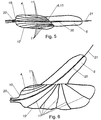
- the second preferred embodiment which in Fig. 5 and Fig. 6 is shown, it can be provided that in the interior of the first hollow body 4 a predetermined plurality of threads 11, which are connected to the wall 12 of the first hollow body 4, are arranged, and that the threads 11 in the inflated state to specify the shape of the first Hollow body 4 are stretched.
- the length, and / or thickness and / or elasticity of the individual threads 11 are predetermined such that the first hollow body 4 can spread distally more distally than intended proximally.
- the first hollow body 4 changes its shape during inflation, since the shape of the first hollow body 4 can be predetermined by the arrangement of the threads 11 loaded in the inflated state.
- first hollow body 4 in the longitudinal directions of the threads by the length, and / or thickness and / or elasticity of the individual threads 11 is limited specifiable.
- first hollow body 4 and the second hollow body 5 are shown transparent, which is why the threads 11 are shown in the interior of the first hollow body 4 as a solid line.
- the threads 11 are formed from a polymer.
- a predeterminable number of the threads 11 are each fastened with one end to a, adjacent to the second hollow body 5 part 13 of the wall 12 of the first hollow body 4.
- the first hollow body 4 in the inflated state can be well defined in its shape.
- the threads are attached only at the ends of the wall 12 of the first hollow body 4, so are arranged freely in the first hollow body 4 except for the ends.
- those threads 11, which are fastened to the other end at the distal end of the first hollow body 4 in the inflated state are longer than those threads 11, which with the other End are attached to the proximal end 10 of the first hollow body 4.
- the first hollow body 4 during distension can spread much more distally than proximally.
- the threads 11 are arranged according to a complex three-dimensional pattern, for example spider-web-like.
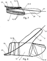
- FIGS. 7 and 8 it can be provided that on the wall 12 of the first hollow body 4 supporting elements 14 are arranged, and that the support elements 14 in the inflated state, the shape of the first hollow body 4 pretend. It can thereby be achieved that the first hollow body 4 changes its shape when inflated.
- the support members 14 may in this case be attached to the outside of the wall 12, or on the inside of the wall 12. Further, in FIGS. 7 and 8 the first hollow body 4 and the second hollow body 5 is shown transparent.
- the support elements 14 may be substantially elliptical in the slack state and substantially circular in the inflated state.
- the first hollow body 4 may be narrower in the slack state than in the inflated state.
- the main axis of the substantially elliptical-shaped support elements 14 may be substantially parallel to the longitudinal axis of the second hollow body 5, while in the inflated state, the substantially circular support elements 14 are arranged normal to the longitudinal axis of the first hollow body 4.
- the support elements 14 are designed to be flexible, so that the support elements 14 can change their shape. Furthermore, it can be provided that a support element 14 in the flaccid state consist of two flexible, elongated, and substantially parallel elements, which are connected at their end points with hinges.
- the support elements 14 may be integrally formed, wherein the hinge is formed as a location with a particularly thin cross-section is.
- the support elements 14 of a first group 15 or a second group 16 are assigned, and that in the inflated state of the second hollow body 5 adjacent part 13 of the wall 12 of the first hollow body 4 between the first group 15 and second group 16 is arranged, whereby the first hollow body 4 in the inflated state can extend both proximally and distally of the second hollow body 5.
- the support elements 14 are arranged oblong and close to each other, wherein the support members 14 are divided into two groups 15,16.
- the guide tube 20 leads through the first group 15 of support elements.
- Fig. 8 shows the third preferred embodiment in the inflated state, wherein the support members 14 are formed substantially circular. Since a circle projected laterally gives a dash, the circular support elements 14 were in Fig. 8 to the more intuitive understanding of the viewer represented as ellipses.
- the support members 14 of the first group 15 are according to Fig. 8 arranged at a constant distance from each other, while the support members 14 of the second group 16 are arranged fan-shaped after inflation, whereby the shape of the first hollow body 4 is given in the inflated state, as further deformation of the first hollow body 4 by the support members 4 is limited ,
- the first hollow body 4 is arranged in the slack state in a substantially cylindrical transport cover 17.
- the first hollow body 4 is brought to a predetermined shape of the transport casing 17 in the slack state.
- the first hollow body 4 is in this case folded together in the transport casing 17, wherein the shape of the first hollow body 4 in the flaccid but not folded state may already substantially correspond to the shape of the inflated first hollow body 4.
- the first hollow body 4 can be transported in a predetermined shape to the bifurcation in the blood vessel 3 and by removing the Transport envelope 17 are brought into the predetermined shape of the inflated state.
- first hollow body 4 and the second hollow body 5 are arranged in the slack state in the transport casing 17, whereby the device can be better moved through the blood vessel 3.
- the transport casing 17 can be made particularly removable by the transport casing 17 being arranged wegziehbar in the direction of the supply line 22.
- the transport casing 17 can be fastened to an elongate tension element, in particular a thread and / or a further wire.
- the transport casing 17 which predetermines the shape of the first hollow body 4 until it is transported to the bifurcation, can be removed at the bifurcation, whereby the hollow body 4 can be brought unhindered into the predetermined shape of the inflated state at the bifurcation.
- the transport cover 17 can then be removed from the blood vessel 3 or the patient's body, whereby any complications with the transport cover 17 can be largely prevented.
- the transport casing 17 can be arranged loosely relative to the first hollow body 4, and in particular the second hollow body 5, that is to say not be fastened. Thereby, the transport cover 17 of the first hollow body 4, and in particular the second hollow body 5, are particularly easy to remove.
- the transport casing 17 is designed for a maximum pressure of 10 bar, in particular 5 bar.
- the transport cover bursts when inflating the device, whereby the transport cover 17 can be removed in a particularly simple manner during inflation.
- the transport cover 17 predetermined breaking points 18th
- the shape of the first hollow body 4 can not only be preset in the flaccid state and in the inflated state, but also the shape of the first hollow body 4 can be controlled during the inflation.
- the predetermined breaking points 18 may be formed, for example, in that regions of the transport casing 17 are made particularly thin, or by targeted perforations of the transport casing 17, wherein many closely fitting perforations cause the transport casing to crack at lower pressure. As a result, the predetermined breaking point 18 can have a flowing course, which specifies where and at which pressure the transport sleeve 17 ruptures.
- FIG. 9 It can be seen how the first hollow body 4 and the second hollow body 5 are arranged in the slack state in the transport envelope.
- the first hollow body 4 is folded.
- the predetermined breaking point 18 of the transport casing 17 in this case faces that side which should expand more when inflated.
- the predetermined breaking point 18 is formed such that the transport sleeve 17 tears at increasing pressure, first in the region of the second hollow body 5, which faces away from the first hollow body 4, and then the crack propagates through the transport sleeve 17 to the proximal end 10 of the first hollow body 4 ,
- Fig. 10 shows an intermediate step in the inflation of the fourth preferred embodiment.
- the transport sleeve 17 is partially torn open, wherein the predetermined breaking point 18 in the region of the second hollow body 5 is already completely torn open, but in the region of the first hollow body 4 at that point, which is arranged at the intended use on the ostium 25.
- the stent 2 of the secondary branch 24 is first pushed away laterally.
- the transport casing 17 is partially secured to the first hollow body 4 and / or to the second hollow body 5, in particular with at least one predetermined crack point.
- the transport cover 17 may be attached to the, the predetermined breaking point 18 opposite side of the device. This can prevent the Transport cover 17 during transport of the device for bifurcation with respect to the first hollow body 4 and / or the second hollow body 5 twisted or twisted.
- the Sollrissstelle ie a point at which the transport sleeve 17 is attached to the first hollow body 4 and / or second hollow body 5 specifiable breakable, the transport sleeve 17 with a predetermined force from the first hollow body 4 and / or on the second hollow body 5 to be separated.
- Fig. 11 shows the fourth preferred embodiment of the device in the inflated state, wherein the transport sleeve 17 is torn open at the predetermined breaking point 18, and the inflated first hollow body 4 has its predetermined shape, whereby in the intended use those parts of the stent 2 of the secondary branch 24, which in the main branch 23 have been pushed around the ostium 25 to the inside of the stent 1 of the main branch 23 were pressed.
Landscapes
- Health & Medical Sciences (AREA)
- Engineering & Computer Science (AREA)
- Biomedical Technology (AREA)
- Cardiology (AREA)
- Oral & Maxillofacial Surgery (AREA)
- Transplantation (AREA)
- Heart & Thoracic Surgery (AREA)
- Vascular Medicine (AREA)
- Life Sciences & Earth Sciences (AREA)
- Animal Behavior & Ethology (AREA)
- General Health & Medical Sciences (AREA)
- Public Health (AREA)
- Veterinary Medicine (AREA)
- Media Introduction/Drainage Providing Device (AREA)
- Prostheses (AREA)
Description
- Die Erfindung betrifft eine Vorrichtung zur vorgebbaren Anordnung eines Stents in einem Blutgefäß gemäß dem Oberbegriff des Patentanspruches 1.
- Ein Stent ist eine scherengitterartige Gefäßstütze, welche dazu dient, Einengungen von Blutgefäßen oder anderen Lumen des Körpers dauerhaft zu erweitern. Solche Einengungen können beispielsweise krankheitsbedingt sein oder durch Ablagerungen an den Gefäßwänden hervorgerufen werden. Der Stent wird hierfür mittels eines Ballonkatheters durch einen arteriellen Zugang zu der gewünschten Stelle transportiert und dann durch ein Aufblasen dieses Ballons, daher einer Battonditatation, an der gewünschten Stelle gegen das Gefäß gepresst und damit fixiert.
- Eine große Herausforderung stellen hierbei sogenannte Bifurkationen, daher Verzweigungen der Blutgefäße dar. Bei einer Bifurkation zweigt von einem Hauptast des Blutgefäßes ein Nebenast ab. Als Fachausdruck wird für den Hauptast oft das englische Wort "main branch", und für den Nebenast das englische Wort "side branch" verwendet. Der Abgang des Nebenastes vom Hauptast wird als Ostium bezeichnet. Hierbei werden in der Regel zwei Stents gesetzt, einer im Hauptast und einer im Nebenast, wobei der Stent im Nebenast in der Regel über das Ostium hinaus in den Hauptast des Blutgefäßes ragt
- Nachteilig daran ist, dass der in den Hauptast ragende Teil des Stents des Nebenastes zu Komplikationen führen kann.
- Die
US 2008/033525 A1 beschreibt ein Kathetersystem, bei welchem zwei seriell hintereinander angeordnete Ballone vorgesehen sind. - Die
WO 97/15346 A1 - Die
EP 2 036 519 A1 und dieUS 2006/0030924 A1 beschreiben ebenfalls jeweils Vorrichtungen mit zwei nebeneinender angeordneten Ballonen. - Aus der
WO 2008/157760 A1 geht ein weiteres Ballonkathetersystem hervor. - Die
US 2005/021070 A1 beschreibt ein Kathetersystem mit einem dünnen Ballon und einem dünnen Stent, welche dazu ausgebildet sind, durch die Maschen eines, in einem Hauptast angeordneten Stents in einen Nebenast geschoben zu werden. AusWO 2009/035957 A1 ist ein Ballonkatheter bekannt mit einem Set von zwei Ballons mit unterschiedlicher Expansionsfähigkeit. Aufgabe der Erfindung ist es daher eine Vorrichtung der eingangs genannten Art anzugeben, mit welcher die genannten Nachteile vermieden werden können, mit welcher die eingesetzten Stents an die Form der Bifurkation angepasst werden können. - Erfingdungsgemäß wird dies durch die Merkmale des Patentanspruches 1 erreicht. Dadurch ergibt sich der Vorteil, dass die Einengung an der Bifurkation vollständig beseitigt werden kann. Dabei kann der Stent des Nebenast vollständig an die Gefäßwand des Hauptastes im Bereich des Ostiums angelegt werden, wodurch ein stabiler Zusammenhalt der Gefäßwand des Hauptastes mit dem Stent des Nebenastes erreicht werden kann. Weiters wird dadurch verhindert, dass Teile des Stents des Nebenastes in den Hauptast hineinragen und zu Komplikationen führen. Das vollständige Anlegen des Stents des Nebenastes an das Ostium kann mit einem Schritt erfolgen, wodurch die Zeit des medizinischen Eingriffes kurz gehalten werden kann, wodurch die Sicherheit des Patienten erhöht werden kann.
- Die Unteransprüche betreffen weitere vorteilhafte Ausgestaltungen der Erfindung.
- Ausdrücklich wird hiermit auf den Wortlaut der Ansprüche Bezug genommen, wodurch die Ansprüche an dieser Stelle durch Bezugnahme in die Beschreibung eingefügt sind und als wörtlich wiedergegeben gelten.
- Die Erfindung wird unter Bezugnahme auf die beigeschlossenen Zeichnungen, in welchen lediglich bevorzugte Ausführungsformen beispielhaft dargestellt sind, näher beschrieben. Dabei zeigt:
-
Fig. 1 eine erste bevorzugte Ausführungsform der Vorrichtung im schlaffen Zustand im Blutgefäß; -
Fig. 2 die erste bevorzugte Ausführungsform der Vorrichtung im aufgeblasenen Zustand im Blutgefäß; -
Fig. 3 die erste bevorzugte Ausführungsform der Vorrichtung im schlaffen Zustand; -
Fig. 4 die erste bevorzugte Ausführungsform der Vorrichtung im aufgeblasenen Zustand; -
Fig. 5 eine zweite bevorzugte Ausführungsform der Vorrichtung im schlaffen Zustand; -
Fig. 6 die zweite bevorzugte Ausführungsform der Vorrichtung im aufgeblasenen Zustand; -
Fig. 7 eine dritte bevorzugte Ausführungsform der Vorrichtung im schlaffen Zustand; -
Fig. 8 die dritte bevorzugte Ausführungsform der Vorrichtung im aufgeblasenen Zustand; -
Fig. 9 eine vierte bevorzugte Ausführungsform der Vorrichtung im schlaffen Zustand als Schnitt; -
Fig. 10 die vierte bevorzugte Ausführungsform der Vorrichtung im halb aufgeblasenen Zustand; und -
Fig. 11 die vierte bevorzugte Ausführungsform der Vorrichtung im aufgeblasenen Zustand. - Die
Fig. 1 bis 11 zeigen bevorzugte Ausführungsformen einer Vorrichtung zur vorgebbaren Anordnung eines Stents 2 in einem Blutgefäß 3, wobei die Vorrichtung einen ersten aufblasbaren Hohlkörper 4 und einen zweiten aufblasbaren Hohlkörper 5 aufweist, wobei - in einem schlaffen Zustand der beiden aufblasbaren Hohlkörper 4,5 - der erste Hohlkörper 4 und der zweite Hohlkörper 5 jeweils im Wesentlichen die Form eines Zylinders aufweisen. Der schlaffe Zustand der beiden aufblasbaren Hohlkörper 4,5 wird zum Zwecke der besseren Lesbarkeit in Folge lediglich als der schlaffe Zustand bezeichnet. Aufblasbar bedeutet in diesem Sinne, dass die beiden Hohlkörper 4,5 ähnlich einem Ballon Ihre Form verändern, wenn die beiden Hohlkörper 4,5 mit einem Inflationsfluid gefüllt werden. Im Wesentlichen die Form eines Zylinders aufweisend wird in diesem Zusammenhang sehr weitläufig gesehen. Ein im Wesentlichen die Form eines Zylinders aufweisender Körper hat eine längliche Form, wobei der Querschnitt durchaus komplexere Formen annehmen kann. Auch kann der Querschnitt über die Längsachse variieren, und beispielsweise zu den Enden hin kontinuierlich abnehmen. - Eine Längserstreckung des ersten Hohlkörpers 4 ist, im schlaffen Zustand, im Wesentlichen fluchtend zu einer Längserstreckung des zweiten Hohlkörpers 5 angeordnet. Im Wesentlichen fluchtend bedeutet in diesem Sinne, dass die Längserstreckung des ersten Hohlkörpers 4 und die Längserstreckung des zweiten Hohlkörpers 5 einen Winkel von bis zu 15° einschließen können. Dadurch kann die Vorrichtung gut zu der gewünschten Stelle transportiert werden, wobei die Vorrichtung bei der Bifurkation durch eine gegebenenfalls vorhandene leichte Krümmung leichter in den Nebenast 24 eingeführt und richtig positioniert werden kann.
- In einem vorgebbar aufgeblasenen Zustand der beiden Hohlkörper 4,5 weisen der erste Hohlkörper 4 und der zweite Hohlkörper 5 jeweils im Wesentlichen die Form eines Zylinders auf, wobei die Längserstreckung des zweiten Hohlkörpers 5 einen vorgebbaren Winkel zwischen 20° und 160° zur Längserstreckung des ersten Hohlkörpers 4 einnimmt. Der vorgebbar aufgeblasene Zustand der beiden Hohlkörper 4,5 wird zum Zwecke der besseren Lesbarkeit in Folge als der aufgeblasene Zustand bezeichnet. Der vorgebbare Winkel im aufgeblasenen Zustand wird zwischen dem distalen Ende des ersten Hohlkörpers 4 und dem zweiten Hohlkörper 5 gemessen. Das distale Ende des aufgeblasenen ersten Hohlkörpers 4 ist dabei jenes Ende des ersten Hohlkörpers 4, welches im vorgesehenen Einsatz im Blutgefäß 3 dem arteriellen Zugang abgewandt ist.
- Dadurch ergibt sich der Vorteil, dass die Einengung an der Bifurkation vollständig beseitigt werden kann. Dabei kann der Stent 2 des Nebenastes 24 vollständig an die Gefäßwand des Hauptastes 23 im Bereich des Ostiums 25 angelegt werden, wodurch ein stabiler Zusammenhalt der Gefäßwand des Hauptastes 23 mit dem Stent 2 des Nebenastes 24 erreicht werden kann. Weiters wird dadurch verhindert, dass Teile des Stents 2 des Nebenastes 24 in den Hauptast 23 hineinragen und zu Komplikationen führen. Das vollständige Anlegen des Stents 2 des Nebenastes 24 an das Ostium 25 kann mit einem Schritt erfolgen, wodurch die Zeit des medizinischen Eingriffes kurz gehalten werden kann, wodurch die Sicherheit des Patienten erhöht werden kann.
- Der erste Hohlkörper 4 und der zweite Hohlkörper 5 können insbesondere aus einem für Ballonkatheter geeignetem Material ausgebildet sein. Solche Materialien können beispielsweise thermoplastische Polymere, Polyethylene, Co-Polymere oder Nylon sein, um nur einige zu nennen.
- Besonders bevorzugt kann vorgesehen sein, dass der erste Hohlkörper 4 und/oder der zweite Hohlkörper 5 aus einem non-compliant Material ausgebildet sind. Insbesondere kann vorgesehen sein, dass eine Wand 12 des ersten Hohlkörpers 4 und/oder eine Wand des zweiten Hohlkörpers 5 aus einem non-compliant Material ausgebildet sind. Ein Ballonkatheter aus einem non-compliant Material, auch oft als non-compliant Ballonkatheter bezeichnet, dehnt sich zunächst bis zu einer vorgegebenen Größe aus. Nach Erreichen der vorgegebenen Größe verändert sich der Durchmesser mit zunehmenden Druck nur geringfügig. Dadurch kann die Gefahr einer Überdehnung des Blutgefäßes 3 gering gehalten werden.
- Besonders bevorzugt kann vorgesehen sein, dass der zweite Hohlkörper 5 im Wesentlichen unmittelbar angrenzend an den ersten Hohlkörper 4 angeordnet ist. Dadurch kann eine besonders kompakte Form der Vorrichtung erzielt werden, welche leicht einzuführen und zu bedienen ist. Weiters kann dadurch eine gute Kraftwirkung auf den Stent 2 des Nebenastes 24 im Bereich des Ostiums 25 erzielt werden.
- Weiters kann bevorzugt vorgesehen sein, dass - im schlaffen Zustand - eine Stirnseite 6 des zweiten Hohlkörpers 5 an einer Stirnseite des ersten Hohlkörpers 4 angrenzt. Hierbei ist zu beachten, dass der erste Hohlkörper 4 beim Aufblasen seine Form verändern kann, und daher die Stirnseite des ersten Hohlkörpers 4 im schlaffen Zustand nicht zwangsweise die Stirnseite des ersten Hohlkörpers 4 im aufgeblasenen Zustand sein muss. Durch diese Form und/oder Anordnung im schlaffen Zustand kann die Vorrichtung besonders gut im schlaffen Zustand durch die Blutgefäße 3 bewegt werden.
- Besonders bevorzugt kann vorgesehen sein, dass an der Vorrichtung eine Markierung angeordnet ist, insbesondere im Bereich der dem ersten Hohlkörper 4 zugewandten Stirnseite des zweiten Hohlkörpers 5, und welche Markierung insbesondere röntgensichtbar ist. Röntgensichtbar bedeutet in diesem Zusammenhang, dass die Markierung also Röntgenbild einen guten Kontrast zum umgebenden Bereich aufweist. Dadurch kann die behandelnde Person die Vorrichtung vor dem Aufblasen gezielt positionieren.
- Insbesondere kann vorgesehen sein, dass - im aufgeblasenen Zustand - der zweite Hohlkörper 5 an einer Mantelfläche des ersten Hohlkörpers 4 angeordnet ist. Dadurch steht der zweite Hohlkörper 5 im aufgeblasenen Zustand von dem ersten Hohlkörper 4 ab, wodurch die Vorrichtung im aufgeblasenen Zustand sich der Form der Bifurkation anpassen kann, wodurch auch der Stent 2 gut an dem Blutgefäß 3 im Bereich der Bifurkation befestigt werden kann.
- Besonders bevorzugt kann weiters vorgesehen sein, dass - im aufgeblasenen Zustand - der zweite Hohlkörper 5 beidseitig in Längserstreckung des ersten Hohlkörpers 4 von der Mantelfläche des ersten Hohlkörpers 4 umgeben ist. Hierbei sieht die Vorrichtung im aufgeblasenen Zustand im Querschnitt wie ein schiefes T aus, wobei in einer Bifurkation der zweite Hohlkörper 5 im Nebenast 24 sitzt, und der erste Hohlkörper 4 sich im Bereich des Ostiums 25 im Hauptast 23 befindet, und den Stent 2 des Nebenastes 24 im Bereich des Hauptastes 23 an die Gefäßwand des Blutgefäßes 3 drückt. Hierbei erstreckt sich, von dem arteriellen Zugang des Katheters aus gesehen, der erste Hohlkörper 4 sowohl distal als auch proximal vom Ostium 25, wodurch der Stent 2 besonders gut an die Form der Bifurkation angepasst werden können.
- Insbesondere kann vorgesehen sein, dass - im aufgeblasenen Zustand - der zweite Hohlkörper 5 im Wesentlichen in der Mitte der Längserstreckung der Mantelfläche des ersten Hohlkörpers 4 angeordnet ist.
- Bei dem vorgesehenen Einsatz der Vorrichtung in einer Bifurkation kann insbesondere vorgesehen sein, dass im schlaffen Zustand der zweite Hohlkörper 5 im Nebenast 24 angeordnet ist, und der erste Hohlkörper im Wesentlichen fluchtend zum zweiten Hohlkörper 5 im proximalen Teil des Hauptastes 23 angeordnet ist, und dass die Form des ersten Hohlkörpers beim Aufblasen derart veränderbar ist, dass sich der erste Hohlkörper beim Aufblasen distal wesentlich stärker ausbreitet als proximal.
- Bevorzugt kann vorgesehen sein, dass ein Durchmesser des ersten Hohlkörpers 4 im aufgeblasenen Zustand größer ist, als ein Durchmesser des zweiten Hohlkörpers 5 im aufgeblasenen Zustand. Da beide Hohlkörper 4,5 lediglich im Wesentlichen die Form eines Zylinders aufweisen und daher recht komplexe Formen annehmen können, ist in diesem Sinne der Durchmesser eines der beiden Hohlkörper 4, 5 der Durchmesser des Umkreises des Querschnitts normal zur Längsachse, welcher in der Mitte der Längsachse angeordnet ist, wobei der gegenständliche Hohlkörper 4,5 mit einem Überdruck von 5 bar außerhalb eines Körpers aufgeblasen ist. Dadurch entspricht die aufgeblasene Vorrichtung mehr der Form der Bifurkation.
- Insbesondere kann vorgesehen sein, dass der Durchmesser der beiden Hohlkörper 4, 5 zwischen 1 mm und 10 mm, insbesondere zwischen 2 mm und 5 mm beträgt.
- Besonders bevorzugt kann vorgesehen sein, dass der Durchmesser des zweiten Hohlkörpers 5 im aufgeblasenen Zustand mit zunehmendem Abstand vom ersten Hohlkörper 4 stetig abnimmt, daher, dass der zweite Hohlkörper 5 im Wesentlichen eine konische Form aufweist. Dadurch kann die Vorrichtung leichter in den Nebenast 24 eingeführt werden.
- Bevorzugt kann weiters vorgesehen sein, dass der erste Hohlkörper 4 und/oder der zweite Hohlkörper 5 für einen Überdruck von 10 bar, vorzugsweise 20 bar, insbesondere 30 bar, ausgebildet ist. Dadurch kann eine Verengung des Blutgefäßes 3 gut aufgeweitet, und der Stent 2 zuverlässig fixiert werden.
- Besonders bevorzugt kann vorgesehen sein, dass an einem proximalen Ende 10 des ersten Hohlkörpers 4 im aufgeblasenen Zustand eine Zuleitung 22 angeordnet ist, über welche das Inflationsfluid in die beiden Hohlkörper 4,5 einleitbar ist. Das proximale Ende des aufgeblasenen ersten Hohlkörpers 4 ist jenes Ende, welches dem arteriellen Zugang zugewandte ist. Das Inflationsfluid kann beispielsweise eine NaCl Lösung mit einem Kontrastmittel sein.
- Hierbei kann vorgesehen sein, dass der Hohlraum des ersten Hohlkörpers 4 mit dem Hohlraum des zweiten Hohlkörpers 5 verbunden ist, so dass beim Aufblasen sowohl im ersten Hohlkörper 4 als auch im zweiten Hohlkörper 5 der gleiche Druck vorherrscht.
- Insbesondere kann vorgesehen sein, dass der zweite Hohlkörper 5 derart ausgebildet ist, dass sich der zweite Hohlkörper 5 vor dem ersten Hohlkörper 4 ausdehnt. Dies kann vorzugsweise dadurch erfolgen, dass der erste Hohlkörper 4 und der zweite Hohlkörper 5 unterschiedlich dehnbar sind. Dadurch kann die Vorrichtung zuverlässig im Nebenast 24 verankert werden, bevor der Stent 2 durch den ersten Hohlkörper 4 verformt wird.
- Alternativ kann vorgesehen sein, dass der erste Hohlkörper 4 und der zweite Hohlkörper 5 getrennt voneinander aufblasbar sind. Dies kann beispielsweise dadurch erfolgen, dass an der Zuleitung 22 eine Nebenleitung angeordnet ist, welche dazu ausgebildet ist, lediglich den zweiten Hohlkörper 5 aufzublasen.
- Dadurch kann beispielsweise bei der vorgesehenen Verwendung zuerst der zweite Hohlkörper 5 im Nebenast 24 aufgeblasen werden, um die Vorrichtung zu fixieren, und erst in einem zweiten Schritt der erste Hohlkörper 4 aufgeblasen werden, um den Stent 2 an die Bifurkation anzupassen.
- In der Regel werden Führungsdrähte 21 verwendet, um Ballonkatheter zur vorgesehenen Stelle zu transportieren und/oder zu leiten. Besonders bevorzugt kann daher vorgesehen sein, dass durch den ersten Hohlkörper 4 und den zweiten Hohlkörper 5 ein Führungsschlauch 20 zur Führung eines Führungsdrahtes 21 angeordnet ist. Hierbei kann der Führungsdraht 21 im Führungsschlauch 20, welcher auch als Drahtkanal bezeichnet werden kann, bewegbar angeordnet werden. Bei der vorgesehenen Verwendung wird der Führungsdraht 21 in dem Nebenast 24 angeordnet und in weiterer Folge der zweite Hohlkörper 5 entlang des Führungsdrahtes 21 ebenfalls im Nebenast 24 angeordnet. Dadurch kann die Vorrichtung für die vorgesehene Verwendung gut in der Bifurkation angeordnet werden. Dadurch, dass der Führungsschlauch 20 innerhalb der beiden Hohlkörper 4, 5 angeordnet ist, kann die Vorrichtung besonders zuverlässig entlang des Führungsdrahtes 21 bewegt werden.
- Gemäß einer weiteren, nicht dargestellten Ausführungsform der gegenständlichen Erfindung kann vorgesehen sein, dass wenigstens ein weiterer Führungsschlauch bzw. Drahtkanal vorgesehen ist, bzw. an dem Hohlkörper bzw. an dem ersten Führungsschlauch 20 befestigt ist. Dadurch kann ein zweiter Führungsdraht verwendet werden, um den Hohlkörper einfacher auszurichten. Dadurch kann besonders einfach mittels eines weiteren Drahtes der erste Hohlkörper 4 derart entlang seiner Längserstreckung gedreht werden, dass der zweite Hohlkörper 5 sich beim Aufblasen in die angestrebte Richtung erstreckt.
- In
Fig. 1 bis Fig. 11 sind die Proportionen der Vorrichtung zur besseren Darstellung der Merkmale verzehrt dargestellt. Insbesondere bezüglich dem schlaffen Zustand ist da Verhältnis Länge der Vorrichtung zu Durchmesser der Vorrichtung wesentlich kleiner dargestellt als in der Realität zu erwarten. -
Fig. 1 zeigt die erste bevorzugte Ausführungsform der Vorrichtung im schlaffen Zustand in einer vorgesehenen Position innerhalb einer Bifurkation eines Blutgefäßes 3. Die Bifurkation inFig. 1 besteht aus einem geraden Hauptast 23, von welchem in einem Winkel von ca. 45° ein Nebenast 24 abzweigt. Im Nebenast 24 ist bereits der Stent 2 angeordnet. Zum Zwecke der Übersichtlichkeit wird der Stent 2 inFig. 1 und Fig. 2 nur als Umriss mit gezackten Enden dargestellt. Ein Führungsdraht 21 führt von dem Hauptast 23 durch das Ostium 25 in den Nebenast 24, wobei am Führungsdraht 21 die erste bevorzugte Ausführungsform der Vorrichtung bewegbar angeordnet ist. - In
Fig. 1 ist der zweite Hohlkörper 5 innerhalb des Stents 2 des Nebenastes 24 angeordnet, wobei die Stirnseite 6 des zweiten Hohlkörpers 5, welche dem ersten Hohlkörper 4 zugewandt ist, sich auf der Höhe des Ostiums 25 befindet und mit einem Winkel von 45° schräg zur Längsachse des zweiten Hohlkörpers 5 orientiert ist. Der erste Hohlkörper 4 ist unmittelbar angrenzend an den zweiten Hohlkörper 5 angeordnet, wobei sich der erste Hohlkörper 4 bereichsweise innerhalb des Stents 2 des Nebenastes 24 befindet. -
Fig. 2 zeigt die erste bevorzugte Ausführungsform der Vorrichtung im aufgeblasenen Zustand in einer vorgesehenen Position innerhalb des Blutgefäßes 3 ausFig. 1 . Der aufgeblasene zweite Hohlkörper 5 liegt innen an dem Stent 2 des Nebenastes 24 an, womit die Position der Vorrichtung gegenüber der Bifurkation verankert ist. Der aufgeblasene erste Hohlkörper 4 weist nun im Wesentlichen die Form eines Zylinders auf, wobei die Längsachse des aufgeblasenen ersten Hohlkörpers 4 mit der Längsachse des Hauptastes 23 fluchtet. - Gemäß
Fig. 2 schließen die Längsachse des aufgeblasenen zweiten Hohlkörpers 5 und die Längsachse des aufgeblasenen ersten Hohlkörpers 4 einen Winkel von 45° ein. Weiters grenzt der zweite Hohlkörper 5 an den mittleren Bereich des ersten Hohlkörpers 4 an. - Der erste Hohlkörper 4 hat sich beim Aufblasen distal viel stärker ausgebreitet als proximal. Jene Bereiche des Stents 2 des Nebenastes 24, in welchen der erste Hohlkörper 4 im schlaffen Zustand angeordnet war, sind im aufgeblasenen Zustand durch den ersten Hohlkörper 4 an die Innenseite der Gefäßwand des Hauptastes 23 gedrückt, wie durch den Pfeil in
Fig. 2 angedeutet, wodurch die Form des Stents 2 an die Form der Bifurkation des Blutgefäßes 3 angepasst ist, und kein Teil des Stents 2 in das Blutgefäß 3 ragt. - Um den ersten Hohlkörper 4 inhomogen aufzublasen, daher, dass der erste Hohlkörper 4 im schlaffem Zustand eine andere Form und Orientierung aufweist als im aufgeblasenem Zustand, kann wie in
Fig. 3 und Fig. 4 dargestellt, bevorzugt vorgesehen sein, dass die Wand 12 des ersten Hohlkörpers 4 aus wenigstens einem ersten Bereich 7 und einem zweiten Bereich 8 besteht, und dass der erste Bereich 7 und der zweite Bereich 8 unterschiedlich dehnbar sind. Unterschiedlich dehnbar bedeutet in diesem Zusammenhang, dass sich der erste Bereich 7 und der zweite Bereich 8 bei sich verändernden Druck im ersten Hohlkörper 4 unterschiedlich stark ausdehnen, daher deren Fläche verändern. Dadurch kann der erste Hohlkörper 4 beim Aufblasen seine Form verändern. - Diese unterschiedliche Dehnbarkeit kann beispielsweise dadurch erreicht werden, dass der erste Bereich 7 und der zweite Bereich 8 unterschiedliche Wanddicken aufweisen. Hierbei kann beispielsweise vorgesehen sein, dass der erste Bereich 7 eine erste Wanddicke aufweist, und der zweite Bereich 8 eine zweite Wanddicke aufweist, wobei die erste Wanddicke größer ist als die zweite Wanddicke. Dadurch dehnt sich der zweite Bereich 8 stärker mit zunehmendem Druck aus als der erste Bereich 7, wodurch der erste Hohlkörper 4 beim Aufblasen seine Form verändert.
- Alternativ kann diese unterschiedliche Dehnbarkeit dadurch erreicht werden, dass der erste Bereich 7 und der zweite Bereich 8 unterschiedlich elastisch sind. Hierbei bezieht sich die unterschiedliche Elastizität auf unterschiedliche E-Module der verwendeten Materialien. Beispielsweise kann hierfür der erste Hohlkörper 4 aus unterschiedlichen Materialien gefertigt sein. Alternativ kann aber auch vorgesehen sein, dass der erste Hohlkörper 4 aus einem Material gefertigt ist, dessen mechanische Eigenschaften in einem weiteren Fertigungsschritt bereichsweise gezielt verändert werden, beispielsweise durch eine Behandlung mit Chemikalien, durch äußere Bestrahlung, oder Einprägen einer Oberflächestruktur. Jene Materialen, aus denen der erste Hohlkörper 4 bestehen kann, können mitunter sehr komplexe Dehnungskurven aufweisen. Hierbei kann unter unterschiedlich elastisch auch verstanden werden, dass sich ein Bereich beim Aufblasen am Anfang stärker ausdehnt als ein anderer Bereich, im Endeffekt aber beide Bereiche 7,8 gleich stark ausgedehnt haben.
- Weiters kann vorgesehen sein, dass die Übergänge der unterschiedlich dehnbaren Bereiche 7,8 fließend sind, und nicht abrupt.
- Bezüglich der Anordnung der Bereiche 7,8 kann besonders bevorzugt vorgesehen sein, dass im aufgeblasenen Zustand der erste Bereich 7 zwischen dem proximalen Ende 10 des ersten Hohlkörpers 4 und dem zweiten Hohlkörper 5 angeordnet ist, und dass der zweite Bereich 8 dehnbarer ist als der erste Bereich 7. Dadurch dehnt sich der proximale Bereich des ersten Hohlkörpers 4 weniger stark aus als der restliche Bereich.
- Gemäß
Fig. 3 und Fig. 4 kann vorgesehen sein, dass im aufgeblasenen Zustand am distalen Ende des ersten Hohlkörpers 4 ein dritter Bereich 9 angeordnet ist, welcher dritter Bereich 9 dehnbarer ist als der erste Bereich 7 oder der zweite Bereich 8. Dadurch kann sich der erste Hohlkörper 4 beim Aufblasen in die distale Richtung stark ausweiten, wodurch der erste Hohlkörper 4 gut von der ursprünglichen Form im schlaffen Zustand in den Hauptast 23 ausdehnen kann. - Um zu verhindern, dass der Stent 2 des Nebenastes 24 beim Aufblasen den ersten Hohlkörper 4 beschädigt, kann vorgesehen sein, dass in einem dem ersten Hohlkörper 4 zugewandten Bereich des zweiten Hohlkörpers 5 ein Schutzlappen 19 angeordnet ist. Dieser Schutzlappen 19 kann insbesondere aus einem widerstandsfähigeren Material als der erste Hohlkörper 4 ausgebildet sein.
- Gemäß der ersten bevorzugten Ausführungsform in
Fig. 3 und Fig. 4 kann vorgesehen sein, dass der Schutzlappen 19 schürzenartig um die Stirnseite 6 des zweiten Hohlkörpers 5, welche an den ersten Hohlkörper 4 angrenzt, befestigt ist, und an jener Seite des ersten Hohlkörpers 4 angeordnet ist, welche sich beim Aufblasen in Richtung des zweiten Hohlkörpers 5 bewegt. Dadurch kann jene Stelle des ersten Hohlkörpers 4 effektiv geschützt werden, welche den Stent 2 des Nebenastes 24 am meisten verbiegt. - Dass die Vorrichtung, und insbesondere der erste Hohlkörper 4, beim Aufblasen vorgebbar die Form verändert, kann auch auf alternative Weise erreicht werden. Diese alternativen Ausführungsformen können dabei alleine das gewünschte Ziel erreichen, aber auch eine Kombination dieser diversen Ausführungsformen ist möglich.
- Gemäß der zweiten bevorzugten Ausführungsform, welche in
Fig. 5 und Fig. 6 dargestellt ist, kann vorgesehen sein, dass im Inneren des ersten Hohlkörpers 4 eine vorgebbare Mehrzahl an Fäden 11, welche mit der Wand 12 des ersten Hohlkörpers 4 verbunden sind, angeordnet sind, und dass die Fäden 11 im aufgeblasenen Zustand zur Vorgabe der Form des ersten Hohlkörpers 4 gespannt sind. Hierbei wird die Länge, und/oder Dicke und/oder Elastizität der einzelnen Fäden 11 derart vorgegeben, dass sich der erste Hohlkörper 4 bei der vorgesehenen Verwendung sich distal stärker ausbreiten kann als proximal. Dadurch kann erreicht werden, dass der erste Hohlkörper 4 beim Aufblasen seine Form vorgebbar verändert, da durch die Anordnung der im aufgeblasenen Zustand zugbelasteten Fäden 11 die Form des ersten Hohlkörpers 4 vorgegeben werden kann. Hierbei wird eine weitere Ausdehnung des ersten Hohlkörpers 4 in die Längsrichtungen der Fäden durch die Länge, und/oder Dicke und/oder Elastizität der einzelnen Fäden 11 vorgebbar begrenzt. InFig. 5 und Fig. 6 sind der erste Hohlkörper 4 und der zweite Hohlkörper 5 durchsichtig dargestellt, weshalb die Fäden 11 im Inneren des ersten Hohlkörpers 4 als durchgezogene Linie dargestellt sind. - Insbesondere kann vorgesehen sein, dass die Fäden 11 aus einem Polymer ausgebildet sind.
- Gemäß der zweiten bevorzugten Ausführungsform kann vorgesehen sein, dass eine vorgebbare Anzahl der Fäden 11 jeweils mit einem Ende an einem, an den zweiten Hohlkörper 5 angrenzenden Teil 13 der Wand 12 des ersten Hohlkörpers 4 befestigt sind. Dadurch lässt sich der erste Hohlkörper 4 im aufgeblasenen Zustand gut in seiner Form vorgeben.
- Insbesondere kann dabei vorgesehen sein, dass die Fäden lediglich an den Enden an der Wand 12 des ersten Hohlkörpers 4 befestigt sind, also bis auf die Enden frei im ersten Hohlkörper 4 angeordnet sind.
- Hierbei kann insbesondere vorgesehen sein, dass jene Fäden 11, welche mit dem anderen Ende am distalen Ende des ersten Hohlkörpers 4 befestigt sind im aufgeblasenen Zustand länger sind als jene Fäden 11, welche mit dem anderen Ende am proximalen Ende 10 des ersten Hohlkörpers 4 befestigt sind. Dadurch kann sich der erste Hohlkörper 4 beim Aufblasen distal viel mehr ausbreiten als proximal.
- Alternativ kann vorgesehen sein, dass die Fäden 11 nach einem komplexen dreidimensionalen Muster, beispielsweise spinnennetzartig, angeordnet sind.
- Gemäß einer dritten Ausführungsform, welche in
Fig. 7 und Fig. 8 dargestellt ist, kann vorgesehen sein, dass an der Wand 12 des ersten Hohlkörpers 4 Stützelemente 14 angeordnet sind, und dass die Stützelemente 14 im aufgeblasenen Zustand die Form des ersten Hohlkörpers 4 vorgeben. Dadurch kann erreicht werden, dass der erste Hohlkörper 4 beim Aufblasen seine Form vorgebbar verändert. - Die Stützelemente 14 können hierbei an der Außenseite der Wand 12 befestigt sein, oder an der Innenseite der Wand 12. Weiters wird in
Fig. 7 und Fig. 8 wird der erste Hohlkörper 4 und der zweite Hohlkörper 5 durchsichtig dargestellt. - Insbesondere kann vorgesehen sein, dass die Stützelemente 14 im schlaffen Zustand im Wesentlichen elliptisch und im aufgeblasenen Zustand im Wesentlichen kreisförmig sind. Dadurch kann der erste Hohlkörper 4 im schlaffem Zustand schmaler sein als im aufgeblasenen Zustand.
- Im schlaffen Zustand kann insbesondere die Hauptachse der im Wesentlichen elliptisch-förmigen Stützelemente 14 im Wesentlichen parallel zur Längsachse des zweiten Hohlkörpers 5 sein, während im aufgeblasenen Zustand die im Wesentlichen kreisförmigen Stützelemente 14 normal zur Längsachse des ersten Hohlkörpers 4 angeordnet sind.
- Insbesondere kann vorgesehen sein dass die Stützelemente 14 flexibel ausgebildet sind, sodass die Stützelemente 14 deren Form verändern können. Weiters kann vorgesehen sein, dass ein Stützelement 14 im schlaffen Zustand aus zwei flexiblen, länglichen, und im Wesentlichen parallelen Elementen bestehen, welche an ihren Endpunkten mit Scharnieren verbunden sind.
- Dabei können bevorzugt die Stützelemente 14 einstückig ausgebildet sein, wobei das Scharnier als eine Stelle mit einem besonders dünnen Querschnitt ausgebildet ist.
- Besonders bevorzugt kann vorgesehen sein, dass die Stützelemente 14 einer ersten Gruppe 15 oder einer zweiten Gruppe 16 zugeteilt sind, und dass im aufgeblasenen Zustand der an dem zweiten Hohlkörper 5 angrenzender Teil 13 der Wand 12 des ersten Hohlkörpers 4 zwischen der ersten Gruppe 15 und der zweiten Gruppe 16 angeordnet ist, wodurch sich der erste Hohlkörper 4 im aufgeblasenen Zustand sowohl proximal als auch distal vom zweiten Hohlkörper 5 erstrecken kann.
- Im schlaffen Zustand der dritten bevorzugten Ausführungsform, welche in
Fig. 7 dargestellt ist, sind die Stützelemente 14 länglich und nah beieinander angeordnet, wobei die Stützelemente 14 in zwei Gruppen 15,16 unterteilt sind. Der Führungsschlauch 20 führt hierbei durch die erste Gruppe 15 von Stützelementen. -
Fig. 8 zeigt die dritte bevorzugte Ausführungsform im aufgeblasenen Zustand, wobei die Stützelemente 14 im Wesentlichen kreisförmig geformt sind. Da eine Kreis seitlich projiziert einen Strich ergibt, wurden die kreisförmigen Stützelemente 14 inFig. 8 zum intuitiveren Verständnis des Betrachters als Ellipsen dargestellt. Die Stützelemente 14 der ersten Gruppe 15 sind gemäßFig. 8 in einem gleichbleibenden Abstand zueinander angeordnet, während die Stützelemente 14 der zweiten Gruppe 16 nach dem Aufblasen fächerartig ausgebreitet angeordnet sind, wodurch die Form des ersten Hohlkörpers 4 im aufgeblasenen Zustand vorgegeben ist, da ein weiteres Verformen des ersten Hohlkörpers 4 durch die Stützelemente 4 begrenz ist. - Gemäß der vierten bevorzugten Ausführungsform der Vorrichtung, welche in
Fig. 9 bis Fig. 11 dargestellt ist, kann vorgesehen sein, dass der erste Hohlkörper 4 im schlaffen Zustand in einer im Wesentlichen zylinderförmigen Transporthülle 17 angeordnet ist. Dadurch wird der erste Hohlkörper 4 im schlaffen Zustand in eine von der Transporthülle 17 vorgegebene Form gebracht. Der erste Hohlkörper 4 befindet ist hierbei in der Transporthülle 17 zusammengefaltet, wobei die Form des ersten Hohlkörpers 4 im schlaffen aber nicht-zusammengefalteten Zustand bereits im Wesentlichen der Form des aufgeblasenen ersten Hohlkörpers 4 entsprechen kann. Dadurch kann der erste Hohlkörper 4 in einer vorgegebenen Form zur Bifurkation im Blutgefäß 3 transportiert werden und durch Entfernen der Transporthülle 17 in die vorgegebene Form des aufgeblasenen Zustandes gebracht werden. - Insbesondere kann vorgesehen sein, dass der erste Hohlkörper 4 und der zweite Hohlkörper 5 im schlaffen Zustand in der Transporthülle 17 angeordnet sind, wodurch sich die Vorrichtung besser durch das Blutgefäß 3 bewegen lässt.
- Die Transporthülle 17 kann besonders bevorzugt dadurch entfernbar ausgebildet werden, indem die Transporthülle 17 in Richtung der Zuleitung 22 wegziehbar angeordnet ist.
- Um die Transporthülle 17 von dem ersten Hohlkörper 4, und insbesondere dem zweiten Hohlkörper 5, wegzuziehen, insbesondere um die Transporthülle 17 separat von dem ersten Hohlkörper 4 und dem zweiten Hohlkörper 5 aus dem Blutgefäß 3 oder dem Körper des Patienten zu entfernen kann bevorzugt vorgesehen sein, dass die Transporthülle 17 an einem längliches Zugelement, insbesondere einem Faden und/oder einem weiteren Draht, befestigbar ausgebildet ist. Dadurch kann die Transporthülle 17, welche die Form des ersten Hohlkörpers 4 bis zum Transport zur Bifurkation vorgibt, bei der Bifurkation entfernt werden, wodurch der Hohlkörper 4 bei der Bifurkation ungehindert in die vorgegebene Form des aufgeblasenen Zustandes gebracht werden kann. Durch das Zugelement kann dann die Transporthülle 17 aus dem Blutgefäß 3 oder dem Körper des Patienten entfernt werden, wodurch etwaige Komplikationen mit der Transporthülle 17 weitgehend verhindert werden können.
- Insbesondere kann die Transporthülle 17 gegenüber dem ersten Hohlkörper 4, und insbesondere dem zweiten Hohlkörper 5, lose angeordnet sein, also nicht befestigt sein. Dadurch kann die Transporthülle 17 von dem ersten Hohlkörper 4, und insbesondere dem zweiten Hohlkörper 5, besonders einfach entfernt werden.
- Besonders bevorzugt kann vorgesehen sein, dass die Transporthülle 17 für einen maximalen Druck von 10 bar, insbesondere 5 bar, ausgebildet ist. Dadurch platzt die Transporthülle beim Aufblasen der Vorrichtung, wodurch die Transporthülle 17 auf eine besonders einfache Art und Weise beim Aufblasen entfernt werden kann.
- Insbesondere kann vorgesehen sein, dass die Transporthülle 17 Sollbruchstellen 18 aufweist, zum vorgebbaren Aufreisen der Transporthülle 17 beim Aufblasen des ersten Hohlkörpers 4. Dadurch kann die Form des ersten Hohlkörpers 4 nicht nur im schlaffen Zustand und im aufgeblasenen Zustand vorgegeben werden, sondern auch noch die Form des ersten Hohlkörpers 4 während des Aufblasens kontrolliert werden.
- Die Sollbruchstellen 18 kann beispielsweise dadurch ausgebildet sein, dass Bereiche der Transporthülle 17 besonders dünn ausgebildet sind, oder durch gezielte Perforationen der Transporthülle 17, wobei viele eng anliegende Perforationen die Transporthülle bei geringerem Druck reißen lassen. Dadurch kann die Sollbruchstelle 18 einen fließenden Verlauf haben, welcher vorgibt, wo und bei welchem Druck die Transporthülle 17 aufreißt.
- In
Fig. 9 ist zu sehen, wie der erste Hohlkörper 4 und der zweite Hohlkörper 5 im schlaffen Zustand in der Transporthülle angeordnet sind. Hierbei ist der erste Hohlkörper 4 zusammengefaltet. Die Sollbruchstelle 18 der Transporthülle 17 ist hierbei jener Seite zugewandt, welche sich bei Aufblasen stärker ausdehnen soll. Hierbei ist die Sollbruchstelle 18 derart ausgebildet, dass die Transporthülle 17 bei ansteigendem Druck zunächst im Bereich des zweiten Hohlkörpers 5 aufreißt, welcher dem ersten Hohlkörper 4 abgewandt ist, und sich dann der Riss durch die Transporthülle 17 zum proximalen Ende 10 des ersten Hohlkörpers 4 ausbreitet. -
Fig. 10 zeigt einen Zwischenschritt beim Aufblasen der vierten bevorzugten Ausführungsform. Hierbei ist die Transporthülle 17 teilweise aufgerissen, wobei die Sollbruchstelle 18 im Bereich des zweiten Hohlkörpers 5 bereits gänzlich aufgerissen ist, aber im Bereich des ersten Hohlkörpers 4 an jener Stelle, welche bei der vorgesehenen Verwendung am Ostium 25 angeordnet ist. Dadurch wird bei der vorgesehenen Verwendung der Stent 2 des Nebenastes 24 zunächst seitlich weggedrückt. - Bevorzugt kann weiters vorgesehen sein, dass die Transporthülle 17 bereichsweise an dem ersten Hohlkörper 4 und/oder an dem zweiten Hohlkörper 5, insbesondere mit wenigstens einer Sollrissstelle, befestigt ist. Beispielsweise kann die Transporthülle 17 an der, der Sollbruchstelle 18 gegenüberliegenden Seite der Vorrichtung befestigt sein. Dadurch kann verhindert werden, dass sich die Transporthülle 17 beim Transport der Vorrichtung zur Bifurkation gegenüber dem ersten Hohlkörper 4 und/oder dem zweiten Hohlkörper 5 verdreht oder verdrillt. Durch die Sollrissstelle, also eine Stelle an welcher die Transporthülle 17 an dem ersten Hohlkörper 4 und/oder an dem zweiten Hohlkörper 5 vorgebbar reißbar befestigt ist, kann die Transporthülle 17 mit einer vorgebbaren Kraft von dem ersten Hohlkörper 4 und/oder an dem zweiten Hohlkörper 5 getrennt werden.
-
Fig. 11 zeigt die vierte bevorzugte Ausführungsform der Vorrichtung im aufgeblasenen Zustand, wobei die Transporthülle 17 an der Sollbruchstelle 18 gänzlich aufgerissen ist, und der aufgeblasene erste Hohlkörper 4 seine vorgegebene Form hat, wodurch bei der vorgesehenen Verwendung jene Teile des Stents 2 des Nebenastes 24, welche in den Hauptast 23 hineingeragt haben, um das Ostium 25 herum an die Innenseite des Stents 1 des Hauptastes 23 gepresst wurden.
Claims (13)
- Vorrichtung zur vorgebbaren Anordnung eines Stents (2) in einem Blutgefäß (3), wobei die Vorrichtung einen ersten aufblasbaren Hohlkörper (4) und einen zweiten aufblasbaren Hohlkörper (5) aufweist, wobei - in einem schlaffen Zustand der beiden aufblasbaren Hohlkörper (4,5) - der erste Hohlkörper (4) und der zweite Hohlkörper (5) jeweils im Wesentlichen die Form eines Zylinders aufweisen, und wobei eine Längserstreckung des ersten Hohlkörpers (4) im Wesentlichen fluchtend zu einer Längserstreckung des zweiten Hohlkörpers (5) angeordnet ist, wobei - im schlaffen Zustand - eine Stirnseite (6) des zweiten Hohlkörpers (5) an einer Stirnseite des ersten Hohlkörpers (4) angrenzt, dadurch gekennzeichnet, dass die Vorrichtung derart ausgebildet ist, dass die Vorrichtung beim Aufblasen vorgebbar die Form verändert, dass - in einem aufgeblasenen Zustand der beiden Hohlkörper (4,5) - der erste Hohlkörper (4) und der zweite Hohlkörper (5) jeweils im Wesentlichen die Form eines Zylinders aufweisen, dass die Längserstreckung des zweiten Hohlkörpers (5) einen vorgebbaren Winkel zwischen 20° und 160° zur Längserstreckung des ersten Hohlkörpers (4) einnimmt, und dass - im aufgeblasenen Zustand - der zweite Hohlkörper (5) an einer Mantelfläche des ersten Hohlkörpers (4) angeordnet ist.
- Vorrichtung nach Anspruch 1, dadurch gekennzeichnet, dass der zweite Hohlkörper (5) im Wesentlichen unmittelbar angrenzend an den ersten Hohlkörper (4) angeordnet ist.
- Vorrichtung nach Anspruch 1 oder 2, dadurch gekennzeichnet, dass - im aufgeblasenen Zustand - der zweite Hohlkörper (5) beidseitig in Längserstreckung des ersten Hohlkörpers (4) von der Mantelfläche des ersten Hohlkörpers (4) umgeben ist.
- Vorrichtung nach einem der Ansprüche 1 bis 3, dadurch gekennzeichnet, dass eine Wand (12) des ersten Hohlkörpers (4) aus wenigstens einem ersten Bereich (7) und einem zweiten Bereich (8) besteht, und dass der erste Bereich (7) und der zweite Bereich (8) unterschiedlich dehnbar sind.
- Vorrichtung nach Anspruch 4, dadurch gekennzeichnet, dass der erste (7) Bereich und der zweite Bereich (8) unterschiedliche Wanddicken aufweisen, oder dass der erste Bereich (7) und der zweite Bereich (8) unterschiedlich elastisch sind.
- Vorrichtung nach einem der Ansprüche 4 oder 5, dadurch gekennzeichnet, dass im aufgeblasenen Zustand der erste Bereich (7) zwischen einem proximalen Ende (10) des ersten Hohlkörpers (4) und dem zweiten Hohlkörper (5) angeordnet ist, und dass der zweite Bereich (8) dehnbarer ist als der erste Bereich (7).
- Vorrichtung nach einem der Ansprüche 1 bis 6, dadurch gekennzeichnet, dass im Inneren des ersten Hohlkörpers (4) eine vorgebbare Mehrzahl an Fäden (11), welche mit einer Wand (12) des ersten Hohlkörpers (4) verbunden sind, angeordnet sind, und dass die Fäden (11) im aufgeblasenen Zustand zur Vorgabe der Form des ersten Hohlkörpers (4) gespannt sind.
- Vorrichtung nach Anspruch 7, dadurch gekennzeichnet, dass eine vorgebbare Anzahl der Fäden (11) jeweils mit einem Ende an einem, an den zweiten Hohlkörper (5) angrenzenden Teil (13) der Wand (12) des ersten Hohlkörpers (4) befestigt sind.
- Vorrichtung nach einem der Ansprüche 1 bis 8, dadurch gekennzeichnet, dass an einer Wand (12) des ersten Hohlkörpers (4) Stützelemente (14) angeordnet sind, und dass die Stützelemente (14) im aufgeblasenen Zustand die Form des ersten Hohlkörpers (4) vorgeben.
- Vorrichtung nach Anspruch 9, dadurch gekennzeichnet, dass die Stützelemente (14) im schlaffen Zustand im Wesentlichen elliptisch und im aufgeblasenen Zustand im Wesentlichen kreisförmig sind.
- Vorrichtung nach Anspruch 9 oder 10, dadurch gekennzeichnet, dass die Stützelemente (14) einer ersten Gruppe (15) oder einer zweiten Gruppe (16) zugeteilt sind, und dass im aufgeblasenen Zustand ein an dem zweiten Hohlkörper (5) angrenzender Teil (13) der Wand (12) des ersten Hohlkörpers (4) zwischen der ersten Gruppe (15) und der zweiten Gruppe (16) angeordnet ist.
- Vorrichtung nach einem der Ansprüche 1 bis 11, dadurch gekennzeichnet, dass der erste Hohlkörper (4) im schlaffen Zustand in einer im Wesentlichen zylinderförmigen Transporthülle (17) angeordnet ist, welche vorzugsweise an dem ersten Hohlkörper (4) und/oder an dem zweiten Hohlkörper (5) befestigt ist.
- Vorrichtung nach einem der Ansprüche 1 bis 12, dadurch gekennzeichnet, dass der erste Hohlkörper (4) und der zweite Hohlkörper (5) getrennt voneinander aufblasbar sind.
Applications Claiming Priority (2)
| Application Number | Priority Date | Filing Date | Title |
|---|---|---|---|
| ATA1108/2011A AT511788A1 (de) | 2011-07-29 | 2011-07-29 | Vorrichtung zur vorgebbaren anordnung eines stents |
| PCT/AT2012/000199 WO2013016749A1 (de) | 2011-07-29 | 2012-07-27 | Vorrichtung zur vorgebbaren anordnung eines stents |
Publications (2)
| Publication Number | Publication Date |
|---|---|
| EP2736459A1 EP2736459A1 (de) | 2014-06-04 |
| EP2736459B1 true EP2736459B1 (de) | 2017-06-28 |
Family
ID=46799934
Family Applications (1)
| Application Number | Title | Priority Date | Filing Date |
|---|---|---|---|
| EP12755947.4A Active EP2736459B1 (de) | 2011-07-29 | 2012-07-27 | Vorrichtung zur vorgebbaren anordnung eines stents |
Country Status (3)
| Country | Link |
|---|---|
| EP (1) | EP2736459B1 (de) |
| AT (1) | AT511788A1 (de) |
| WO (1) | WO2013016749A1 (de) |
Families Citing this family (3)
| Publication number | Priority date | Publication date | Assignee | Title |
|---|---|---|---|---|
| US9557846B2 (en) | 2012-10-04 | 2017-01-31 | Corning Incorporated | Pressure-sensing touch system utilizing optical and capacitive systems |
| AP2016009181A0 (en) | 2013-11-08 | 2016-04-30 | Bayer Pharma AG | Salts of 1-(3-methyl-2-oxo-2,3-dihydro-1,3-benzoxazol-6-yl)-2,4-dioxo-3-[(1r)- 4-(trifluormethyl)-2,3-dihydro-1h-inden-1-yl]-1,2,3,4-tetrahydropyrimidin-5-carboxylic acid |
| CN107951603A (zh) * | 2017-12-18 | 2018-04-24 | 上海脉全医疗器械有限公司 | 一种用于分叉处分支血管的可降解支架系统 |
Citations (1)
| Publication number | Priority date | Publication date | Assignee | Title |
|---|---|---|---|---|
| WO2009035957A1 (en) * | 2007-09-10 | 2009-03-19 | Liliana Rosa Grinfeld | Balloon device for delivering and deploying ostial or bifurcation stents |
Family Cites Families (10)
| Publication number | Priority date | Publication date | Assignee | Title |
|---|---|---|---|---|
| US5669924A (en) * | 1995-10-26 | 1997-09-23 | Shaknovich; Alexander | Y-shuttle stent assembly for bifurcating vessels and method of using the same |
| US6790224B2 (en) * | 2002-02-04 | 2004-09-14 | Scimed Life Systems, Inc. | Medical devices |
| US20050021070A1 (en) * | 2003-01-21 | 2005-01-27 | Angioscore, Inc. | Methods and apparatus for manipulating vascular prostheses |
| US7695508B2 (en) * | 2003-10-16 | 2010-04-13 | Minvasys Sa | Catheter system for stenting bifurcated vessels |
| US7753951B2 (en) * | 2004-03-04 | 2010-07-13 | Y Med, Inc. | Vessel treatment devices |
| US7491188B2 (en) * | 2004-10-12 | 2009-02-17 | Boston Scientific Scimed, Inc. | Reinforced and drug-eluting balloon catheters and methods for making same |
| US7354419B2 (en) * | 2004-10-15 | 2008-04-08 | Futuremed Interventional, Inc. | Medical balloon having strengthening rods |
| ATE489060T1 (de) * | 2005-06-29 | 2010-12-15 | Bipin C Patadia | System zur ablage eines proximal aufgeweiteten stents |
| WO2008157760A1 (en) * | 2007-06-21 | 2008-12-24 | Cornova, Inc. | Systems and methods for guiding the analysis and treatment of a body lumen |
| EP2036519A1 (de) * | 2007-09-16 | 2009-03-18 | Ophir Perelson | Gabelungsstent und Stenteinbringungsanordnung |
-
2011
- 2011-07-29 AT ATA1108/2011A patent/AT511788A1/de not_active Application Discontinuation
-
2012
- 2012-07-27 EP EP12755947.4A patent/EP2736459B1/de active Active
- 2012-07-27 WO PCT/AT2012/000199 patent/WO2013016749A1/de not_active Ceased
Patent Citations (1)
| Publication number | Priority date | Publication date | Assignee | Title |
|---|---|---|---|---|
| WO2009035957A1 (en) * | 2007-09-10 | 2009-03-19 | Liliana Rosa Grinfeld | Balloon device for delivering and deploying ostial or bifurcation stents |
Also Published As
| Publication number | Publication date |
|---|---|
| EP2736459A1 (de) | 2014-06-04 |
| AT511788A1 (de) | 2013-02-15 |
| WO2013016749A1 (de) | 2013-02-07 |
Similar Documents
| Publication | Publication Date | Title |
|---|---|---|
| DE69527946T2 (de) | Asymmetrischer dilatationsballon | |
| DE3783328T2 (de) | Gefaesskatheter mit zwei ballons. | |
| DE69607602T2 (de) | Ösophagischer, dilatationballonkatheter mit flexiblem nitinoldraht | |
| DE3877159T2 (de) | Ballonkatheter. | |
| DE60112573T2 (de) | Verabreichungsanordnung | |
| DE69429181T2 (de) | Dilatationskatheter mit exzentrischem ballon | |
| DE60300316T2 (de) | Vorrichtung zum Anbringen eines Stents mit einem festen Führungsdraht | |
| DE69219878T2 (de) | Vorrichtung zur Aufweiten einer Stenose | |
| DE3690224C2 (de) | Gefäßplastische Koronar-Ballon-Sonde | |
| DE60218401T2 (de) | Vorrichtung zum Verschließen eines Aneurysma-Halses | |
| DE60018435T2 (de) | Expandierbarer mikrokatheter | |
| DE69213682T2 (de) | Intravaskuläres Hydrogel-Implantat | |
| DE69532208T2 (de) | Stenteinführungsvorrichtung mit arzneimittelspender und herstellungsverfahren | |
| EP2361651B1 (de) | System aus einer Schutzhülse und einem medizinischen Gerät sowie Verfahren zur Herstellung desselben | |
| EP3322387B1 (de) | Ballonkatheter | |
| DE69714582T2 (de) | Katheter zur lokalen verabreichung einer therapeutisch aktiven substanz | |
| DE102008013948A1 (de) | Stent, welcher vom expandierten Zustand kontrolliert erneut im Durchmesser verringerbar ist | |
| EP1070513A1 (de) | Ballonkatheter für Gefässabzweigungen | |
| DE1466803A1 (de) | Ballonkatheter | |
| EP2446918A1 (de) | Ballonkatheter mit einem radial asymmetrisch dilatierbaren Abschnitt | |
| DE19526784A1 (de) | Doppelballonkatheter | |
| DE4225553C1 (de) | Ballonkatheter | |
| DE60116125T2 (de) | Kerndrahtbefestigungssystem | |
| EP2736459B1 (de) | Vorrichtung zur vorgebbaren anordnung eines stents | |
| EP1483008B1 (de) | Sklerosierungskatheter zur sklerosierung von blutgefässen insbesondere venen |
Legal Events
| Date | Code | Title | Description |
|---|---|---|---|
| PUAI | Public reference made under article 153(3) epc to a published international application that has entered the european phase |
Free format text: ORIGINAL CODE: 0009012 |
|
| 17P | Request for examination filed |
Effective date: 20140228 |
|
| AK | Designated contracting states |
Kind code of ref document: A1 Designated state(s): AL AT BE BG CH CY CZ DE DK EE ES FI FR GB GR HR HU IE IS IT LI LT LU LV MC MK MT NL NO PL PT RO RS SE SI SK SM TR |
|
| AX | Request for extension of the european patent |
Extension state: BA ME |
|
| 17Q | First examination report despatched |
Effective date: 20160830 |
|
| REG | Reference to a national code |
Ref country code: DE Ref legal event code: R079 Ref document number: 502012010667 Country of ref document: DE Free format text: PREVIOUS MAIN CLASS: A61F0002950000 Ipc: A61F0002954000 |
|
| GRAP | Despatch of communication of intention to grant a patent |
Free format text: ORIGINAL CODE: EPIDOSNIGR1 |
|
| RIC1 | Information provided on ipc code assigned before grant |
Ipc: A61F 2/954 20130101AFI20170118BHEP Ipc: A61F 2/97 20130101ALI20170118BHEP Ipc: A61F 2/958 20130101ALI20170118BHEP |
|
| INTG | Intention to grant announced |
Effective date: 20170217 |
|
| GRAS | Grant fee paid |
Free format text: ORIGINAL CODE: EPIDOSNIGR3 |
|
| GRAA | (expected) grant |
Free format text: ORIGINAL CODE: 0009210 |
|
| AK | Designated contracting states |
Kind code of ref document: B1 Designated state(s): AL AT BE BG CH CY CZ DE DK EE ES FI FR GB GR HR HU IE IS IT LI LT LU LV MC MK MT NL NO PL PT RO RS SE SI SK SM TR |
|
| AX | Request for extension of the european patent |
Extension state: BA ME |
|
| REG | Reference to a national code |
Ref country code: GB Ref legal event code: FG4D Free format text: NOT ENGLISH |
|
| REG | Reference to a national code |
Ref country code: CH Ref legal event code: EP |
|
| REG | Reference to a national code |
Ref country code: AT Ref legal event code: REF Ref document number: 904203 Country of ref document: AT Kind code of ref document: T Effective date: 20170715 |
|
| REG | Reference to a national code |
Ref country code: IE Ref legal event code: FG4D Free format text: LANGUAGE OF EP DOCUMENT: GERMAN |
|
| REG | Reference to a national code |
Ref country code: DE Ref legal event code: R096 Ref document number: 502012010667 Country of ref document: DE |
|
| REG | Reference to a national code |
Ref country code: FR Ref legal event code: PLFP Year of fee payment: 6 |
|
| PG25 | Lapsed in a contracting state [announced via postgrant information from national office to epo] |
Ref country code: NO Free format text: LAPSE BECAUSE OF FAILURE TO SUBMIT A TRANSLATION OF THE DESCRIPTION OR TO PAY THE FEE WITHIN THE PRESCRIBED TIME-LIMIT Effective date: 20170928 Ref country code: LT Free format text: LAPSE BECAUSE OF FAILURE TO SUBMIT A TRANSLATION OF THE DESCRIPTION OR TO PAY THE FEE WITHIN THE PRESCRIBED TIME-LIMIT Effective date: 20170628 Ref country code: FI Free format text: LAPSE BECAUSE OF FAILURE TO SUBMIT A TRANSLATION OF THE DESCRIPTION OR TO PAY THE FEE WITHIN THE PRESCRIBED TIME-LIMIT Effective date: 20170628 Ref country code: GR Free format text: LAPSE BECAUSE OF FAILURE TO SUBMIT A TRANSLATION OF THE DESCRIPTION OR TO PAY THE FEE WITHIN THE PRESCRIBED TIME-LIMIT Effective date: 20170929 Ref country code: HR Free format text: LAPSE BECAUSE OF FAILURE TO SUBMIT A TRANSLATION OF THE DESCRIPTION OR TO PAY THE FEE WITHIN THE PRESCRIBED TIME-LIMIT Effective date: 20170628 |
|
| PGFP | Annual fee paid to national office [announced via postgrant information from national office to epo] |
Ref country code: CH Payment date: 20170929 Year of fee payment: 6 Ref country code: FR Payment date: 20170914 Year of fee payment: 6 Ref country code: GB Payment date: 20170914 Year of fee payment: 6 |
|
| REG | Reference to a national code |
Ref country code: NL Ref legal event code: MP Effective date: 20170628 |
|
| REG | Reference to a national code |
Ref country code: LT Ref legal event code: MG4D |
|
| PG25 | Lapsed in a contracting state [announced via postgrant information from national office to epo] |
Ref country code: BG Free format text: LAPSE BECAUSE OF FAILURE TO SUBMIT A TRANSLATION OF THE DESCRIPTION OR TO PAY THE FEE WITHIN THE PRESCRIBED TIME-LIMIT Effective date: 20170928 Ref country code: LV Free format text: LAPSE BECAUSE OF FAILURE TO SUBMIT A TRANSLATION OF THE DESCRIPTION OR TO PAY THE FEE WITHIN THE PRESCRIBED TIME-LIMIT Effective date: 20170628 Ref country code: NL Free format text: LAPSE BECAUSE OF FAILURE TO SUBMIT A TRANSLATION OF THE DESCRIPTION OR TO PAY THE FEE WITHIN THE PRESCRIBED TIME-LIMIT Effective date: 20170628 Ref country code: SE Free format text: LAPSE BECAUSE OF FAILURE TO SUBMIT A TRANSLATION OF THE DESCRIPTION OR TO PAY THE FEE WITHIN THE PRESCRIBED TIME-LIMIT Effective date: 20170628 Ref country code: RS Free format text: LAPSE BECAUSE OF FAILURE TO SUBMIT A TRANSLATION OF THE DESCRIPTION OR TO PAY THE FEE WITHIN THE PRESCRIBED TIME-LIMIT Effective date: 20170628 |
|
| REG | Reference to a national code |
Ref country code: CH Ref legal event code: NV Representative=s name: BOVARD AG PATENT- UND MARKENANWAELTE, CH |
|
| PG25 | Lapsed in a contracting state [announced via postgrant information from national office to epo] |
Ref country code: SK Free format text: LAPSE BECAUSE OF FAILURE TO SUBMIT A TRANSLATION OF THE DESCRIPTION OR TO PAY THE FEE WITHIN THE PRESCRIBED TIME-LIMIT Effective date: 20170628 Ref country code: EE Free format text: LAPSE BECAUSE OF FAILURE TO SUBMIT A TRANSLATION OF THE DESCRIPTION OR TO PAY THE FEE WITHIN THE PRESCRIBED TIME-LIMIT Effective date: 20170628 Ref country code: CZ Free format text: LAPSE BECAUSE OF FAILURE TO SUBMIT A TRANSLATION OF THE DESCRIPTION OR TO PAY THE FEE WITHIN THE PRESCRIBED TIME-LIMIT Effective date: 20170628 Ref country code: RO Free format text: LAPSE BECAUSE OF FAILURE TO SUBMIT A TRANSLATION OF THE DESCRIPTION OR TO PAY THE FEE WITHIN THE PRESCRIBED TIME-LIMIT Effective date: 20170628 |
|
| PG25 | Lapsed in a contracting state [announced via postgrant information from national office to epo] |
Ref country code: PL Free format text: LAPSE BECAUSE OF FAILURE TO SUBMIT A TRANSLATION OF THE DESCRIPTION OR TO PAY THE FEE WITHIN THE PRESCRIBED TIME-LIMIT Effective date: 20170628 Ref country code: SM Free format text: LAPSE BECAUSE OF FAILURE TO SUBMIT A TRANSLATION OF THE DESCRIPTION OR TO PAY THE FEE WITHIN THE PRESCRIBED TIME-LIMIT Effective date: 20170628 Ref country code: IS Free format text: LAPSE BECAUSE OF FAILURE TO SUBMIT A TRANSLATION OF THE DESCRIPTION OR TO PAY THE FEE WITHIN THE PRESCRIBED TIME-LIMIT Effective date: 20171028 Ref country code: IT Free format text: LAPSE BECAUSE OF FAILURE TO SUBMIT A TRANSLATION OF THE DESCRIPTION OR TO PAY THE FEE WITHIN THE PRESCRIBED TIME-LIMIT Effective date: 20170628 Ref country code: ES Free format text: LAPSE BECAUSE OF FAILURE TO SUBMIT A TRANSLATION OF THE DESCRIPTION OR TO PAY THE FEE WITHIN THE PRESCRIBED TIME-LIMIT Effective date: 20170628 |
|
| REG | Reference to a national code |
Ref country code: DE Ref legal event code: R097 Ref document number: 502012010667 Country of ref document: DE |
|
| PG25 | Lapsed in a contracting state [announced via postgrant information from national office to epo] |
Ref country code: MC Free format text: LAPSE BECAUSE OF FAILURE TO SUBMIT A TRANSLATION OF THE DESCRIPTION OR TO PAY THE FEE WITHIN THE PRESCRIBED TIME-LIMIT Effective date: 20170628 |
|
| REG | Reference to a national code |
Ref country code: IE Ref legal event code: MM4A |
|
| PG25 | Lapsed in a contracting state [announced via postgrant information from national office to epo] |
Ref country code: DK Free format text: LAPSE BECAUSE OF FAILURE TO SUBMIT A TRANSLATION OF THE DESCRIPTION OR TO PAY THE FEE WITHIN THE PRESCRIBED TIME-LIMIT Effective date: 20170628 Ref country code: IE Free format text: LAPSE BECAUSE OF NON-PAYMENT OF DUE FEES Effective date: 20170727 |
|
| PLBE | No opposition filed within time limit |
Free format text: ORIGINAL CODE: 0009261 |
|
| STAA | Information on the status of an ep patent application or granted ep patent |
Free format text: STATUS: NO OPPOSITION FILED WITHIN TIME LIMIT |
|
| REG | Reference to a national code |
Ref country code: BE Ref legal event code: MM Effective date: 20170731 |
|
| 26N | No opposition filed |
Effective date: 20180329 |
|
| PG25 | Lapsed in a contracting state [announced via postgrant information from national office to epo] |
Ref country code: LU Free format text: LAPSE BECAUSE OF NON-PAYMENT OF DUE FEES Effective date: 20170727 |
|
| PG25 | Lapsed in a contracting state [announced via postgrant information from national office to epo] |
Ref country code: SI Free format text: LAPSE BECAUSE OF FAILURE TO SUBMIT A TRANSLATION OF THE DESCRIPTION OR TO PAY THE FEE WITHIN THE PRESCRIBED TIME-LIMIT Effective date: 20170628 Ref country code: BE Free format text: LAPSE BECAUSE OF NON-PAYMENT OF DUE FEES Effective date: 20170731 |
|
| PG25 | Lapsed in a contracting state [announced via postgrant information from national office to epo] |
Ref country code: MT Free format text: LAPSE BECAUSE OF FAILURE TO SUBMIT A TRANSLATION OF THE DESCRIPTION OR TO PAY THE FEE WITHIN THE PRESCRIBED TIME-LIMIT Effective date: 20170628 |
|
| PGFP | Annual fee paid to national office [announced via postgrant information from national office to epo] |
Ref country code: DE Payment date: 20180827 Year of fee payment: 7 |
|
| PGFP | Annual fee paid to national office [announced via postgrant information from national office to epo] |
Ref country code: AT Payment date: 20180727 Year of fee payment: 7 |
|
| REG | Reference to a national code |
Ref country code: CH Ref legal event code: PL |
|
| GBPC | Gb: european patent ceased through non-payment of renewal fee |
Effective date: 20180727 |
|
| PG25 | Lapsed in a contracting state [announced via postgrant information from national office to epo] |
Ref country code: FR Free format text: LAPSE BECAUSE OF NON-PAYMENT OF DUE FEES Effective date: 20180731 Ref country code: GB Free format text: LAPSE BECAUSE OF NON-PAYMENT OF DUE FEES Effective date: 20180727 Ref country code: CH Free format text: LAPSE BECAUSE OF NON-PAYMENT OF DUE FEES Effective date: 20180731 Ref country code: LI Free format text: LAPSE BECAUSE OF NON-PAYMENT OF DUE FEES Effective date: 20180731 |
|
| PG25 | Lapsed in a contracting state [announced via postgrant information from national office to epo] |
Ref country code: HU Free format text: LAPSE BECAUSE OF FAILURE TO SUBMIT A TRANSLATION OF THE DESCRIPTION OR TO PAY THE FEE WITHIN THE PRESCRIBED TIME-LIMIT; INVALID AB INITIO Effective date: 20120727 |
|
| PG25 | Lapsed in a contracting state [announced via postgrant information from national office to epo] |
Ref country code: CY Free format text: LAPSE BECAUSE OF NON-PAYMENT OF DUE FEES Effective date: 20170628 |
|
| PG25 | Lapsed in a contracting state [announced via postgrant information from national office to epo] |
Ref country code: MK Free format text: LAPSE BECAUSE OF FAILURE TO SUBMIT A TRANSLATION OF THE DESCRIPTION OR TO PAY THE FEE WITHIN THE PRESCRIBED TIME-LIMIT Effective date: 20170628 |
|
| REG | Reference to a national code |
Ref country code: DE Ref legal event code: R119 Ref document number: 502012010667 Country of ref document: DE |
|
| REG | Reference to a national code |
Ref country code: AT Ref legal event code: MM01 Ref document number: 904203 Country of ref document: AT Kind code of ref document: T Effective date: 20190727 |
|
| PG25 | Lapsed in a contracting state [announced via postgrant information from national office to epo] |
Ref country code: TR Free format text: LAPSE BECAUSE OF FAILURE TO SUBMIT A TRANSLATION OF THE DESCRIPTION OR TO PAY THE FEE WITHIN THE PRESCRIBED TIME-LIMIT Effective date: 20170628 |
|
| PG25 | Lapsed in a contracting state [announced via postgrant information from national office to epo] |
Ref country code: AT Free format text: LAPSE BECAUSE OF NON-PAYMENT OF DUE FEES Effective date: 20190727 Ref country code: DE Free format text: LAPSE BECAUSE OF NON-PAYMENT OF DUE FEES Effective date: 20200201 |
|
| PG25 | Lapsed in a contracting state [announced via postgrant information from national office to epo] |
Ref country code: PT Free format text: LAPSE BECAUSE OF FAILURE TO SUBMIT A TRANSLATION OF THE DESCRIPTION OR TO PAY THE FEE WITHIN THE PRESCRIBED TIME-LIMIT Effective date: 20170628 |
|
| PG25 | Lapsed in a contracting state [announced via postgrant information from national office to epo] |
Ref country code: AL Free format text: LAPSE BECAUSE OF FAILURE TO SUBMIT A TRANSLATION OF THE DESCRIPTION OR TO PAY THE FEE WITHIN THE PRESCRIBED TIME-LIMIT Effective date: 20170628 |