EP2736619B1 - Vorrichtung zur abtrennung von feststoffpartikeln aus flüssigkeiten und deren anwendung - Google Patents
Vorrichtung zur abtrennung von feststoffpartikeln aus flüssigkeiten und deren anwendung Download PDFInfo
- Publication number
- EP2736619B1 EP2736619B1 EP12711744.8A EP12711744A EP2736619B1 EP 2736619 B1 EP2736619 B1 EP 2736619B1 EP 12711744 A EP12711744 A EP 12711744A EP 2736619 B1 EP2736619 B1 EP 2736619B1
- Authority
- EP
- European Patent Office
- Prior art keywords
- filter
- filter elements
- spacers
- pressure vessel
- liquids
- Prior art date
- Legal status (The legal status is an assumption and is not a legal conclusion. Google has not performed a legal analysis and makes no representation as to the accuracy of the status listed.)
- Not-in-force
Links
- 239000007787 solid Substances 0.000 title claims description 21
- 239000007788 liquid Substances 0.000 title claims description 9
- 239000002245 particle Substances 0.000 title claims description 6
- 125000006850 spacer group Chemical group 0.000 claims description 17
- 239000000706 filtrate Substances 0.000 claims description 10
- 239000000725 suspension Substances 0.000 claims description 8
- 238000001914 filtration Methods 0.000 claims description 6
- 229920001971 elastomer Polymers 0.000 claims description 3
- 239000000806 elastomer Substances 0.000 claims description 3
- 238000007789 sealing Methods 0.000 claims 1
- 239000012528 membrane Substances 0.000 description 7
- 238000011001 backwashing Methods 0.000 description 6
- 239000000463 material Substances 0.000 description 5
- 239000002184 metal Substances 0.000 description 4
- 239000012141 concentrate Substances 0.000 description 3
- 238000004519 manufacturing process Methods 0.000 description 3
- 238000004140 cleaning Methods 0.000 description 2
- 238000010276 construction Methods 0.000 description 2
- 239000004744 fabric Substances 0.000 description 2
- 238000000034 method Methods 0.000 description 2
- 238000007664 blowing Methods 0.000 description 1
- 238000000151 deposition Methods 0.000 description 1
- 239000012065 filter cake Substances 0.000 description 1
- 239000007789 gas Substances 0.000 description 1
- 238000009434 installation Methods 0.000 description 1
- 238000005192 partition Methods 0.000 description 1
- 238000003825 pressing Methods 0.000 description 1
- 230000000717 retained effect Effects 0.000 description 1
- 238000000926 separation method Methods 0.000 description 1
- 239000002002 slurry Substances 0.000 description 1
- 230000008961 swelling Effects 0.000 description 1
- 230000008719 thickening Effects 0.000 description 1
- 238000000108 ultra-filtration Methods 0.000 description 1
Images
Classifications
-
- B—PERFORMING OPERATIONS; TRANSPORTING
- B01—PHYSICAL OR CHEMICAL PROCESSES OR APPARATUS IN GENERAL
- B01D—SEPARATION
- B01D29/00—Filters with filtering elements stationary during filtration, e.g. pressure or suction filters, not covered by groups B01D24/00 - B01D27/00; Filtering elements therefor
- B01D29/50—Filters with filtering elements stationary during filtration, e.g. pressure or suction filters, not covered by groups B01D24/00 - B01D27/00; Filtering elements therefor with multiple filtering elements, characterised by their mutual disposition
- B01D29/56—Filters with filtering elements stationary during filtration, e.g. pressure or suction filters, not covered by groups B01D24/00 - B01D27/00; Filtering elements therefor with multiple filtering elements, characterised by their mutual disposition in series connection
-
- B—PERFORMING OPERATIONS; TRANSPORTING
- B01—PHYSICAL OR CHEMICAL PROCESSES OR APPARATUS IN GENERAL
- B01D—SEPARATION
- B01D29/00—Filters with filtering elements stationary during filtration, e.g. pressure or suction filters, not covered by groups B01D24/00 - B01D27/00; Filtering elements therefor
- B01D29/11—Filters with filtering elements stationary during filtration, e.g. pressure or suction filters, not covered by groups B01D24/00 - B01D27/00; Filtering elements therefor with bag, cage, hose, tube, sleeve or like filtering elements
- B01D29/111—Making filtering elements
-
- B—PERFORMING OPERATIONS; TRANSPORTING
- B01—PHYSICAL OR CHEMICAL PROCESSES OR APPARATUS IN GENERAL
- B01D—SEPARATION
- B01D29/00—Filters with filtering elements stationary during filtration, e.g. pressure or suction filters, not covered by groups B01D24/00 - B01D27/00; Filtering elements therefor
- B01D29/39—Filters with filtering elements stationary during filtration, e.g. pressure or suction filters, not covered by groups B01D24/00 - B01D27/00; Filtering elements therefor with hollow discs side by side on, or around, one or more tubes, e.g. of the leaf type
-
- B—PERFORMING OPERATIONS; TRANSPORTING
- B01—PHYSICAL OR CHEMICAL PROCESSES OR APPARATUS IN GENERAL
- B01D—SEPARATION
- B01D2201/00—Details relating to filtering apparatus
- B01D2201/04—Supports for the filtering elements
- B01D2201/0415—Details of supporting structures
Definitions
- the invention relates to a device for separating solid particles from liquids, consisting of a pressure vessel, one or more filter element registers with hanging on a horizontal Filtratablaufrohr arranged filter elements, wherein the filter elements consist of a substantially flat support grid, a completely enclosed filter medium and suspended therefrom spacers and their application.
- EP 0556 188 describes a candle filter in which filter cartridges are incorporated with a cylindrical support fabric in a register in a pressure vessel.
- the known candle filter is suitable for separating large amounts of solids, but the filter elements claim at low amounts of solids too large a volume so that the pressure vessel is unnecessarily large and expensive.
- filter bags consist of a permeable, flexible jacket. Inside the filter bags are plastic support inserts with openings. Instead of a Support cylinder or a wire coil can also be a sheet of metal or plastic provided with slots. Instead of slots, a sheet material having a number of circular openings or perforations is also proposed.
- the known constructions are very complex in the production of pressure-resistant tubular filter elements. Another disadvantage is the volume requirement of the filter elements in the pressure vessel.
- the DE OS 28 18 340 describes a liquid-solid filter in which tubular filter elements are pulled over axially parallel support rods.
- the support rods are made of solid metal and give the filter element while stability, but also a very high weight.
- a filter apparatus for thickening suspensions is from US 4511471 known.
- a pressure vessel In a pressure vessel are Kerzenfilterlement in the form of pipes. The spaces between the filter tubes are separated by vertical metal walls. In this case, a relatively small filter area occupies a very large space.
- a membrane filter which is also known as ultrafilter.
- the modules consist of membranes that form a hollow body.
- the membrane modules are fixed at their upper and lower ends or corners to provide clearance therebetween for the liquid to be filtered.
- flexible hangers are provided as spacers so that the membranes are not compressed during ultrafiltration. It is an elaborate support structure to maintain a free space.
- the holding structure has, in addition to the expense and cost, the disadvantage that the filter membranes are exposed to additional mechanical stresses at these positions.
- JP 8131783 it is also a membrane filter with bag-like membranes arranged side by side. In an open container hanging spacers between filter elements are arranged. Below the filter pack is provided a device for recording air.
- the rectangular filter elements consist of a frame and a flexible grid or mat which serves as a support for the over-tensioned filter fabric and the filtrate drain.
- the metal support grid is heavy and the filter element consuming in its construction.
- Another disadvantage is that the Filtratablauf of each individual filter element above a separate drain line takes place, which is only then led to a manifold. This means additional material costs.
- the object of the invention is to accommodate as much filter surface in the smallest space so that the depositing solid can still be rinsed cyclically out of the filter in concentrated form.
- the object is achieved in that support grid made of flat-rolled lattice tubes, which are smooth on the outside. This means that the outside has a smooth surface without ribs.
- the flat support grid have the advantage that they occupy a small volume in the pressure vessel, and are pressure resistant despite low material costs.
- a smooth surface prevents the sticking of residues to filter cake after backwashing when cleaning the filter elements.
- the support grids have in the interior via longitudinal webs, which are formed so that channels form, which allow the Filtrathne to Filtratablaufrohr. This has the advantage that an unhindered filtrate outflow can take place.
- the vertically arranged filter elements are advantageously suspended on the horizontal filtrate drain pipe in such a way that the suspension supplied through the inlet passes between the filter elements from above and in a simple manner a large number of filter elements can be connected to the filtrate outlet.
- the filter elements are suspended from a horizontally arranged Filtratablaufrohr attached to the upper half of its length with hanging between the filter elements spacers.
- the flat support grid has the advantage that pressure-resistant filter elements can be produced with minimal material expenditure, which also occupy a minimal volume. By hanging between the filter elements spacers and the space between the filter elements can be reduced to a necessary minimum.
- the spacers are advantageously made of plastic.
- the filter packs are arranged in the pressure vessel so that they are supported during backwashing from the walls of the pressure vessel or partition provided so that they can not inflate further than is permissible to prevent damage to the filter elements.
- the spacers terminate in their upper and lower edges with the filter elements and have vertical longitudinal webs, which are designed so that they protrude to the filter element out and the solid detached during backwashing can be flushed down to the concentrate outlet.
- the spacers between the filter elements are made of an elastomer or plastic and seals made of elastomer between spacer and filter element. This has the advantage that the distance between the elements can, if necessary, be adapted to the process conditions of an application.
- the use of the device is particularly suitable for the filtration of solids from a liquid having a particle size of 0.1 to 10 microns and a solids content of the suspension to be filtered from 1 mg / l to 5000 mg / l.
- Filter elements are denoted by the reference numeral 1,1 '.
- the filter elements 1,1 ' are suspended in a pressure vessel 2 attached to a horizontal Filtratablaufrohr 3 with Filtratablauflöchern 13,13'.
- Within the filter elements 1,1 'flat support grid 4 are provided, which are surrounded by a completely closed filter medium 5.
- the pressure vessel 2 is provided with a nozzle 7, a nozzle 8 and a nozzle 9.
- FIG. 2 are internals shown in cross section from above, wherein like parts with the same reference numerals as in FIG. 1 are described.
- FIG. 3 Support grid 4, filter medium 5, spacers 6, the Filtratablaufkanäle 11 and the suspension channels 12 of the filter elements 1,1 'are shown.
- Fig. 4 is a cross section through the filter housing according to Fig. 1 during filtration.
- FIG. 5 is a cross section through the filter housing according to Fig. 1 during backwashing.
- the supply of a cloud through the nozzle 7 in the pressure vessel 2 from the pressure vessel 2 the slurry flows through the filter medium 5 and leaves as clear filtrate on the Filtratablaufkanäle 11 of the flat support grid 4 and the horizontal Filtratablaufrohr 3 the pressure vessel 2
- the solid contained in the suspension from the filter medium 5 is retained and deposited on the surface of the filter medium 5 from.
- the cleaning of the filter elements is carried out by backwashing or back blowing.
- the spacers 6 prevent the surfaces of the filter media from pressing against each other due to the swelling and the solid jamming therebetween.
- the detached one Solid matter is flushed out through the suspension channels 12 from the intermediate space of the filter elements so that a concentrate of the solid can be discharged through the nozzle 9 at the lower end of the pressure vessel 2.
- the functionality of the invention was tested on the basis of a prototype.
- five filter elements with a thickness of ⁇ 12 mm, a width of 155 mm and a length of 2000 mm were installed in a pressure vessel.
- the active filter area was 3 m 2 and the container volume less than 80 liters resp. 27 liters per m 2 . This is a significant difference over known backwash pressure filters.
Landscapes
- Chemical & Material Sciences (AREA)
- Chemical Kinetics & Catalysis (AREA)
- Filtration Of Liquid (AREA)
- Sampling And Sample Adjustment (AREA)
- Separation Using Semi-Permeable Membranes (AREA)
Description
- Die Erfindung betrifft eine Vorrichtung zur Abtrennung von Feststoffenpartikeln aus Flüssigkeiten, bestehend aus einem Druckbehälter, einem oder mehreren Filterelementregistern mit hängend an einem horizontalen Filtratablaufrohr angeordneten Filterelementen, wobei die Filterelemente aus einem im wesentlichen flachen Stützgitter, einem rundum geschlossenen Filtermedium und dazwischen hängenden Distanzhaltern bestehen und deren Anwendung.
- Vorrichtungen zur Abtrennung von Feststoffenpartikeln aus Flüssigkeiten und Gasen zum Einbau in einen Druckbehälter in Form eines Registers, an welchem Filterelemente befestigt sind, sind bekannt. Solche Filterelemente sind vorgesehen zur Abtrennung großer Feststoffmengen, insbesondere aus Flüssigkeiten.
-
EP 0556 188 beschreibt ein Kerzenfilter, in welchem Filterkerzen mit einem zylindrischen Stützgewebe in einem Register zusammengefasst in einem Druckbehälter eingebaut sind. Das bekannte Kerzenfilter ist zum Abtrennen großer Feststoffmengen geeignet, die Filterelemente beanspruchen jedoch bei geringen Feststoffmengen ein zu großes Volumen so, dass der Druckbehälter unnötig gross und kostspielig wird. - Nach der
DE OS 2114226 - Auch die
DE OS 28 18 340 - Ein Filterapparat zur Eindickung von Suspensionen ist aus der
US 4511471 bekannt. In einem Druckbehälter sind Kerzenfilterlement in Form von Rohren. Die Räume zwischen den Filterrohren sind durch senkrechte Metallwände abgetrennt. Dabei beansprucht eine relativ kleine Filterfläche einen sehr grossen Raum. - Aus der
US 2003121855 A1 ist ein Membranfilter, welches auch als Ultrafilter bekannt ist. Die Module bestehen aus Membranen, die einen Hohlkörper bilden. Die Membranmodule werden an ihren oberen und unteren Enden oder Ecken fixiert, um dazwischen Freiräume für die zu filtrierende Flüssigkeit zu schaffen. Dazwischen sind flexible Aufhänger als Abstandhalter vorgesehen, damit die Membranen während der Ultrafiltration nicht zusammengedrückt werden. Es handelt sich um eine aufwändige Haltekonstruktion, um einen Freiraum aufrecht zu erhalten. Die Haltekonstruktion hat, neben dem Aufwand und den Kosten, den Nachteil, dass an diesen Positionen die Filtermembranen zusätzlichen mechanischen Belastungen ausgesetzt sind. - Bei der
JP 8131783 - Aus der
US 2 568 085 A ist eine Vorrichtung zur Abtrennung von Feststoffen bekannt, bei welchem die rechteckigen Filterelemente aus einem Rahmen und einem flexiblen Gitter oder Matte bestehen, die als Stütze für das darfüber gespannte Filtergewebe und den Filtratablauf dient. Das metallische Stützgitter ist schwer und das Filterelement aufwändig in seiner Konstruktion. Ein weiterer Nachteil ist, dass der Filtratablauf von jedem einzelnen Filterelement Ober eine separate Ablaufleitung erfolgt, die erst dann zu einem Sammelrohr geführt wird. Das bedeutet zusätzlichen Materialaufwand. - Aufgabe der Erfindung ist es, möglichst viel Filterfläche auf kleinstem Raum so unterzubringen, dass der sich ablagernde Feststoff aber trotzdem in konzentrierter Form zyklisch aus dem Filter herausgespült werden kann.
- Die Aufgabe wird erfindungsgemäß dadurch gelöst, dass Stützgitter aus flachgewalzten Gitterrohren bestehen, die an ihrer Aussenseite glatt sind. Das heisst, die Aussenseite weist eine glatte Oberfläche ohne Rippen auf. Die flachen Stützgitter haben den Vorteil, dass sie im Druckbehälter ein kleines Volumen einnehmen, und trotz geringem Materialaufwand druckbeständig sind. Eine glatte Oberfläche verhindert das Anhaften von Rückständen an Filterkuchen nach dem Rückspülen bei der Reinigung der Filterelemente.
- Die Stützgitter verfügen im Innern über Längsstege, welche so ausgebildet sind, dass sich Kanäle bilden, welche den Filtratfluss zum Filtratablaufrohr zulassen. Das hat den Vorteil, dass ein ungehinderter Filtratabfluss erfolgen kann.
- Die vertikalen angeordneten Filterelemente sind an dem horizontalen Filtratablaufrohr vorteilhaft so aufgehängt, dass die durch den Zulauf zugeführte Suspension von oben zwischen die Filterelemente gelangt und in einfacher Weise eine grosse Anzahl Filterelemente an den Filtratablauf angeschlossen werden kann.
- Es ist von Vorteil die Stützgitter aus Kunststoff zu fertigen. Das hat den Voteil der Fertigung mit möglichst wenig Material und geringem Gewicht für die Aufhängung im Flter und die einfache Montage..
- Dabei sind die Filterelemente hängend an einem horizontal angeordneten Filtratablaufrohr an der oberen Hälfte ihrer Länge befestigt mit zwischen den Filterelementen hängenden Distanzhaltern. Das flache Stützgitter hat den Vorteil, dass mit minimalem Materialaufwand druckbeständige Filterelemente hergestellt werden können, welche auch ein minimales Volumen einnehmen. Durch die zwischen den Filterelementen hängenden Distanzhalter kann auch der Raum zwischen den Filterelementen auf ein notwendiges Minimum reduziert werden.
- Die Distanzhalter bestehen mit Vorteil auch aus Kunststoff.
- Mit der durch den Filtratablauf zugeführten Flüssigkeit, wird der auf den Filterelementen abgelagerte Feststoff abgelöst und nach unten zum Konzentrataustritt verdrängt.
- Die Filterpakete sind im Druckbehälter so angeordnet, dass sie beim Rückspülen von den Wänden des Druckbehälters oder dafür vorgesehenen Trennwänden so abgestützt werden, dass sie sich nicht weiter aufblähen können als zulässig ist um eine Beschädigung der Filterelemente zu verhindern.
- Die Distanzhalter schliessen in ihren oberen und unteren Kanten mit den Filterelementen ab und verfügen über vertikale Längsstege, welche so ausgebildet sind, dass sie zum Filterelement hin vorstehen und der beim Rückspülen abgelöste Feststoff nach unten zum Konzentrataustritt gespült werden kann.
- Die Abstandhalter zwischen den Filterelementen bestehen aus einem Elastomer oder aus Kunststoff und Dichtungen aus Elastomer zwischen Abstandhalter und Filterelement. Das hat den Vorteil, dass der Abstand zwischen den Elementen falls nötig den Prozessbedingen einer Anwendung angepasst werden kann.
- Die Anwendung der Vorrichtung ist besonders zur Filtration von Feststoffen aus einer Flüssigkeit mit einer Partikelgrösse von 0,1 bis 10 Mikrometer und einem Feststoffgehalt der zu filtrierenden Suspension von 1 mg/l bis 5000 mg/l geeignet.
- Die Erfindung soll anhand von Zeichnungen näher beschrieben werden.
- Es zeigen:
-
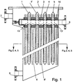
Fig. 1 ein Filtergehäuse mit Einbauten im seitlichen Querschnitt. -
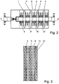
Fig. 2 ein Filtergehäuse mit Einbauten im Querschnitt von oben. -
Fig. 3 Ein detailierter Querschnitt der Filterelemente von oben. -
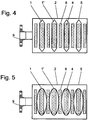
Fig. 4 Ein Querschnitt durch das Filtergehäuse gemässFig. 1 während der Filtration. -
Fig. 5 Ein Querschnitt durch das Filtergehäuse gemässFig. 1 während der Rückspülung. - In
Fig. 1 werden Filterelemente mit den Bezugszeichen 1,1' bezeichnet. Die Filterelemente 1,1' sind in einem Druckbehälter 2 hängend an einem horizontalen Filtratablaufrohr 3 mit Filtratablauflöchern 13,13' befestigt. Innerhalb der Filterelemente 1,1' sind flache Stützgitter 4 vorgesehen, die von einem vollständig geschlossenen Filtermedium 5 umgeben sind. Der Druckbehälter 2 ist mit einem Stutzen 7, einem Stutzen 8 sowie einem Stutzen 9 vorgesehen. Zwischen den einzelnen Filterelementen 1,1' sind Distanzhalter 6,6' vorgesehen. Die Distanzhalter 6,6' ragen weder im unteren noch im oberen Teil über die Filterelemente 1,1' hinaus. - In
Figur 2 sind Einbauten im Querschnitt von oben gezeigt, wobei gleiche Teile mit denselben Bezugszeichne wie inFigur 1 beschrieben sind. - In
Figur 3 sind Stützgitter 4, Filtermedium 5, Distanzhalter 6, die Filtratablaufkanäle 11 und die Suspensionskanäle 12 der Filterelemente 1,1' gezeigt. - In
Fig. 4 ist ein Querschnitt durch das Filtergehäuse gemässFig. 1 während der Filtration dargestellt. - InFig. 5 ein Querschnitt durch das Filtergehäuse gemäss
Fig. 1 während der Rückspülung. - Im Betrieb erfolgt die Zufuhr einer Trübe über den Stutzen 7 in den Druckbehälter 2. Vom Druckbehälter 2 durchströmt die Trübe das Filtermedium 5 und verlässt als Klarfiltrat über die Filtratablaufkanäle 11 des flachen Stützgitters 4 und das horizontale Filtratablaufrohr 3 den Druckbehälter 2. Dabei wird der in der Suspension enthaltene Feststoff vom Filtermedium 5 zurückgehalten und lagert sich auf der Oberfläche des Filtermediums 5 ab. Nach beendeter Filtration erfolgt die Reinigung der Filterelemente durch Rückspülen oder Rückblasen. Dabei verhindern die Distanzhalter 6 dass die Oberflächen der Filtermedien sich durch das aufblähen gegeneinander pressen und sich der Feststoff dazwischen verklemmt. Der abgelöste Feststoff wird dabei durch die Suspensionskanäle 12 aus dem Zwischenraum der Filterelemente herausgespült so dass ein Konzentrat des Feststoffes über den Stutzen 9 am unteren Ende des Druckbehälters 2, ausgetragen werden kann.
- Die Funktionsfähigkeit der Erfindung wurde anhand eines Prototyps geprüft. Dafür wurden fünf Filterelemente mit einer Dicke von < 12 mm einer Breite von 155 mm und einer Länge von 2000 mm in einen Druckbehälter eingebaut. Die aktive Filterfläche betrug 3 m2 und das Behältervolumen weniger als 80 Liter resp. 27 Liter pro m2. Das ist gegenüber bekannten rückspülbaren Druckfiltern, ein signifikanter Unterschied.
Claims (6)
- Vorrichtung zur Abtrennung von Feststoffenpartikeln aus Flüssigkeiten, bestehend aus einem Druckbehälter (2), einem oder mehreren Filterelementregistern mit hängend an einem horizontalen Filtratablaufrohr (3) angeordneten Filterelementen (1,1'), wobei die Filterelemente (1,1') aus einem im wesentlichen flachen Stützgitter (4), einem rundum geschlossenen Filtermedium (5) und dazwischen hängende Distanzhalter (6) bestehen, dadurch gekennzeichnet, dass die Stützgitter (4) aus flachgewalzten Gitterrohren bestehen, die an der Außenseite glatt sind, wobei die Stützgitter (4) im Innern über Längsstege verfügen, welche so ausgebildet sind, dass sich Kanäle bilden, welche den Filtratfluss zum Filtratablaufrohr (3) zulassen.
- Vorrichtung nach Anspruch 1, dadurch gekennzeichnet, dass das Stützgitter (4) aus einem Kunststoff besteht.
- Vorrichtung nach Anspruch 1, dadurch gekennzeichnet, dass die Distanzhalter (6) über Längsstege verfügen.
- Vorrichtung nach Anspruch 3, dadurch gekennzeichnet, dass die Distanzhalter (6) aus einem Kunststoff bestehen.
- Vorrichtung nach Anspruch 1, dadurch gekennzeichnet, dass die Abdichtung der Abstandshalter (10) zwischen den Filterelementen (1,1') aus einem Elastomer bestehen.
- Anwendung der Vorrichtung nach den Ansprüchen 1 - 5 zur Filtration von Feststoffen in einer Flüssigkeit mit einer Partikelgrösse von 0.1 bis 10 Mikrometern und einem Feststoffgehalt von 1 mg/l bis 5000 mg/l.
Applications Claiming Priority (2)
| Application Number | Priority Date | Filing Date | Title |
|---|---|---|---|
| CH01262/11A CH705313A1 (de) | 2011-07-28 | 2011-07-28 | Vorrichtung zur Abtrennung von Feststoffpartikeln aus Flüssigkeiten und deren Anwendung. |
| PCT/CH2012/000061 WO2013013327A1 (de) | 2011-07-28 | 2012-03-15 | Vorrichtung zur abtrennung von feststoffpartikeln aus flüssigkeiten und deren anwendung |
Publications (2)
| Publication Number | Publication Date |
|---|---|
| EP2736619A1 EP2736619A1 (de) | 2014-06-04 |
| EP2736619B1 true EP2736619B1 (de) | 2016-05-18 |
Family
ID=45928590
Family Applications (1)
| Application Number | Title | Priority Date | Filing Date |
|---|---|---|---|
| EP12711744.8A Not-in-force EP2736619B1 (de) | 2011-07-28 | 2012-03-15 | Vorrichtung zur abtrennung von feststoffpartikeln aus flüssigkeiten und deren anwendung |
Country Status (11)
| Country | Link |
|---|---|
| US (1) | US20140131291A1 (de) |
| EP (1) | EP2736619B1 (de) |
| KR (1) | KR20140051911A (de) |
| CN (1) | CN103608078B (de) |
| AU (1) | AU2012286565B2 (de) |
| BR (1) | BR112014001203A2 (de) |
| CA (1) | CA2835652A1 (de) |
| CH (1) | CH705313A1 (de) |
| CL (1) | CL2014000213A1 (de) |
| ES (1) | ES2581004T3 (de) |
| WO (1) | WO2013013327A1 (de) |
Cited By (2)
| Publication number | Priority date | Publication date | Assignee | Title |
|---|---|---|---|---|
| WO2022101731A1 (de) | 2020-11-16 | 2022-05-19 | Drm, Dr. Müller Ag | Filterelement zur abtrennung von feststoffen aus flüssigkeiten und gasen |
| US11446594B2 (en) | 2017-01-30 | 2022-09-20 | Drm, Dr. Müller Ag | Device for separating solid particles from liquids and gases |
Families Citing this family (4)
| Publication number | Priority date | Publication date | Assignee | Title |
|---|---|---|---|---|
| CN104667598B (zh) * | 2015-03-01 | 2017-01-04 | 济南蓝海洋环保水处理技术有限公司 | 一种外压布袋式过滤固液分离系统 |
| CN107576555A (zh) * | 2017-06-02 | 2018-01-12 | 温州汇芯生物科技有限公司 | 分离收集液体样本中目标微粒的装置及方法 |
| CH715193A1 (de) * | 2018-07-23 | 2020-01-31 | Mueller Drm Ag | Vorrichtung zur Abtrennung von Feststoffen aus Flüssigkeiten und Gasen. |
| CN117582712A (zh) * | 2023-12-15 | 2024-02-23 | 安徽菲利特过滤系统股份有限公司 | 一种适用于悬挂结构叠片过滤系统 |
Family Cites Families (14)
| Publication number | Priority date | Publication date | Assignee | Title |
|---|---|---|---|---|
| US1721250A (en) * | 1923-11-27 | 1929-07-16 | Ernest J Sweetland | Filter |
| US2568085A (en) * | 1947-10-10 | 1951-09-18 | John J Naugle | Filtering device |
| FR1422314A (fr) * | 1964-11-12 | 1965-12-24 | élément à toile filtrante | |
| US3642141A (en) | 1970-07-21 | 1972-02-15 | Per Corp. | Filter tube and connection thereof to tube sheet |
| NL176146C (nl) | 1977-04-28 | 1985-03-01 | Mueller Drm Ag | Cilindervormig filterorgaan. |
| JPS5952507A (ja) * | 1982-06-03 | 1984-03-27 | デ−・エル・エム・ドクトル・ミユラ−・アクチエンゲゼルシヤフト | 懸濁液を連続的に濃縮する装置 |
| CH678399A5 (de) | 1989-06-09 | 1991-09-13 | Mueller Drm Ag | |
| US5035799A (en) * | 1989-08-21 | 1991-07-30 | Clear Flow, Inc. | Filter assembly |
| DE4237714C2 (de) * | 1992-11-09 | 1996-02-29 | Isp Investments Inc | Crossflow-Anschwemmfiltrationsverfahren |
| JPH08131783A (ja) * | 1994-11-10 | 1996-05-28 | Nitto Denko Corp | 膜分離装置 |
| EP1461140A1 (de) * | 2002-01-02 | 2004-09-29 | Triple I | Modul mit selbsttragenden membranfolien |
| CN2538403Y (zh) * | 2002-04-02 | 2003-03-05 | 宋志骥 | 搅拌洗涤立式过滤机 |
| CN200951345Y (zh) * | 2006-08-23 | 2007-09-26 | 云南省环境科学研究院 | 一种固液分离装置 |
| SG182176A1 (en) * | 2007-07-03 | 2012-07-30 | Sumitomo Elec Fine Polymer Inc | Flat sheet membrane element for filtration and flat sheet membrane filtration module |
-
2011
- 2011-07-28 CH CH01262/11A patent/CH705313A1/de not_active Application Discontinuation
-
2012
- 2012-03-15 WO PCT/CH2012/000061 patent/WO2013013327A1/de not_active Ceased
- 2012-03-15 CN CN201280027710.2A patent/CN103608078B/zh not_active Expired - Fee Related
- 2012-03-15 BR BR112014001203A patent/BR112014001203A2/pt not_active IP Right Cessation
- 2012-03-15 CA CA2835652A patent/CA2835652A1/en not_active Abandoned
- 2012-03-15 ES ES12711744.8T patent/ES2581004T3/es active Active
- 2012-03-15 KR KR1020147001938A patent/KR20140051911A/ko not_active Ceased
- 2012-03-15 AU AU2012286565A patent/AU2012286565B2/en not_active Ceased
- 2012-03-15 EP EP12711744.8A patent/EP2736619B1/de not_active Not-in-force
- 2012-03-15 US US14/124,942 patent/US20140131291A1/en not_active Abandoned
-
2014
- 2014-01-28 CL CL2014000213A patent/CL2014000213A1/es unknown
Cited By (3)
| Publication number | Priority date | Publication date | Assignee | Title |
|---|---|---|---|---|
| US11446594B2 (en) | 2017-01-30 | 2022-09-20 | Drm, Dr. Müller Ag | Device for separating solid particles from liquids and gases |
| WO2022101731A1 (de) | 2020-11-16 | 2022-05-19 | Drm, Dr. Müller Ag | Filterelement zur abtrennung von feststoffen aus flüssigkeiten und gasen |
| US12502633B2 (en) | 2020-11-16 | 2025-12-23 | Drm, Dr. Muller Ag | Filter element for separating solids from liquids and gases |
Also Published As
| Publication number | Publication date |
|---|---|
| KR20140051911A (ko) | 2014-05-02 |
| CL2014000213A1 (es) | 2014-11-21 |
| WO2013013327A1 (de) | 2013-01-31 |
| BR112014001203A2 (pt) | 2017-02-21 |
| EP2736619A1 (de) | 2014-06-04 |
| US20140131291A1 (en) | 2014-05-15 |
| CH705313A1 (de) | 2013-01-31 |
| CN103608078B (zh) | 2015-12-02 |
| AU2012286565B2 (en) | 2015-04-30 |
| CA2835652A1 (en) | 2013-01-31 |
| AU2012286565A1 (en) | 2014-01-30 |
| CN103608078A (zh) | 2014-02-26 |
| ES2581004T3 (es) | 2016-08-30 |
Similar Documents
| Publication | Publication Date | Title |
|---|---|---|
| DE2457289C3 (de) | Trennanordnung für ein öl-Wasser-Gemisch | |
| DE4319261C2 (de) | Schraubenförmig umwickeltes Filterelement | |
| DE10106722B4 (de) | Spezielles Hohlfaser-Membranmodul für den Einsatz in stark durch fouling beeinträchtigten Prozessen und seine Herstellung | |
| EP0969910B1 (de) | Filtrationsvorrichtung | |
| EP2736619A1 (de) | Vorrichtung zur abtrennung von feststoffpartikeln aus flüssigkeiten und deren anwendung | |
| EP1812147B1 (de) | Vorrichtung zum filtern von stoffen aus flüssigkeiten | |
| DE3317517A1 (de) | Vorrichtung zum filtern und trennen von fluessigen und gasfoermigen medien | |
| DE3914592A1 (de) | Verfahren, vorrichtung und filtermodul zur filtration von fluessigkeiten im cross-flow-betrieb | |
| EP0891221A1 (de) | Membranmodul einer anlage zur membrantrennung, dessen anwendung und verfahren zu dessen herstellung | |
| EP0291883A2 (de) | Filtermodul aus Schichtenfilterelementen | |
| DE2123683C3 (de) | Filtereinrichtung | |
| DE3816434A1 (de) | Filtermodul aus schichtenfilterelementen | |
| DE2439311C3 (de) | ||
| CH700892B1 (de) | Filtermodul und Filtervorrichtung. | |
| DE69715005T2 (de) | Multimembranfilter | |
| DE602005003548T2 (de) | Abtrennung von festen partikeln aus den sie enthaltenden dispersionen | |
| AT392300B (de) | Eindicker | |
| EP0480874B1 (de) | Filter zur Teilchenabscheidung | |
| EP0645446B1 (de) | Vorrichtung zur Aufnahme von Stabilisierungsmittel für Getränke und andere Flüssigkeiten | |
| EP0788822B1 (de) | Flüssigkeitsfilter | |
| DE102012024349A1 (de) | Filter zur Filtrierung von Flüssigkeiten und Filterelement eines derartigen Filters | |
| DE73740C (de) | Filtrirapparat | |
| AT512535B1 (de) | Filtereinrichtung | |
| DE4128747A1 (de) | Filter zur teilchenabscheidung | |
| DE2433969A1 (de) | Schwebstoffilter |
Legal Events
| Date | Code | Title | Description |
|---|---|---|---|
| PUAI | Public reference made under article 153(3) epc to a published international application that has entered the european phase |
Free format text: ORIGINAL CODE: 0009012 |
|
| 17P | Request for examination filed |
Effective date: 20130709 |
|
| AK | Designated contracting states |
Kind code of ref document: A1 Designated state(s): AL AT BE BG CH CY CZ DE DK EE ES FI FR GB GR HR HU IE IS IT LI LT LU LV MC MK MT NL NO PL PT RO RS SE SI SK SM TR |
|
| DAX | Request for extension of the european patent (deleted) | ||
| GRAP | Despatch of communication of intention to grant a patent |
Free format text: ORIGINAL CODE: EPIDOSNIGR1 |
|
| INTG | Intention to grant announced |
Effective date: 20160210 |
|
| GRAS | Grant fee paid |
Free format text: ORIGINAL CODE: EPIDOSNIGR3 |
|
| GRAA | (expected) grant |
Free format text: ORIGINAL CODE: 0009210 |
|
| AK | Designated contracting states |
Kind code of ref document: B1 Designated state(s): AL AT BE BG CH CY CZ DE DK EE ES FI FR GB GR HR HU IE IS IT LI LT LU LV MC MK MT NL NO PL PT RO RS SE SI SK SM TR |
|
| REG | Reference to a national code |
Ref country code: GB Ref legal event code: FG4D Free format text: NOT ENGLISH |
|
| REG | Reference to a national code |
Ref country code: CH Ref legal event code: EP |
|
| REG | Reference to a national code |
Ref country code: IE Ref legal event code: FG4D Free format text: LANGUAGE OF EP DOCUMENT: GERMAN Ref country code: AT Ref legal event code: REF Ref document number: 799924 Country of ref document: AT Kind code of ref document: T Effective date: 20160615 |
|
| REG | Reference to a national code |
Ref country code: DE Ref legal event code: R096 Ref document number: 502012007146 Country of ref document: DE |
|
| REG | Reference to a national code |
Ref country code: NL Ref legal event code: FP |
|
| REG | Reference to a national code |
Ref country code: ES Ref legal event code: FG2A Ref document number: 2581004 Country of ref document: ES Kind code of ref document: T3 Effective date: 20160830 |
|
| REG | Reference to a national code |
Ref country code: LT Ref legal event code: MG4D |
|
| PG25 | Lapsed in a contracting state [announced via postgrant information from national office to epo] |
Ref country code: LT Free format text: LAPSE BECAUSE OF FAILURE TO SUBMIT A TRANSLATION OF THE DESCRIPTION OR TO PAY THE FEE WITHIN THE PRESCRIBED TIME-LIMIT Effective date: 20160518 Ref country code: NO Free format text: LAPSE BECAUSE OF FAILURE TO SUBMIT A TRANSLATION OF THE DESCRIPTION OR TO PAY THE FEE WITHIN THE PRESCRIBED TIME-LIMIT Effective date: 20160818 Ref country code: FI Free format text: LAPSE BECAUSE OF FAILURE TO SUBMIT A TRANSLATION OF THE DESCRIPTION OR TO PAY THE FEE WITHIN THE PRESCRIBED TIME-LIMIT Effective date: 20160518 |
|
| PG25 | Lapsed in a contracting state [announced via postgrant information from national office to epo] |
Ref country code: HR Free format text: LAPSE BECAUSE OF FAILURE TO SUBMIT A TRANSLATION OF THE DESCRIPTION OR TO PAY THE FEE WITHIN THE PRESCRIBED TIME-LIMIT Effective date: 20160518 Ref country code: PT Free format text: LAPSE BECAUSE OF FAILURE TO SUBMIT A TRANSLATION OF THE DESCRIPTION OR TO PAY THE FEE WITHIN THE PRESCRIBED TIME-LIMIT Effective date: 20160919 Ref country code: SE Free format text: LAPSE BECAUSE OF FAILURE TO SUBMIT A TRANSLATION OF THE DESCRIPTION OR TO PAY THE FEE WITHIN THE PRESCRIBED TIME-LIMIT Effective date: 20160518 Ref country code: LV Free format text: LAPSE BECAUSE OF FAILURE TO SUBMIT A TRANSLATION OF THE DESCRIPTION OR TO PAY THE FEE WITHIN THE PRESCRIBED TIME-LIMIT Effective date: 20160518 Ref country code: GR Free format text: LAPSE BECAUSE OF FAILURE TO SUBMIT A TRANSLATION OF THE DESCRIPTION OR TO PAY THE FEE WITHIN THE PRESCRIBED TIME-LIMIT Effective date: 20160819 Ref country code: RS Free format text: LAPSE BECAUSE OF FAILURE TO SUBMIT A TRANSLATION OF THE DESCRIPTION OR TO PAY THE FEE WITHIN THE PRESCRIBED TIME-LIMIT Effective date: 20160518 |
|
| PG25 | Lapsed in a contracting state [announced via postgrant information from national office to epo] |
Ref country code: CZ Free format text: LAPSE BECAUSE OF FAILURE TO SUBMIT A TRANSLATION OF THE DESCRIPTION OR TO PAY THE FEE WITHIN THE PRESCRIBED TIME-LIMIT Effective date: 20160518 Ref country code: RO Free format text: LAPSE BECAUSE OF FAILURE TO SUBMIT A TRANSLATION OF THE DESCRIPTION OR TO PAY THE FEE WITHIN THE PRESCRIBED TIME-LIMIT Effective date: 20160518 Ref country code: DK Free format text: LAPSE BECAUSE OF FAILURE TO SUBMIT A TRANSLATION OF THE DESCRIPTION OR TO PAY THE FEE WITHIN THE PRESCRIBED TIME-LIMIT Effective date: 20160518 Ref country code: SK Free format text: LAPSE BECAUSE OF FAILURE TO SUBMIT A TRANSLATION OF THE DESCRIPTION OR TO PAY THE FEE WITHIN THE PRESCRIBED TIME-LIMIT Effective date: 20160518 Ref country code: EE Free format text: LAPSE BECAUSE OF FAILURE TO SUBMIT A TRANSLATION OF THE DESCRIPTION OR TO PAY THE FEE WITHIN THE PRESCRIBED TIME-LIMIT Effective date: 20160518 |
|
| REG | Reference to a national code |
Ref country code: DE Ref legal event code: R097 Ref document number: 502012007146 Country of ref document: DE |
|
| PG25 | Lapsed in a contracting state [announced via postgrant information from national office to epo] |
Ref country code: SM Free format text: LAPSE BECAUSE OF FAILURE TO SUBMIT A TRANSLATION OF THE DESCRIPTION OR TO PAY THE FEE WITHIN THE PRESCRIBED TIME-LIMIT Effective date: 20160518 Ref country code: PL Free format text: LAPSE BECAUSE OF FAILURE TO SUBMIT A TRANSLATION OF THE DESCRIPTION OR TO PAY THE FEE WITHIN THE PRESCRIBED TIME-LIMIT Effective date: 20160518 |
|
| REG | Reference to a national code |
Ref country code: FR Ref legal event code: PLFP Year of fee payment: 6 |
|
| PLBE | No opposition filed within time limit |
Free format text: ORIGINAL CODE: 0009261 |
|
| STAA | Information on the status of an ep patent application or granted ep patent |
Free format text: STATUS: NO OPPOSITION FILED WITHIN TIME LIMIT |
|
| 26N | No opposition filed |
Effective date: 20170221 |
|
| PGFP | Annual fee paid to national office [announced via postgrant information from national office to epo] |
Ref country code: FR Payment date: 20170322 Year of fee payment: 6 Ref country code: CH Payment date: 20170205 Year of fee payment: 6 |
|
| PG25 | Lapsed in a contracting state [announced via postgrant information from national office to epo] |
Ref country code: SI Free format text: LAPSE BECAUSE OF FAILURE TO SUBMIT A TRANSLATION OF THE DESCRIPTION OR TO PAY THE FEE WITHIN THE PRESCRIBED TIME-LIMIT Effective date: 20160518 |
|
| PGFP | Annual fee paid to national office [announced via postgrant information from national office to epo] |
Ref country code: AT Payment date: 20170322 Year of fee payment: 6 Ref country code: BE Payment date: 20170321 Year of fee payment: 6 |
|
| PG25 | Lapsed in a contracting state [announced via postgrant information from national office to epo] |
Ref country code: MC Free format text: LAPSE BECAUSE OF FAILURE TO SUBMIT A TRANSLATION OF THE DESCRIPTION OR TO PAY THE FEE WITHIN THE PRESCRIBED TIME-LIMIT Effective date: 20160518 |
|
| REG | Reference to a national code |
Ref country code: IE Ref legal event code: MM4A |
|
| PG25 | Lapsed in a contracting state [announced via postgrant information from national office to epo] |
Ref country code: LU Free format text: LAPSE BECAUSE OF NON-PAYMENT OF DUE FEES Effective date: 20170315 |
|
| PG25 | Lapsed in a contracting state [announced via postgrant information from national office to epo] |
Ref country code: IE Free format text: LAPSE BECAUSE OF NON-PAYMENT OF DUE FEES Effective date: 20170315 |
|
| PGFP | Annual fee paid to national office [announced via postgrant information from national office to epo] |
Ref country code: GB Payment date: 20180321 Year of fee payment: 7 Ref country code: NL Payment date: 20180321 Year of fee payment: 7 |
|
| PGFP | Annual fee paid to national office [announced via postgrant information from national office to epo] |
Ref country code: ES Payment date: 20180430 Year of fee payment: 7 |
|
| PGFP | Annual fee paid to national office [announced via postgrant information from national office to epo] |
Ref country code: IT Payment date: 20180326 Year of fee payment: 7 |
|
| PG25 | Lapsed in a contracting state [announced via postgrant information from national office to epo] |
Ref country code: MT Free format text: LAPSE BECAUSE OF FAILURE TO SUBMIT A TRANSLATION OF THE DESCRIPTION OR TO PAY THE FEE WITHIN THE PRESCRIBED TIME-LIMIT Effective date: 20160518 |
|
| PG25 | Lapsed in a contracting state [announced via postgrant information from national office to epo] |
Ref country code: AL Free format text: LAPSE BECAUSE OF FAILURE TO SUBMIT A TRANSLATION OF THE DESCRIPTION OR TO PAY THE FEE WITHIN THE PRESCRIBED TIME-LIMIT Effective date: 20160518 |
|
| REG | Reference to a national code |
Ref country code: CH Ref legal event code: PL |
|
| REG | Reference to a national code |
Ref country code: AT Ref legal event code: MM01 Ref document number: 799924 Country of ref document: AT Kind code of ref document: T Effective date: 20180315 |
|
| REG | Reference to a national code |
Ref country code: BE Ref legal event code: MM Effective date: 20180331 |
|
| PG25 | Lapsed in a contracting state [announced via postgrant information from national office to epo] |
Ref country code: AT Free format text: LAPSE BECAUSE OF NON-PAYMENT OF DUE FEES Effective date: 20180315 |
|
| PG25 | Lapsed in a contracting state [announced via postgrant information from national office to epo] |
Ref country code: LI Free format text: LAPSE BECAUSE OF NON-PAYMENT OF DUE FEES Effective date: 20180331 Ref country code: CH Free format text: LAPSE BECAUSE OF NON-PAYMENT OF DUE FEES Effective date: 20180331 Ref country code: BE Free format text: LAPSE BECAUSE OF NON-PAYMENT OF DUE FEES Effective date: 20180331 |
|
| PG25 | Lapsed in a contracting state [announced via postgrant information from national office to epo] |
Ref country code: FR Free format text: LAPSE BECAUSE OF NON-PAYMENT OF DUE FEES Effective date: 20180331 |
|
| PG25 | Lapsed in a contracting state [announced via postgrant information from national office to epo] |
Ref country code: HU Free format text: LAPSE BECAUSE OF FAILURE TO SUBMIT A TRANSLATION OF THE DESCRIPTION OR TO PAY THE FEE WITHIN THE PRESCRIBED TIME-LIMIT; INVALID AB INITIO Effective date: 20120315 |
|
| PG25 | Lapsed in a contracting state [announced via postgrant information from national office to epo] |
Ref country code: BG Free format text: LAPSE BECAUSE OF FAILURE TO SUBMIT A TRANSLATION OF THE DESCRIPTION OR TO PAY THE FEE WITHIN THE PRESCRIBED TIME-LIMIT Effective date: 20160518 |
|
| PG25 | Lapsed in a contracting state [announced via postgrant information from national office to epo] |
Ref country code: CY Free format text: LAPSE BECAUSE OF NON-PAYMENT OF DUE FEES Effective date: 20160518 |
|
| REG | Reference to a national code |
Ref country code: NL Ref legal event code: MM Effective date: 20190401 |
|
| GBPC | Gb: european patent ceased through non-payment of renewal fee |
Effective date: 20190315 |
|
| PG25 | Lapsed in a contracting state [announced via postgrant information from national office to epo] |
Ref country code: MK Free format text: LAPSE BECAUSE OF FAILURE TO SUBMIT A TRANSLATION OF THE DESCRIPTION OR TO PAY THE FEE WITHIN THE PRESCRIBED TIME-LIMIT Effective date: 20160518 |
|
| PG25 | Lapsed in a contracting state [announced via postgrant information from national office to epo] |
Ref country code: GB Free format text: LAPSE BECAUSE OF NON-PAYMENT OF DUE FEES Effective date: 20190315 Ref country code: NL Free format text: LAPSE BECAUSE OF NON-PAYMENT OF DUE FEES Effective date: 20190401 |
|
| PG25 | Lapsed in a contracting state [announced via postgrant information from national office to epo] |
Ref country code: IT Free format text: LAPSE BECAUSE OF NON-PAYMENT OF DUE FEES Effective date: 20190315 |
|
| PG25 | Lapsed in a contracting state [announced via postgrant information from national office to epo] |
Ref country code: TR Free format text: LAPSE BECAUSE OF FAILURE TO SUBMIT A TRANSLATION OF THE DESCRIPTION OR TO PAY THE FEE WITHIN THE PRESCRIBED TIME-LIMIT Effective date: 20160518 |
|
| PGFP | Annual fee paid to national office [announced via postgrant information from national office to epo] |
Ref country code: DE Payment date: 20200320 Year of fee payment: 9 |
|
| REG | Reference to a national code |
Ref country code: ES Ref legal event code: FD2A Effective date: 20200727 |
|
| PG25 | Lapsed in a contracting state [announced via postgrant information from national office to epo] |
Ref country code: IS Free format text: LAPSE BECAUSE OF FAILURE TO SUBMIT A TRANSLATION OF THE DESCRIPTION OR TO PAY THE FEE WITHIN THE PRESCRIBED TIME-LIMIT Effective date: 20160918 |
|
| PG25 | Lapsed in a contracting state [announced via postgrant information from national office to epo] |
Ref country code: ES Free format text: LAPSE BECAUSE OF NON-PAYMENT OF DUE FEES Effective date: 20190316 |
|
| REG | Reference to a national code |
Ref country code: DE Ref legal event code: R119 Ref document number: 502012007146 Country of ref document: DE |
|
| PG25 | Lapsed in a contracting state [announced via postgrant information from national office to epo] |
Ref country code: DE Free format text: LAPSE BECAUSE OF NON-PAYMENT OF DUE FEES Effective date: 20211001 |