EP2736639B1 - Dichtes verbindungsstück zum aseptiscen transfer von biopharmazeutischen produkten - Google Patents
Dichtes verbindungsstück zum aseptiscen transfer von biopharmazeutischen produkten Download PDFInfo
- Publication number
- EP2736639B1 EP2736639B1 EP12744091.5A EP12744091A EP2736639B1 EP 2736639 B1 EP2736639 B1 EP 2736639B1 EP 12744091 A EP12744091 A EP 12744091A EP 2736639 B1 EP2736639 B1 EP 2736639B1
- Authority
- EP
- European Patent Office
- Prior art keywords
- container
- stationary
- functional
- annular
- locking
- Prior art date
- Legal status (The legal status is an assumption and is not a legal conclusion. Google has not performed a legal analysis and makes no representation as to the accuracy of the status listed.)
- Active
Links
Images




Classifications
-
- B—PERFORMING OPERATIONS; TRANSPORTING
- B01—PHYSICAL OR CHEMICAL PROCESSES OR APPARATUS IN GENERAL
- B01L—CHEMICAL OR PHYSICAL LABORATORY APPARATUS FOR GENERAL USE
- B01L1/00—Enclosures; Chambers
- B01L1/02—Air-pressure chambers; Air-locks therefor
-
- C—CHEMISTRY; METALLURGY
- C12—BIOCHEMISTRY; BEER; SPIRITS; WINE; VINEGAR; MICROBIOLOGY; ENZYMOLOGY; MUTATION OR GENETIC ENGINEERING
- C12M—APPARATUS FOR ENZYMOLOGY OR MICROBIOLOGY; APPARATUS FOR CULTURING MICROORGANISMS FOR PRODUCING BIOMASS, FOR GROWING CELLS OR FOR OBTAINING FERMENTATION OR METABOLIC PRODUCTS, i.e. BIOREACTORS OR FERMENTERS
- C12M37/00—Means for sterilizing, maintaining sterile conditions or avoiding chemical or biological contamination
- C12M37/04—Seals
-
- G—PHYSICS
- G21—NUCLEAR PHYSICS; NUCLEAR ENGINEERING
- G21F—PROTECTION AGAINST X-RADIATION, GAMMA RADIATION, CORPUSCULAR RADIATION OR PARTICLE BOMBARDMENT; TREATING RADIOACTIVELY CONTAMINATED MATERIAL; DECONTAMINATION ARRANGEMENTS THEREFOR
- G21F7/00—Shielded cells or rooms
- G21F7/005—Shielded passages through walls; Locks; Transferring devices between rooms
Definitions
- the invention relates to the field of aseptic transfer of biopharmaceutical products between a container and a closed container.
- the invention relates, in a first aspect, to a sealing junction device specifically intended to ensure the aseptic transfer of products belonging to the biopharmaceutical field between a container and a closed enclosure.
- the invention also relates, in a second aspect, an assembly comprising a container, such a sealed connection device and an enclosure for ensuring the aseptic transfer of biopharmaceutical products between the container and the closed enclosure.
- the invention further relates, in a third aspect, to a process for aseptic transfer of a biopharmaceutical product between the container and the closed container.
- biopharmaceutical product or biopharmaceutical product which is related to biotechnology, pharmacy and more generally to the medical field.
- a biopharmaceutical product is a product derived from biotechnology - culture media, cell cultures, buffer solutions, artificial nutrition liquids - or a product intended for use in the pharmaceutical or medical field, at least in part, in the form of solid more or less finely divided, in liquid form, or in pasty form or, more generally, a material product - stopper, container, tube or integrated ports, syringe, syringe plunger, functional means of treatment or conditioning, together more or less complex comprising a plurality of products, etc. - intended to be used inside the closed enclosure.
- the terms “container” or “container” refer to what, in biopharmacy, is fit and intended in its internal space, to contain, enclose or contain a certain biopharmaceutical content or, where appropriate, more than one biopharmaceutical content, more statically or less durable or durable.
- biopharmaceutical content typically consists of one or more biopharmaceutical product (s) as defined previously.
- Such containers may be rigid or flexible, disposable or reusable, of various sizes and are for example pockets, sheaths, containers, containers, bioreactors or troughs for biopharmaceutical use, this list being not limiting.
- This junction device comprises stationary means of temporary clamping formed by a first annular ring rotatable about a geometric axis and allowing, via the movement of a push button causing the rotation of this first annular ring, to actuate axial clamping elements to maintain the container against the door of the enclosure.
- the junction device also comprises stationary unlocking and locking means, arranged on the wall of the enclosure and for moving the container from an initial locking position in which a removable cover hermetically seals the container to a position of intermediate unlocking in which the removable cover is detached from the container and held tightly against the enclosure door to ensure the aseptic transfer of biopharmaceutical products.
- These stationary unlocking and locking means consist of a second toothed annular ring, rotatable about a geometric axis of rotation coinciding with the geometric axis of the first annular ring and movable by the manipulation of a lever. .
- the movement of the lever in one direction makes it possible to drive the toothed annular ring in this direction and thus to unlock the removable lid of the container, while the movement of the lever in the other direction makes it possible to drive the annular ring gear to rotate in the opposite direction and thus to lock the removable lid against the container again.
- this solution involves manipulating three independent levers, arranged around the perimeter of the door of the enclosure to ensure the locking and unlocking of the removable lid of the container.
- the risks of handling errors are multiplied, as are the risk areas likely to cause losses of integrity inside the enclosure or container.
- WO-A1-2010 / 054031 which relates to a sealed junction device having stationary locking / unlocking means similar to those described with reference to the preceding documents.
- this waterproof junction device can be used with containers with onboard locking / unlocking means positioned directly on the periphery of the annular flange.
- These onboard locking / unlocking means are formed by a plurality of manipulable pins, independently of one another and reversibly movable from a position in which they are introduced only into the flange of the container - the removable cover being then free - to a position in which they are introduced simultaneously into the flange of the container and into the removable lid - the latter then being held in position so as to seal the container.
- Such an embodiment also has several disadvantages. Firstly, the presence of several pins for locking the removable cover on the container and movable independently of each other does not ensure optimum reliability as to the loss of integrity of the connecting device. Indeed, the probabilities are important that the manipulation of these different pins, according to specific movements for the locking and unlocking of the removable cover, generate human errors that may cause a lack of insulation inside one or the other of the container and the enclosure. Secondly, the use of such manually movable pins causes accelerated wear of the material which must be replaced more regularly. Thirdly, it should be emphasized that, as before, the automation of such a system would be particularly complex and therefore expensive.
- the document WO2010 / 054031 discloses a container for ensuring the aseptic transfer of a product to an enclosure.
- the container comprises an annular flange defining an opening and there is provided a removable cover.
- the document FR 2,872,446 discloses a double-door sealed transfer device for ensuring a tight transfer between a first sealed enclosure, for example a containment cell and a second sealed enclosure, for example a transfer case, comprising two doors each equipped with locking means for the locking on a flange having a central opening and an actuating member for actuating the locking means, wherein the actuating members are rotatably mounted in the doors and comprise a porthole.
- the document GB 2 218 663 discloses a double lid system comprising a first cylindrical container, open at one end, a first lid for the first container, means defining an orifice for a second container, and a second lid for said orifice, the first container having a seal sealing device means for the port and the first cover, and the second cover having a peripheral seal at the orifice of the means and the first cover, wherein the first cover comprises a capture mechanism of a first rotary member for fixing the first lid to the first container, the first container comprising means with which the capture mechanism of the first rotatable member can engage, the second lid incorporates a rotatable shaft extending therethrough, and is provided means for rotating the shaft, and a capture mechanism of the second rotary member which can be actuated by the shaft for attaching the first lid to the second lid, the first lid having means with which the capture mechanism of the second rotatable member can engage, the system finally incorporating a jaw mechanism with at least twenty teeth engaging when the first cover is adjacent to the second cover
- the document GB 2,102,719 discloses a system for passing hazardous materials into and out of an enclosure, such as a glove box, through an orifice in a wall of the enclosure.
- the orifice is normally closed by a door, which cooperates with a removable end closure on a container or the like when it is presented to and attached to the orifice.
- the container is fixed in position to the orifice by means of a rotatable coupling ring.
- a locking device ensures that the door can not be opened in the absence of a container in the port and that the container can not be opened. be removed from the port when the door is open.
- a glove secured to a rigid sleeve may be used to allow the operator to perform a work function within the glove box.
- the purpose of the invention is therefore to propose a sealed junction device free from at least one of the limitations mentioned above.
- the invention relates to such a sealing junction device for ensuring the transfer of biopharmaceutical products by limiting the number of handling to be performed and the risks of leaks, which may be caused by errors in handling.
- the invention relates to a sealing junction device for ensuring the aseptic transfer of a biopharmaceutical product between an enclosure provided with a removable door and a container provided with a removable cover, comprising: stationary clamping means temporary able to maintain the container clamped against the enclosure so that the removable cover of said container is applied tightly against the door of said enclosure; stationary unlocking means adapted to move the container from an initial locking position in which the removable cover hermetically seals the container to an intermediate unlocking position in which the removable cover is separated from the container and hermetically held against the enclosure door so as to provide aseptic communication between said container and said enclosure; stationary locking means adapted to move the container from the intermediate unlocking position to a final locking position in which said removable cover hermetically seals the container; an annular functional ring adapted to move by rotation about a geometric axis of rotation so as to actuate the stationary unlocking means and the stationary locking means of the container.
- the invention is characterized in that the stationary temporary clamping means, the stationary unlocking means and the stationary locking means are mechanically connected to the annular functional ring and arranged so that the unidirectional rotation of said functional ring annular around the geometric axis of rotation successively causes the actuation of stationary temporary clamping means ensuring the holding in position of the container against the enclosure, then the actuation of the stationary unlocking means ensuring the passage to the intermediate unlocking position of the container, then the actuation of the stationary locking means of the container ensuring the passage to the final locking position of the container, and the actuation of stationary temporary clamping means of the container ensuring the release of the container.
- This embodiment has several advantages.
- the sealed junction device further comprises stationary locking / unlocking means able to prevent / authorize the opening of the enclosure door and mechanically linked to the annular functional ring so that the unidirectional rotation of the annular functional ring around the geometric axis of rotation successively causes the actuation of temporary stationary clamping means ensuring the holding in position of the container against the enclosure, and simultaneously or successively the actuation of the stationary unlocking means ensuring the passage of intermediate unlocking position of the container and the actuation of the stationary locking / unlocking means ensuring the unlocking of the removable door of the enclosure, then the actuation of the stationary locking means of the container ensuring the passage to the final locking position of the container , then simultaneously or suc the activation of the stationary locking / unlocking means ensuring the blocking of the removable door of the enclosure and the actuation of the stationary locking means ensuring the passage to the final locking position of the container, then the actuation of stationary temporary clamping means to ensure the release of the container vis-à- screw of the speaker.
- the stationary locking / unlocking means comprise at least one stationary blocking / unlocking functional arrangement formed by a functional ring gear portion and a blocking member capable of being engrained by the crown portion. functional gear so that during the unidirectional rotation of the functional ring the locking member moves from a locked position in which a covering portion prevents the door of the enclosure from opening to an unlocked position in which the overlap portion no longer prevents the enclosure door from opening.
- the use of a lap portion mechanically driven by the annular ring makes it possible to secure the blocking of the door of the enclosure while avoiding that a problem of servocontrol or operation (of sensors, cylinders, automata, etc.) does not create a security breach.
- the stationary unlocking means comprise at least one stationary unlocking functional arrangement formed by a functional crown portion forming a radial cam with an internal and / or external profile and a radial displacement pushing element cooperating with the functional crown portion forming radial cam so that, during the unidirectional rotation of the functional ring to an intermediate unlocking position, the pusher element moves and moves the container from the initial locking position to the intermediate unlocking position.
- a functional crown forming a radial cam with an internal or external profile arranged on the ring makes it possible to simplify the management of the dimensioning, the displacements and the time operation of the stationary initial locking means.
- the use of push elements combined with this radial cam system is also a reliable, accurate and compact solution.
- the stationary locking means comprise at least one stationary interlocking functional arrangement formed by a functional radial crown forming section with an internal and / or external profile, and a radial displacement pushing element cooperating with the functional crown portion. forming a radial cam so that, during the unidirectional rotation of the functional ring to a final locking position, the pusher element moves and moves the removable container cover from the intermediate unlocking position to the locking position final.
- the functional crown forming a radial cam with internal or external profiling makes it possible to simplify the actuation temporal stationary unlocking means and facilitate the management of the sizing and displacements of the stationary final locking means.
- the radial cam functional crown portion of the stationary locking and / or unlocking means is formed by a guide path arranged in the annular functional ring and the radial displacement pushing element of said stationary means.
- locking and / or unlocking comprises a roller arranged in the guide path so that the rotation of the annular functional ring generates a radial displacement of the roller which causes the corresponding displacement of an activation pin.
- the stationary unlocking functional arrangement and the stationary locking functional arrangement are composed of the same radial displacement pusher element.
- the radial cam-forming functional crown portion of the stationary locking functional arrangement is arranged in the extension of the radial cam-forming functional crown portion the stationary unlocking functional arrangement with respect to the one-way direction of rotation. of the annular functional crown.
- the radial cam-shaped crown portions of the stationary locking functional arrangement and the stationary unlocking functional arrangement are formed by a continuous guide path arranged in the annular functional ring and the element.
- the radial displacement plunger comprises a roller arranged in the continuous guide path so that the rotation of the annular functional ring generates a radial displacement of the roller which causes the corresponding displacement of an activation pin.
- the stationary unlocking means and the stationary locking means may however be structurally and functionally distinct and independent of one another.
- the temporary stationary clamping means comprise at least one stationary temporary clamping functional arrangement made from a functional clamping crown portion having, on the one hand, a functional axial clamping surface and, on the other hand, on the one hand, an introduction opening of complementary clamping on-board means arranged on a portion of the outer periphery of the container.
- a portion functional ring forming clamping to maintain the axial position of the container limits the manufacturing costs by avoiding the use of a separate part of the annular functional ring.
- this solution comprising an axial clamping functional surface and an insertion opening makes it possible to index the position of the container at the time of its installation against the sealed junction arrangement.
- this solution is reassuring since, since the functional crown portion clamping is mechanically linked to the stationary unlocking and locking means, it is impossible for the flange of the container to be released prematurely.
- the functional ring forming portion clamping is performed on an inner peripheral periphery of the annular functional ring.
- the sealed junction device also comprises stationary means for operating the door of the enclosure capable of opening and sealing the door of the enclosure.
- the stationary operating means of the enclosure door are mechanically driven by the annular functional ring.
- the mechanical association of the stationary operating means of the door of the enclosure on the annular functional ring makes it possible to guarantee the temporal actuation of the door and to simplify, for the same reasons as previously, the sealed connection device.
- the stationary operating means of the door of the chamber are driven by a control motor servo on the displacement of the annular functional ring.
- the sealed junction device comprises stationary maneuvering means
- the latter it is possible for the latter to be able to move the door firstly in an axial direction and then in a direction substantially perpendicular to the direction. axial so that the door does not impede the passage of the biopharmaceutical product. In this way, the door of the enclosure, once opened, does not obstruct access to the container.
- the annular functional ring, the stationary temporary clamping means of the container, the stationary unlocking means of the container and the stationary locking means of the container are positioned outside the enclosure.
- the placement of these elements outside the enclosure simplifies the implementation and repair operations since they are not in a hermetic environment inside the enclosure but are instead accessible from the outside.
- the functional gear ring portion of the stationary blocking / unlocking functional arrangement is positioned at the outside of the enclosure
- the blocking member of said stationary blocking / unlocking functional arrangement is positioned inside the enclosure and, thirdly, said blocking member is driven by a shaft rotation which passes through a peripheral wall of the enclosure.
- the temporary stationary clamping means of the container, the stationary unlocking means of the container and the stationary locking means of the container comprise, respectively, a stationary functional arrangement (s) of temporary clamping, stationary stationary functional arrangement (s), a stationary locking functional arrangement (s), with n greater than or equal to 1, so that at each rotational movement of the annular functional ring in the unidirectional direction relating to 1 / n complete rotation corresponds to the successive actuation of stationary temporary clamping means of the container ensuring the position of the container against the enclosure, stationary means for unlocking the container ensuring the passage in the intermediate unlocking position of the container, stationary means for locking the container ensuring the passage of final locking position of the container, temporary stationary clamping means of the container ensuring the release of said container.
- n may be 3 or 4.
- the invention relates to an assembly comprising an enclosure and a sealing junction device specially adapted to be associated with a disposable type container provided with a removable cover for the purpose of carrying out the aseptic transfer of a product.
- biopharmaceutical between the enclosure and the container wherein the enclosure comprises a closed peripheral wall in which is arranged an opening hermetically sealed by a removable door and wherein the sealing joint device is as previously described.
- the assembly further comprises a disposable type container provided with a removable cover.
- the disposable type container is specifically intended to ensure the transport and aseptic transfer of a product belonging to the biopharmaceutical field and comprises: an annular flange delimiting an opening; a removable cover adapted to seal the opening of the annular flange; onboard means for locking / unlocking the removable cover on the annular flange; and an envelope device integral with the annular flange and delimiting a confined interior space capable of receiving the products belonging to the biopharmaceutical field.
- the on-board locking / unlocking means comprise at least one on-board locking / unlocking functional arrangement formed, on the one hand, by a through-housing formed in the annular flange and a blind housing formed in the removable cover and in the extension of the through-housing.
- the removable cover hermetically seals the opening of the annular flange and, on the other hand, by an internally radially positioned pin and a pin with external radial positioning which can be inserted and move inside the blind housing removable cover and the housing through the annular flange.
- the container is able to be in an initial locking position in which, on the one hand, the inner radial positioning pin has a locking functional portion arranged in the blind housing of the removable cover and a locking functional portion.
- the container is also able to be in an intermediate unlocking position in which, on the one hand, the internal radial positioning pin is at least partially arranged in the blind housing of the removable cover and completely excluded from the housing passing through the annular flange and, on the other hand, the pin with external radial positioning is at least partially arranged in the through-housing of the annular flange and completely excluded from the blind housing of the removable cover so as to allow the relative displacement of the removable cover vis-à- screw of the annular flange; the container is furthermore capable of being in a final locking position in which, on the one hand, the internally radially positioned pin is arranged in the blind housing of the removable lid and, on the other hand, the locking pin is external radial positioning has a
- the invention relates to an aseptic transfer method for ensuring the aseptic transfer of a biopharmaceutical product between a container and an enclosure belonging to an assembly as described above, the process comprising successive steps consisting of: dispose of the enclosure, the watertight junction device and the container; position the container against the peripheral wall of the enclosure; generating an axial clamping of the annular flange of the container against the peripheral wall of the enclosure by unidirectional rotation of the annular functional ring; generating the passage of the container from the initial locking position to the intermediate unlocking position by unidirectional rotation of the annular functional ring; simultaneously open the removable door of the enclosure and the removable lid of the container, the removable cover being hermetically fixed against the removable door; aseptically transferring one or more biopharmaceutical product (s) between the container and the enclosure; simultaneously close the removable door of the enclosure and the removable cover of the container, the removable lid being secured against the removable door; generating the passage of the container from the intermediate unlocking position to the final locking position by unidirectional rotation of
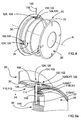
- the figure 1 represents a closed enclosure 10 having a peripheral wall 12 defining a confined interior space 14 and a circular opening 16 allowing the introduction of biopharmaceutical products (not shown) into the confined interior space 14.
- the enclosure 10 - which may be a room or any other similar facility - is designed to be permanently isolated from the outside environment.
- the annular opening 16 is sealed by a removable door 18 positioned in the interior space and capable of passing a closed position in which the circular opening 16 is obstructed to an open position in which the circular opening 16 is no longer obstructed.
- FIGS. 2a and 2b represent a container 20 for transporting biopharmaceutical products and ready to be associated with the closed containment for performing an aseptic transfer of biopharmaceutical products to or from this chamber 10.
- the container 20 comprises, in this respect, a peripheral envelope (not shown) defining a confined interior space 24 into which the biopharmaceutical products can be introduced.
- the peripheral envelope also comprises an annular opening 26 delimited by an annular flange 30 on which the peripheral envelope is firmly fixed.
- the container 20 further comprises a removable cover 28 capable of sealing the opening 24 of the annular flange 30 by resting on a seal 22.
- the container 20 may be made according to different embodiments and, in this regard, have a flexible peripheral envelope and intended for a single use or rigid and intended to be reused after a decontamination procedure well known to those skilled in the art.
- the figures 1 , 2a and 2b illustrate an embodiment of a sealed junction device 40.
- This sealing junction device 40 is intended to allow the aseptic transfer of biopharmaceutical products from the container 20 (described later) to the enclosure 10.
- the purpose of the watertight junction device 40 is therefore first of all to allow the assembly of the enclosure 10 and the container 20, then, to allow the temporary communication of the interior space 14 of the enclosure 10 with the interior space of this container 20 to ensure the transfer of biopharmaceutical products from one towards the other and, finally, to ensure the separation of said enclosure 10 and said container 20.
- the sealing junction device 40 has a portion formed on the outside of the enclosure 10 and supported by the peripheral wall 12 - or by a support piece distinct from the peripheral wall 12 but fixed permanently on it - facing the annular opening 16. More specifically, the sealing junction device 40 comprises an annular functional ring 42 having a face 42a facing the wall device 12 of the enclosure 10 and a face 42b oriented towards the outside environment.
- the annular functional ring 42 also has an inner peripheral periphery 44 INT and an external peripheral periphery 44 EXT inscribed inside three bearing rollers 46 themselves supported by the outer face of the peripheral wall 12. In this way, the crown annular functional 42 is positioned outside the enclosure 10, which facilitates any maintenance operations.
- the three support rollers 46 form, on the one hand, a support for the annular functional ring and allow, on the other hand, its rotation about the geometric axis of the annular opening 16. It should however be emphasized that the maintenance in position of the ring annular functional could be provided by any other similar mechanical element (bearing, bearing, etc.).
- the annular functional ring 42 which has several portions having distinct mechanical functions (described later) is made in one piece - by machining, molding, or the like - from a single block of material.
- This embodiment has the advantage of simplifying the production of the annular functional ring, at the same time reducing the production costs and ensuring optimal positioning of the functional surfaces of the annular functional ring 42.
- the annular functional ring could also, according to other embodiments, be formed from a plurality of separate mechanical parts, assembled together in one piece so that the rotation of one of these mechanical parts around the geometric axis of rotation R between the rotation of all of them.
- the annular functional ring 42 has a stationary rotational driving portion 48 arranged near the outer peripheral periphery of the annular functional ring 42 and formed by teeth 48a radially oriented and capable of being driven by a drive motor 48b placed outside of the enclosure 10 or, according to an alternative embodiment, by a lever (not shown) activated manually. Under the impulse of this drive motor 48b, the annular functional ring is thus capable of being rotated about the geometric axis of rotation R, in a unidirectional direction. By convention, it will be considered later that the unidirectional direction is the clockwise direction. However, alternatively, the direction of rotation of the annular functional ring could also correspond to the counterclockwise direction.
- the sealing junction device 40 comprises temporary stationary clamping means 50.
- the stationary temporary clamping means 50 serve to keep the container 20 flanged against the enclosure 10 so that the removable cover 28 of this container 20 is hermetically applied against the removable door 18 of the enclosure 10.
- These stationary temporary clamping means 50 are mechanically linked to the annular functional ring 42 so that the rotation of this annular functional ring 42 around the geometric axis of rotation R in the clockwise direction mechanically drives the actuation of the stationary clamping means. temporary 50.
- the temporary stationary clamping means 50 comprise four temporary stationary clamping stationary arrangements 52 regularly distributed over the annular functional ring 42. Each of these temporary stationary clamping functional arrangements 52 is formed from a functional clamping crown portion 54. belonging to the annular functional ring 42. Each portion of functional ring forming clamping 54 thus has, on the one hand, an axial clamping functional surface 56 and, on the other hand, an insertion opening 58 of complementary clamping means embedded arranged on a portion of the outer periphery of the container (described later).
- the functional axial clamping surface 56 is formed on the inner peripheral periphery 44 INT of the annular functional ring 42 by an extension of material axially offset from the outer face of the peripheral wall 12 of the enclosure 10 and interrupted regularly to form the
- alternative embodiments providing axial clamping of the annular flange 30 of the container 20 against the outer face of the peripheral wall 12 of the enclosure 10 could also be envisaged.
- the sealing junction device 40 comprises stationary unlocking means 60.
- the stationary unlocking means 60 are intended to move the container 20 from an initial locking position in which the removable cover 28 hermetically closes the container 20 to an intermediate unlocking position in which the removable cover 28 is disengaged from the container and maintained hermetically against the door 18 of the enclosure 10 so as to ensure aseptic communication between the container 20 and the enclosure 10.
- these stationary unlocking means 60 are mechanically linked to the annular functional ring 42 so that the rotation of this annular functional ring 42 around the geometric axis of rotation R and in the clockwise direction mechanically drives the actuation unlocking means 60.
- the actuation of the stationary unlocking means 60 intervenes only after the axial clamping of the container 20 against the enclosure 10.
- the stationary unlocking means 60 comprise several stationary unlocking functional arrangements 62 - in this case four arrangements - regularly distributed around the annular functional ring 42.
- Each of these stationary unlocking functional arrangements 62 comprises, first of all, a functional crown portion 64 forming a radial cam 64 with internal and / or external profile which belongs to the annular functional ring 42.
- the functional crown portion radial cam 64 is formed from a guide path 66 made in the annular functional ring 42, but this embodiment is not limiting.
- Each of these stationary unlocking functional arrangements 62 comprises, secondly, a radial displacement push member 68 capable of cooperating with the radial cam functional crown portion 64.
- a radial displacement push member 68 capable of cooperating with the radial cam functional crown portion 64.
- the pusher element 68 which is fixed in rotation relative to the peripheral wall 12 of the enclosure 10 comprises, in particular, a roller 68a arranged in the guide path 66 and an activation stud 68b connected to the roller 68a so that the displacement of the latter in the radial direction causes a radial movement of the activation pin 68b until the passage of the container 20 in the intermediate unlocking position.
- the sealing junction device 40 comprises stationary locking means 70.
- the stationary locking means 70 are intended to move the container 20 from the intermediate unlocking position to a final locking position in which said removable cover 28 closes, again, the container 20 hermetically.
- these stationary locking means 70 are mechanically linked to the annular functional ring 42 so that the rotation of this annular functional ring 42 around the geometric axis of rotation R and in the clockwise direction mechanically drives the actuation of the means.
- the relative position of the stationary locking means 70 and the stationary unlocking means 60 around the annular functional ring 42 is such that the actuation of these stationary locking means 70 can not be achieved. only after the stopping of the stationary unlocking means 60.
- the stationary locking means 70 comprise four stationary unlocking functional arrangements 72 regularly distributed around the annular functional ring 42.
- Each of these stationary unlocking functional arrangements 72 comprises, firstly, a functional crown portion 74 having an internal and / or external profile which belongs to the annular functional ring 42. As before, this portion of a functional ring forming a cam radial 74 is made from a guide path 76 made in the annular functional ring 42, but this embodiment is not limiting.
- Each of these stationary unlocking functional arrangements 72 then comprises a radial displacement push member 78 capable of cooperating with the radial cam functional crown portion 74.
- a radial displacement push member 78 capable of cooperating with the radial cam functional crown portion 74.
- the pusher element 78 which is fixed in rotation relative to the peripheral wall 12 of the enclosure 10 is the same as the pusher element 68 belonging to the stationary unlocking functional means 60.
- This pusher element 78 thus comprises a roller 68a arranged in the guide path 76 and an activation stud 68b connected to the roller 68a so that the displacement of the latter in the radial direction causes a radial movement of the activation pin 68b, until the passage of the container 20 in the position of intermediate unlocking.
- the radial camming functional crown portion 74 of the stationary locking interlocking arrangement 72 is arranged in the extension of the radial camming functional ring portion 64, the stationary unlocking functional arrangement 62 with respect to the direction of rotation. unidirectional rotation of the annular functional ring 42.
- the radial cam ring portions 72, 62 of the arrangement stationary locking mechanism 74 and the stationary unlocking functional arrangement 62 are formed by a continuous guide path 66, 76 arranged in the annular functional ring 42 and the radial displacement pusher element 68, 78 comprises a roller 68a arranged in the guide path 66, 76 continues so that the rotation of the annular functional ring generates a radial displacement of the roller 68a which causes the corresponding displacement of an activation pin 38b.
- the stationary unlocking means 60 and the stationary locking means 70 could possibly be structurally and functionally distinct and independent of one another.
- the sealing junction device 40 comprises stationary locking / unlocking means 80.
- These stationary locking / unlocking means 80 are intended to prevent / allow the opening of the removable door 18 of the enclosure 10 and are mechanically connected to the annular functional ring 42 so that the unidirectional rotation of this annular functional ring 42 around of the geometrical axis of rotation R and in the clockwise direction mechanically drives the actuation of the stationary locking / unlocking means 80. More particularly, because of the position of these stationary locking / unlocking means 80 on the annular functional ring 42 , these ensure the unlocking of the removable door 18 of the enclosure 10. According to the realization of the figure 1 , the stationary blocking / unlocking means 80 ensure the unlocking of the removable door 18 after the actuation of the stationary unlocking means 60 has led to the container 20 pass to the intermediate unlocking position.
- these stationary locking / unlocking means 80 are arranged on the annular functional ring 42 to ensure the locking of the door removable 18 of the enclosure 10 before the stationary locking means 70 have been activated to pass the container 20 in the final locking position.
- the stationary locking / unlocking means 80 on the annular functional ring 42 so that the latter ensure the unlocking of the removable door 18 simultaneously with the passage of the container 20 in position intermediate unlocking, then the blocking of this removable door 18 simultaneously with the passage of the container 20 in the final locking position.
- the stationary locking / unlocking means 80 on the annular functional ring 42 so that the latter ensure, on the one hand, the unlocking of the removable door 18 of the enclosure 10 before the passage the container 20 in the intermediate unlocking position and, secondly, the locking of the removable door 18 of the enclosure 10 after the passage of the container 20 in the final locking position.
- the stationary locking / unlocking means 80 as illustrated by the figure 1 comprise at least one stationary blocking / unlocking functional arrangement 82 formed by a functional ring gear portion 84 belonging to the annular functional ring 42. As such, this functional gear ring portion 84 is positioned outside the ring gear ring portion 42. enclosure 10.
- this functional ring gear portion 84 is notched so as to engrain a rotation shaft 86, passing through the peripheral wall 12 of the enclosure 10 and itself driving a locking member 88 during the unidirectional rotation of the functional ring.
- the blocking member 88 - which is located in the interior space 14 of the enclosure 10 - is arranged to be able to pass from a locked position in which a lap portion 88a prevents the removable door 18 enclosure 10 to open to an unlocked position in which the overlap portion 88a no longer prevents the removable door 18 from opening.
- the sealing junction device 40 also comprises stationary operating means 90.
- These stationary operating means 90 are intended to open and close hermetically the removable door 18 of the enclosure 10.
- the stationary operating means 90 can, according to a first embodiment (not shown), be driven mechanically by the annular functional ring 42.
- the stationary operating means 90 are mechanically connected to the annular functional ring 42 so that the unidirectional rotation of this annular functional ring 42 around the geometric axis of rotation R and in the clockwise direction mechanically drives the actuation of the stationary operating means 90.
- the position of these means Stationary operating 90 on the annular functional ring 42 allows opening the removable door 18 of the enclosure 10 after the passage of the container 20 in the unlocked position, then to close the removable door 18 before the passage of the container 20 in position final lock.
- the stationary operating means 90 are driven by an operating motor 92 slaved to the displacement of the annular functional ring 42.
- These stationary maneuvering means 90 then comprise a rotary arm 94 adapted to move in rotation about a horizontal axis of rotation and a translational arm 96 adapted to move along a horizontal axis.
- the stationary maneuvering means 90 make it possible, thanks to the operating motor 92 to move the removable door 18 of the enclosure 10, first, in an axial direction, and then in a direction substantially perpendicular to the axial direction so that the removable door 18 does not hinder the passage of the biopharmaceutical product during their aseptic transfer between the enclosure 10 and the container 20.
- the stationary temporary clamping means 50, the stationary unlocking means 60, the stationary locking means 70 and possibly the locking / unlocking means 80 and the operating means 90 are mechanically linked. to the annular functional ring 42 and arranged so that the unidirectional rotation of said annular functional ring 42 around the geometric axis of rotation R and in the clockwise direction successively causes the actuation of the stationary temporary clamping means 50 to ensure the maintenance in position of the container 20 against the enclosure 10, then simultaneously or successively the actuation of the stationary unlocking means 60 ensuring the passage to the intermediate unlocking position of the container 20 and the actuation of the stationary locking / unlocking means 80 ensuring the unlocking of the removable door 18 of the enclosure 10, and then simulated momentarily or successively the actuation of the stationary locking / unlocking means 80 ensuring the locking of the removable door 18 of the enclosure 10 and the actuation of the stationary locking means 70 ensuring the passage in the final locking position of the container 20, and again actuating the stationary temporary clamping means 50 of the
- the stationary temporary clamping means 40 are arranged to ensure the positioning of the container 20 and an indexing relative to the other functional means.
- the accumulation of several cumulative functional arrangements on the annular functional ring 42 allows the implementation of a handling cycle of the container 20 by performing only 1 / n turn.
- the embodiment has 4 distinct functional arrangements evenly distributed over the annular functional ring, but it would be possible to include less - namely one, two or three - or to include more.
- the unidirectional rotation of the annular functional ring 42 makes it possible to actuate the temporary stationary clamping, unlocking, locking, locking / unlocking and operating means that this annular functional ring moves in a direction of rotation or in the other.
- the figure 4 shows in more detail an embodiment of a container to be associated with the sealing device according to the invention.
- this container 20 is intended to allow the transport and aseptic transfer of biopharmaceutical products from or to an enclosure 10 provided with the sealing junction device 40 according to the invention.
- the container 20 comprises the annular flange 30 delimiting the annular opening 26, the removable cover 28 adapted to seal the opening 26 of the annular flange 30 and the peripheral envelope integral with the annular flange 30 and defining the confined interior space 24 likely to contain the biopharmaceutical products.
- the container 20 may be rigid or flexible and reusable or to single use depending on the case. By way of example and in no way limiting, it may be a container 20 of any size, such as a pocket, a sheath, a container, a bioreactor, a chute, etc.
- the container 20 also includes onboard temporary clamping means 100.
- These on-board temporary clamping means 100 are arranged on an outer periphery periphery of the annular flange 30 so as to allow temporary clamping of the container 20 by axial locking on the outer face of the peripheral wall 10 of the enclosure 10 via the actuation of the sealed junction device 40.
- the on-board temporary clamping means 100 comprise at least one on-board temporary clamping functional arrangement 102 formed by at least one lug 104, preferably two lugs 104, having an axial axially flush-mounted functional surface 106 able to bear against the surface Stationary functional axial clamping 56 of the sealed junction device 40.
- These lugs 104 may be positioned between the outer face of the peripheral wall 12 of the enclosure 10 and the stationary axial clamping functional surface 56 of the sealing junction device 40. passing, firstly, through one of the introduction openings 58 of this sealing junction device 40 makes it possible axially to block the displacement of the container 20 with respect to the enclosure 10.
- the removable lid 28 of the container 20 When the container 20 is placed flanged against the enclosure 10, the removable lid 28 of the container 20 is held permanently - by magnetization or otherwise - hermetically against the removable door 108 of the enclosure 10. In this way, the outer space confined between the removable cover 28 and the removable door 18 can not escape during aseptic transfer.
- the container 20 also comprises on-board locking / unlocking means 110 of the removable cover 28 on the annular flange 30.
- the onboard locking / unlocking means 110 - whose structure is detailed below - have the function of ensuring the maintenance of the container 20 in three distinct positions.
- the first position is referred to as the initial locking position because the locking / unlocking means 110 prevent the relative displacement of the removable cover 28 with respect to the annular flange 30.
- the second position is supposed to intervene when the annular flange 30 of the container 20 is axially clamped against the peripheral wall 12 of the enclosure 10 and allows the relative displacement of the removable cover 28 vis-à-vis the annular flange 30.
- the third position, qualified position final locking is assumed to occur after the aseptic transfer of the biopharmaceutical products between the container 20 and the enclosure 10 and prohibited, again and reversibly or irreversibly, the relative displacement of the removable cover 28 vis-à-vis the flange ring 30.
- the onboard locking / unlocking means 110 comprise four on-board locking / unlocking functional arrangements uniformly distributed around the annular flange 28 of the cover 30.
- Each onboard locking / unlocking functional arrangement 112 has a through-housing 114 formed in the annular flange 30 and a blind housing 116 formed in the removable cover 28 of the container 20 and in the extension of the through-housing 114.
- Each on-board locking / unlocking functional arrangement 112 also comprises an internally radially positioned pin 118 and an externally positioned pin 120.
- These two pins with internal radial 118 and outer 120 positioning have, according to the embodiment of FIG. figure 4 , an elongated body of cylindrical shape allowing them to be introduced and to move inside the blind housing 116 formed in the removable cover 28, on the one hand, and the through housing 114 arranged in the annular flange 30, d 'somewhere else. It should be noted, however, that the dimensional characteristics and the properties of the outer surface of these pins with internal radial 118 and outer 120 positioning are such that the latter can not move inside the blind housing 116 and through 114 just because of gravity.
- these pins radially internal 118 and outer 120 may have a body of different shape - for example, parallelepiped - to achieve the same result.
- through housing 114, the blind housing 116, the inner radial positioning pin 118 and the externally positioned pin 120 are coaxial and oriented in a radial direction relative to the annular flange 30. More precisely, according to this embodiment, these various elements extend in a substantially radial direction, oriented towards the geometric axis of revolution R. However, according to an alternative embodiment, said through housings 114, blind housing 116, inner radial positioning pin 118 and external radial positioning pin 120 could also be oriented in a slightly inclined direction and forming an angle ⁇ with respect to a radial direction relative to the annular flange 30.
- the blind housing 116 is flush with the through housing 114 but it could also be envisaged to form an intermediate space between the blind housing 116 and the through housing 114 without affecting the confinement and handling of the container 20.
- the internal radial positioning pin 118 When the container 20 is in the initial locking position, as illustrated by the figures 5a , the internal radial positioning pin 118 has an initial internal locking functional portion 118 INT arranged in the blind housing 116 of the removable cover 28 and an initial external locking functional portion 118 EXT arranged in the through housing 114 of the annular flange 30.
- the pin with internal radial positioning 118 prevents the relative displacement of the removable cover 28 with respect to the annular flange 30.
- the pin with external radial positioning 120 is at least partially arranged in the through-housing 114 of the annular flange 30.
- the external radial positioning pin 120 can then have a functional end portion with external radial positioning 122 excluded from the through housing 114. Access to this functional end portion 122 by the stationary unlocking means 60 or locking 70 is thus facilitated .
- this pin with external radial positioning 120 may alternatively have a functional end portion with external radial positioning 122 flush with the outer end emerging from the through housing 114.
- said externally positioned pin 120 can have a radially positioned external functional end portion 122 entirely housed inside the through-housing 114. In this way, the manipulation of Pin 120 externally positioned is almost impossible without the use of a specific tool.
- the internally radially located pin 118 is at least partially arranged in the blind housing 116 of the removable cover 28 and completely excluded from the through-housing 114 of the annular flange 30. In this way, this internally radial pin 118 no longer prohibits the relative displacement of the annular flange 30 and the removable lid 28 of the container 20.
- the external radial positioning pin 120 is at least partially arranged in the through-housing 114 of the annular flange 30 and completely excluded from the blind housing 116 of the removable cover 28.
- the locking pin external radial positioning 120 has no more influence than the pin radial internal positioning 118 on the relative displacement of the removable cover 28 vis-à-vis the annular flange 30 which can freely be detached to allow the aseptic transfer of biopharmaceutical products.
- the functional end portion with external radial positioning 122 of said external radial positioning pin 120 can then either be excluded from the through housing 114, or be flush with the outer end emerging from the through housing 114, or be housed entirely. inside said through housing 114.
- the internal radial positioning pin 118 is entirely arranged inside the blind housing 116 of the removable cover 28 while the external radial positioning pin 120 has a final internal locking functional portion 120 INT arranged in the blind housing 116 of the removable cover 28 and a final external functional locking portion 120 EXT arranged in the through housing 114 of the annular flange 30. Therefore, the blind housing 116 of the removable cover 28 has a length sufficient to accommodate a on the other hand, the inner radial positioning pin 118 and, on the other hand, the internal final locking functional portion 120 INT .
- the pin radial external positioning 120 prohibits the relative displacement of the removable cover 28 vis-à-vis the annular flange 30.
- the external radially positioned functional end portion 122 of said external radial positioning pin 120 can then be excluded from the through housing 114 to facilitate the eventual subsequent reopening of the container 20.
- said functional end portion with external radial positioning 122 may be flush with the outer end emerging from the through housing 114 or be housed entirely within said through housing 114 to limit the risk of subsequent opening of the container 20.
- Such use of the inner radial positioning pins 118 and outer 120 to place the container in the initial locking position, intermediate unlocking and final locking allows to have a blind housing 116 and a through housing 114 to be made in the removable cover 28 and the annular flange 30 by onboard functional locking / unlocking arrangement 112, which limits the risk of contamination due to possible production defects.
- the manipulation of the locking / unlocking means 110 is facilitated to the extent that it is sufficient to move the inner radial positioning pins 118 and outer 120 in a single direction and one and the same direction to pass the container 20 successively from the initial locking position to the intermediate unlocking position, and then to the final locking position.
- the realization and operation of the sealing junction device are thus simplified.
- the inner radial positioning pins 118 and outer 120 have identical lengths, which in particular makes it possible to simplify the production and assembly of the inner and outer radial positioning pins 118 120 on the container since it is then not necessary to distinguish the pins with respect to their respective dimensions.
- these pins with internal radial 118 and outer 120 positioning could also have different lengths.
- the through-housing 114 and the externally-positioned pin 120 have lengths such that, when the on-board locking / unlocking means 110 are in the provisional unlocking position, the externally-positioned pin 120 presents a functional end portion 122 with external radial positioning excluded from the through housing 114.
- This positioning facilitates, in particular, the operation performed by the stationary locking means 70 to move the container 20 from the intermediate unlocking position to the final locking position since the externally positioned pin 120 is accessible without the radial displacement pusher 78 having to move to the interior of the through housing 114.
- the lengths of the pin with external radial positioning 120 and the through-housing 114 are such that, when the on-board locking / unlocking means 110 are in the final locking position, said externally-positioned pin 120 has an extreme portion. 120 functional external radial positioning housed inside the through housing. In this way, when the container is placed in the final locking position, the gripping of the pin radial external positioning 120 is made complex and impractical without a suitable gripping tool. This thus makes it possible to raise the level of safety relating to the sealing of the container 20 in the final locking position.
- the lengths of the external radial positioning pin 120 and the through-housing 114 prefferably be such that, when the on-board locking / unlocking means 110 are in the final locking position, said pin with external radial positioning 120 has a functional end portion with external radial positioning excluded from the through housing.
- Such an embodiment would, on the contrary, facilitate the removal of the external radial positioning pin 120 outside the through housing 114 and obtain a reusable container after its final locking position setting.
- the container 20 also comprises onboard partitioning and protection means 124.
- the embedded partitioning and protection means 124 are arranged on an outer peripheral portion of the annular flange 30 so as to prevent the unexpected manipulation of the on-board locking / unlocking means carried by the annular flange 30.
- the on-board partitioning and protection means 124 comprise four on-board partitioning and protection functional arrangements 126 arranged around the four through-housings 114 so as to prevent the unexpected or deliberate manipulation of the externally-positioned pin 120. when the latter is not fully inserted into the through housing 118 of the annular flange 30.
- Each onboard partitioning and protection functional arrangement 126 is made from two lugs 128, arranged around or on either side of the through-housing 114.
- the lugs 128 have radial dimensions such that, in the position of Provisional locking, the external radial positioning pin 120 does not extend beyond the lugs 128 belonging partitioning means and protection.
- the onboard partitioning and protective functional arrangement 62 could also be made from a bore formed in the annular flange 30, radially oriented and having a diameter greater than the diameter of the through-housing 114.
- Such an embodiment makes it possible to prevent access to the pin with external radial positioning 120 while retaining space around this pin with external radial positioning 120 so as not to complicate the operation of moving the latter by the pins. stationary means for unlocking 60 and locking 70.
- the lugs 104 forming the onboard temporary clamping means 102 and the lugs 128 forming the onboard protection and partitioning means 124 are the same.
- these lugs 104, 108 have, on the one hand, a onboard axial clamping functional surface 56 ensuring the clamping of the container against the peripheral wall 12 of the enclosure 10 and, on the other hand, a form providing protection and partitioning of the external radial positioning pin 120 when n ' is only partially inserted into the through-housing 114.
- Such an embodiment makes it possible to limit the production costs and to simplify the annular flange 30 by limiting the number of lugs to be produced on the outer peripheral periphery of this annular flange 30.
- on-board temporary clamping means 102 and onboard protection and partitioning means 124 structurally and functionally independent of each other, for example using pins 104 for axial clamping and others different lugs for partitioning and protection of externally positioned pins 120.
- the on-board temporary clamping means 100 are arranged to ensure an indexation of the position of the container 20 with respect to the other stationary means belonging to the sealing junction device 40.
- This accumulation of functional arrangements on the annular functional ring 42 allows the implementation of a handling cycle of the container 20 by performing only 1 / n rotation turn with the annular functional ring 42.
- the embodiment comprises four separate functional arrangements regularly distributed on the annular functional ring 42 but it would be possible to include less - namely one, two or three - or to include more.
- This aseptic transfer process consists, in the first place, of having a closed enclosure 10 as described above and supporting a sealing junction device 40 according to the invention.
- This aseptic transfer process consists, secondly, to have a container 20 in the initial locking position as described above.
- the aseptic transfer process then involves placing the container 20 against the peripheral wall 12 of the enclosure 10 by introducing the lugs 104 belonging to the on-board temporary clamping functional arrangement 102 through the insertion openings 58 belonging to the stationary means. temporary bridle 50.
- annular flange 30 of the container 20 is positioned against the peripheral wall 12 of the enclosure 10 and the removable cover 28 - at least partially formed of ferrite - is held tightly in position against the outer face of the removable door 18 at least partially magnetized.
- the aseptic transfer process then consists in generating the rotation of the annular functional ring 42 in the clockwise direction so that the functional ring forming portions 54 clamping are positioned opposite the lugs 104 forming the temporary onboard clamping means and trap these lugs. 104 between the peripheral wall 12 of the enclosure 10 and the functional axial clamping surfaces 56.
- the container 20 is thus held in position by the sealing junction device 40 against the peripheral wall 12 of the enclosure 10.
- the aseptic transfer process then consists in generating the rotation of the annular functional ring 42 in the clockwise direction in order to actuate the actuation of the stationary unlocking means 60. More particularly, the rotation of this annular functional ring 42 in the clockwise direction causes a displacement of the radial displacement pusher element 68 due to the radial position change of the roller 68a in the guide path 66. The activation stud 68b then lowers and pushes the external radial positioning pin 120 and the pin with radial internal positioning 118 at the same time.
- the internal radial positioning pin 118 is then arranged in the blind housing 116 of the removable cover 28 and completely excluded from the through housing 114 of the annular flange 30 and the external radial positioning pin 120 is arranged in the through housing 114 of the annular flange 30 and completely excluded from the blind housing 116 of the removable cover 28.
- the container 20 is in the intermediate unlocking position and the relative displacement of the removable cover 28 opposite the annular flange 30 is possible.
- the aseptic transfer process also consists, simultaneously or successively in the preceding step, in generating the rotation of the annular functional ring 42 in the clockwise direction in order to actuate the stationary locking / unlocking means 80 to release the removable door 18 of the enclosure 10.
- the functional ring gear portions 84 - which are rotated with the annular functional ring gear 42 - engage the rotation shaft 86 and, therefore, the locking member 88 so that the latter does not cover the outer face of the removable door 18 of the enclosure 10.
- the removable door 18 can then be handled freely.
- the aseptic transfer process then consists of driving the stationary operating means 90 to move the removable door 18 of the enclosure 10 and the removable lid of the container to release the annular openings 16, 26 of the enclosure 10 and the container 20. .
- the stationary operating means 90 which can be actuated by the annular functional ring 42 or by a control motor servo-controlled on the position of this annular functional ring 42 - drive in horizontal translation, first, then in rotation about a horizontal axis, then, the removable door 18 of the enclosure 10.
- the removable cover 28 is able to move with respect to the annular flange 30 and to follow the movements of the removable door 18 of the enclosure 10 due to the magnetic force connecting them to each other.
- the enclosure 10 and the container 20 are open to one another while being hermetically isolated from the outside environment.
- the aseptic transfer process then consists of driving the stationary operating means 90 again to hermetically close the annular openings 16, 26 of the enclosure 10 and the container 20.
- the stationary operating means 90 then drive in rotation about a horizontal axis and then in horizontal translation the removable door 18 of the enclosure 10 and the removable cover of the container 20 to put them in the same position as before.
- the enclosure 10 is then sealed again by the removable door 18, both with respect to the exterior and the container 10. And, symmetrically, the container 20 is sealed by the removable cover, so that to the outside only of the enclosure 10.
- the aseptic transfer process then consists in generating the rotation of the annular functional ring 42 in the clockwise direction in order to actuate the stationary locking / unlocking means 80 to block the removable door 18 of the enclosure 10.
- the functional gear ring portions 84 - which are rotated with the annular functional ring 42 - mesh with the rotation shaft 86 and, therefore, the locking member 88 so that the latter covers the outer face of the removable door 18 of the enclosure 10.
- the removable door 18 can no longer be handled freely.
- the aseptic transfer process consists, simultaneously or successively, of the preceding step in generating the rotation of the annular functional ring 42 in the clockwise direction in order to actuate the actuation of the stationary locking means 70. More particularly, the rotation of this annular functional ring 42 in the clockwise direction causes a displacement of the radial displacement pusher element 78 due to the radial position change of the roller 68a in the guide path 76. The activation pin 68b then lowers and comes pushing the external radial positioning pin 120 and the internal radial positioning pin 118 at the same time.
- the internal radial positioning pin 118 is arranged in the blind housing 116 of the removable cover 28 while the externally positioned pin 120 has a final internal locking functional portion 120 INT arranged in the blind housing. 116 of the removable cover 28 and a final external functional portion 120 EXT arranged in the through housing 114 of the annular flange 30.
- the aseptic transfer method therefore consists in generating the rotation of the annular functional ring 42 in the clockwise direction so that the temporary clamping functional crown portions 54 are positioned so that the insertion openings 58 are opposite the lugs 104. forming the temporary onboard clamping means and release them.
- the container 20 in the final locking position can thus be freely withdrawn from the sealing junction device 40.
Landscapes
- Health & Medical Sciences (AREA)
- Life Sciences & Earth Sciences (AREA)
- Chemical & Material Sciences (AREA)
- Engineering & Computer Science (AREA)
- Wood Science & Technology (AREA)
- Zoology (AREA)
- Organic Chemistry (AREA)
- Bioinformatics & Cheminformatics (AREA)
- General Engineering & Computer Science (AREA)
- Biotechnology (AREA)
- General Health & Medical Sciences (AREA)
- Sustainable Development (AREA)
- Clinical Laboratory Science (AREA)
- Molecular Biology (AREA)
- Biochemistry (AREA)
- Biomedical Technology (AREA)
- Microbiology (AREA)
- Genetics & Genomics (AREA)
- Chemical Kinetics & Catalysis (AREA)
- Physics & Mathematics (AREA)
- High Energy & Nuclear Physics (AREA)
- Closures For Containers (AREA)
- Medical Preparation Storing Or Oral Administration Devices (AREA)
- Mechanical Engineering (AREA)
Claims (15)
- Dichtes Verbindungsstück (40), das dazu bestimmt ist, den aseptischen Transfer eines biopharmazeutischen Produktes zwischen einem Raum (10), der mit einer abnehmbaren Tür (18) versehen ist, und einem Behälter (20), der mit einem abnehmbaren Deckel (28) versehen ist, zu gewährleisten, umfassend:- temporär stationäre Flanschmittel (50), die geeignet sind, den angeflanschten Behälter (20) gegen den Raum (10) zu halten, so dass der abnehmbare Deckel (28) des Behälters (20) hermetisch dicht an die abnehmbare Tür (18) des Raums (10) angelegt ist,- stationäre Entriegelungsmittel (60), die geeignet sind, den Behälter (20) von einer ursprünglichen Verriegelungsposition, in der der abnehmbare Deckel (28) den Behälter (20) hermetisch dicht verschließt, in eine Zwischenentriegelungsposition übergehen zu lassen, in der der abnehmbare Deckel (28) von dem Behälter (20) gelöst und hermetisch dicht an die abnehmbare Tür des Raums (10) gehalten wird, um eine aseptische Verbindung zwischen dem Behälter (20) und dem Raum (10) zu gewährleisten;- stationäre Verriegelungsmittel (70), die geeignet sind, den Behälter (20) von der Zwischenentriegelungsposition in eine Endverriegelungsposition übergehen zu lassen, in der der abnehmbare Deckel (28) den Behälter (20) wieder hermetisch dicht verschließt;- einen ringförmigen Funktionskranz (42), der geeignet ist, sich durch Drehung um eine geometrische Drehachse (R) zu bewegen, um die stationären Entriegelungsmittel (60) und die stationären Verriegelungsmittel (70) des Behälters (20) zu betätigen,dadurch gekennzeichnet, dass die temporär stationären Flanschmittel (50), die stationären Entriegelungsmittel (60) und die stationären Verriegelungsmittel (70) mechanisch mit dem ringförmigen Funktionskranz (42) verbunden und derart angeordnet sind, dass die unidirektionale Drehung des ringförmigen Funktionskranzes (42) um die geometrische Drehachse (R) nacheinander zur Betätigung der temporär stationären Flanschmittel (50), die das Halten des Behälters (20) in Position an dem Raum (10) gewährleisten, dann zur Betätigung der stationären Entriegelungsmittel (60), die den Übergang des Behälters (20) in die Zwischenentriegelungsposition gewährleisten, dann zur Betätigung der stationären Verriegelungsmittel (70) des Behälters (20), die den Übergang des Behälters (20) in die Endverriegelungsposition gewährleisten, und zur Betätigung der temporär stationären Flanschmittel (50) des Behälters (20), die die Freigabe des Behälters (20) gewährleisten, führt.
- Dichtes Verbindungsstück (40) nach Anspruch 1, ferner umfassend stationäre Blockier-/Deblockiermittel (80), die geeignet sind, das Öffnen der abnehmbaren Tür (18) des Raums (10) zu verhindern/gestatten, und die mechanisch mit dem ringförmigen Funktionskranz (42) verbunden sind, so dass die unidirektionale Drehung des ringförmigen Funktionskranzes (42) um die geometrische Drehachse (R) nacheinander zur Betätigung der temporär stationären Flanschmittel (50), die das Halten des Behälters (20) in Position an dem Raum (10) gewährleisten, dann gleichzeitig oder nacheinander zur Betätigung der stationären Entriegelungsmittel (60), die den Übergang des Behälters (20) in die Zwischenentriegelungsposition gewährleisten, und zur Betätigung der stationären Blockier-/Deblockiermittel (80), die das Deblockieren der abnehmbaren Tür (18) des Raums (10) gewährleisten, dann zur Betätigung der stationären Verriegelungsmittel (70) des Behälters (20), die den Übergang des Behälters (20) in die Endverriegelungsposition gewährleisten, dann gleichzeitig oder nacheinander zur Betätigung der stationären Blockier-/Deblockiermittel (80), die das Blockieren der abnehmbaren Tür (18) des Raums (10) gewährleisten, und zur Betätigung der stationären Verriegelungsmittel (70), die den Übergang des Behälters (20) in die Endverriegelungsposition gewährleisten, dann zur Betätigung der temporär stationären Flanschmittel (50) des Behälters (20), die die Freigabe des Behälters (20) gegenüber dem Raum (10) gewährleisten, führt.
- Dichtes Verbindungsstück (40) nach Anspruch 2, bei dem die stationären Blockier-/Deblockiermittel (80) mindestens eine stationäre Funktionsanordnung zum Blockieren/Deblockieren (82), die von einem Abschnitt eines Funktionskranzes gebildet ist, der ein Getriebe (84) bildet, und ein Blockierelement (88) umfassen, das geeignet ist, den Abschnitt des Funktionskranzes, der ein Getriebe (84) bildet, durch Eingreifen aufzunehmen, so dass bei der unidirektionalen Drehung des ringförmigen Funktionskranzes (42) das Blockierelement von einer blockierten Position, in der ein Überlappungsabschnitt die abnehmbare Tür (18) des Raums (10) daran hindert, sich zu öffnen, in eine deblockierte Position übergeht, in der der Überlappungsabschnitt die abnehmbare Tür (18) des Raums (10) nicht mehr daran hindert, sich zu öffnen.
- Dichtes Verbindungsstück (40) nach einem der Ansprüche 1 bis 3, bei dem die stationären Entriegelungsmittel (60) mindestens eine stationäre Funktionsanordnung zur Entriegelung (62), die von einem Abschnitt eines Funktionskranzes gebildet ist, der eine radiale Nocke (64) mit Innen-/Außenprofil bildet, und ein Schubelement (68) mit Radialverschiebung umfasst, das mit dem Abschnitt des Funktionskranzes, der eine radiale Nocke (64) bildet, zusammenwirkt, so dass bei der unidirektionalen Drehung des ringförmigen Funktionskranzes (42) bis in eine Zwischenentriegelungsposition sich das Schubelement (68) verschiebt und den Behälter (20) von der ursprünglichen Verriegelungsposition in die Zwischenentriegelungsposition übergehen lässt.
- Dichtes Verbindungsstück (40) nach einem der Ansprüche 1 bis 4, bei dem die stationären Verriegelungsmittel (70) mindestens eine stationäre Funktionsanordnung zur Verriegelung (72) umfassen, die von einem Abschnitt eines Funktionskranzes, der eine radiale Nocke (74) mit Innen- und/oder Außenprofil bildet, und einem Schubelement (78) mit Radialverschiebung gebildet ist, das mit dem Abschnitt des Funktionskranzes, der die radiale Nocke (74) bildet, zusammenwirkt, so dass bei der unidirektionalen Drehung des ringförmigen Funktionskranzes (42) bis in eine Endverriegelungsposition sich das Schubelement (78) verschiebt und den abnehmbaren Deckel (28) des Behälters (20) von der Zwischenentriegelungsposition in die Endverriegelungsposition übergehen lässt.
- Dichtes Verbindungsstück (40) nach einem der Ansprüche 4 und 5, bei dem der Abschnitt eines Funktionskranzes der stationären Verriegelungs- (70) und/oder Entriegelungsmittel (60), der eine radiale Nocke (64, 74) bildet, von einem Führungsweg (66, 76) gebildet ist, der in dem ringförmigen Funktionskranz (42) angeordnet ist, und das Schubelement (68, 78) mit Radialverschiebung der stationären Verriegelungs- (70) und/oder Entriegelungsmittel (60) eine Rolle (68a) umfasst, die in dem Führungsweg (66, 76) angeordnet ist, so dass die Drehung des ringförmigen Funktionskranzes (42) eine Radialverschiebung der Rolle (68a) erzeugt, die die entsprechende Verschiebung eines Betätigungszapfens (68b) nach sich zieht, bei dem vorzugsweise die stationäre Entriegelungsfunktionsanordnung (62) und die stationäre Verriegelungsfunktionsanordnung (72) aus demselben Schubelement (68, 78) mit Radialverschiebung bestehen, bei dem vorzugsweise der Abschnitt des ringförmigen Funktionskranzes der stationären Verriegelungsfunktionsanordnung (72), der eine radiale Nocke (74) bildet, in der Verlängerung des Abschnitts des Funktionskranzes der stationären Entriegelungsfunktionsanordnung (62), der eine radiale Nocke (64) bildet, bei Betrachtung der unidirektionalen Drehrichtung des ringförmigen Funktionskranzes (42) angeordnet ist, bei dem vorzugsweise die eine radiale Nocke (64, 74) bildenden Kranzabschnitte der stationären Verriegelungsfunktionsanordnung (72) und der stationären Entriegelungsfunktionsanordnung (64) von einem durchgehenden Führungsweg (66, 76) gebildet sind, der in dem ringförmigen Funktionskranz (42) angeordnet ist, und das Schubelement (68, 78) mit Radialverschiebung eine Rolle (68a) umfasst, die in dem durchgehenden Führungsweg (66, 76) angeordnet ist, so dass die Drehung des ringförmigen Funktionskranzes (42) eine Radialverschiebung der Rolle erzeugt, die die entsprechende Verschiebung eines Betätigungszapfens (68b) nach sich zieht, bei dem vorzugsweise die stationären Entriegelungsmittel (60) und die stationären Verriegelungsmittel (70) strukturell und funktionell getrennt und voneinander unabhängig sind.
- Verbindungsstück (40) nach einem der Ansprüche 1 bis 6, bei dem die temporär stationären Flanschmittel (50) mindestens eine temporär stationäre Flanschfunktionsanordnung (52) umfassen, die aus einem einen Flansch (54) bildenden Abschnitt eines Funktionskranzes gebildet ist, umfassend einerseits eine axiale Flanschfunktionsfläche (56) und andererseits eine Öffnung (58) zur Einführung von eingebauten komplementären Flanschmitteln, die auf einem Abschnitt der äußeren Peripherie des Behälters (20) angeordnet sind, bei dem vorzugsweise der einen Flansch bildende Abschnitt eines Funktionskranzes auf einem inneren Umfang des ringförmigen Funktionskranzes (42) ausgeführt ist.
- Verbindungsstück (40) nach einem der Ansprüche 1 bis 7, umfassend stationäre Betätigungsmittel der abnehmbaren Tür (18) des Raums (10), die geeignet sind, die abnehmbare Tür (18) des Raums (10) zu öffnen und hermetisch dicht zu verschließen, bei dem vorzugsweise die stationären Betätigungsmittel (90) der abnehmbaren Tür (18) des Raums (10) mechanisch von dem ringförmigen Funktionskranz (42) angetrieben werden, bei dem vorzugsweise die stationären Betätigungsmittel (90) der abnehmbaren Tür (18) des Raums (10) von einem Betätigungsmotor (92) zur Steuerung der Verschiebung des ringförmigen Funktionskranzes (42) angetrieben werden, bei dem vorzugsweise die stationären Betätigungsmittel (90) der abnehmbaren Tür (18) des Raums (10) geeignet sind, die abnehmbare Tür des Raums zuerst in eine Axialrichtung und dann in eine Richtung im Wesentlichen senkrecht auf die Axialrichtung zu verschieben, so dass die Tür den Durchgang des biopharmazeutischen Produktes nicht behindert.
- Verbindungsstück (40) nach einem der Ansprüche 1 bis 8, bei dem der ringförmige Funktionskranz (42), die temporär stationären Flanschmittel (50) des Behälters (20), die stationären Entriegelungsmittel (60) des Behälters (20) und die stationären Verriegelungsmittel (70) des Behälters (20) außerhalb des Raums (10) angeordnet sind.
- Verbindungsstück (40) nach Anspruch 9, insofern er von Anspruch 3 abhängt, bei dem erstens der ein Getriebe (84) bildende Abschnitt des ringförmigen Funktionskranzes der stationären Blockier-/Deblockierfunktionsanordnung (82) außerhalb des Raums (10) angeordnet ist, und zweitens das Blockierelement (88) der stationären Blockier-/Deblockierfunktionsanordnung (82) innerhalb des Raums (10) angeordnet ist, und drittens das Blockierelement (88) durch eine Rotationswelle (86) angetrieben wird, die durch die Umfangswand (12) des Raums (10) hindurchgeht.
- Verbindungsstück (40) nach einem der Ansprüche 1 bis 10, bei dem die temporär stationären Flanschmittel (50) des Behälters (20), die stationären Entriegelungsmittel (60) des Behälters (20) und die stationären Verriegelungsmittel (70) des Behälters (20) jeweils n stationäre Flanschfunktionsanordnung(en) (52), n stationäre Entriegelungsfunktionsanordnung(en) (62), n stationäre Verriegelungsfunktionsanordnung(en) (72), wobei n größer oder gleich 1 ist, umfassen, so dass jeder Verschiebung des ringförmigen Funktionskranzes (42) in Drehung in die unidirektionale Richtung, die sich auf 1/n vollständige Drehung erstreckt, die aufeinanderfolgende Betätigung der temporär stationären Flanschmittel (50) des Behälters (20), die das Halten des Behälters (20) in Position an dem Raum (10) gewährleisten, der stationären Entriegelungsmittel (60) des Behälters (20), die den Übergang des Behälters (20) in die Zwischenentriegelungsposition gewährleisten, der stationären Verriegelungsmittel (70) des Behälters (20), die den Übergang des Behälters (20) in die Endverriegelungsposition gewährleisten, der temporär stationären Flanschmittel (50) des Behälters (20), die die Freigabe des Behälters (20) gewährleisten, entspricht, wobei n vorzugsweise gleich 3 oder 4 ist.
- Einheit, umfassend einen Raum (10) und ein dichtes Verbindungsstück (40), die speziell dazu bestimmt sind, mit einem Behälter (20) zur einmaligen Verwendung verbunden zu werden, der mit einem abnehmbaren Deckel (28) versehen ist, um den aseptischen Transfer eines biopharmazeutischen Produktes zwischen dem Raum (10) und dem Behälter (20) durchzuführen, wobei der Raum (10) eine geschlossene Umfangswand (12) umfasst, in der eine ringförmige Öffnung (16) ausgenommen ist, die durch eine abnehmbare Tür (18) hermetisch dicht verschlossen ist, und bei der das dichte Verbindungsstück (40) nach einem der Ansprüche 1 bis 11 hergestellt ist.
- Einheit nach Anspruch 12, ferner umfassend einen Behälter (20) zur einmaligen Verwendung, der mit einem abnehmbaren Deckel (28) versehen ist.
- Einheit nach Anspruch 13, bei der der Behälter (20) zur einmaligen Verwendung speziell dazu bestimmt ist, den Transport und den aseptischen Transfer eines Produktes, das dem biopharmazeutischen Bereich angehört, zu gewährleisten, und umfasst:- einen ringförmigen Flansch (30), der eine Öffnung (26) begrenzt;- einen abnehmbaren Deckel (28), der geeignet ist, die Öffnung (26) des ringförmigen Flansches (30) hermetisch dicht zu verschließen;- eingebaute Mittel zur Verriegelung/Entriegelung (110) des abnehmbaren Deckels (28) auf dem ringförmigen Flansch (30); und- eine Umfangshülle (22), die mit dem ringförmigen Flansch (30) verbunden ist und einen eingegrenzten Innenraum (24) begrenzt, der geeignet ist, die Produkte, die dem biopharmazeutischen Bereich angehören, aufzunehmen;wobei die eingebauten Verriegelungs-/Entriegelungsmittel (110) mindestens eine eingebaute Funktionsanordnung zur Verriegelung/Entriegelung (112) umfassen, die einerseits von einer Durchgangslagerung (114), die in dem ringförmigen Flansch (30) ausgebildet ist, und einer Scheinlagerung (116), die in dem abnehmbaren Deckel (28) und in der Verlängerung der Durchgangslagerung (114) ausgebildet ist, wenn der abnehmbare Deckel (28) die Öffnung (26) des ringförmigen Flansches (30) hermetisch dicht verschließt, und andererseits von einem Stift zur radial inneren Positionierung (118) und einem Stift zur radial äußeren Positionierung (120) gebildet ist, die geeignet sind, in das Innere der Blindlagerung (116) des abnehmbaren Deckels (28) und der Durchgangslagerung (114) des ringförmigen Flansches (30) eingeführt zu werden und sich in diesen zu verschieben;
wobei der Behälter (20) geeignet ist, sich in einer ursprünglichen Verriegelungsposition zu befinden, in der einerseits der Stift zur radial inneren Positionierung (118) einen inneren Verriegelungsfunktionsabschnitt (118INT), der in der Blindlagerung (116) des abnehmbaren Deckels (28) angeordnet ist, und einen äußeren Verriegelungsfunktionsabschnitt (118EXT) aufweist, der in der Durchgangslagerung (114) des ringförmigen Flansches (30) angeordnet ist, um die relative Verschiebung des abnehmbaren Deckels (28) gegenüber dem ringförmigen Flansch (30) zu untersagen, und andererseits der Stift zur radial äußeren Positionierung (120) zumindest teilweise in der Durchgangslagerung (114) des ringförmigen Flansches (30) angeordnet ist;
wobei der Behälter (20) geeignet ist, sich in einer Zwischenentriegelungsposition zu befinden, in der einerseits der Stift zur radial inneren Positionierung (118) zumindest teilweise in der Blindlagerung (116) des abnehmbaren Deckels (28) angeordnet und zur Gänze aus der Durchgangslagerung (114) des ringförmigen Flansches (30) ausgeschlossen ist, und andererseits der Stift zur radial äußeren Positionierung (120) zumindest teilweise in der Durchgangslagerung (114) des ringförmigen Flansches (30) angeordnet und zur Gänze aus der Blindlagerung (116) des abnehmbaren Deckels (28) ausgeschlossen ist, so dass die relative Verschiebung des abnehmbaren Deckels (28) gegenüber dem ringförmigen Flansch (30) gestattet ist;
wobei der Behälter (20) geeignet ist, sich in einer Endverriegelungsposition zu befinden, in der einerseits der Stift zur radial inneren Positionierung (118) in der Blindlagerung (116) des abnehmbaren Deckels (28) angeordnet ist und andererseits der Stift zur radial äußeren Positionierung (120) einen inneren Funktionsabschnitt zur Endverriegelung (120INT), der in der Blindlagerung (116) des abnehmbaren Deckels (28) angeordnet ist, und einen äußeren Funktionsabschnitt zur Endverriegelung (120EXT) aufweist, der in der Durchgangslagerung (114) des ringförmigen Flansches (30) angeordnet ist, um die relative Verschiebung des abnehmbaren Deckels (28) gegenüber dem ringförmigen Flansch (30) zu untersagen. - Verfahren zum aseptischen Transfer, das dazu bestimmt ist, den aseptischen Transfer eines biopharmazeutischen Produkts zwischen einem Behälter (20) und einem Raum (10), die einer Einheit nach einem der Ansprüche 12 bis 14 angehören, zu gewährleisten, dadurch gekennzeichnet, dass es nacheinander die folgenden Schritte umfasst, darin bestehend:- den Raum (10), das dichte Verbindungsstück (40) und den Behälter (20) verfügbar zu haben;- den Behälter (20) an der Umfangswand (12) des Raums (10) anzuordnen;- ein axiales Anflanschen des ringförmigen Flansches (30) des Behälters (20) an der Umfangswand (12) des Raums (10) durch unidirektionale Drehung des ringförmigen Funktionskranzes (42) durchzuführen;- den Übergang des Behälters (20) von der ursprünglichen Verriegelungsposition in die Zwischenentriegelungsposition durch unidirektionale Drehung des ringförmigen Funktionskranzes (42) zu bewirken;- gleichzeitig die abnehmbare Tür (18) des Raums (10) und den abnehmbaren Deckel (28) des Behälters (20) zu öffnen, wobei der abnehmbare Deckel (28) hermetisch dicht an der abnehmbaren Tür (18) befestigt wird;- auf aseptische Weise ein oder mehrere biopharmazeutische(s) Produkt(e) zwischen dem Behälter (20) und dem Raum (10) zu transferieren;- gleichzeitig die abnehmbare Tür (18) des Raums (10) und den abnehmbaren Deckel (28) des Behälters (20) wieder zu schließen, wobei der abnehmbare Deckel (28) hermetisch dicht an der abnehmbaren Tür (18) befestigt wird;- den Übergang des Behälters (20) von der Zwischenentriegelungsposition in die Endverriegelungsposition durch unidirektionale Drehung des ringförmigen Funktionskranzes (42) zu bewirken;- das axiale Entflanschen des ringförmigen Flansches (30) des Behälters (20) gegenüber der Umfangswand (12) des Raums (10) durch unidirektionale Drehung des ringförmigen Funktionskranzes (42) durchzuführen.
Applications Claiming Priority (2)
| Application Number | Priority Date | Filing Date | Title |
|---|---|---|---|
| FR1157007A FR2978362B1 (fr) | 2011-07-29 | 2011-07-29 | Dispositif de jonction etanche pour le transfert aseptique d'un produit biopharmaceutique entre une enceinte et un conteneur. |
| PCT/FR2012/051664 WO2013017765A1 (fr) | 2011-07-29 | 2012-07-12 | Dispositif de jonction étanche pour le transfert aseptique d'un produit biopharmaceutique entre une enceinte et un conteneur |
Publications (2)
| Publication Number | Publication Date |
|---|---|
| EP2736639A1 EP2736639A1 (de) | 2014-06-04 |
| EP2736639B1 true EP2736639B1 (de) | 2016-02-10 |
Family
ID=46639617
Family Applications (1)
| Application Number | Title | Priority Date | Filing Date |
|---|---|---|---|
| EP12744091.5A Active EP2736639B1 (de) | 2011-07-29 | 2012-07-12 | Dichtes verbindungsstück zum aseptiscen transfer von biopharmazeutischen produkten |
Country Status (5)
| Country | Link |
|---|---|
| US (1) | US9440229B2 (de) |
| EP (1) | EP2736639B1 (de) |
| CN (1) | CN103826748B (de) |
| FR (1) | FR2978362B1 (de) |
| WO (1) | WO2013017765A1 (de) |
Families Citing this family (16)
| Publication number | Priority date | Publication date | Assignee | Title |
|---|---|---|---|---|
| FR3010119A1 (fr) * | 2013-09-03 | 2015-03-06 | Getinge La Calhene | Dispositif de connexion etanche a securite de fonctionnement amelioree |
| FR3010118B1 (fr) | 2013-09-03 | 2016-02-26 | Getinge La Calhene | Enceinte etanche comportant un mecanisme de commande d'ouverture et de fermeture pour un dispositif de connexion etanche entre deux volumes clos |
| FR3010120B1 (fr) * | 2013-09-03 | 2016-03-04 | Getinge La Calhene | Dispositif de connexion etanche entre deux volumes clos comportant des moyens de maintien prealablement a la connexion |
| JP6445845B2 (ja) * | 2014-11-07 | 2018-12-26 | デンコム株式会社 | 二つの異なる環境をもつ第1及び第2移送空間の間の材料移送路を封密的に連結する封密連結構造 |
| WO2016140920A1 (en) * | 2015-03-02 | 2016-09-09 | Delaware Capital Formation, Inc. | Customizable mounting interface for a sealed transfer port |
| DE102016004200A1 (de) * | 2016-04-06 | 2017-10-12 | Atec Pharmatechnik Gmbh | Rapid-Transfer-Port mit linear beweglicher und schwenkbarer Porttür |
| EP3285073A1 (de) * | 2016-08-16 | 2018-02-21 | Sartorius Stedim Biotech GmbH | Automatisierte transporteinheit und system |
| EP3621774A1 (de) | 2017-05-08 | 2020-03-18 | Delaware Capital Formation, Inc. | Zugangsport mit abdeckung |
| FR3071725A1 (fr) * | 2017-10-03 | 2019-04-05 | Sartorius Stedim Fmt Sas | Dispositif de jonction etanche pour le transfert aseptique d’un produit biopharmaceutique entre une enceinte et un conteneur |
| CN108662433A (zh) * | 2018-04-28 | 2018-10-16 | 贵州望江气体有限公司 | 便于维修的高压储气罐 |
| FR3082126B1 (fr) * | 2018-06-11 | 2022-10-28 | Getinge La Calhene | Systeme de transfert pour enceinte etanche comportant un dispositif de connexion etanche avec un volume clos |
| CN109529957B (zh) * | 2018-11-20 | 2021-05-28 | 中国船舶科学研究中心(中国船舶重工集团公司第七0二研究所) | 一种超高压环境模拟装置 |
| FR3095292B1 (fr) * | 2019-04-16 | 2021-05-14 | Getinge La Calhene | Dispositif de connexion etanche entre deux volumes clos a securite amelioree |
| FR3108355B1 (fr) * | 2020-03-23 | 2022-06-03 | Getinge La Calhene | Sous-ensemble pour système de transfert a double porte de fabrication simplifiée |
| FR3123934B1 (fr) * | 2021-06-11 | 2023-04-28 | Getinge La Calhene | Dispositif de connexion étanche a double porte a sécurité renforcée |
| JP1723868S (ja) * | 2021-12-23 | 2022-09-02 | 移送ドア |
Family Cites Families (9)
| Publication number | Priority date | Publication date | Assignee | Title |
|---|---|---|---|---|
| GB2102719B (en) * | 1981-07-17 | 1985-06-12 | Atomic Energy Authority Uk | Posting system |
| GB8729853D0 (en) * | 1987-12-22 | 1988-02-03 | Atomic Energy Authority Uk | Lid system |
| FR2721289B1 (fr) | 1994-06-17 | 1996-08-30 | Idc Isolateur Denominateur | Dispositif de jonction étanche entre deux enceintes isolées d'un milieu extérieur. |
| FR2787235B1 (fr) | 1998-12-11 | 2001-01-19 | Becton Dickinson France | Dispositif de liaison de portes entre deux enceintes isolees du milieu exterieur |
| US6544229B1 (en) * | 2000-05-01 | 2003-04-08 | Baxter International Inc | Linearly motile infusion pump |
| FR2872446A1 (fr) * | 2004-07-02 | 2006-01-06 | Commissariat Energie Atomique | Dispositif de transfert etanche a double porte comportant des organes d'actionnement des portes equipes de hublots |
| US7299950B2 (en) * | 2004-09-03 | 2007-11-27 | Rieke Corporation | Dispensing apparatus |
| US8141731B2 (en) * | 2008-05-27 | 2012-03-27 | Seaquist Closures L.L.C. | Closure with lid and slidable latch system |
| US8919830B2 (en) * | 2008-11-05 | 2014-12-30 | West Pharmaceutical Services, Inc. | Barrier isolator port assembly |
-
2011
- 2011-07-29 FR FR1157007A patent/FR2978362B1/fr not_active Expired - Fee Related
-
2012
- 2012-07-12 EP EP12744091.5A patent/EP2736639B1/de active Active
- 2012-07-12 CN CN201280047122.5A patent/CN103826748B/zh active Active
- 2012-07-12 US US14/234,788 patent/US9440229B2/en active Active
- 2012-07-12 WO PCT/FR2012/051664 patent/WO2013017765A1/fr not_active Ceased
Also Published As
| Publication number | Publication date |
|---|---|
| FR2978362B1 (fr) | 2013-09-13 |
| US20140150924A1 (en) | 2014-06-05 |
| CN103826748A (zh) | 2014-05-28 |
| WO2013017765A1 (fr) | 2013-02-07 |
| US9440229B2 (en) | 2016-09-13 |
| FR2978362A1 (fr) | 2013-02-01 |
| EP2736639A1 (de) | 2014-06-04 |
| CN103826748B (zh) | 2015-06-03 |
Similar Documents
| Publication | Publication Date | Title |
|---|---|---|
| EP2736639B1 (de) | Dichtes verbindungsstück zum aseptiscen transfer von biopharmazeutischen produkten | |
| EP2736638B1 (de) | Behälter zum aseptischen transfer von biopharmazeutischen produkten | |
| EP3042380B1 (de) | Vorrichtung zur bereitstellung einer fluiddichten verbindung in zwei eingeschlossenen volumina mit vorrichtung zum halten vor der verbindung | |
| EP1463614B1 (de) | Verfahren zum anschliessen einer handhabungseinrichtung an eine hülle mit sterilem inhalt | |
| FR3010118A1 (fr) | Enceinte etanche comportant un mecanisme de commande d'ouverture et de fermeture pour un dispositif de connexion etanche entre deux volumes clos | |
| FR3010119A1 (fr) | Dispositif de connexion etanche a securite de fonctionnement amelioree | |
| EP2504102B1 (de) | Gehäuse für dichte verbindungsvorrichtung und aseptische transfervorrichtung | |
| EP0505269A1 (de) | Verfahren und Anlage zum Umladen von Materialien von einem verseuchten Raum in einen zweiten Raum, ohne diesen zu verseuchen | |
| EP0123598B1 (de) | Drehbarer Transport- und Ersatzbehälter für verunreinigte Teile und Ergänzungsetui für diesen Behälter | |
| EP3885041A1 (de) | Unterbaugruppe für ein vereinfachtes transfersystem mit doppelter tür | |
| EP3691787B1 (de) | Vorrichtung mit dichter verbindung zum aseptischen transfer eines biopharmazeutischen produkts zwischen einer kammer und einem behälter | |
| WO2020212283A1 (fr) | Dispositif de connexion etanche entre deux volumes clos a securite amelioree | |
| EP0312460B1 (de) | Vorrichtung zur entkuppelbaren Verbindung zweier dichter Hohlräume | |
| EP2789550B1 (de) | Handhabungs- und Begrenzungshaube, Anwendung zur Handhabung von Probengefäßen für nukleares Material, insbesondere Kernbrennstoffe | |
| WO2024156757A1 (fr) | Bride de cellule amelioree pour systeme de transfert etanche | |
| FR3161502A1 (fr) | Conteneur pour système à double porte à plateau auto-nivelant | |
| EP4655799A1 (de) | Zellenflansch für eine doppelt abgedichtete tür mit reduzierten öffnungskräften |
Legal Events
| Date | Code | Title | Description |
|---|---|---|---|
| PUAI | Public reference made under article 153(3) epc to a published international application that has entered the european phase |
Free format text: ORIGINAL CODE: 0009012 |
|
| 17P | Request for examination filed |
Effective date: 20140204 |
|
| AK | Designated contracting states |
Kind code of ref document: A1 Designated state(s): AL AT BE BG CH CY CZ DE DK EE ES FI FR GB GR HR HU IE IS IT LI LT LU LV MC MK MT NL NO PL PT RO RS SE SI SK SM TR |
|
| DAX | Request for extension of the european patent (deleted) | ||
| REG | Reference to a national code |
Ref country code: DE Ref legal event code: R079 Ref document number: 602012014705 Country of ref document: DE Free format text: PREVIOUS MAIN CLASS: B01L0001020000 Ipc: B67D0007440000 |
|
| GRAP | Despatch of communication of intention to grant a patent |
Free format text: ORIGINAL CODE: EPIDOSNIGR1 |
|
| RIC1 | Information provided on ipc code assigned before grant |
Ipc: B67D 7/44 20100101AFI20150903BHEP Ipc: B01L 1/02 20060101ALI20150903BHEP Ipc: C12M 1/12 20060101ALI20150903BHEP |
|
| INTG | Intention to grant announced |
Effective date: 20150930 |
|
| GRAS | Grant fee paid |
Free format text: ORIGINAL CODE: EPIDOSNIGR3 |
|
| GRAA | (expected) grant |
Free format text: ORIGINAL CODE: 0009210 |
|
| AK | Designated contracting states |
Kind code of ref document: B1 Designated state(s): AL AT BE BG CH CY CZ DE DK EE ES FI FR GB GR HR HU IE IS IT LI LT LU LV MC MK MT NL NO PL PT RO RS SE SI SK SM TR |
|
| REG | Reference to a national code |
Ref country code: GB Ref legal event code: FG4D Free format text: NOT ENGLISH |
|
| REG | Reference to a national code |
Ref country code: AT Ref legal event code: REF Ref document number: 774565 Country of ref document: AT Kind code of ref document: T Effective date: 20160215 Ref country code: CH Ref legal event code: EP |
|
| REG | Reference to a national code |
Ref country code: IE Ref legal event code: FG4D Free format text: LANGUAGE OF EP DOCUMENT: FRENCH |
|
| REG | Reference to a national code |
Ref country code: DE Ref legal event code: R096 Ref document number: 602012014705 Country of ref document: DE |
|
| REG | Reference to a national code |
Ref country code: LT Ref legal event code: MG4D |
|
| REG | Reference to a national code |
Ref country code: FR Ref legal event code: PLFP Year of fee payment: 5 |
|
| REG | Reference to a national code |
Ref country code: NL Ref legal event code: MP Effective date: 20160210 |
|
| REG | Reference to a national code |
Ref country code: AT Ref legal event code: MK05 Ref document number: 774565 Country of ref document: AT Kind code of ref document: T Effective date: 20160210 |
|
| PG25 | Lapsed in a contracting state [announced via postgrant information from national office to epo] |
Ref country code: HR Free format text: LAPSE BECAUSE OF FAILURE TO SUBMIT A TRANSLATION OF THE DESCRIPTION OR TO PAY THE FEE WITHIN THE PRESCRIBED TIME-LIMIT Effective date: 20160210 Ref country code: FI Free format text: LAPSE BECAUSE OF FAILURE TO SUBMIT A TRANSLATION OF THE DESCRIPTION OR TO PAY THE FEE WITHIN THE PRESCRIBED TIME-LIMIT Effective date: 20160210 Ref country code: GR Free format text: LAPSE BECAUSE OF FAILURE TO SUBMIT A TRANSLATION OF THE DESCRIPTION OR TO PAY THE FEE WITHIN THE PRESCRIBED TIME-LIMIT Effective date: 20160511 Ref country code: IT Free format text: LAPSE BECAUSE OF FAILURE TO SUBMIT A TRANSLATION OF THE DESCRIPTION OR TO PAY THE FEE WITHIN THE PRESCRIBED TIME-LIMIT Effective date: 20160210 Ref country code: ES Free format text: LAPSE BECAUSE OF FAILURE TO SUBMIT A TRANSLATION OF THE DESCRIPTION OR TO PAY THE FEE WITHIN THE PRESCRIBED TIME-LIMIT Effective date: 20160210 Ref country code: NO Free format text: LAPSE BECAUSE OF FAILURE TO SUBMIT A TRANSLATION OF THE DESCRIPTION OR TO PAY THE FEE WITHIN THE PRESCRIBED TIME-LIMIT Effective date: 20160510 |
|
| PG25 | Lapsed in a contracting state [announced via postgrant information from national office to epo] |
Ref country code: NL Free format text: LAPSE BECAUSE OF FAILURE TO SUBMIT A TRANSLATION OF THE DESCRIPTION OR TO PAY THE FEE WITHIN THE PRESCRIBED TIME-LIMIT Effective date: 20160210 Ref country code: PT Free format text: LAPSE BECAUSE OF FAILURE TO SUBMIT A TRANSLATION OF THE DESCRIPTION OR TO PAY THE FEE WITHIN THE PRESCRIBED TIME-LIMIT Effective date: 20160613 Ref country code: IS Free format text: LAPSE BECAUSE OF FAILURE TO SUBMIT A TRANSLATION OF THE DESCRIPTION OR TO PAY THE FEE WITHIN THE PRESCRIBED TIME-LIMIT Effective date: 20160610 Ref country code: LT Free format text: LAPSE BECAUSE OF FAILURE TO SUBMIT A TRANSLATION OF THE DESCRIPTION OR TO PAY THE FEE WITHIN THE PRESCRIBED TIME-LIMIT Effective date: 20160210 Ref country code: SE Free format text: LAPSE BECAUSE OF FAILURE TO SUBMIT A TRANSLATION OF THE DESCRIPTION OR TO PAY THE FEE WITHIN THE PRESCRIBED TIME-LIMIT Effective date: 20160210 Ref country code: RS Free format text: LAPSE BECAUSE OF FAILURE TO SUBMIT A TRANSLATION OF THE DESCRIPTION OR TO PAY THE FEE WITHIN THE PRESCRIBED TIME-LIMIT Effective date: 20160210 Ref country code: PL Free format text: LAPSE BECAUSE OF FAILURE TO SUBMIT A TRANSLATION OF THE DESCRIPTION OR TO PAY THE FEE WITHIN THE PRESCRIBED TIME-LIMIT Effective date: 20160210 Ref country code: LV Free format text: LAPSE BECAUSE OF FAILURE TO SUBMIT A TRANSLATION OF THE DESCRIPTION OR TO PAY THE FEE WITHIN THE PRESCRIBED TIME-LIMIT Effective date: 20160210 Ref country code: AT Free format text: LAPSE BECAUSE OF FAILURE TO SUBMIT A TRANSLATION OF THE DESCRIPTION OR TO PAY THE FEE WITHIN THE PRESCRIBED TIME-LIMIT Effective date: 20160210 |
|
| PG25 | Lapsed in a contracting state [announced via postgrant information from national office to epo] |
Ref country code: EE Free format text: LAPSE BECAUSE OF FAILURE TO SUBMIT A TRANSLATION OF THE DESCRIPTION OR TO PAY THE FEE WITHIN THE PRESCRIBED TIME-LIMIT Effective date: 20160210 Ref country code: DK Free format text: LAPSE BECAUSE OF FAILURE TO SUBMIT A TRANSLATION OF THE DESCRIPTION OR TO PAY THE FEE WITHIN THE PRESCRIBED TIME-LIMIT Effective date: 20160210 |
|
| REG | Reference to a national code |
Ref country code: DE Ref legal event code: R097 Ref document number: 602012014705 Country of ref document: DE |
|
| PG25 | Lapsed in a contracting state [announced via postgrant information from national office to epo] |
Ref country code: RO Free format text: LAPSE BECAUSE OF FAILURE TO SUBMIT A TRANSLATION OF THE DESCRIPTION OR TO PAY THE FEE WITHIN THE PRESCRIBED TIME-LIMIT Effective date: 20160210 Ref country code: CZ Free format text: LAPSE BECAUSE OF FAILURE TO SUBMIT A TRANSLATION OF THE DESCRIPTION OR TO PAY THE FEE WITHIN THE PRESCRIBED TIME-LIMIT Effective date: 20160210 Ref country code: SM Free format text: LAPSE BECAUSE OF FAILURE TO SUBMIT A TRANSLATION OF THE DESCRIPTION OR TO PAY THE FEE WITHIN THE PRESCRIBED TIME-LIMIT Effective date: 20160210 Ref country code: SK Free format text: LAPSE BECAUSE OF FAILURE TO SUBMIT A TRANSLATION OF THE DESCRIPTION OR TO PAY THE FEE WITHIN THE PRESCRIBED TIME-LIMIT Effective date: 20160210 |
|
| PLBE | No opposition filed within time limit |
Free format text: ORIGINAL CODE: 0009261 |
|
| STAA | Information on the status of an ep patent application or granted ep patent |
Free format text: STATUS: NO OPPOSITION FILED WITHIN TIME LIMIT |
|
| PG25 | Lapsed in a contracting state [announced via postgrant information from national office to epo] |
Ref country code: BE Free format text: LAPSE BECAUSE OF NON-PAYMENT OF DUE FEES Effective date: 20160731 |
|
| 26N | No opposition filed |
Effective date: 20161111 |
|
| PG25 | Lapsed in a contracting state [announced via postgrant information from national office to epo] |
Ref country code: BG Free format text: LAPSE BECAUSE OF FAILURE TO SUBMIT A TRANSLATION OF THE DESCRIPTION OR TO PAY THE FEE WITHIN THE PRESCRIBED TIME-LIMIT Effective date: 20160510 Ref country code: SI Free format text: LAPSE BECAUSE OF FAILURE TO SUBMIT A TRANSLATION OF THE DESCRIPTION OR TO PAY THE FEE WITHIN THE PRESCRIBED TIME-LIMIT Effective date: 20160210 |
|
| PG25 | Lapsed in a contracting state [announced via postgrant information from national office to epo] |
Ref country code: MC Free format text: LAPSE BECAUSE OF FAILURE TO SUBMIT A TRANSLATION OF THE DESCRIPTION OR TO PAY THE FEE WITHIN THE PRESCRIBED TIME-LIMIT Effective date: 20160210 |
|
| REG | Reference to a national code |
Ref country code: IE Ref legal event code: MM4A |
|
| REG | Reference to a national code |
Ref country code: FR Ref legal event code: PLFP Year of fee payment: 6 |
|
| PG25 | Lapsed in a contracting state [announced via postgrant information from national office to epo] |
Ref country code: IE Free format text: LAPSE BECAUSE OF NON-PAYMENT OF DUE FEES Effective date: 20160712 |
|
| PG25 | Lapsed in a contracting state [announced via postgrant information from national office to epo] |
Ref country code: LU Free format text: LAPSE BECAUSE OF NON-PAYMENT OF DUE FEES Effective date: 20160712 |
|
| PG25 | Lapsed in a contracting state [announced via postgrant information from national office to epo] |
Ref country code: CY Free format text: LAPSE BECAUSE OF FAILURE TO SUBMIT A TRANSLATION OF THE DESCRIPTION OR TO PAY THE FEE WITHIN THE PRESCRIBED TIME-LIMIT Effective date: 20160210 Ref country code: HU Free format text: LAPSE BECAUSE OF FAILURE TO SUBMIT A TRANSLATION OF THE DESCRIPTION OR TO PAY THE FEE WITHIN THE PRESCRIBED TIME-LIMIT; INVALID AB INITIO Effective date: 20120712 |
|
| REG | Reference to a national code |
Ref country code: FR Ref legal event code: PLFP Year of fee payment: 7 |
|
| PG25 | Lapsed in a contracting state [announced via postgrant information from national office to epo] |
Ref country code: MT Free format text: LAPSE BECAUSE OF FAILURE TO SUBMIT A TRANSLATION OF THE DESCRIPTION OR TO PAY THE FEE WITHIN THE PRESCRIBED TIME-LIMIT Effective date: 20160210 Ref country code: MK Free format text: LAPSE BECAUSE OF FAILURE TO SUBMIT A TRANSLATION OF THE DESCRIPTION OR TO PAY THE FEE WITHIN THE PRESCRIBED TIME-LIMIT Effective date: 20160210 |
|
| PG25 | Lapsed in a contracting state [announced via postgrant information from national office to epo] |
Ref country code: AL Free format text: LAPSE BECAUSE OF FAILURE TO SUBMIT A TRANSLATION OF THE DESCRIPTION OR TO PAY THE FEE WITHIN THE PRESCRIBED TIME-LIMIT Effective date: 20160210 Ref country code: TR Free format text: LAPSE BECAUSE OF FAILURE TO SUBMIT A TRANSLATION OF THE DESCRIPTION OR TO PAY THE FEE WITHIN THE PRESCRIBED TIME-LIMIT Effective date: 20160210 |
|
| P01 | Opt-out of the competence of the unified patent court (upc) registered |
Effective date: 20230517 |
|
| REG | Reference to a national code |
Ref country code: DE Ref legal event code: R081 Ref document number: 602012014705 Country of ref document: DE Owner name: SARTORIUS STEDIM FMT, FR Free format text: FORMER OWNER: SARTORIUS STEDIM FMT SAS, AUBAGNE, FR Ref country code: DE Ref legal event code: R081 Ref document number: 602012014705 Country of ref document: DE Owner name: SARTORIUS STEDIM, FR Free format text: FORMER OWNER: SARTORIUS STEDIM FMT SAS, AUBAGNE, FR |
|
| REG | Reference to a national code |
Ref country code: DE Ref legal event code: R081 Ref document number: 602012014705 Country of ref document: DE Owner name: SARTORIUS STEDIM FMT, FR Free format text: FORMER OWNER: SARTORIUS STEDIM, AUBAGNE, FR |
|
| PGFP | Annual fee paid to national office [announced via postgrant information from national office to epo] |
Ref country code: DE Payment date: 20250722 Year of fee payment: 14 |
|
| PGFP | Annual fee paid to national office [announced via postgrant information from national office to epo] |
Ref country code: GB Payment date: 20250724 Year of fee payment: 14 |
|
| PGFP | Annual fee paid to national office [announced via postgrant information from national office to epo] |
Ref country code: FR Payment date: 20250723 Year of fee payment: 14 |
|
| PGFP | Annual fee paid to national office [announced via postgrant information from national office to epo] |
Ref country code: CH Payment date: 20250801 Year of fee payment: 14 |