EP2736733B1 - Fahrwerksystem für nutzfahrzeuge - Google Patents
Fahrwerksystem für nutzfahrzeuge Download PDFInfo
- Publication number
- EP2736733B1 EP2736733B1 EP12781084.4A EP12781084A EP2736733B1 EP 2736733 B1 EP2736733 B1 EP 2736733B1 EP 12781084 A EP12781084 A EP 12781084A EP 2736733 B1 EP2736733 B1 EP 2736733B1
- Authority
- EP
- European Patent Office
- Prior art keywords
- axle
- recess
- link
- fastening portion
- link element
- Prior art date
- Legal status (The legal status is an assumption and is not a legal conclusion. Google has not performed a legal analysis and makes no representation as to the accuracy of the status listed.)
- Not-in-force
Links
- 239000012790 adhesive layer Substances 0.000 claims description 41
- 238000000034 method Methods 0.000 claims description 21
- 238000004519 manufacturing process Methods 0.000 claims description 9
- 239000003822 epoxy resin Substances 0.000 claims description 3
- 229920000647 polyepoxide Polymers 0.000 claims description 3
- 229920001296 polysiloxane Polymers 0.000 claims description 2
- 239000004814 polyurethane Substances 0.000 claims description 2
- 229920002635 polyurethane Polymers 0.000 claims description 2
- 230000005540 biological transmission Effects 0.000 claims 1
- 239000000356 contaminant Substances 0.000 claims 1
- 239000000463 material Substances 0.000 description 20
- 239000000725 suspension Substances 0.000 description 16
- 238000003466 welding Methods 0.000 description 8
- 230000007797 corrosion Effects 0.000 description 6
- 238000005260 corrosion Methods 0.000 description 6
- 238000006073 displacement reaction Methods 0.000 description 4
- 238000003780 insertion Methods 0.000 description 4
- 230000037431 insertion Effects 0.000 description 4
- 229910052751 metal Inorganic materials 0.000 description 4
- 239000002184 metal Substances 0.000 description 4
- 238000005096 rolling process Methods 0.000 description 4
- 238000005452 bending Methods 0.000 description 3
- 230000002349 favourable effect Effects 0.000 description 3
- 229910000831 Steel Inorganic materials 0.000 description 2
- 239000000853 adhesive Substances 0.000 description 2
- 230000001070 adhesive effect Effects 0.000 description 2
- 229910052782 aluminium Inorganic materials 0.000 description 2
- XAGFODPZIPBFFR-UHFFFAOYSA-N aluminium Chemical compound [Al] XAGFODPZIPBFFR-UHFFFAOYSA-N 0.000 description 2
- 238000005266 casting Methods 0.000 description 2
- 239000003344 environmental pollutant Substances 0.000 description 2
- 230000035515 penetration Effects 0.000 description 2
- 231100000719 pollutant Toxicity 0.000 description 2
- 239000010959 steel Substances 0.000 description 2
- 230000035882 stress Effects 0.000 description 2
- 229910000838 Al alloy Inorganic materials 0.000 description 1
- 238000007906 compression Methods 0.000 description 1
- 238000010276 construction Methods 0.000 description 1
- 238000001816 cooling Methods 0.000 description 1
- 230000001419 dependent effect Effects 0.000 description 1
- 239000012895 dilution Substances 0.000 description 1
- 238000010790 dilution Methods 0.000 description 1
- 239000000975 dye Substances 0.000 description 1
- 239000012530 fluid Substances 0.000 description 1
- 239000000446 fuel Substances 0.000 description 1
- 238000003754 machining Methods 0.000 description 1
- 238000002844 melting Methods 0.000 description 1
- 230000008018 melting Effects 0.000 description 1
- 150000002739 metals Chemical class 0.000 description 1
- 229910000510 noble metal Inorganic materials 0.000 description 1
- 230000000149 penetrating effect Effects 0.000 description 1
- 239000000243 solution Substances 0.000 description 1
- 238000003860 storage Methods 0.000 description 1
- 230000008961 swelling Effects 0.000 description 1
- 230000008646 thermal stress Effects 0.000 description 1
Images

Classifications
-
- B—PERFORMING OPERATIONS; TRANSPORTING
- B60—VEHICLES IN GENERAL
- B60G—VEHICLE SUSPENSION ARRANGEMENTS
- B60G9/00—Resilient suspensions of a rigid axle or axle housing for two or more wheels
- B60G9/003—Resilient suspensions of a rigid axle or axle housing for two or more wheels the axle being rigidly connected to a trailing guiding device
-
- B—PERFORMING OPERATIONS; TRANSPORTING
- B60—VEHICLES IN GENERAL
- B60G—VEHICLE SUSPENSION ARRANGEMENTS
- B60G21/00—Interconnection systems for two or more resiliently-suspended wheels, e.g. for stabilising a vehicle body with respect to acceleration, deceleration or centrifugal forces
- B60G21/02—Interconnection systems for two or more resiliently-suspended wheels, e.g. for stabilising a vehicle body with respect to acceleration, deceleration or centrifugal forces permanently interconnected
- B60G21/04—Interconnection systems for two or more resiliently-suspended wheels, e.g. for stabilising a vehicle body with respect to acceleration, deceleration or centrifugal forces permanently interconnected mechanically
- B60G21/05—Interconnection systems for two or more resiliently-suspended wheels, e.g. for stabilising a vehicle body with respect to acceleration, deceleration or centrifugal forces permanently interconnected mechanically between wheels on the same axle but on different sides of the vehicle, i.e. the left and right wheel suspensions being interconnected
- B60G21/051—Trailing arm twist beam axles
-
- B—PERFORMING OPERATIONS; TRANSPORTING
- B60—VEHICLES IN GENERAL
- B60G—VEHICLE SUSPENSION ARRANGEMENTS
- B60G7/00—Pivoted suspension arms; Accessories thereof
- B60G7/001—Suspension arms, e.g. constructional features
-
- B—PERFORMING OPERATIONS; TRANSPORTING
- B60—VEHICLES IN GENERAL
- B60G—VEHICLE SUSPENSION ARRANGEMENTS
- B60G2200/00—Indexing codes relating to suspension types
- B60G2200/30—Rigid axle suspensions
- B60G2200/31—Rigid axle suspensions with two trailing arms rigidly connected to the axle
-
- B—PERFORMING OPERATIONS; TRANSPORTING
- B60—VEHICLES IN GENERAL
- B60G—VEHICLE SUSPENSION ARRANGEMENTS
- B60G2204/00—Indexing codes related to suspensions per se or to auxiliary parts
- B60G2204/10—Mounting of suspension elements
- B60G2204/14—Mounting of suspension arms
- B60G2204/148—Mounting of suspension arms on the unsprung part of the vehicle, e.g. wheel knuckle or rigid axle
-
- B—PERFORMING OPERATIONS; TRANSPORTING
- B60—VEHICLES IN GENERAL
- B60G—VEHICLE SUSPENSION ARRANGEMENTS
- B60G2206/00—Indexing codes related to the manufacturing of suspensions: constructional features, the materials used, procedures or tools
- B60G2206/01—Constructional features of suspension elements, e.g. arms, dampers, springs
- B60G2206/20—Constructional features of semi-rigid axles, e.g. twist beam type axles
-
- B—PERFORMING OPERATIONS; TRANSPORTING
- B60—VEHICLES IN GENERAL
- B60G—VEHICLE SUSPENSION ARRANGEMENTS
- B60G2206/00—Indexing codes related to the manufacturing of suspensions: constructional features, the materials used, procedures or tools
- B60G2206/01—Constructional features of suspension elements, e.g. arms, dampers, springs
- B60G2206/30—Constructional features of rigid axles
-
- B—PERFORMING OPERATIONS; TRANSPORTING
- B60—VEHICLES IN GENERAL
- B60G—VEHICLE SUSPENSION ARRANGEMENTS
- B60G2206/00—Indexing codes related to the manufacturing of suspensions: constructional features, the materials used, procedures or tools
- B60G2206/01—Constructional features of suspension elements, e.g. arms, dampers, springs
- B60G2206/50—Constructional features of wheel supports or knuckles, e.g. steering knuckles, spindle attachments
-
- B—PERFORMING OPERATIONS; TRANSPORTING
- B60—VEHICLES IN GENERAL
- B60G—VEHICLE SUSPENSION ARRANGEMENTS
- B60G2206/00—Indexing codes related to the manufacturing of suspensions: constructional features, the materials used, procedures or tools
- B60G2206/01—Constructional features of suspension elements, e.g. arms, dampers, springs
- B60G2206/80—Manufacturing procedures
- B60G2206/82—Joining
- B60G2206/8209—Joining by deformation
-
- B—PERFORMING OPERATIONS; TRANSPORTING
- B60—VEHICLES IN GENERAL
- B60G—VEHICLE SUSPENSION ARRANGEMENTS
- B60G2206/00—Indexing codes related to the manufacturing of suspensions: constructional features, the materials used, procedures or tools
- B60G2206/01—Constructional features of suspension elements, e.g. arms, dampers, springs
- B60G2206/80—Manufacturing procedures
- B60G2206/82—Joining
- B60G2206/821—Joining by gluing
-
- Y—GENERAL TAGGING OF NEW TECHNOLOGICAL DEVELOPMENTS; GENERAL TAGGING OF CROSS-SECTIONAL TECHNOLOGIES SPANNING OVER SEVERAL SECTIONS OF THE IPC; TECHNICAL SUBJECTS COVERED BY FORMER USPC CROSS-REFERENCE ART COLLECTIONS [XRACs] AND DIGESTS
- Y10—TECHNICAL SUBJECTS COVERED BY FORMER USPC
- Y10T—TECHNICAL SUBJECTS COVERED BY FORMER US CLASSIFICATION
- Y10T29/00—Metal working
- Y10T29/49—Method of mechanical manufacture
- Y10T29/49616—Structural member making
- Y10T29/49622—Vehicular structural member making
Definitions
- the present invention relates to a chassis system for commercial vehicles according to claim 1.
- the vehicle axle for a commercial vehicle is usually mounted resiliently on the vehicle frame via one or more link elements and spring elements, wherein the connection between the link element or elements and the vehicle axle is preferably produced by means of welding methods.
- a disadvantage of welding processes is that structural disturbances and material stresses can occur due to the high local temperature input into the link element and the vehicle axle.
- the frictional connection of the vehicle axle and link element in particular by widening of the vehicle axle in the region of the link element known, but the frictional connection is often not sufficient to the high torsional and bending moments acting on the link member and the vehicle axle to be able to transmit.
- WO 2009/053491 and WO 2008/055958 discloses a relevant driving system of the prior art.
- Object of the present invention is to provide a suspension system, which is easy to manufacture and meets the strength requirements for use in commercial vehicles.
- the chassis system for commercial vehicles comprises a stub axle element and a link element, wherein the link element has a recess and the stub axle element has a first attachment portion, wherein the first attachment portion is arranged in the recess of the link element and is frictionally secured to the recess due to a forming operation and wherein between the the first attachment portion and the recess is provided an adhesive layer, via which a material connection between the first attachment portion of the axle stub element and the recess of the link member is formed.
- the Achsstummelement is preferably formed at least partially rotationally symmetrical and serves primarily to rotatably support other components of the suspension system.
- the stub axle element particularly preferably has areas or surfaces on which rolling elements of a roller bearing can roll, in order, for example, to rotatably support the rotatable hub of the vehicle wheel of a utility vehicle on the chassis system.
- the axle stub element has a first fastening section, by means of which the axle stub element can be fixed in a recess of the link element.
- the first attachment portion of the stub axle also designed rotationally symmetrical, for example as a hollow body or tubular, and in particular preferably has an outer contour which substantially corresponds to the inner contour of the recess of the link element and can be inserted into this.
- both the outer contour of the first attachment portion of the stub axle and the inner contour of the recess of the link element is square or cuboid, or has a rectangular cross-section, in this preferred embodiment, the Achsstummelement is positively secured against rotation relative to the link element.
- the first attachment portion is at least partially reshaped such that a non-positive connection between the first attachment portion and the recess of the link member is formed.
- the first attachment portion after insertion into the recess is widened such that the outer contour of the first attachment portion pressed against the inner contour of the recess of the link member and the stub axle is connected in this way non-positively with the link member.
- a hydroforming process abbreviated hydroforming
- an adhesive layer is provided between the first attachment section and the recess in order to produce a material bond between the two opposing surfaces of the first attachment section and the axle stub element.
- the adhesive layer produces an adhesive bond between the link member and the stub axle member.
- the adhesive layer not only strengthens the connection between the link element and the axle stub element, but also prevents the penetration of moisture or pollutants into the contact area between the link element and stub axle element.
- the life or the service life of the non-positive or cohesive connection of the link element and stub axle element can be increased.
- the axle stub element is made in one piece. In this way, the number of parts to be assembled and thus the assembly of the entire suspension system can be reduced.
- the axle stub element is advantageously produced with as few method steps as possible, for example, casting and then post-machining, or rolling.
- an axle tube element which is fixed to the handlebar element, in particular to increase the stability of the chassis system.
- the axle tube element is preferably a tubular component which extends longitudinally along an axial direction and in particular preferably connects two opposing link elements with one another.
- the axle tube element is preferably the rigid axle in the chassis of a utility vehicle.
- the Achsrohrelement is fixed at a distal end in the axial direction on the link element, wherein the axial direction of the Achsrohrettis not necessarily coaxially aligned with the axial direction of the Achsstummelettis.
- the Achsrohrelement is so firmly connected to the link member that it receives bending moments, which are transmitted from the wheels via the stub axle member to the link member, and the link member secures against rotation transversely to the axial direction.
- the Achsrohrelement is fixed directly to the axle stub, or its, the preferred receiving areas for rolling bearing remote, distal end, wherein for fixing the Achsrohrides on the axle stub a Reibsch wait snake can be advantageously used.
- the axle tube element is non-positively and / or firmly bonded to the link element.
- fix the Achsrohrelement means of a non-positive connection on the link element, which by the application of an adhesive layer in the contact area between the two elements by a cohesive Connection is supported.
- the link element preferably has a second recess into which a first attachment region of the axle tube element can be introduced, wherein this first attachment region can be fastened non-positively to the second recess of the link element by expansion, for example by means of hydroforming.
- first attachment region can be fastened non-positively to the second recess of the link element by expansion, for example by means of hydroforming.
- the frictional connection between Achsrohrelement and link element can be particularly preferably supported by the use of an adhesive layer and a cohesive connection formed by them.
- the axle tube element can also be fixed to the handlebar element by a purely cohesive connection, for example a rotary friction-welded connection or vibration-friction welding connection.
- the stub axle element is transverse to a main axis of extension of the axle tube element with respect to the axle tube element staggered arranged to frictionally connect the other element by a forming operation on the link element in existing connection between one of the two elements with the link element.
- both elements are preferably provided transversely to the axial direction or to the main extension axis of the Achsrohrettis offset from each other on the handlebar element or arranged.
- axle stub element or the axle tube element is inserted into the recess of the link element with the respective first attachment section and if, for example, a mandrel is inserted in the direction opposite to the insertion direction, which in turn expands the respective one reached first attachment portion.
- the Achsrohrelement and the stub axle element in their respective first mounting portions on the same geometric properties, so that only a forming machine or only a mandrel which is inserted for forming by means of a press in the respective mounting portion, both for the determination of the Achsstummelelements can be used as well as for the determination of the axle tube element on the handlebar element.
- machine and tool costs can be saved in this way.
- a carrier element which can be fixed to the axle tube element and / or to the axle stub element and / or to the link element in order to fix additional suspension elements on the chassis system.
- the support member may for example be a brake carrier to which a brake disc, a brake cylinder and other systems of the suspension of a commercial vehicle can be fixed.
- the carrier element for receiving higher moments not only on an element, so for example, the Achsrohr- or stub axle is set, but over a variety can be fixed by contact or attachment points both on Achsrohrelement and on the stub axle or on the handlebar element.
- the carrier element is designed plate-shaped and has a main extension direction, which is aligned substantially transversely to the axial direction of the Achsrohrides and the Achsstummelettis.
- the carrier element has a recess in which a second attachment portion of the Achsrohrelements or a second attachment portion of the Achsstummelelements is einpressbar, wherein between the recess of the support member and the respective second attachment portion is provided a further adhesive layer to a material bond between the support element and one of the elements Achsrohrelement or Achsstummelelement to form.
- the carrier element is fixed to one of the elements Achsrohrelement or Achsstummelelement via a non-positive and reinforced by an adhesive layer cohesive connection.
- the axle tube element and / or the stub axle element have a second attachment section, which is inserted in a recess of the carrier element and is subsequently expanded by means of a forming method.
- Analogous to the provided between axle stub element and link element adhesive layer can also be applied to the second attachment portion an adhesive layer which produces a cohesive connection to the recess of the support member upon expansion of the second attachment portion and in turn prevents the penetration of corrosion-promoting foreign matter.
- the carrier element is provided on the axle stub element, wherein particularly preferably the second attachment portion of the axle stub element is arranged in the vicinity of the bearing areas for the corresponding wheel bearing of the axle stub element. This serves, in particular, to be able to support the other systems of the chassis system via the carrier element near the wheel, which is rotatably arranged on the axle stub element.
- the link element is pivotally attached to the frame of a commercial vehicle at a first distal end, wherein the link element at a second, opposite the first end, distal end has a receiving area to support a spring element and forces from the spring element to the Achsrohrelement and / or to transfer the stub axle element.
- the link element is preferably the axle link of the chassis system of a utility vehicle, the latter extending substantially parallel to the vehicle longitudinal direction.
- the link element is preferably secured via a bearing eye or a bearing bush against displacement relative to the vehicle frame and pivotally attached to an example bearing block, wherein the axis of rotation of the pivoting movement particularly preferably transversely to the vehicle longitudinal direction and parallel to the axial direction of the vehicle axle or Achsrohrelements is aligned.
- the link element is preferably mounted on a spring element, for example a spiral spring or an air spring, via a receiving region, this spring element essentially serving to cause the pivoting movement of the link element towards a rest position ,
- a spring element for example a spiral spring or an air spring
- this spring element essentially serving to cause the pivoting movement of the link element towards a rest position
- the recess which is in engagement with the axle stub element, provided on the handlebar element.
- the link element is kept as short or as compact as possible in order to save both required space and weight, in a particularly preferred manner, the receiving area for the spring element and the recess in which the stub axle engages arranged as close to each other are. It should be noted here, however, that in a very short link element in a compression process of the spring element, the pivotal movement of the link element a strong circular-shaped movement the receiving area of the link element has the consequence, wherein the spring or the spring element is not only deformed in the vertical direction, but can also experience a strong deformation in the vehicle longitudinal direction.
- the adhesive layer is formed by means of a polyurethane or an epoxy resin or a silicone.
- a polyurethane or an epoxy resin or a silicone is particularly preferred.
- an epoxy resin is particularly preferred because it achieves particularly high strength values when a metal is combined with another metal.
- the axle stub element and / or the Achsrohrelement is reshaped such that at least one undercut is formed, through which a positive connection between the first mounting portion and the recess of the link member is made.
- an undercut is formed, which produces a form fit, which prevents in particular displacements of the Achsstummelements or the Achsrohrelements along the axial direction relative to the link element.
- the widening of the stub axle element or the axle tube element in the areas shortly before and shortly after contact with the link element can be allowed in such a way that a slight buckling of the Achsrohremias takes place in the first attachment portion and in this way the Achsrohrelement is positively fixed to the handlebar element.
- the adhesive layer is distributed in such a way in the contact area of the respective corresponding components that moisture and moisture Pollutants in the contact area is prevented.
- the adhesive layer which is preferably used when fixing the stub axle element, the axle tube element and the carrier element on the handlebar element, should preferably also prevent moisture and dyes from penetrating into the contact region of the respective elements or components.
- the annular space which forms between the respective first fastening sections and the respective recesses corresponding thereto, is preferably sealed at its end faces by the adhesive layer.
- a chassis system for commercial vehicles which comprises an axle stub element and a link element, wherein the link element has a recess and the axle stub element has a first attachment section, wherein in a first state the first attachment section of the axle stub element can be inserted with an adhesive layer into the recess of the link element is, wherein in a second state, the first attachment portion is deformed such that a frictional connection between the first attachment portion and the recess is present, wherein in the second state by means of an adhesive layer, a material connection between the first attachment portion and the recess is formed.
- the first state is preferably the state before connecting the Achsstummelements on the handlebar element.
- the axle stub element has a first attachment portion, which is shaped such that it can be inserted into the recess on the handlebar element.
- a method for producing a chassis system for commercial vehicles comprising the steps of providing a stub axle element and a link element, wherein the axle stub element has a first attachment portion and wherein the link element has a recess into which the first attachment portion is insertable; Applying an adhesive layer to the first attachment portion of the axle stub element; Inserting the first attachment portion into the recess of the link member; Forming, in particular expansion, of the first fastening section, to establish a frictional connection between the first attachment portion and the recess and a material bond between the first attachment portion of the adhesive layer and the recess of the link member.
- the inventive method for producing a suspension system is characterized in that a non-positive or cohesive connection between the stub axle and the link member is made, in particular preferably the disadvantages of a purely material connection, which is produced for example by a welding process, be avoided.
- Such disadvantages may be that during the welding process and the required high temperatures disturbances in the structure of the respective manufacturing materials of the link element and the Achsstummelelements may occur and that upon cooling after the welding process significant thermal stresses in the joined components, the strength and thus the reliability of the suspension system considerably can worsen.
- the first attachment portion of the axle stub element is designed such that it can be easily inserted into the recess of the link member, particularly preferably corresponds to the outer geometry of the first attachment portion at least partially with the internal geometry of the recess on the link element.
- the axle stub element is aligned in a desired position to the link element. This is particularly preferred if further non-rotationally symmetrical parts are already provided on the axle stub element, for example a carrier element to which brakes or similar secondary systems of the chassis system can be secured.
- the first attachment portion of the axle stub element is reshaped, in particular preferably expanded, to produce a frictional connection between the outer contour of the attachment portion and the inner contour of the recess of the link element.
- the outer surface of the attachment portion is displaced against the inner surface of the recess of the link member during the forming process and pressed onto this, wherein the located between the two surfaces Adhesive layer as evenly as possible between the two, distributed to each other moving surfaces, and achieved with the smallest possible gap thickness between the two surfaces maximum adhesion.
- the adhesive layer produces a material bond between the respective corresponding elements.
- a Achsrohrelement is provided, which is arranged with a first attachment portion in a recess of the link member and reshaped such that a frictional connection between the first attachment portion of the Achsrohrelements and the link element is formed, wherein via an adhesive layer a material bond between the first attachment portion and the handlebar element is manufactured.
- the link member is a casting and has a geometry that is particularly suitable for ensuring a favorable flow of force from the receiving point of the stub axle to the receiving area for the spring element or towards the recess in which engages the Achsrohrelement.
- the link element is made of an aluminum alloy.
- the inventive adhesive joint of the stub axle element and the handlebar element made of aluminum proves to be particularly advantageous, since it is generally preferred to use steel for the stub axle element, wherein the occurring in a metal-metal compound of steel with aluminum contact corrosion and similar intermetallurgical wear processes by the Adhesive layer can be prevented.
- the use of the adhesive layer preferably makes it possible to separate the two metal surfaces from one another in order to prevent the so-called galvanic corrosion. This corrosion or corrosion process arises in particular when different metals brought into contact with each other are due to the different electrical potentials corrodes the less noble metal.
- Fig. 1 a preferred embodiment of the chassis system according to the invention is shown, which comprises the components link element 4, axle stub element 8 and Achsrohrelement 2.
- the link element 4 has a multiplicity of recesses, preferably circular bores, which are preferably introduced parallel to an axial direction A into the link element 4.
- the axial direction A is the observation direction of the observer of the figure.
- the link element 4 further has an elongated shape, wherein at a first distal end (shown on the left in the figure) a recess is provided, with which the Handlebar member 4 is pivotally mounted on the vehicle frame of the commercial vehicle and wherein at the - opposite the first distal end - a second receiving area 44 is provided on which, for example, an air spring is storable, which the second distal end (shown in the figure on the right) in vertical direction against displacement relative to the vehicle frame of the commercial vehicle is supported.
- the recess or the receiving area at the first distal end of the link element 4 is designed circular, in particular, to receive a bearing bush and to allow the pivotability of the link element 4 about an axis parallel to the axial direction A axis.
- the link element 4 Adjacent to the receiving region 44, the link element 4 preferably has a recess 42 in which, according to the invention, a stub axle element 8 can be fixed.
- the axle stub element 8 is particularly preferably made of a different material than the link element 4.
- an adhesive layer 6 is disposed between the axle stub element 8 and the link element 4, which preferably prevents intermetallic corrosion on the one hand and on the other by means of a material connection with the respective contact surfaces of the two elements, the determination of the axle stub element 8 on the link element 4 reinforced.
- the axle stub element 8 preferably has circular or cylindrical surfaces on which, in particular, a rolling bearing of a wheel bearing can be brought into engagement. This serves, in particular, for rotatably supporting a wheel of a utility vehicle on the axle stub element 8.
- the link element 4 preferably has a second recess (shown in the figure on the left next to the recess 42) in which an axle tube element 2 can be brought into engagement, an adhesive layer 6 in turn being arranged between the contact surfaces of the link element 4 and the axle tube element 2, which produces a material bond. It is particularly preferred that both the Achsrohrelement 2 and the stub axle 8 are so transformed after each insertion into the corresponding recess on the link element 4, that a frictional connection between the respective element, Achsrohrelement 2 or stub axle 8, and the link element 4 is formed.
- the corresponding components in the inventive method can be positioned more accurately to each other, since no rotation is necessary to produce the appropriate heat or bonding force.
- the link element 4 further recesses or material dilutions, so that for the link element 4 overall creates a geometry that allows a favorable power flow, and at the same time the material parameters, such as the yield strength or breaking strength of the Production material of the link element 4 as fully exploited, whereby over-dimensioning or excessive weight of the link element 4 is avoided.
- Fig. 2 shows a plan view of a preferred embodiment of the chassis system according to the invention, which is largely the in Fig. 1 shown preferred embodiment of the chassis system according to the invention is similar.
- a carrier element 10 is fixed to the axle stub element 8 in order to fix further systems or components to the chassis system.
- the axle tube element 2 and the axle stub element 8 it is preferable for the axle tube element 2 and the axle stub element 8 to have a main extension direction running parallel to the axial direction A, wherein they are particularly preferably designed substantially rotationally symmetrical about their respective main extension direction.
- axle stub element 8 and the Achsrohrelement 2 offset transversely to the axial direction A to each other on the link element 4 to allow during the manufacturing process, first the Achsrohrelement 2 to insert into the recess on the link element 4, expand the attachment portion 22 and then the Achsstummelelement 8 of - in the figure - below into the recess 42 on the link element 4 to introduce, and widen the attachment portion 82 of the stub axle 8 and thus fix the axle stub 8 on the handlebar element 4 non-positively.
- the carrier element 10 is fixed to the second attachment portion 84 of the axle stub element 8 even before the fixing of the axle stub element 8 on the link element 4.
- an adhesive layer 6 is provided on the attachment portions 82 and 84 of the axle stub element 8 and the attachment portion 22 of the Achsrohrelements 2, which supports the non-positive connection of the respective elements 2 and / or 8 with the link element 4, or the support member 10 by a material connection and reinforced.
- the use of the adhesive layer 6 makes it possible to use different production materials for the axle tube element 2, the axle stub element 8, the link element 4 and the carrier element 10 without having to accept an increased risk of intermetallic or galvanic corrosion.
- the arrangement of the receptacle 44 for an air spring or a similar spring element can be as close to the Achsrohrelement 2 and simultaneously on the stub axle 8, whereby not only the length in the vehicle longitudinal direction, but also the weight of the link element 4 can be reduced. Furthermore, a preferred flat design of the chassis of the commercial vehicle can be achieved, in which the point of application of the air spring on the receiving area 44 in the vertical direction below the main axis of the Achsstummelements 8 is arranged.
- the air spring or the receiving portion 44 is often arranged for an air spring above the Achsrohrelements 2 and the Achsstummelelements 8, which significantly increases the height of the chassis and thus based on the entire commercial vehicle due to the maximum height limit of commercial vehicles in a reduced storage space results. Furthermore, the overall compact design of the link member 4 saves weight compared to conventional link elements and it can reduce fuel costs and the maximum payload transportable by the utility vehicle can be increased.
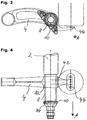
- Fig. 3 shows a further preferred embodiment of a non-inventive suspension system, wherein in particular the support member 10 is clearly shown.
- the carrier element 10 is particularly preferably a brake carrier to which the components of the brake system of a commercial vehicle which are stationary relative to the commercial vehicle are fixed, for example the brake disk or the brake shoes of a drum brake. Furthermore, it is shown in the figure that the receiving portion 44 of the link member 4 is located well below the main axis of the axle stub element 8 and in this way the height of the suspension system can be significantly reduced.
- a spring element mounted on the receiving region 44 is indicated, wherein it is particularly advantageous for a given vertical extension of this spring element to fix the spring element as deep as possible, ie as far down as possible on the link element 4 in the figure.
- Fig. 4 is shown a plan view of a preferred embodiment of the non-inventive suspension system.
- the stub axle element 8 preferably has a first attachment region 82 and a second attachment portion 84 in order to be connected to the link element 4 as well as to the carrier element 10 in a non-positive and cohesive manner.
- the axle tube element 2 is aligned coaxially with the axle stub element 8 and is particularly preferably fixed by means of a friction welding method to the end of the axle stub element 8 shown in the figure above.
- axle tube element 2 at least in regions into the end of the axle stub element 8 shown in the figure above, and in turn provide an adhesive layer 6 and the axle tube element 2 by means of a hydroforming process at least in the area in which it overlaps with the axle stub element 8, widen and thus fix it non-positively to the axle stub element 8.
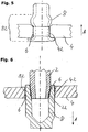
- Fig. 5 is a detailed view of a preferred fixing variant of the axle stub element 8 on the handlebar element 4 is shown.
- a positive connection between the axle stub element 8 and link element 4 is provided.
- This form-fit is particularly preferably achieved in that the stub axle 8 has a first attachment portion 82 which has a greater extent along the axial direction A than the link member 4 in the region of the recess 42.
- the Achsstummelement 8 is widened so that one creates a frictional connection between the region introduced in the recess and, on the other hand, the axle stub element 8 preferably forms an undercut with the recess 42 in front of and / or behind the link element 4. It is in this way advantageously prevents a displacement of the stub axle 8 relative to the link element 4 along the axial direction A.
- the axle stub element 8 can have a curl at one end, which can be shaped, for example, by means of a mandrel.
- Fig. 6 shows a sectional view of another preferred embodiment of a non-inventive suspension system.
- the axle stub element 8 and the Achsrohrelement 2 are preferably coaxially aligned with each other, wherein the mounting portion 22 of the Achsrohrelements 2 in the preferably open end of the Achsstummelelements 8 can be inserted, wherein by means of a preferably conical or conical shape of the first mounting portion 22 is a non-positive connection the stub axle 8 can be produced.
- the non-positive connections between the axle stub element 8 and the link element 4 and Achsrohrelement 2 and Achsstummelement 8 reinforced by each provided on the contact surfaces adhesive layers 6 cohesively.
Landscapes
- Engineering & Computer Science (AREA)
- Mechanical Engineering (AREA)
- Vehicle Body Suspensions (AREA)
- Steering Devices For Bicycles And Motorcycles (AREA)
Description
- Die vorliegende Erfindung betrifft ein Fahrwerksystem für Nutzfahrzeuge gemäß Anspruch 1.
- Fahrwerksysteme der in der Rede stehenden Art sind aus dem Stand der Technik bekannt. So wird zumeist die Fahrzeugachse für ein Nutzfahrzeug über ein oder mehrere Lenkerelemente und Federelemente am Fahrzeugrahmen federnd gelagert, wobei die Verbindung zwischen dem oder den Lenkerelementen und der Fahrzeugachse bevorzugt mittels Schweißverfahren hergestellt ist. Nachteilig bei Schweißverfahren ist es, dass durch den hohen lokalen Temperatureintrag in das Lenkerelement und die Fahrzeugachse Gefügestörungen und Materialspannun-gen auftreten können. Als alternative Lösung ist die kraftschlüssige Verbindung von Fahrzeugachse und Lenkerelement, insbesondere durch Aufweiten der Fahrzeugachse im Bereich des Lenkerelementes, bekannt, wobei jedoch die kraftschlüssige Verbindung oft nicht ausreichend ist, um die hohen Torsions- und Biegemomente, die auf das Lenkerelement und die Fahrzeugachse einwirken, übertragen zu können. Jedes der Dokumente
EP1125775 ,WO 2009/053491 undWO 2008/055958 offenbart ein relenvantes Fahrwezusystem nach der Stand der Technik. - Aufgabe der vorliegenden Erfindung ist es, ein Fahrwerksystem bereitzustellen, welches auf einfache Weise herzustellen ist und den Festigkeitsanforderungen für den Einsatz in Nutzfahrzeugen genügt.
- Diese Aufgabe wird gelöst mit einem Fahrwerksystem gemäß den unabhängigen Ansprüchen 1 und 12 und einem Verfahren zur Herstellung eines Fahrwerksystems für Nutzfahrzeuge gemäß dem unabhängigen Anspruch 13. Weitere Vorteile und Merkmale der Erfindung ergeben sich aus den abhängigen Ansprüchen.
- Erfindungsgemäß umfasst das Fahrwerksystem für Nutzfahrzeuge ein Achsstummelelement und ein Lenkerelement, wobei das Lenkerelement eine Aussparung und das Achsstummelelement einen ersten Befestigungsabschnitt aufweist, wobei der erste Befestigungsabschnitt in der Aussparung des Lenkerelements angeordnet ist und aufgrund eines Umformvorgangs kraftschlüssig an der Aussparung festgelegt ist und wobei zwischen dem ersten Befestigungsabschnitt und der Aussparung eine adhäsive Schicht vorgesehen ist, über die ein Stoffschluss zwischen dem ersten Befestigungsabschnitt des Achsstummelelements und der Aussparung des Lenkerelements gebildet ist. Das Achsstummelement ist bevorzugt zumindest bereichsweise rotationssymmetrisch ausgebildet und dient in erster Linie dazu, weitere Komponenten des Fahrwerksystems drehbar zu lagern. Dazu weist das Achsstummelelement insbesondere bevorzugt Bereiche, bzw. Flächen auf, auf denen Wälzkörper eines Wälzlagers abrollen können, um beispielsweise die drehbare Nabe des Fahrzeugrades eines Nutzfahrzeuges drehbar an dem Fahrwerksystem zu lagern. Das Achsstummelelement weist erfindungsgemäß einen ersten Befestigungsabschnitt auf, über welchen das Achsstummelelement in einer Aussparung des Lenkerelements festlegbar ist. Bevorzugt ist der erste Befestigungsabschnitt des Achsstummelelements, ebenfalls rotationssymmetrisch ausgelegt, beispielsweise als Hohlkörper bzw. rohrförmig, und weist insbesondere bevorzugt eine Außenkontur auf, welche im Wesentlichen mit der Innenkontur der Aussparung des Lenkerelements korrespondiert und in diese eingeführt werden kann. Alternativ bevorzugt ist sowohl die Außenkontur des ersten Befestigungsabschnittes des Achsstummelelements als auch die Innenkontur der Aussparung des Lenkerelements eckig oder quaderförmig ausgebildet, bzw. weist einen rechteckigen Querschnitt auf, wobei bei dieser bevorzugten Ausführungsform das Achsstummelement formschlüssig gegen Verdrehung relativ zum Lenkerelement gesichert ist. Um das Achsstummelement am Lenkerelement festzulegen, ist es bevorzugt, dass der erste Befestigungsabschnitt zumindest bereichsweise derart umgeformt ist, dass eine kraftschlüssige Verbindung zwischen dem ersten Befestigungsabschnitt und der Aussparung des Lenkerelements gebildet ist. Dabei ist es insbesondere bevorzugt, dass der erste Befestigungsabschnitt nach dem Einführen in die Aussparung, beispielsweise mittels eines Innenhochdruck-Umformverfahrens (abgekürzt IHU), derart aufgeweitet wird, dass die Außenkontur des ersten Befestigungsabschnittes gegen die Innenkontur der Aussparung des Lenkerelements presst und das Achsstummelelement auf diese Weise kraftschlüssig mit dem Lenkerelement verbunden ist. Um die kraftschlüssige Verbindung zwischen Achsstummelelement und Lenkerelements zu verstärken, ist erfindungsgemäß eine adhäsive Schicht zwischen dem ersten Befestigungsabschnitt und der Aussparung vorgesehen, um einen Stoffschluss zwischen den beiden gegenüberliegenden Flächen des ersten Befestigungsabschnittes und des Achsstummelelements herzustellen. Mit anderen Worten stellt die adhäsive Schicht eine Klebverbindung zwischen dem Lenkerelement und dem Achsstummelelement her. In besonders vorteilhafter Weise verstärkt die adhäsive Schicht nicht nur die Verbindung zwischen Lenkerelement und Achsstummelelement, sondern verhindert auch das Eindringen von Feuchtigkeit oder Schadstoffen in den Kontaktbereich zwischen Lenkerelement und Achsstummelelement. Auf diese Weise kann insbesondere bevorzugt die Lebensdauer bzw. die Standzeit der kraftschlüssigen bzw. stoffschlüssigen Verbindung von Lenkerelement und Achsstummelelement erhöht werden. Besonders bevorzugt ist das Achsstummelelement einstückig ausgeführt. Auf diese Weise kann die Anzahl zu montierender Teile und damit die Montage des gesamten Fahrwerkssystems reduziert werden. Mit Vorteil wird das Achsstummelelement mit möglichst wenigen Verfahrensschritte, bspw. Gießen und anschließend zerspanend nachbearbeiten, oder Walzen, hergestellt.
- In der enfindungsgemäßen Ausführungsform ist ein Achsrohrelement vorgesehen, das an dem Lenkerelement festgelegt ist, um insbesondere die Stabilität des Fahrwerksystems zu erhöhen. Bevorzugt ist das Achsrohrelement, ein sich länglich längs einer Axialrichtung erstreckendes, rohrförmiges Bauteil, welches insbesondere bevorzugt zwei gegenüberliegende Lenkerelemente miteinander verbindet. Mit anderen Worten ist das Achsrohrelement bevorzugt die starre Achse im Fahrwerk eines Nutzfahrzeuges. Mit Vorteil ist das Achsrohrelement an einem distalen Ende in Axialrichtung am Lenkerelement festgelegt, wobei die Axialrichtung des Achsrohrelementes nicht zwingend koaxial zur Axialrichtung des Achsstummelelementes ausgerichtet sein muss. Bevorzugt ist es, dass das Achsrohrelement derart fest mit dem Lenkerelement verbunden ist, dass es Biegemomente, welche von den Rädern über das Achsstummelelement auf das Lenkerelement übertragen werden, aufnimmt und das Lenkerelement gegen Verdrehung quer zur Axialrichtung sichert. Alternativ bevorzugt kann es sein, dass das Achsrohrelement direkt am Achsstummelelement, bzw. dessen, den bevorzugten Aufnahmebereichen für Wälzlager abgewandten, distalen Ende festgelegt ist, wobei zur Festlegung des Achsrohrelementes am Achsstummelelement ein Reibschweißverfahren vorteilhaft eingesetzt werden kann.
- In bevorzugter Weise ist das Achsrohrelement kraft- und/oder stoffschlüssig an dem Lenkerelement festgelegt. Um bei der Festlegung des Achsrohrelements am Lenkerelement Temperaturspannungen und Gefügeveränderungen sowohl im Lenkerelement als auch im Achsrohrelement zu vermeiden, ist es bevorzugt, das Achsrohrelement mittels einer kraftschlüssigen Verbindung am Lenkerelement festzulegen, welche durch das Aufbringen einer adhäsiven Schicht im Kontaktbereich zwischen beiden Elementen durch eine stoffschlüssige Verbindung unterstützt wird. Dieses bevorzugte Festlegungsverfahren des Achsrohrelementes am Lenkerelement ähnelt dem Verfahren, mit welchem das Achsstummelelement am Lenkerelement festgelegt ist, so dass deren Merkmale hier analog Anwendung finden. Das Lenkerelement weist hierfür bevorzugt eine zweite Aussparung auf, in welche ein erster Befestigungsbereich des Achsrohrelementes einführbar ist, wobei dieser erste Befestigungsbereich durch Aufweiten, beispielsweise mittels IHU, kraftschlüssig an der zweiten Aussparung des Lenkerelements festlegbar ist. Zu beachten ist hierbei lediglich, dass beim Einsatz des IHUs die Bereiche des Achsrohrelementes, welche nicht durch den im Inneren des Achsrohrelementes angelegten, beispielsweise durch ein Fluid erzeugten Druck aufgeweitet werden sollen, mit Hilfe von Formelementen gegen ein Aufblähen zu schützen sind. Die kraftschlüssige Verbindung zwischen Achsrohrelement und Lenkerelement kann insbesondere bevorzugt durch den Einsatz einer adhäsiven Schicht und eine durch diese gebildete stoffschlüssige Verbindung unterstützt werden. Alternativ bevorzugt kann das Achsrohrelement auch durch eine rein stoffschlüssige Verbindung, beispielsweise eine Rotationsreibschweißverbindung oder Schwingungsreibschweißverbindung am Lenkerelement festgelegt sein.
- In besonders bevorzugter Weise ist das Achsstummelelement quer zu einer Haupterstreckungsachse des Achsrohrelements im Bezug auf das Achsrohrelement versetzt angeordnet, um bei bestehender Verbindung zwischen einem der beiden Elemente mit dem Lenkerelement das jeweils andere Element durch einen Umformvorgang kraftschlüssig am Lenkerelement festzulegen. Um das Achsstummelelement bzw. das Achsrohrelement unabhängig voneinander bzw. in aufeinanderfolgender Reihenfolge am Lenkerelement kraftschlüssig festlegen zu können, werden beide Elemente bevorzugt quer zur Axialrichtung bzw. zur Haupterstreckungsachse des Achsrohrelementes versetzt zueinander am Lenkerelement vorgesehen bzw. angeordnet. Besonders bevorzugt ist es, wenn das Achsstummelelement bzw. das Achsrohrelement mit dem jeweiligen ersten Befestigungsabschnitt in die Aussparung des Lenkerelementes eingeführt bzw. durch diese hindurch gesteckt wird und in der der Einsteckrichtung entgegen gerichteten Richtung beispielsweise ein Dorn eingeführt wird, welcher wiederum ein Aufweiten des jeweiligen ersten Befestigungsabschnittes erreicht. Mit Hilfe der bevorzugten versetzten Anordnung des Achsstummelelementes und des Achsrohrelementes am Lenkerelement können also beide Elemente in aufeinanderfolgender Reihenfolge in der erfindungsgemäß vorgesehenen Weise am Lenkerelement festgelegt werden. Insbesondere bevorzugt weisen das Achsrohrelement und das Achsstummelelement in ihren jeweiligen ersten Befestigungsabschnitten die gleichen geometrischen Eigenschaften auf, so dass nur eine Umform-Maschine bzw. nur ein Dorn, der zur Umformung mittels einer Presse in den jeweiligen Befestigungsabschnitt eingeführt wird, sowohl für die Festlegung des Achsstummelelements als auch für die Festlegung des Achsrohrelements am Lenkerelement verwendet werden kann. Es können auf diese Weise insbesondere Maschinen- und Werkzeugkosten eingespart werden.
- Bevorzugt ist ein Trägerelement vorgesehen, welches am Achsrohrelement und/oder am Achsstummelelement und/oder am Lenkerelement festlegbar ist, um zusätzliche Fahrwerkselemente an dem Fahrwerksystem festzulegen. Das Trägerelement kann beispielsweise ein Bremsträger sein, an welchem eine Bremsscheibe, ein Bremszylinder und weitere Systeme der Radaufhängung eines Nutzfahrzeuges festlegbar sind. Bevorzugt kann es sein, dass das Trägerelement zur Aufnahme höherer Momente nicht nur an einem Element, also beispielsweise am Achsrohr- oder Achsstummelelement festgelegt ist, sondern über eine Vielzahl von Kontakt- bzw. Befestigungspunkten sowohl am Achsrohrelement als auch am Achsstummelelement oder am Lenkerelement festlegbar ist. Insbesondere bevorzugt ist das Trägerelement plattenförmig ausgelegt und weist eine Haupterstreckungsrichtung auf, welche im Wesentlichen quer zur Axialrichtung des Achsrohrelementes bzw. des Achsstummelelementes ausgerichtet ist.
- In bevorzugter Weise weist das Trägerelement eine Aussparung auf, in welcher ein zweiter Befestigungsabschnitt des Achsrohrelements oder ein zweiter Befestigungsabschnitt des Achsstummelelements einpressbar ist, wobei zwischen der Aussparung des Trägerelements und dem jeweiligen zweiten Befestigungsabschnitt eine weitere adhäsive Schicht vorgesehen ist, um einen Stoffschluss zwischen dem Trägerelement und einem der Elemente Achsrohrelement oder Achsstummelelement zu bilden. Ähnlich der Festlegung des Achsstummelelementes am Lenkerelement kann es bevorzugt sein, dass das Trägerelement über eine kraftschlüssige und durch eine adhäsive Schicht verstärkte stoffschlüssige Verbindung an einem der Elemente Achsrohrelement oder Achsstummelelement festgelegt ist. Hierfür weisen das Achsrohrelement und/oder das Achsstummelelement einen zweiten Befestigungsabschnitt auf, welcher in einer Aussparung des Trägerelements eingeführt wird und anschließend mittels eines Umform-Verfahrens aufgeweitet wird. Analog zur zwischen Achsstummelelement und Lenkerelement vorgesehenen adhäsiven Schicht kann auch an dem zweiten Befestigungsabschnitt eine adhäsive Schicht aufgebracht sein, welche bei Aufweiten des zweiten Befestigungsabschnittes eine stoffschlüssige Verbindung zur Aussparung des Trägerelementes herstellt und wiederum das Eindringen von korrosionsfördernden Fremdstoffen verhindert. Besonders bevorzugt ist es, dass das Trägerelement am Achsstummelelement vorgesehen ist, wobei insbesondere bevorzugt der zweite Befestigungsabschnitt des Achsstummelelementes in Nähe der Lagerbereiche für das entsprechende Radlager des Achsstummelelementes angeordnet ist. Dies dient insbesondere dazu, die weiteren Systeme des Fahrwerksystems über das Trägerelement nahe dem Rad, welches drehbar am Achsstummelelement angeordnet ist, lagern zu können.
- Insbesondere bevorzugt ist das Lenkerelement an einem ersten distalen Ende schwenkbar an dem Rahmen eines Nutzfahrzeuges festlegbar, wobei das Lenkerelement an einem zweiten, dem ersten Ende gegenüberliegenden, distalen Ende einen Aufnahmebereich aufweist, um ein Federelement zu lagern und Kräfte von dem Federelement an das Achsrohrelement und/oder das Achsstummelelement zu übertragen. Bevorzugt ist das Lenkerelement beispielsweise der Achslenker des Fahrwerksystems eines Nutzfahrzeuges, wobei dieser sich im Wesentlichen parallel zur Fahrzeuglängsrichtung erstreckt. An einem ersten distalen Ende ist das Lenkerelement bevorzugt über ein Lagerauge bzw. eine Lagerbuchse gegen Verlagerung relativ zum Fahrzeugrahmen gesichert und schwenkbar an einem beispielsweise Lagerbock festgelegt, wobei die Drehachse der Schwenkbewegung insbesondere bevorzugt quer zur Fahrzeuglängsrichtung und parallel zur Axialrichtung der Fahrzeugachse bzw. des Achsrohrelements ausgerichtet ist. An seinem, dem ersten Ende gegenüberliegenden, zweiten distalen Ende ist das Lenkerelement bevorzugt über einen Aufnahmebereich an einem Federelement, beispielsweise einer Spiralfeder oder einer Luftfeder, gelagert, wobei dieses Federelement im Wesentlichen dazu dient, die Schwenkbewegung des Lenkerelementes hin zu einer Ruhelage streben zu lassen. Bevorzugt zwischen dem ersten und dem zweiten distalen Ende bzw. zwischen dem ersten distalen Ende und dem Aufnahmebereich für das Federelement ist die Aussparung, welche mit dem Achsstummelelement in Eingriff steht, am Lenkerelement vorgesehen. Auf diese Weise ist es möglich, dass Vertikalbewegungen des Achsstummelelementes in Schwenkbewegung des Lenkerelementes gewandelt werden und die dabei erzeugten Vertikalbewegungen des Aufnahmebereiches des Federelementes am Lenkerelement in einer Verformung des Federelementes resultieren und auf diese Weise vom Federelement gedämpft bzw. in eine Ruhelage zurückgeführt werden. Insbesondere bevorzugt ist es, dass das Lenkerelement möglichst kurz bzw. möglichst kompakt gehalten wird, um sowohl benötigten Bauraum als auch Gewicht einzusparen, wobei in besonders bevorzugter Weise der Aufnahmebereich für das Federelement und die Aussparung, in welcher das Achsstummelelement eingreift, möglichst nah beieinander angeordnet sind. Zu beachten ist hierbei jedoch, dass bei einem sehr kurzen Lenkerelement bei einem Einfederungsvorgang des Federelementes die Schwenkbewegung des Lenkerelementes eine stark kreisförmig ausgebildete Bewegung des Aufnahmebereiches des Lenkerelementes zur Folge hat, wobei die Feder bzw. das Federelement nicht nur in vertikaler Richtung verformt wird, sondern auch in Fahrzeuglängsrichtung eine starke Verformung erfahren kann.
- In insbesondere bevorzugter Weise ist die adhäsive Schicht mittels eines Polyurethans oder eines Epoxydharzes oder eines Silikons gebildet. Besonders bevorzugt ist hierbei die Verwendung eines Epoxydharzes, weil dieses besonders hohe Festigkeitswerte bei der Verbindung eines Metalls mit einem weiteren Metall erreicht.
- In einer bevorzugten Ausführungsform ist das Achsstummelelement und/oder das Achsrohrelement derart umgeformt, dass zumindest eine Hinterschneidung gebildet ist, durch welche ein Formschluss zwischen dem ersten Befestigungsabschnitt und der Aussparung des Lenkerelements hergestellt ist. Bevorzugt kann es sein, dass bei der Umformung des Befestigungsbereichsabschnittes des Achsrohrelements nicht nur ein Kraftschluss mit der Aussparung des Lenkerelements gebildet ist, sondern der erste Befestigungsabschnitt des Achsstummelelements, bzw. des Achsrohrelements sowohl vor als auch hinter der Kontaktfläche mit der Aussparung des Lenkerelementes derart ausgebeult, gebördelt oder aufgeweitet ist, dass der Querschnitt des ersten Befestigungsabschnittes in diesen Bereichen einen größeren Durchmesser, bzw. eine größere Querschnittserstreckung aufweist als die Aussparung des Lenkerelementes. Auf diese Weise ist eine Hinterschneidung gebildet, welche einen Formschluss herstellt, der insbesondere Verlagerungen des Achsstummelements oder des Achsrohrelements längs der Axialrichtung relativ zum Lenkerelement verhindert. Besonders bei der Verwendung eines IHU kann auf diese Weise sehr leicht die Aufweitung des Achsstummelelements oder des Achsrohrelements in den Bereichen kurz vor und kurz nach dem Kontakt zum Lenkerelement derart zugelassen werden, dass ein leichtes Ausbeulen des Achsrohrelementes im ersten Befestigungsabschnitt stattfindet und auf diese Weise das Achsrohrelement formschlüssig am Lenkerelement festgelegt ist.
- Mit Vorteil ist die adhäsive Schicht derart in dem Kontaktbereich der jeweils korrespondierenden Bauteile verteilt, dass ein Eindringen von Feuchtigkeit und Schadstoffen in den Kontaktbereich verhindert ist. Die adhäsive Schicht, welche bevorzugt bei der Festlegung des Achsstummelelements, des Achsrohrelements und des Trägerelements am Lenkerelement eingesetzt wird, soll bevorzugt auch ein Eindringen von Feuchtigkeit und Farbstoffen in den Kontaktbereich der jeweiligen Elemente bzw. Bauteile verhindern. Zu diesem Zweck ist es insbesondere bevorzugt, dass der Ringraum, welcher sich zwischen den jeweiligen ersten Befestigungsabschnitten und den jeweiligen dazu korrespondierenden Aussparungen bildet, an seinen Stirnflächen bevorzugt durch die adhäsive Schicht abgedichtet ist.
- Erfindungsgemäß ist ein Fahrwerksystem für Nutzfahrzeuge vorgesehen, welches ein Achsstummelelement und ein Lenkerelement umfasst, wobei das Lenkerelement eine Aussparung und das Achsstummelelement einen ersten Befestigungsabschnitt aufweist, wobei in einem ersten Zustand der erste Befestigungsabschnitt des Achsstummelelements mit einer adhäsiven Schicht versehen in die Aussparung des Lenkerelements einführbar ist, wobei in einem zweiten Zustand der erste Befestigungsabschnitt derart umgeformt ist, dass ein Kraftschluss zwischen dem ersten Befestigungsabschnitt und der Aussparung vorliegt, wobei im zweiten Zustand mittels einer adhäsiven Schicht ein Stoffschluss zwischen dem ersten Befestigungsabschnitt und der Aussparung gebildet ist. Der erste Zustand ist bevorzugt der Zustand vor dem Verbinden des Achsstummelements am Lenkerelement. Im ersten Zustand weist das Achsstummelelement einen ersten Befestigungsabschnitt auf, der derart geformt ist, dass er in die Aussparung am Lenkerelement einführbar ist.
- Erfindungsgemäß ist ein Verfahren zur Herstellung eines Fahrwerksystems für Nutzfahrzeuge vorgesehen, umfassend die Schritte Bereitstellen eines Achsstummelelementes und eines Lenkerelements, wobei das Achsstummelelement einen ersten Befestigungsabschnitt aufweist und wobei das Lenkerelement eine Aussparung aufweist, in die der erste Befestigungsabschnitt einführbar ist; Aufbringen einer adhäsiven Schicht auf den ersten Befestigungsabschnitt des Achsstummelelements; Einführen des ersten Befestigungsabschnitts in die Aussparung des Lenkerelementes; Umformen, insbesondere Aufweiten, des ersten Befestigungsabschnittes, um einen Kraftschluss zwischen dem ersten Befestigungsabschnitt und der Aussparung und einen Stoffschluss zwischen dem ersten Befestigungsabschnitt der adhäsiven Schicht und der Aussparung des Lenkerelements herzustellen. Das erfindungsgemäße Verfahren zur Herstellung eines Fahrwerksystems zeichnet sich dadurch aus, dass eine kraft- bzw. stoffschlüssige Verbindung zwischen dem Achsstummelelement und dem Lenkerelement hergestellt wird, wobei insbesondere bevorzugt die Nachteile einer rein stoffschlüssigen Verbindung, welche beispielsweise durch ein Schweißverfahren hergestellt wird, vermieden werden. Solche Nachteile können sein, dass während des Schweißvorganges und den dafür benötigten hohen Temperaturen Störungen im Gefüge der jeweiligen Herstellungsmaterialien des Lenkerelements und des Achsstummelelements auftreten können und dass bei Abkühlen nach dem Schweißvorgang erhebliche Thermospannungen in den gefügten Bauteilen die Festigkeit und damit die Betriebssicherheit des Fahrwerksystems erheblich verschlechtern können. Es ist bevorzugt, dass der erste Befestigungsabschnitt des Achsstummelelements derart ausgelegt ist, dass er ohne Weiteres in die Aussparung des Lenkerelements einführbar ist, insbesondere bevorzugt korrespondiert die Außengeometrie des ersten Befestigungsabschnitts zumindest bereichsweise mit der Innengeometrie der Aussparung am Lenkerelement. Nachdem der erfindungsgemäß mit einer adhäsiven Schicht versehene erste Befestigungsabschnitt in die Aussparung des Lenkerelements eingeschoben wurde, ist es bevorzugt, dass das Achsstummelelement in einer gewünschten Lage zum Lenkerelement ausgerichtet wird. Insbesondere bevorzugt ist dies, wenn am Achsstummelelement bereits weitere nicht rotationssymmetrische Teile vorgesehen sind, wie beispielsweise ein Trägerelement, an welchem Bremsen oder ähnliche Sekundärsysteme des Fahrwerksystems festlegbar sind. Nach der bevorzugten genauen Ausrichtung des Achsstummelelementes relativ zum Lenkerelement wird der erste Befestigungsabschnitt des Achsstummelelementes umgeformt, insbesondere bevorzugt aufgeweitet, um einen Kraftschluss zwischen der Außenkontur des Befestigungsabschnittes und der Innenkontur der Aussparung des Lenkerelements herzustellen. Dabei wird während des Umform-Vorganges bevorzugt die Außenfläche des Befestigungsabschnittes gegen die Innenfläche der Aussparung des Lenkerelements verlagert und auf diese aufgepresst, wobei die zwischen den beiden Flächen befindliche adhäsive Schicht möglichst gleichmäßig zwischen den beiden, sich aufeinander zu bewegenden Flächen verteilt, und bei möglichst geringer Spaltdicke zwischen beiden Flächen eine maximale Klebwirkung erreicht. In der Praxis wird es bevorzugt sein, dass die Stellen, an welchen die korrespondierenden Flächen des Achsstummelelementes und des Lenkerelementes aufeinandertreffen, die beiden Elemente kraftschlüssig miteinander verbinden, wobei die durch Oberflächenunebenheiten entstehenden Hohlräume zwischen den ersten Befestigungsabschnitten und den jeweils korrespondierenden Aussparungen des Lenkerelements, die adhäsive Schicht einen Stoffschluss zwischen den jeweiligen korrespondierenden Elementen herstellt.
- In bevorzugter Weise ist ein Achsrohrelement vorgesehen, das mit einem ersten Befestigungsabschnitt in einer Aussparung des Lenkerelements angeordnet und derart umgeformt wird, dass eine kraftschlüssige Verbindung zwischen dem ersten Befestigungsabschnitt des Achsrohrelements und dem Lenkerelement entsteht, wobei über eine adhäsive Schicht ein Stoffschluss zwischen dem ersten Befestigungsabschnitt und dem Lenkerelement hergestellt wird.
- Bevorzugt ist das Lenkerelement ein Gussteil und weist eine Geometrie auf, die insbesondere dafür geeignet ist, einen günstigen Kraftfluss von der Aufnahmestelle des Achsstummelelementes hin zum Aufnahmebereich für das Federelement oder hin zur Aussparung, in welcher das Achsrohrelement eingreift, zu gewährleistet. Insbesondere bevorzugt kann es sein, dass das Lenkerelement aus einer Aluminiumlegierung hergestellt ist. Die erfindungsgemäße Klebverbindung von Achsstummelelement und dem aus Aluminium hergestellten Lenkerelement erweist sich dabei besonders vorteilhaft, da im Allgemeinen bevorzugt ist, für das Achsstummelelement einen Stahl zu verwenden, wobei die bei einer Metall-MetallVerbindung von Stahl mit Aluminium auftretende Kontaktkorrosion und ähnliche intermetallurgische Verschleißvorgänge durch die adhäsive Schicht verhindert werden können. Der Einsatz der adhäsiven Schicht ermöglicht bevorzugt, die beiden Metallflächen voneinander zu trennen, um die sogenannte galvanische Korrosion zu verhindern. Diese Korrosion bzw. dieser Korrosionsvorgang entsteht insbesondere dann, wenn unterschiedliche Metalle miteinander in Kontakt gebracht werden, wobei aufgrund der unterschiedlichen elektrischen Potenziale das jeweils unedlere Metall korrodiert.
- Weitere Vorteile und Merkmale der Erfindung ergerben sich aus der nachfolgenden Beschreibung bevorzugter Ausführungsformen des Fahrwerksystemes mit Bezug auf die beigefügten Figuren. Einzelne Merkmale der verschiedenen Ausführungsformen können dabei im Rahmen der Erfindung miteinander kombiniert werden. Es zeigen:
- Fig. 1
- Eine Seitenansicht einer bevorzugten Ausführungsform des erfindungsgemäßen Fahrwerksystems,
- Fig. 2
- eine Draufsicht der in
Fig. 1 gezeigten bevorzugten Ausführungsform des erfindungsgemäßen Fahrwerksystems, - Fig. 3
- eine Seitenansicht einer weiteren bevorzugten Ausführungsform eines nicht-erfindungsgemäßen Fahrwerksystems,
- Fig. 4
- eine Draufsicht der in
Fig. 3 gezeigten bevorzugten Ausführungsform des nicht-erfindungsgemäßen Fahrwerksystems, - Fig. 5
- eine Ansicht einer bevorzugten Ausführungsform des erfindungsgemäßen Fahrwerkssystems, und
- Fig. 6
- eine Schnittansicht einer bevorzugten Ausführungsform des nicht-erfindungs-gemäßen Fahrwerkssystems.
- In
Fig. 1 ist eine bevorzugte Ausführungsform des erfindungsgemäßen Fahrwerksystems gezeigt, welches die Komponenten Lenkerelement 4, Achsstummelelement 8 und Achsrohrelement 2 umfasst. Das Lenkerelement 4 weist eine Vielzahl von Aussparungen, bevorzugt kreisförmigen Bohrungen auf, die bevorzugt parallel zu einer Axialrichtung A in das Lenkerelement 4 eingebracht sind. Die Axialrichtung A ist dabei die Beobachtungsrichtung des Betrachters der Figur. Das Lenkerelement 4 weist weiterhin eine längliche Form auf, wobei an einem ersten distalen Ende (in der Figur links gezeigt) eine Aussparung vorgesehen ist, mit welcher das Lenkerelement 4 schwenkbar am Fahrzeugrahmen des Nutzfahrzeuges festlegbar ist und wobei an dem - dem ersten distalen Ende gegenüberliegenden - zweiten distalen Ende ein Aufnahmebereich 44 vorgesehen ist, an welchem beispielsweise eine Luftfeder lagerbar ist, welche das zweite distale Ende (in der Figur rechts gezeigt) in vertikaler Richtung gegen Verlagerung relativ zum Fahrzeugrahmen des Nutzfahrzeuges abstützt. Es ist bevorzugt, dass die Aussparung bzw. der Aufnahmebereich am ersten distalen Ende des Lenkerelements 4 kreisförmig ausgelegt ist, insbesondere, um eine Lagerbuchse aufzunehmen und um die Schwenkbarkeit des Lenkerelements 4 um eine parallel zur Axialrichtung A verlaufende Achse zu ermöglichen. Benachbart zum Aufnahmebereich 44 weist das Lenkerelement 4 bevorzugt eine Aussparung 42 auf, in der erfindungsgemäß ein Achsstummelelement 8 festlegbar ist. Das Achsstummelelement 8 ist insbesondere bevorzugt aus einem anderen Material hergestellt als das Lenkerelement 4. In vorteilhafter Weise ist zwischen dem Achsstummelelement 8 und dem Lenkerelement 4 eine adhäsive Schicht 6 angeordnet, die bevorzugt zum einen die intermetallische Korrosion verhindert und zum anderen mittels eines Stoffschlusses mit den jeweiligen Kontaktflächen der beiden Elemente die Festlegung des Achsstummelelements 8 am Lenkerelement 4 verstärkt. Das Achsstummelelement 8 weist bevorzugt kreisförmige, bzw. zylinderförmige Flächen auf, an welchen insbesondere bevorzugt ein Wälzlager eines Radlagers zum Eingriff gebracht werden kann. Dies dient insbesondere dazu, ein Rad eines Nutzfahrzeuges an dem Achsstummelelement 8 drehbar bzw. rotierend zu lagern. Das Lenkerelement 4 weist bevorzugt eine zweite Aussparung auf (in der Figur links neben der Aussparung 42 dargestellt), in welcher ein Achsrohrelement 2 zum Eingriff bringbar ist, wobei wiederum eine adhäsive Schicht 6 zwischen den Kontaktflächen des Lenkerelements 4 und des Achsrohrelements 2 angeordnet ist, die einen Stoffschluss herstellt. Insbesondere bevorzugt ist es, dass sowohl das Achsrohrelement 2 als auch das Achsstummelelement 8 nach dem jeweiligen Einführen in die entsprechende Aussparung am Lenkerelement 4 derart umgeformt werden, dass ein Kraftschluss zwischen dem jeweiligen Element, Achsrohrelement 2 oder Achsstummelelement 8, und dem Lenkerelement 4 entsteht. Insbesondere bevorzugt ist es, die entsprechenden Bereiche des Achsrohrelements 2, bzw. des Achsstummelelements 8 aufzuweiten, um diese gegen die nach innen weisende Wand der Aussparung am Lenkerelement 4 zu pressen. Insbesondere im Vergleich zu einem Reibschweißverfahren, bei dem besonders bevorzugt rotierende Bauteile gegen jeweils an ihnen festzulegende Bauteile gepresst werden, und bei Erreichen einer bestimmten Temperatur eine Anschmelzung des Materials beider Bauteile stattfindet, lassen sich die entsprechenden Bauteile bei dem erfindungsgemäßen Verfahren genauer zueinander positionieren, da kein Rotationsvorgang notwendig ist, um die entsprechende Wärme bzw. die entsprechende verbindende Kraft herzustellen. Um Gewicht einzusparen, ist es insbesondere bevorzugt, dass das Lenkerelement 4 weitere Aussparungen bzw. Materialverdünnungen aufweist, so dass für das Lenkerelement 4 insgesamt eine Geometrie entsteht, die einen günstigen Kraftfluss ermöglicht, und gleichzeitig die Materialparameter, wie beispielsweise die Streckgrenze oder die Bruchfestigkeit des Herstellungsmaterials des Lenkerelements 4 möglichst vollständig ausnutzt, wodurch eine Überdimensionierung bzw. ein zu hohes Gewicht des Lenkerelements 4 vermieden wird. -
Fig. 2 zeigt eine Draufsicht einer bevorzugten Ausführungsform des erfindungsgemäßen Fahrwerksystems, welche größtenteils der inFig. 1 gezeigten bevorzugten Ausführungsform des erfindungsgemäßen Fahrwerksystems gleicht. Ein Unterschied besteht darin, dass an dem Achsstummelelement 8 ein Trägerelement 10 festgelegt ist, um weitere Systeme bzw. Komponenten an dem Fahrwerksystem festzulegen. Bevorzugt ist es, dass das Achsrohrelement 2 und das Achsstummelelement 8 eine jeweils parallel zur Axialrichtung A verlaufende Haupterstreckungsrichtung aufweisen, wobei sie insbesondere bevorzugt im Wesentlichen rotationssymmetrisch um ihre jeweilige Haupterstreckungsrichtung ausgelegt sind. Insbesondere bevorzugt ist es, dass das Achsstummelelement 8 und das Achsrohrelement 2 quer zur Axialrichtung A versetzt zueinander am Lenkerelement 4 festgelegt, um zu ermöglichen, während des Fertigungsvorganges zunächst das Achsrohrelement 2 in die Aussparung am Lenkerelement 4 einzuschieben, den Befestigungsabschnitt 22 aufzuweiten und anschließend das Achsstummelelement 8 von - in der Figur - unten in die Aussparung 42 am Lenkerelement 4 einzuführen, und den Befestigungsabschnitt 82 des Achsstummelelements 8 aufzuweiten und auf diese Weise das Achsstummelelement 8 am Lenkerelement 4 kraftschlüssig festzulegen. Diese Herstellungsreihenfolge wäre nicht möglich, wenn das Achsrohrelement 2 und das Achsstummelelement 8 koaxial zueinander ausgerichtet sind, wobei die jeweilige offene Seite der beiden bevorzugt rohrförmig ausgelegten Elemente, Achsrohrelement 2 und Achsstummelelement 8, durch das jeweils gegenüberliegende Element verdeckt wäre. Insbesondere bevorzugt ist es, dass das Trägerelement 10 bereits vor der Festlegung des Achsstummelelements 8 am Lenkerelement 4 an dem zweiten Befestigungsabschnitt 84 des Achsstummelelements 8 festgelegt ist. Bevorzugt ist an den Befestigungsabschnitten 82 und 84 des Achsstummelelements 8 und dem Befestigungsabschnitt 22 des Achsrohrelements 2 eine adhäsive Schicht 6 vorgesehen, welche die kraftschlüssige Verbindung der jeweiligen Elemente 2 und/oder 8 mit dem Lenkerelement 4, bzw. dem Trägerelement 10 durch einen Stoffschluss unterstützt und verstärkt. Weiterhin ist es durch den Einsatz der adhäsiven Schicht 6 möglich, verschiedene Herstellungsmaterialien für das Achsrohrelement 2, das Achsstummelelement 8, das Lenkerelement 4 und das Trägerelement 10 zu verwenden, ohne eine erhöhte Gefahr einer intermetallischen bzw. galvanischen Korrosion in Kauf nehmen zu müssen. Deutlich dargestellt ist inFig. 2 die kompakte Auslegung des Lenkerelements 4, bei welcher der Aufnahmebereich 44 für eine gestrichelt angedeutete Luftfeder derart ausgelegt ist, dass die Luftfeder von oben her gesehen die Haupterstreckungsachse des Achsstummelelements 8 schneidet. Das Lenkerelement 4 ermöglicht durch die, auf günstigen Kraftfluss, bzw. Spannungsverlauf optimierte Geometrie, die Aufnahme hoher Biegemomente bei gleichzeitig kompakter Bauweise. Die Anordnung der Aufnahme 44 für eine Luftfeder oder ein ähnliches Federelement kann möglichst nah am Achsrohrelement 2 und gleichzeitig am Achsstummelelement 8 erfolgen, wodurch nicht nur die Länge in Fahrzeuglängsrichtung, sondern auch das Gewicht des Lenkerelements 4 reduziert werden kann. Weiterhin kann eine bevorzugt flache Auslegung des Fahrwerks des Nutzfahrzeuges erreicht werden, in dem der Angriffspunkt der Luftfeder an dem Aufnahmebereich 44 in vertikaler Richtung unterhalb der Haupterstreckungsachse des Achsstummelements 8 angeordnet ist. In aus dem Stand der Technik bekannten Auslegungsformen eines Fahrwerksystems wird die Luftfeder bzw. der Aufnahmebereich 44 für eine Luftfeder oft oberhalb des Achsrohrelements 2 bzw. des Achsstummelelements 8 angeordnet, was die Bauhöhe des Fahrwerkes erheblich vergrößert und somit bezogen auf das gesamte Nutzfahrzeug aufgrund der Maximalhöhenbegrenzung von Nutzfahrzeugen in einem reduzierten Stauraum resultiert. Weiterhin wird durch die insgesamt kompakte Bauweise des Lenkerelements 4 Gewicht im Vergleich zu herkömmlichen Lenkerelementen eingespart und es können die Treibstoffkosten gesenkt und die maximal vom Nutzfahrzeug transportierbare Nutzlast erhöht werden. -
Fig. 3 zeigt eine weitere bevorzugte Ausführungsform eines nicht-erfindungsgemäßen Fahrwerksystems, wobei insbesondere das Trägerelement 10 deutlich dargestellt ist. Besonders bevorzugt ist das Trägerelement 10 ein Bremsträger, an welchem die relativ zum Nutzfahrzeug feststehenden Komponenten des Bremssystems eines Nutzfahrzeuges festgelegt sind, beispielsweise die Bremsscheibe oder die Bremsbacken einer Trommelbremse. Weiterhin ist in der Figur gezeigt, dass der Aufnahmebereich 44 des Lenkerelements 4 deutlich unterhalb der Haupterstreckungsachse des Achsstummelelements 8 angeordnet ist und auf diese Weise die Bauhöhe des Fahrwerksystems deutlich reduziert werden kann. Mit der ZweiPunkt-Strichlinie ist ein an dem Aufnahmebereich 44 gelagertes Federelement angedeutet, wobei es bei einer vorgegebenen vertikalen Erstreckung dieses Federelements insbesondere vorteilhaft ist, das Federelement möglichst tief, also in der Figur möglichst weit unten am Lenkerelement 4 festzulegen. - In
Fig. 4 ist eine Draufsicht einer bevorzugten Ausführungsform des nicht-erfindungsgemäßen Fahrwerksystems gezeigt. Dabei weist das Achsstummelelement 8 bevorzugt einen ersten Befestigungsbereich 82 und einen zweiten Befestigungsabschnitt 84 auf, um kraft- und stoffschlüssig mit dem Lenkerelement 4 als auch mit dem Trägerelement 10 verbunden zu werden. Als Alternative zu den bisher beschriebenen bevorzugten Ausführungsformen ist das Achsrohrelement 2 koaxial zum Achsstummelelement 8 ausgerichtet und insbesondere bevorzugt mittels eines Reibschweißverfahrens an dem in der Figur oben gezeigten Ende des Achsstummelelements 8 festgelegt. Es könnte alternativ dazu auch bevorzugt sein, das Achsrohrelement 2 nach Festlegung des Achsstummelelements 8 am Lenkerelement 4 zumindest bereichsweise in das in der Figur oben gezeigte Ende des Achsstummelelements 8 einzuführen und wiederum eine adhäsive Schicht 6 vorzusehen und das Achsrohrelement 2 durch ein Innenhochdruck-Umformverfahren zumindest in dem Bereich, in welchem es mit dem Achsstummelelement 8 überlappt, aufzuweiten und es auf diese Weise kraftschlüssig an dem Achsstummelelement 8 festzulegen. - In
Fig. 5 ist eine Detailansicht einer bevorzugten Festlegungsvariante des Achsstummelelements 8 am Lenkerelement 4 gezeigt. Dabei ist neben der kraftschlüssigen Festlegung, unterstützt durch einen Stoffschluss über der adhäsive Schicht 6, auch ein Formschluss zwischen Achsstummelelement 8 und Lenkerelement 4 vorgesehen. Dieser Formschluss wird insbesondere bevorzugt dadurch erreicht, dass das Achsstummelelement 8 einen ersten Befestigungsabschnitt 82 aufweist, der eine größere Erstreckung längs der Axialrichtung A aufweist als das Lenkerelement 4 im Bereich der Aussparung 42. Im ersten Befestigungsabschnitt 82 ist das Achsstummelement 8 derart aufgeweitet, dass zum einen ein Kraftschluss zwischen dem in der Aussparung eingeführten Bereich entsteht und zum anderen das Achsstummelelement 8 bevorzugt vor und/oder hinter dem Lenkerelement 4 eine Hinterschneidung mit der Aussparung 42 bildet. Es wird auf diese Weise mit Vorteil eine Verlagerung des Achsstummelelements 8 relativ zum Lenkerelement 4 längs der Axialrichtung A verhindert. Bevorzugt kann das Achsstummelelement 8 an einem Ende eine Bördelung aufweise, welche beispielsweise mittels eines Dorns geformt sein kann. -
Fig. 6 zeigt eine Schnittansicht einer weiteren bevorzugten Ausführungsform eines nicht-erfindungsgemäßen Fahrwerkssystems. Das Achsstummelelement 8 und das Achsrohrelement 2 sind bevorzugt koaxial zu einander ausgerichtet, wobei der Befestigungsabschnitt 22 des Achsrohrelements 2 in das bevorzugt offene Ende des Achsstummelelements 8 einführbar ist, wobei mittels einer bevorzugt konischen, bzw. kegeligen Form des ersten Befestigungsabschnittes 22 eine kraftschlüssige Verbindung mit dem Achsstummelelement 8 herstellbar ist. Dabei ist es bevorzugt, dass bei Einführen des ersten Befestigungsabschnitts 22 des Achsrohrelements 2 der erste Befestigungsabschnitt 82 des Achsstummelements 8 aufgeweitet wird und seinerseits eine kraftschlüssige Verbindung mit der Aussparung 42 des Lenkerelements 4 eingeht. In bevorzugter Weise werden die kraftschlüssigen Verbindungen zwischen Achsstummelelement 8 und Lenkerelement 4 und Achsrohrelement 2 und Achsstummelement 8 durch jeweils an den Kontaktflächen vorgesehene adhäsive Schichten 6 stoffschlüssig verstärkt. -
- 2 - Achsrohrelement
- 4 - Lenkerelement
- 6 - adhäsive Schicht
- 8 - Achsstummelelement
- 10 - Trägerelement
- 22 - erster Befestigungsabschnitt des Achsrohrelements
- 42 - Aussparung des Lenkerelements
- 44 - Aufnahmebereich
- 82 - erster Befestigungsabschnitt des Achsstummelelements
- 84 - zweiter Befestigungsabschnitt des Achsstummelelements
- A - Axialrichtung
Claims (14)
- Fahrwerkssystem für Nutzfahrzeuge, umfassend ein Achsstummelelement (8) und ein Lenkerelement (4),
wobei das Lenkerelement (4) eine Aussparung (42) und das Achsstummelelement (8) einen ersten Befestigungsabschnitt (82) aufweist,
wobei der erste Befestigungsabschnitt (82) in der Aussparung (42) des Lenkerelements (4) angeordnet ist und aufgrund eines Umformvorganges kraftschlüssig an der Aussparung (42) festgelegt ist, und
wobei zwischen dem ersten Befestigungsabschnitt (82) und der Aussparung (42) eine adhäsive Schicht (6) vorgesehen ist, über die ein Stoffschluss zwischen dem ersten Befestigungsabschnitt (82) des Achsstummelelements (8) und der Aussparung (42) des Lenkerelements (4) gebildet ist, wobei ein Achsrohrelement (2) vorgesehen ist, das an dem Lenkerelement (4) festgelegt ist, um insbesondere die Stabilität des Fahrwerkssystems zu erhöhen. - Fahrwerkssystem nach Anspruch 1,
wobei das Achsstummelelement (8) einstückig ausgeführt ist. - Fahrwerkssystem nach Anspruch 1 oder 2,
wobei das Achsrohrelement (2) kraft- und/oder stoffschlüssig an dem Lenkerelement (4) festgelegt ist. - Fahrwerkssystem nach einem der vorhergehenden Ansprüche,
wobei das Achsstummelelement (8) quer zu einer Haupterstreckungsachse des Achsrohrelements (2) in Bezug auf das Achsrohrelement (2) versetzt angeordnet ist, um bei bestehender Verbindung zwischen einem der beiden Elemente (2 oder 8) mit dem Lenkerelement (4), das jeweils andere durch einen Umformvorgang kraftschlüssig an dem Lenkerelement (4) festzulegen. - Fahrwerkssystem nach einem der vorhergehenden Ansprüche,
wobei ein Trägerelement (10) vorgesehen ist, welches am Achsrohrelement (2) und/oder am Achsstummelelement (8) und/oder am Lenkerelement (4) festlegbar ist, um zusätzliche Fahrwerkselemente an dem Fahrwerkssystem festzulegen. - Fahrwerkssystem nach Anspruch 5,
wobei das Trägerelement (10) eine Aussparung aufweist, in welcher ein zweiter Befestigungsabschnitt des Achsrohrelements (2) oder ein zweiter Befestigungsabschnitt (84) des Achsstummelelements (8) einpressbar ist, wobei zwischen der Aussparung des Trägerelements (10) und dem jeweiligen zweiten Befestigungsabschnitt (84) eine weitere adhäsive Schicht (6) vorgesehen ist, um einen Stoffschluss zwischen dem Trägerelement (10) und einem der Elemente Achsrohrelement (2) oder Achsstummelelement (8) zu bilden. - Fahrwerkssystem nach einem der vorhergehenden Ansprüche,
wobei das Lenkerelement (4) an einem ersten distalen Ende schwenkbar an dem Rahmen eines Nutzfahrzeuges festlegbar ist, und
wobei das Lenkerelement (4) an einem zweiten, dem ersten Ende gegenüber liegenden, distalen Ende einen Aufnahmebereich (44) aufweist, um ein Federelement zu lagern und Kräfte von dem Federelement an das Achsrohrelement (2) und/oder das Achsstummelelement (8) zu übertragen. - Fahrwerkssystem nach einem der vorhergehenden Ansprüche,
wobei die adhäsive Schicht (6) mittels eines Polyurethans oder eines Epoxydharzes oder eines Silikons gebildet ist. - Fahrwerkssystem nach einem der vorhergehenden Ansprüche,
wobei das Achsstummelelement (8) und/oder das Achsrohrelement (2) derart umgeformt ist, dass zumindest eine Hinterschneidung gebildet ist, durch welche ein Formschluss zwischen dem ersten Befestigungsabschnitt (82, 22) und der Aussparung (42) des Lenkerelements (4) hergestellt ist. - Fahrwerkssystem nach einem der vorhergehenden Ansprüche,
wobei die adhäsive Schicht (6) derart in dem Kontaktbereich den jeweils korrespondierenden Bauteilen verteilt ist, dass ein Eindringen von Feuchtigkeit und Schadstoffen in den Kontaktbereich verhindert ist. - Fahrwerkssystem nach einem der vorhergehenden Ansprüche,
wobei das Lenkerelement (4) ein Gussteil ist, und
wobei das Lenkerelement (4) eine Geometrie aufweist, die dafür geeignet ist, einen günstigen Kraftfluss vom Achsstummelement (8) hin zu einem Aufnahmebereich (44) für ein Federelement oder hin zur Aussparung (42) zu gewährleisten. - Fahrwerkssystem für Nutzfahrzeuge umfassend ein Achsstummelelement (8) und ein Lenkerelement (4),
wobei das Lenkerelement (4) eine Aussparung (42) und das Achsstummelelement (8) einen ersten Befestigungsabschnitt (82) aufweist,
wobei in einem ersten Zustand der erste Befestigungsabschnitt (82) des Achsstummelelements (8) mit einer adhäsiven Schicht (6) versehen in die Aussparung (42) des Lenkerelements (4) einführbar ist,
wobei in einem zweiten Zustand der erste Befestigungsabschnitt (82) derart umgeformt ist, dass ein Kraftschluss zwischen dem ersten Befestigungsabschnitt (82) und der Aussparung (42) vorliegt,
wobei im zweiten Zustand mittels der adhäsiven Schicht (6) ein Stoffschluss zwischen dem ersten Befestigungsabschnitt (82) und der Aussparung (42) gebildet ist,
wobei ein Achsrohrelement (2) vorgesehen ist, das an dem Lenkerelement (4) festgelegt ist, um insbesondere die Stabilität des Fahrwerkssystems zu erhöhen. - Verfahren zur Herstellung eines Fahrwerkssystems für Nutzfahrzeuge, umfassend die Schritte:a) Bereitstellen eines Achsstummelelements (8) und eines Lenkerelements (4),
wobei das Achsstummelelement (8) einen ersten Befestigungsabschnitt (82) aufweist, und
wobei das Lenkerelement (4) eine Aussparung (42) aufweist, in die der erste Befestigungsabschnitt (82) einführbar ist,b) Aufbringen einer adhäsiven Schicht (6) auf den ersten Befestigungsabschnitt (82) des Achsstummelelements (8),c) Einführen des ersten Befestigungsabschnitts (82) in die Aussparung (42) des Lenkerelements (4),d) Umformen, insbesondere Aufweiten, des ersten Befestigungsabschnitts (82), um einen Kraftschluss zwischen dem ersten Befestigungsabschnitt (82) und der Aussparung (42) und einen Stoffschluss zwischen dem ersten Befestigungsabschnitt (82), der adhäsiven Schicht (6) und der Aussparung (42) des Lenkerelements (4) herzustellen, unde) Festlegen eines Achsrohrelements (2) über einen ersten Befestigungsabschnitt (22) in einer Aussparung des Lenkerelements (4). - Verfahren nach Anspruch 13,
wobei das Achsrohrelement (2) über seinem ersten Befestigungsabschnitt (22) in der Aussparung des Lenkerelements (4) angeordnet und derart umgeformt wird, dass eine kraftschlüssige Verbindung zwischen dem ersten Befestigungsabschnitt (22) des Achsrohrelements (2) und dem Lenkerelement (4) entsteht,
wobei über eine adhäsive Schicht (6) ein Stoffschluss zwischen dem ersten Befestigungsabschnitt (82) und dem Lenkerelement (4) hergestellt wird.
Applications Claiming Priority (2)
| Application Number | Priority Date | Filing Date | Title |
|---|---|---|---|
| DE102011086481.4A DE102011086481B4 (de) | 2011-11-16 | 2011-11-16 | Fahrwerksystem für Nutzfahrzeuge |
| PCT/EP2012/071533 WO2013072192A1 (de) | 2011-11-16 | 2012-10-31 | Fahrwerksystem für nutzfahrzeuge |
Publications (2)
| Publication Number | Publication Date |
|---|---|
| EP2736733A1 EP2736733A1 (de) | 2014-06-04 |
| EP2736733B1 true EP2736733B1 (de) | 2016-03-02 |
Family
ID=47137705
Family Applications (1)
| Application Number | Title | Priority Date | Filing Date |
|---|---|---|---|
| EP12781084.4A Not-in-force EP2736733B1 (de) | 2011-11-16 | 2012-10-31 | Fahrwerksystem für nutzfahrzeuge |
Country Status (4)
| Country | Link |
|---|---|
| US (1) | US9174506B2 (de) |
| EP (1) | EP2736733B1 (de) |
| DE (1) | DE102011086481B4 (de) |
| WO (1) | WO2013072192A1 (de) |
Families Citing this family (17)
| Publication number | Priority date | Publication date | Assignee | Title |
|---|---|---|---|---|
| DE102011086480B4 (de) * | 2011-11-16 | 2021-01-28 | Saf-Holland Gmbh | Achseinheit für Nutzfahrzeuge |
| DE102014216408A1 (de) * | 2014-08-19 | 2016-02-25 | Volkswagen Aktiengesellschaft | System und Verfahren zur reversiblen Befestigung eines Achszapfens an einer Lenkerachse |
| DE102014218325B4 (de) | 2014-09-12 | 2021-10-28 | Saf-Holland Gmbh | Achseinheit |
| DE102014218331B4 (de) | 2014-09-12 | 2018-11-08 | Saf-Holland Gmbh | Achseinheit |
| DE102014223869A1 (de) * | 2014-11-24 | 2016-05-25 | Zf Friedrichshafen Ag | Achsbrücke und Verfahren zur Herstellung einer Achsbrücke |
| DE102014117207A1 (de) * | 2014-11-25 | 2016-05-25 | Saf-Holland Gmbh | Achslenker |
| USD771540S1 (en) * | 2015-06-15 | 2016-11-15 | Saf-Holland, Inc. | Brake spider |
| USD808872S1 (en) * | 2015-09-11 | 2018-01-30 | Eaton S.R.L. | Rocker arm for engine brake |
| USD801895S1 (en) * | 2015-09-22 | 2017-11-07 | Saf-Holland, Inc. | Brake torque plate |
| DE102016102133A1 (de) * | 2016-02-08 | 2017-08-10 | Saf-Holland Gmbh | Achseinheit |
| DE102016107141A1 (de) * | 2016-04-18 | 2017-10-19 | Benteler Steel/Tube Gmbh | Kraftfahrzeuganhänger, Fahrwerkachse, insbesondere für einen Kraftfahrzeuganhänger und Verwendung der Fahrwerksachse und eines Werkstoffes |
| DE102017104554B4 (de) * | 2017-03-06 | 2026-07-09 | Saf-Holland Gmbh | Stummelelement und Achssystem |
| EP3858648B1 (de) * | 2020-01-30 | 2024-11-13 | Stellantis Europe S.p.A. | Hintere federung des kraftfahrzeugs mit einer modularen struktur, die als verbundlenkerachse oder als starrachse konfiguriert werden kann |
| DE102020103762B4 (de) * | 2020-02-13 | 2023-10-12 | Saf-Holland Gmbh | Lenkersystem |
| US12077015B2 (en) | 2020-08-19 | 2024-09-03 | Tribology Innovations, Llc | Torsion axle assembly |
| DE102022201246A1 (de) | 2022-02-07 | 2023-08-10 | Volkswagen Aktiengesellschaft | Verfahren zur Herstellung eines Hilfsrahmens für ein Fahrzeug und Hilfsrahmen |
| CN117341388B (zh) * | 2023-10-09 | 2026-06-12 | 湖南三一中阳机械有限公司 | 轮边密封锁紧组件、车桥总成及作业机械 |
Family Cites Families (47)
| Publication number | Priority date | Publication date | Assignee | Title |
|---|---|---|---|---|
| US2738185A (en) * | 1952-04-15 | 1956-03-13 | American Steel Foundries | Spring and axle assembly |
| FR82194E (fr) | 1958-03-10 | 1964-01-04 | Renault | Dispositif d'entraînement et de suspension de roue motrice dans les véhicules automobiles |
| US3207497A (en) * | 1963-07-02 | 1965-09-21 | Dura Corp | Torsion spring assembly |
| USRE28259E (en) * | 1967-03-13 | 1974-12-03 | Bearihg assembly for elastic joimts | |
| GB1165976A (en) * | 1967-04-22 | 1969-10-01 | Mechanical Services Trailer En | Improvements in or relating to Road-Vehicle Suspension Systems |
| FR1591438A (de) * | 1968-11-13 | 1970-04-27 | ||
| US3701564A (en) * | 1970-07-28 | 1972-10-31 | Willow Hill Ind Inc | Vehicle axle spindle |
| US3783639A (en) * | 1972-06-21 | 1974-01-08 | Ingersoll Mach & Tool Co | Resilient joint |
| US3844583A (en) * | 1973-02-21 | 1974-10-29 | T Sakow | Vehicle torsion bar |
| US4429900A (en) * | 1980-11-06 | 1984-02-07 | Feher Joseph S | Automotive suspension system for maintaining the rear wheels substantially parallel to one another throughout use |
| GB8521143D0 (en) * | 1985-08-23 | 1985-10-02 | Gkn Technology Ltd | Vehicle suspension |
| WO1991012148A1 (en) * | 1990-02-12 | 1991-08-22 | Wharton, Charles, E. | Torsional suspension unit |
| US5163701A (en) * | 1991-09-09 | 1992-11-17 | Csn Manufacturing, Inc. | Torsion spring vehicle suspension |
| US5326128A (en) * | 1991-09-09 | 1994-07-05 | Csn Manufacturing, Inc. | Variable-width torsion spring axle |
| US5277450A (en) * | 1992-07-07 | 1994-01-11 | Henschen Curtiss W | Multiple stage torsion axle |
| DE4441971A1 (de) | 1994-11-25 | 1996-05-30 | Vaw Ver Aluminium Werke Ag | Kraftfahrzeug-Hinterachse und Verfahren zu ihrer Herstellung |
| US5785332A (en) * | 1996-08-01 | 1998-07-28 | Dana Corporation | Motor vehicle steering knuckle assembly |
| US5899470A (en) * | 1997-07-01 | 1999-05-04 | Mor/Ryde International, Inc. | Rubber spring modular wheel suspension for vehicles |
| US6039336A (en) * | 1997-09-19 | 2000-03-21 | Otto Sauer Achsenfabrik Keilberg | Vehicle axle suspension assembly |
| FR2778605A1 (fr) * | 1998-05-13 | 1999-11-19 | Michelin & Cie | Essieu de vehicule equipe d'elements de suspension agissant en torsion |
| US6086162A (en) * | 1998-12-14 | 2000-07-11 | General Motors Corporation | Motor vehicle rear axle and method |
| US6299259B1 (en) * | 1999-07-02 | 2001-10-09 | Charles J. Mackarvich | Removable spindle axle for torsion axle assembly |
| US6340165B1 (en) * | 1999-08-20 | 2002-01-22 | Gary L. Kelderman | Torsion axle and air bag vehicle suspension system |
| FR2805316B1 (fr) | 2000-02-17 | 2003-01-24 | Gen Trailers France | Procede de fixation d'un bras de suspension sur un essieu et essieu pourvu de bras de suspension fixes selon ce procede |
| US7077411B2 (en) * | 2000-11-27 | 2006-07-18 | The Holland Group, Inc. | Vehicle suspension system |
| FR2821020B1 (fr) | 2001-02-21 | 2005-09-16 | Max Sardou | Essieu pour vehicule et application aux essieux multiples |
| US6447073B1 (en) * | 2001-05-02 | 2002-09-10 | Bernhardt P. Goettker | Torsion axle having a selectively replaceable insert assembly |
| US6565159B1 (en) | 2001-10-25 | 2003-05-20 | Hayes Lemmerz International, Inc. | Aluminum wheel carrier and spindle assembly |
| DE20119641U1 (de) | 2001-12-04 | 2002-02-28 | Otto Sauer Achsenfabrik Keilberg, 63856 Bessenbach | Radlagerung an einem Achskörper für Fahrzeuge |
| US20060022424A1 (en) * | 2004-07-30 | 2006-02-02 | Norm Reynolds | Torsion spring cartridge |
| US7347435B2 (en) * | 2005-01-14 | 2008-03-25 | Watson & Chalin Manufacturing, Inc. | Suspension system having reduced weight arm construction |
| US7497450B2 (en) * | 2005-03-29 | 2009-03-03 | Saf-Holland, Inc. | Shrink fit suspension arrangement |
| FR2888559B1 (fr) | 2005-07-15 | 2008-09-26 | Renault Sas | Procede d'assemblage d'un essieu de vehicule automobile du type pourvu de bras de suspension et d'une traverse montee entre lesdits bras, et essieu correspondant |
| DE102005038274C5 (de) | 2005-08-12 | 2018-01-11 | Saf-Holland Gmbh | Radaufhängungslenker |
| CA2526736A1 (fr) * | 2005-11-20 | 2007-05-20 | Systeme Nenuphar Inc | Suspension a torsion |
| DE102006017421B4 (de) * | 2006-02-07 | 2014-02-06 | Daimler Ag | Fahrzeugstarrachse mit in den Achskörper eingelegten und fixierten Anbindungselementen |
| FR2908347B1 (fr) | 2006-11-09 | 2009-11-06 | Renault Sas | Assemblage d'un essieu arriere de vehicule. |
| CA2686516C (en) * | 2007-04-06 | 2014-10-28 | Magna International Inc. | Stress reducing inner sleeve for twist beam and associated method |
| DE102007051501A1 (de) * | 2007-10-27 | 2009-05-07 | Schmitz Cargobull Ag | Achsaggregat mit Achsprofilelement und Achslenkerkörper und Verfahren zur Herstellung eines Achsaggregates |
| US7726674B2 (en) * | 2008-05-08 | 2010-06-01 | Air Suspensions, Inc. | Suspension assembly |
| US7967087B2 (en) * | 2008-06-27 | 2011-06-28 | Caterpillar Sarl | Suspension for a machine |
| DE102009037905A1 (de) * | 2009-08-19 | 2011-02-24 | Benteler Automobiltechnik Gmbh | Kraftfahrzeug-Achskomponente und Verfahren zur Herstellung einer Kraftfahrzeug-Achskomponente |
| US8322737B2 (en) * | 2009-10-21 | 2012-12-04 | Watson & Chalin Manufacturing, Inc. | Suspension system with integrated brake mounting and suspension arm |
| US7954833B1 (en) * | 2010-05-21 | 2011-06-07 | Saf-Holland, Inc. | Trailing beam assembly |
| WO2011147411A2 (de) * | 2010-05-27 | 2011-12-01 | Ksm Castings Gmbh | Achsmodul, insbesondere verbundlenkerachse |
| DE102011086480B4 (de) * | 2011-11-16 | 2021-01-28 | Saf-Holland Gmbh | Achseinheit für Nutzfahrzeuge |
| US8777241B1 (en) * | 2013-03-08 | 2014-07-15 | Ford Global Technologies, Llc | Suspension component with tapered spindle joint |
-
2011
- 2011-11-16 DE DE102011086481.4A patent/DE102011086481B4/de not_active Expired - Fee Related
-
2012
- 2012-10-31 US US14/352,218 patent/US9174506B2/en not_active Expired - Fee Related
- 2012-10-31 EP EP12781084.4A patent/EP2736733B1/de not_active Not-in-force
- 2012-10-31 WO PCT/EP2012/071533 patent/WO2013072192A1/de not_active Ceased
Also Published As
| Publication number | Publication date |
|---|---|
| WO2013072192A1 (de) | 2013-05-23 |
| US20140252740A1 (en) | 2014-09-11 |
| DE102011086481A1 (de) | 2013-05-16 |
| US9174506B2 (en) | 2015-11-03 |
| DE102011086481B4 (de) | 2020-06-10 |
| EP2736733A1 (de) | 2014-06-04 |
Similar Documents
| Publication | Publication Date | Title |
|---|---|---|
| DE102011086481B4 (de) | Fahrwerksystem für Nutzfahrzeuge | |
| EP2576248B1 (de) | Achsmodul, insbesondere verbundlenkerachse | |
| EP2729347B1 (de) | Achsträger mit integrierter träger für einen antrieb | |
| EP2709858B1 (de) | Träger als fahrwerkkomponente | |
| EP3009323B1 (de) | Fahrwerksrahmen eines schienenfahrzeugs | |
| EP1036680B1 (de) | Verbundlenkerachse für Kraftfahrzeuge | |
| EP2599650B1 (de) | Kraftfahrzeug-Fahrwerkskomponente | |
| DE102008038276A1 (de) | Verfahren zur Verbindung von Fahrwerksteilen und Fahrwerksbaugruppe | |
| WO2008119341A1 (de) | Verbindungsstück zum gelenkigen verbinden von im fahrwerk eines fahrzeugs angeordneten bauelementen | |
| DE102012016268A1 (de) | Verbindungsanordnung sowie Querträger mit einer solchen Verbindungsanordnung. | |
| DE102009039479A1 (de) | Stabilisatoranordnung | |
| EP2888153B1 (de) | Lageranordnung und achsträger für ein kraftfahrzeug | |
| EP3191314A1 (de) | Achseinheit | |
| DE102015100261B4 (de) | Träger für ein Kraftfahrzeug und Herstellungsverfahren für einen Träger für ein Kraftfahrzeug | |
| DE102012009458B4 (de) | Lager zum elastischen Koppeln zweier Bauteile | |
| EP3191322B1 (de) | Achseinheit | |
| EP3314141B1 (de) | Bremstrommel | |
| DE102010008179A1 (de) | Stoßdämpfergehäuse | |
| DE102010028400A1 (de) | Querlenker in Schalenbauweise | |
| WO2017080794A1 (de) | Radlagervorrichtung, sowie verfahren zur montage einer radlagervorrichtung | |
| EP3988352A1 (de) | Verbundlenker für ein fahrwerk eines kraftfahrzeugs | |
| EP3142869B1 (de) | Lenkereinheit und verfahren zur herstellung einer lenkereinheit | |
| DE102014106470B4 (de) | Lagerbuchse für ein Fahrwerks- oder Getriebebauteil eines Kraftfahrzeuges | |
| DE102019105712A1 (de) | Verbindungskomponente in der Karosserie oder im Fahrwerksbereich eines Kraftfahrzeugs | |
| EP3592572B1 (de) | Stummelelement und achssystem |
Legal Events
| Date | Code | Title | Description |
|---|---|---|---|
| PUAI | Public reference made under article 153(3) epc to a published international application that has entered the european phase |
Free format text: ORIGINAL CODE: 0009012 |
|
| 17P | Request for examination filed |
Effective date: 20140225 |
|
| AK | Designated contracting states |
Kind code of ref document: A1 Designated state(s): AL AT BE BG CH CY CZ DE DK EE ES FI FR GB GR HR HU IE IS IT LI LT LU LV MC MK MT NL NO PL PT RO RS SE SI SK SM TR |
|
| DAX | Request for extension of the european patent (deleted) | ||
| GRAP | Despatch of communication of intention to grant a patent |
Free format text: ORIGINAL CODE: EPIDOSNIGR1 |
|
| INTG | Intention to grant announced |
Effective date: 20150515 |
|
| GRAP | Despatch of communication of intention to grant a patent |
Free format text: ORIGINAL CODE: EPIDOSNIGR1 |
|
| INTG | Intention to grant announced |
Effective date: 20151007 |
|
| GRAS | Grant fee paid |
Free format text: ORIGINAL CODE: EPIDOSNIGR3 |
|
| GRAA | (expected) grant |
Free format text: ORIGINAL CODE: 0009210 |
|
| AK | Designated contracting states |
Kind code of ref document: B1 Designated state(s): AL AT BE BG CH CY CZ DE DK EE ES FI FR GB GR HR HU IE IS IT LI LT LU LV MC MK MT NL NO PL PT RO RS SE SI SK SM TR |
|
| REG | Reference to a national code |
Ref country code: GB Ref legal event code: FG4D Free format text: NOT ENGLISH |
|
| REG | Reference to a national code |
Ref country code: AT Ref legal event code: REF Ref document number: 777747 Country of ref document: AT Kind code of ref document: T Effective date: 20160315 Ref country code: CH Ref legal event code: EP |
|
| REG | Reference to a national code |
Ref country code: IE Ref legal event code: FG4D Free format text: LANGUAGE OF EP DOCUMENT: GERMAN |
|
| REG | Reference to a national code |
Ref country code: DE Ref legal event code: R096 Ref document number: 502012006176 Country of ref document: DE |
|
| REG | Reference to a national code |
Ref country code: NL Ref legal event code: MP Effective date: 20160302 |
|
| REG | Reference to a national code |
Ref country code: LT Ref legal event code: MG4D |
|
| PG25 | Lapsed in a contracting state [announced via postgrant information from national office to epo] |
Ref country code: HR Free format text: LAPSE BECAUSE OF FAILURE TO SUBMIT A TRANSLATION OF THE DESCRIPTION OR TO PAY THE FEE WITHIN THE PRESCRIBED TIME-LIMIT Effective date: 20160302 Ref country code: NO Free format text: LAPSE BECAUSE OF FAILURE TO SUBMIT A TRANSLATION OF THE DESCRIPTION OR TO PAY THE FEE WITHIN THE PRESCRIBED TIME-LIMIT Effective date: 20160602 Ref country code: ES Free format text: LAPSE BECAUSE OF FAILURE TO SUBMIT A TRANSLATION OF THE DESCRIPTION OR TO PAY THE FEE WITHIN THE PRESCRIBED TIME-LIMIT Effective date: 20160302 Ref country code: FI Free format text: LAPSE BECAUSE OF FAILURE TO SUBMIT A TRANSLATION OF THE DESCRIPTION OR TO PAY THE FEE WITHIN THE PRESCRIBED TIME-LIMIT Effective date: 20160302 Ref country code: GR Free format text: LAPSE BECAUSE OF FAILURE TO SUBMIT A TRANSLATION OF THE DESCRIPTION OR TO PAY THE FEE WITHIN THE PRESCRIBED TIME-LIMIT Effective date: 20160603 |
|
| PG25 | Lapsed in a contracting state [announced via postgrant information from national office to epo] |
Ref country code: LT Free format text: LAPSE BECAUSE OF FAILURE TO SUBMIT A TRANSLATION OF THE DESCRIPTION OR TO PAY THE FEE WITHIN THE PRESCRIBED TIME-LIMIT Effective date: 20160302 Ref country code: SE Free format text: LAPSE BECAUSE OF FAILURE TO SUBMIT A TRANSLATION OF THE DESCRIPTION OR TO PAY THE FEE WITHIN THE PRESCRIBED TIME-LIMIT Effective date: 20160302 Ref country code: RS Free format text: LAPSE BECAUSE OF FAILURE TO SUBMIT A TRANSLATION OF THE DESCRIPTION OR TO PAY THE FEE WITHIN THE PRESCRIBED TIME-LIMIT Effective date: 20160302 Ref country code: LV Free format text: LAPSE BECAUSE OF FAILURE TO SUBMIT A TRANSLATION OF THE DESCRIPTION OR TO PAY THE FEE WITHIN THE PRESCRIBED TIME-LIMIT Effective date: 20160302 Ref country code: NL Free format text: LAPSE BECAUSE OF FAILURE TO SUBMIT A TRANSLATION OF THE DESCRIPTION OR TO PAY THE FEE WITHIN THE PRESCRIBED TIME-LIMIT Effective date: 20160302 Ref country code: PL Free format text: LAPSE BECAUSE OF FAILURE TO SUBMIT A TRANSLATION OF THE DESCRIPTION OR TO PAY THE FEE WITHIN THE PRESCRIBED TIME-LIMIT Effective date: 20160302 |
|
| REG | Reference to a national code |
Ref country code: FR Ref legal event code: PLFP Year of fee payment: 5 |
|
| PG25 | Lapsed in a contracting state [announced via postgrant information from national office to epo] |
Ref country code: IS Free format text: LAPSE BECAUSE OF FAILURE TO SUBMIT A TRANSLATION OF THE DESCRIPTION OR TO PAY THE FEE WITHIN THE PRESCRIBED TIME-LIMIT Effective date: 20160702 Ref country code: EE Free format text: LAPSE BECAUSE OF FAILURE TO SUBMIT A TRANSLATION OF THE DESCRIPTION OR TO PAY THE FEE WITHIN THE PRESCRIBED TIME-LIMIT Effective date: 20160302 |
|
| PG25 | Lapsed in a contracting state [announced via postgrant information from national office to epo] |
Ref country code: RO Free format text: LAPSE BECAUSE OF FAILURE TO SUBMIT A TRANSLATION OF THE DESCRIPTION OR TO PAY THE FEE WITHIN THE PRESCRIBED TIME-LIMIT Effective date: 20160302 Ref country code: PT Free format text: LAPSE BECAUSE OF FAILURE TO SUBMIT A TRANSLATION OF THE DESCRIPTION OR TO PAY THE FEE WITHIN THE PRESCRIBED TIME-LIMIT Effective date: 20160704 Ref country code: SM Free format text: LAPSE BECAUSE OF FAILURE TO SUBMIT A TRANSLATION OF THE DESCRIPTION OR TO PAY THE FEE WITHIN THE PRESCRIBED TIME-LIMIT Effective date: 20160302 Ref country code: SK Free format text: LAPSE BECAUSE OF FAILURE TO SUBMIT A TRANSLATION OF THE DESCRIPTION OR TO PAY THE FEE WITHIN THE PRESCRIBED TIME-LIMIT Effective date: 20160302 Ref country code: CZ Free format text: LAPSE BECAUSE OF FAILURE TO SUBMIT A TRANSLATION OF THE DESCRIPTION OR TO PAY THE FEE WITHIN THE PRESCRIBED TIME-LIMIT Effective date: 20160302 |
|
| REG | Reference to a national code |
Ref country code: DE Ref legal event code: R097 Ref document number: 502012006176 Country of ref document: DE |
|
| PG25 | Lapsed in a contracting state [announced via postgrant information from national office to epo] |
Ref country code: IT Free format text: LAPSE BECAUSE OF FAILURE TO SUBMIT A TRANSLATION OF THE DESCRIPTION OR TO PAY THE FEE WITHIN THE PRESCRIBED TIME-LIMIT Effective date: 20160302 |
|
| PLBE | No opposition filed within time limit |
Free format text: ORIGINAL CODE: 0009261 |
|
| STAA | Information on the status of an ep patent application or granted ep patent |
Free format text: STATUS: NO OPPOSITION FILED WITHIN TIME LIMIT |
|
| PG25 | Lapsed in a contracting state [announced via postgrant information from national office to epo] |
Ref country code: DK Free format text: LAPSE BECAUSE OF FAILURE TO SUBMIT A TRANSLATION OF THE DESCRIPTION OR TO PAY THE FEE WITHIN THE PRESCRIBED TIME-LIMIT Effective date: 20160302 |
|
| 26N | No opposition filed |
Effective date: 20161205 |
|
| PG25 | Lapsed in a contracting state [announced via postgrant information from national office to epo] |
Ref country code: BE Free format text: LAPSE BECAUSE OF NON-PAYMENT OF DUE FEES Effective date: 20161031 Ref country code: SI Free format text: LAPSE BECAUSE OF FAILURE TO SUBMIT A TRANSLATION OF THE DESCRIPTION OR TO PAY THE FEE WITHIN THE PRESCRIBED TIME-LIMIT Effective date: 20160302 Ref country code: BG Free format text: LAPSE BECAUSE OF FAILURE TO SUBMIT A TRANSLATION OF THE DESCRIPTION OR TO PAY THE FEE WITHIN THE PRESCRIBED TIME-LIMIT Effective date: 20160602 |
|
| REG | Reference to a national code |
Ref country code: CH Ref legal event code: PL |
|
| REG | Reference to a national code |
Ref country code: IE Ref legal event code: MM4A |
|
| PG25 | Lapsed in a contracting state [announced via postgrant information from national office to epo] |
Ref country code: LI Free format text: LAPSE BECAUSE OF NON-PAYMENT OF DUE FEES Effective date: 20161031 Ref country code: CH Free format text: LAPSE BECAUSE OF NON-PAYMENT OF DUE FEES Effective date: 20161031 |
|
| PG25 | Lapsed in a contracting state [announced via postgrant information from national office to epo] |
Ref country code: LU Free format text: LAPSE BECAUSE OF NON-PAYMENT OF DUE FEES Effective date: 20161031 |
|
| REG | Reference to a national code |
Ref country code: FR Ref legal event code: PLFP Year of fee payment: 6 |
|
| PG25 | Lapsed in a contracting state [announced via postgrant information from national office to epo] |
Ref country code: IE Free format text: LAPSE BECAUSE OF NON-PAYMENT OF DUE FEES Effective date: 20161031 |
|
| REG | Reference to a national code |
Ref country code: BE Ref legal event code: MM Effective date: 20161031 |
|
| PGFP | Annual fee paid to national office [announced via postgrant information from national office to epo] |
Ref country code: FR Payment date: 20171023 Year of fee payment: 6 |
|
| PGFP | Annual fee paid to national office [announced via postgrant information from national office to epo] |
Ref country code: GB Payment date: 20171024 Year of fee payment: 6 |
|
| PG25 | Lapsed in a contracting state [announced via postgrant information from national office to epo] |
Ref country code: CY Free format text: LAPSE BECAUSE OF FAILURE TO SUBMIT A TRANSLATION OF THE DESCRIPTION OR TO PAY THE FEE WITHIN THE PRESCRIBED TIME-LIMIT Effective date: 20160302 Ref country code: HU Free format text: LAPSE BECAUSE OF FAILURE TO SUBMIT A TRANSLATION OF THE DESCRIPTION OR TO PAY THE FEE WITHIN THE PRESCRIBED TIME-LIMIT; INVALID AB INITIO Effective date: 20121031 |
|
| PG25 | Lapsed in a contracting state [announced via postgrant information from national office to epo] |
Ref country code: MC Free format text: LAPSE BECAUSE OF FAILURE TO SUBMIT A TRANSLATION OF THE DESCRIPTION OR TO PAY THE FEE WITHIN THE PRESCRIBED TIME-LIMIT Effective date: 20160302 Ref country code: MK Free format text: LAPSE BECAUSE OF FAILURE TO SUBMIT A TRANSLATION OF THE DESCRIPTION OR TO PAY THE FEE WITHIN THE PRESCRIBED TIME-LIMIT Effective date: 20160302 Ref country code: MT Free format text: LAPSE BECAUSE OF FAILURE TO SUBMIT A TRANSLATION OF THE DESCRIPTION OR TO PAY THE FEE WITHIN THE PRESCRIBED TIME-LIMIT Effective date: 20160302 |
|
| PG25 | Lapsed in a contracting state [announced via postgrant information from national office to epo] |
Ref country code: AL Free format text: LAPSE BECAUSE OF FAILURE TO SUBMIT A TRANSLATION OF THE DESCRIPTION OR TO PAY THE FEE WITHIN THE PRESCRIBED TIME-LIMIT Effective date: 20160302 Ref country code: TR Free format text: LAPSE BECAUSE OF FAILURE TO SUBMIT A TRANSLATION OF THE DESCRIPTION OR TO PAY THE FEE WITHIN THE PRESCRIBED TIME-LIMIT Effective date: 20160302 |
|
| REG | Reference to a national code |
Ref country code: AT Ref legal event code: MM01 Ref document number: 777747 Country of ref document: AT Kind code of ref document: T Effective date: 20171031 |
|
| PG25 | Lapsed in a contracting state [announced via postgrant information from national office to epo] |
Ref country code: AT Free format text: LAPSE BECAUSE OF NON-PAYMENT OF DUE FEES Effective date: 20171031 |
|
| GBPC | Gb: european patent ceased through non-payment of renewal fee |
Effective date: 20181031 |
|
| PG25 | Lapsed in a contracting state [announced via postgrant information from national office to epo] |
Ref country code: FR Free format text: LAPSE BECAUSE OF NON-PAYMENT OF DUE FEES Effective date: 20181031 |
|
| PG25 | Lapsed in a contracting state [announced via postgrant information from national office to epo] |
Ref country code: GB Free format text: LAPSE BECAUSE OF NON-PAYMENT OF DUE FEES Effective date: 20181031 |
|
| PGFP | Annual fee paid to national office [announced via postgrant information from national office to epo] |
Ref country code: DE Payment date: 20190918 Year of fee payment: 8 |
|
| REG | Reference to a national code |
Ref country code: DE Ref legal event code: R119 Ref document number: 502012006176 Country of ref document: DE |
|
| PG25 | Lapsed in a contracting state [announced via postgrant information from national office to epo] |
Ref country code: DE Free format text: LAPSE BECAUSE OF NON-PAYMENT OF DUE FEES Effective date: 20210501 |