EP2736809B1 - Boîtier sous pression étanche à l'eau pour dispositif électronique - Google Patents
Boîtier sous pression étanche à l'eau pour dispositif électronique Download PDFInfo
- Publication number
- EP2736809B1 EP2736809B1 EP12817671.6A EP12817671A EP2736809B1 EP 2736809 B1 EP2736809 B1 EP 2736809B1 EP 12817671 A EP12817671 A EP 12817671A EP 2736809 B1 EP2736809 B1 EP 2736809B1
- Authority
- EP
- European Patent Office
- Prior art keywords
- case
- fluid
- housing
- electronic device
- touch
- Prior art date
- Legal status (The legal status is an assumption and is not a legal conclusion. Google has not performed a legal analysis and makes no representation as to the accuracy of the status listed.)
- Not-in-force
Links
Images


Classifications
-
- A—HUMAN NECESSITIES
- A45—HAND OR TRAVELLING ARTICLES
- A45C—PURSES; LUGGAGE; HAND CARRIED BAGS
- A45C11/00—Receptacles for purposes not provided for in groups A45C1/00-A45C9/00
-
- A—HUMAN NECESSITIES
- A45—HAND OR TRAVELLING ARTICLES
- A45C—PURSES; LUGGAGE; HAND CARRIED BAGS
- A45C11/00—Receptacles for purposes not provided for in groups A45C1/00-A45C9/00
- A45C11/22—Watertight containers for use while swimming
-
- A—HUMAN NECESSITIES
- A45—HAND OR TRAVELLING ARTICLES
- A45C—PURSES; LUGGAGE; HAND CARRIED BAGS
- A45C13/00—Details; Accessories
- A45C13/008—Details; Accessories for making water- or air-tight
-
- A—HUMAN NECESSITIES
- A45—HAND OR TRAVELLING ARTICLES
- A45C—PURSES; LUGGAGE; HAND CARRIED BAGS
- A45C13/00—Details; Accessories
- A45C13/02—Interior fittings; Means, e.g. inserts, for holding and packing articles
- A45C13/021—Interior fittings; Means, e.g. inserts, for holding and packing articles inflatable
-
- G—PHYSICS
- G06—COMPUTING OR CALCULATING; COUNTING
- G06F—ELECTRIC DIGITAL DATA PROCESSING
- G06F1/00—Details not covered by groups G06F3/00 - G06F13/00 and G06F21/00
- G06F1/16—Constructional details or arrangements
- G06F1/1613—Constructional details or arrangements for portable computers
- G06F1/1628—Enclosures for carrying portable computers with peripheral devices, e.g. cases for a laptop and a printer
-
- H—ELECTRICITY
- H05—ELECTRIC TECHNIQUES NOT OTHERWISE PROVIDED FOR
- H05K—PRINTED CIRCUITS; CASINGS OR CONSTRUCTIONAL DETAILS OF ELECTRIC APPARATUS; MANUFACTURE OF ASSEMBLAGES OF ELECTRICAL COMPONENTS
- H05K5/00—Casings, cabinets or drawers for electric apparatus
- H05K5/06—Hermetically-sealed casings
-
- A—HUMAN NECESSITIES
- A45—HAND OR TRAVELLING ARTICLES
- A45C—PURSES; LUGGAGE; HAND CARRIED BAGS
- A45C11/00—Receptacles for purposes not provided for in groups A45C1/00-A45C9/00
- A45C11/002—Receptacles for purposes not provided for in groups A45C1/00-A45C9/00 for storing portable handheld communication devices, e.g. pagers or smart phones
-
- A—HUMAN NECESSITIES
- A45—HAND OR TRAVELLING ARTICLES
- A45C—PURSES; LUGGAGE; HAND CARRIED BAGS
- A45C11/00—Receptacles for purposes not provided for in groups A45C1/00-A45C9/00
- A45C11/003—Receptacles for purposes not provided for in groups A45C1/00-A45C9/00 for storing portable computing devices, e.g. laptops, tablets or calculators
-
- A—HUMAN NECESSITIES
- A45—HAND OR TRAVELLING ARTICLES
- A45C—PURSES; LUGGAGE; HAND CARRIED BAGS
- A45C2200/00—Details not otherwise provided for in A45C
- A45C2200/10—Transparent walls
-
- Y—GENERAL TAGGING OF NEW TECHNOLOGICAL DEVELOPMENTS; GENERAL TAGGING OF CROSS-SECTIONAL TECHNOLOGIES SPANNING OVER SEVERAL SECTIONS OF THE IPC; TECHNICAL SUBJECTS COVERED BY FORMER USPC CROSS-REFERENCE ART COLLECTIONS [XRACs] AND DIGESTS
- Y10—TECHNICAL SUBJECTS COVERED BY FORMER USPC
- Y10T—TECHNICAL SUBJECTS COVERED BY FORMER US CLASSIFICATION
- Y10T29/00—Metal working
- Y10T29/49—Method of mechanical manufacture
- Y10T29/49002—Electrical device making
Definitions
- the present invention relates generally to cases, containers, and the like, and particularly to a pressurized waterproof case for an electronic device, and particularly to a case that permits the use of a touch-screen electronic device contained therein while underwater, e.g., while scuba diving.
- One area in which the recording of information underwater is absolutely critical is in the field of underwater research. Marine scientists and researchers must often take notes, label samples that have been collected, fill in data sheets, and record other information. This is conventionally done by using a standard pencil on waterproof paper, which has been found to be workable in years of practice.
- a pressurized waterproof case for an electronic device is adapted particularly for the protection and use of a touch-screen tablet computer, or other similar device, in an underwater environment.
- the case can be formed from rigid portions and a transparent, flexible membrane or sheet forming one side or surface of the device.
- the rigid portions of the case may be formed as a unitary, monolithic structure by injection molding, blow molding, or other plastics manufacturing processes, and the transparent membrane or sheet forming one side or surface of the device may be joined and sealed thereto by adhesive, ultrasonic welding, or other joining processes known in the art.
- the rigid portions or unitary case can be transparent, translucent, or opaque.
- a removable hatch, cover, or the like may be provided in one of the rigid portions or case, or may comprise one of the rigid portions.
- the hatch or cover includes a seal to assure that water cannot enter the case.
- the hatch or cover is of sufficient size to allow a touch-screen computer or similar device to be installed within and removed from the case as desired.
- the case is fluid-tight.
- a source of pressurized air or other gas is provided to pressurize the interior of the case slightly higher than ambient pressure. This assures that the flexible panel or membrane overlying the touch screen is not pressed against the touch screen due to external water pressure higher than the pressure within the case. Such a condition would render the touch screen computer unusable due to the uniform pressure developed over the entire screen as the higher external pressure pressed against the flexible membrane overlying the screen, causing the flexible membrane to make contact with the screen.
- the slightly higher than ambient pressure provided within the case permeates the electronic device within the case to equalize the pressure internal and external to the electronic device within the case, and specifically separates the flexible membrane from the surface of the touch screen.
- the diver or other party using the device may apply touch pressures to various areas of the touch screen through the flexible membrane to operate the device conventionally while at some depth underwater.
- the source of pressurized gas for the device may comprise a small gas cartridge (e.g., CO 2 , etc.) removably connected to the case through an on/off or regulator valve, or may comprise a line from an external source of pressure, e.g., the diver's breathing air supply, and conventional and appropriate pressure regulation and safety shutoff means may also be provided.
- An overpressure relief valve may also be provided in the case.
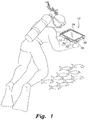
- Fig. 1 of the drawings provides an environmental view of the pressurized waterproof case for an electronic device 10 in use during a dive, with reference being made as well to the perspective view of the exemplary embodiment of the case in Fig. 2 for a more detailed view.
- the case 10 includes a relatively thin, flat housing 12 adapted for waterproof containment of a touch-screen tablet computer C or the like, e.g., an iPad®, smartphone, or similar device.
- a thin, flat housing 12 is shown in Figs. 1 and 2 , this is not limiting.
- the housing can have any suitable shape that improves functionality or ease of use.
- the housing may have ergonomic features, such as handles or contours that make the case easier to grip.
- the housing can be constructed from any suitable material or materials including metal, plastic, alloy, or composite. In some instances, positively buoyant plastics can be desirable.
- the housing can include surface coatings, such as non-slip materials, which make the case easier to grip.
- the housing 12 can be formed of a rigid back panel 14, a rigid front frame or panel 16 opposite the back panel 14, mutually opposed rigid side panels 18, 20 extending between the back panel 14 and the front frame 16 to provide a space therebetween for the computer C, and an end panel 22.
- the various panels 14 through 22 can be imperviously sealed to each another by any suitable sealing technique (e.g., a cement or adhesive forming a watertight and fluid-tight seal), and can define an enclosure or internal volume 24 adapted for the placement of a touch-screen electronic device, such as the tablet computer C, therein.
- the various panels 14 through 22 may be formed of any suitably waterproof material of sufficient strength, and the panels 14 through 22 may be transparent, translucent, or opaque, as only the screen of the computer device C need be observed by the user of the case 10.
- clear or translucent acrylic sheet material may be used to form the panels 14 through 22, although polycarbonate or any other suitable material can be used.
- the use of plastics provides for the transmission of radio frequencies therethrough, allowing the computer C contained within the case 10 to communicate with other devices through conventional means (e.g., Bluetooth®) often provided with such computers.
- the housing 12 may be formed as a unitary, monolithic structure by injection molding, blow molding, or other plastics manufacturing processes, or may be formed from composites or other non-corrosive materials by any conventional process. Accordingly, the housing can be formed from any suitable number of pieces ranging from one to many that are connected using any suitable manufacturing process or processes.
- the front frame 16 includes a large opening 26 therethrough.
- the opening 26 is covered and sealed by a thin, flexible, transparent touch-screen operation membrane or panel 28.
- the flexible and transparent touch-screen panel 28 enables the user of the case 10 to apply pressure to any point on the membrane or panel 28 to contact the underlying portion of the touch-screen of the computer C, thereby operating the computer in its sealed case 10.
- a removable hatch or cover 30 may be provided opposite the fixed end panel 22, allowing the user of the case 10 to install and remove the computer C. Details of the removable hatch 30 are illustrated in Fig. 3 and discussed further below. Although the removable hatch or cover 30 is shown on a left-hand side of the device, this is not limiting.
- the removable hatch or cover can be located in any suitable location to allow for insertion and removal of the computer C into and from the case 10, respectively.
- any side surface, top surface, or back surface can incorporate a removable hatch or cover to facilitate insertion and removal of the computer C.
- the case 10 can include a clamshell design without removable portions.
- the case 10 is pressurized internally to counteract the external pressure developed by the water at the operating depth of the case.
- the case 10 may include a source of pressurized gas disposed upon one of the panels, e.g., the end panel 22, although the pressurized gas source may communicate with any of the panels 14 through 22 or the removable hatch 30 as desired.
- the pressurized gas source is a small cartridge 32 of carbon dioxide (CO 2 of the type conventionally used for the inflation of life preservers and other inflatable devices.
- a regulator valve 34 is attached to the housing 12 and communicates with the internal volume 24 of the case 10, the cartridge 32 being removably attached to the regulator valve 34.
- the pressurized gas can include any suitable gas or gases, such as carbon dioxide, oxygen, air, nitrogen, argon, helium, etc., or any mixture of gases.
- the regulator valve 34 is adjusted to provide an internal pressure within the case 10 that is slightly higher than the ambient water pressure at the working depth of the case.
- the user of the case 10 can easily adjust the pressure by means of the regulator valve 34 while observing the shape of the flexible panel or membrane 28. If too little pressure is provided to the internal volume 24 of the case 10, the panel 28 will be deflected inward onto the screen of the computer C. If too great a pressure is provided, the panel or membrane 28 will be deflected outward due to the pressure differential between the internal volume 24 of the case 10 and the external water pressure.
- the user of the case 10 need only adjust the regulator periodically to cause the flexible panel or membrane 28 to deflect slightly outward from the case 10.
- the slightly greater pressure within the case 10 not only provides for proper operation of the touch-screen computer C within the case 10, but also prevents the inflow of water into the case 10 in the event of any slight leakage at any point.
- an automatic pressure regulating system (not shown) can be incorporated into the case 10.
- the automatic pressure regulating system can include sensors (not shown) for determining deflection of the flexible panel or membrane 28, and pressure within the case 10 can be adjusted accordingly. For instance, if uniform inward deflection of the flexible panel or membrane 28 is detected, the automatic pressure regulating system can increase the pressure within the case 10 to prevent the flexible panel or membrane 28 from contacting the touch-screen of the computer C and rendering it inoperative.
- the automatic pressure regulating system can decrease the pressure within the case 10 to prevent structural damage to the flexible panel or membrane 28 and to improve functionality and response to the user's tactile inputs.
- the user can freely change their depth in the water without having to manually adjust the pressure within the case.
- the automatic pressure regulating system can include a first pressure sensor attached to an internal surface of the case 10 and a second pressure sensor attached to an external surface of the case 10. By comparing the signals from the two pressure sensors, the pressure regulating system can determine if pressure within the case should be increased or decreased. To accomplish this comparison of pressures, the automatic pressure regulating system can include a microprocessor capable of receiving input signals from various sensors and generating output commands based on those signals. For instance, the microprocessor can compare a first signal from the first pressure sensor and a second signal from the second pressure sensor. Based on this comparison, the microprocessor can send a command signal to the pressure regulator valve instructing it to open or close. Opening and closing of the valve can be accomplished with a servo motor or other suitable device.
- the microprocessor can be an independent component. Alternately, the capability of the computer C can be leveraged as part of the pressure regulating system, thereby allowing the computer C to serve as the microprocessor for the pressure regulating system. Similarly, the pressure regulating system can leverage other features built into the computer, such as pressure or temperature sensors and battery power to operate sensors and indicator lights and to actuate pressure valves.
- an automatic pressure regulating system having a microprocessor is described herein, this is not limiting.
- mechanical devices capable of comparing two pressures and maintaining a desired pressure differential between the two pressures i.e. internal and external housing pressures
- This configuration while mechanical in nature, can provide automatic pressure regulation that requires little or no manual control.
- the gas pressure developed within the case 10 with the computer C sealed therein will result in the pressure within the computer C being equal to the pressure within the case 10, but outside of the computer C.
- no net pressure is developed on either side of the touch screen of the computer C.
- the slightly greater pressure within the case 10 relative to the external water pressure results in the flexible membrane or panel 28 being deflected away from the touch screen of the computer C contained within the case 10.
- a diver using the pressurized waterproof case 10 with the computer C sealed therein need only apply localized fingertip pressure to the flexible panel or membrane 28 to deflect it inward to the screen of the computer C, thereby controlling the computer C by means of its touch screen.
- the case 10 can also include a pressure relief valve 36 disposed upon one of the panels of the case 10 that communicates with the internal volume 24 of the case.
- a pressure relief valve 36 is illustrated in Figs. 1 through 3 extending from the end panel 22, but the valve 36 may be installed in any of the panels comprising the housing 12 of the case 10.
- the pressure relief valve 36 can be a one-way check valve that opens to release gas when gas pressure inside the case 10 is greater than external pressure applied by water, but precludes the inflow of water into the case 10 should the external pressure be greater than the pressure within the case 10 at any point.
- the pressure relief valve 36 is set to allow only a relatively small differential pressure between the interior of the case 10 and the external pressure in order to preclude excessive distension of the flexible panel or membrane 28.
- Fig. 3 of the drawings illustrates an alternative embodiment of the pressurized waterproof case, designated as case 110.
- the case 110 of Fig. 3 can be formed of the same panel components as the case 10 of Figs. 1 and 2 , i.e., panels 14 through 22, and can have the opening 26 in the front frame or panel 16 sealed by the flexible panel or membrane 28.
- One difference between the case 10 of Figs. 1 and 2 and the case 110 of Fig. 3 is the source of pressurized gas used to provide gas pressure to the internal volume 24 of the case 110.
- An external line 38 is removably connected to a fitting 40 of the end panel 22 of the case 110 of Fig. 3 to deliver air or other gas to the case 110.
- a conventional manually activated button or other control may be provided to allow the user to add pressure to the case 110 as desired.
- the addition of pressure can be controlled by the automatic pressure regulating system.
- the source of the gas may be the diver's breathing air, as provided by a pressure regulator to provide the desired pressure to the case 110 and a shutoff valve at the diver's air tank for use in the event of excessive airflow to the case 110.
- Such regulators and shutoff valves are conventional, and accordingly are not illustrated.
- Other sources of pressurized gas for the case 10 may be provided as desired, e.g., a separate, remotely disposed gas cylinder containing air, CO 2 , etc., carried by the diver.
- Fig. 3 also provides an illustration of one example of the removable hatch 30 for the cases 10 and 110.
- the hatch 30 and its mechanism shown in Figs. 2 and 3 are identical for the two cases 10 and 110 but is not limiting.
- the hatch 30 may be formed of material identical to or dissimilar to the materials used to form the remainder of the case 10, so long as it is rigid.
- a resilient waterproof seal 42 e.g., an O-ring, resilient flange, etc., is installed about the open end or edge of the case 10, the rigid hatch 30 clamping tightly against the resilient seal 42 to seal the computer C within the case 10 and to prevent water from entering therein.
- the slightly higher pressure within the case 10 also assists in preventing water entry, as noted further above, since any leakage would tend to be gas escaping from the case as opposed to water entering the case.
- the latching means used to secure the hatch 30 tightly to the case 10 may comprise an over-center type latch 44 disposed at the end of each of the side panels 18 and 20 adjacent the open end of the case 10, and cooperating catches 46 disposed upon the opposite ends of the hatch 30, or some other means of tightly securing the hatch 30 to the case 10 or 110, e.g., threaded hold-down bolts, snap-fit, or any other suitable mechanical joint.
- the case 10, 110 may also include a push button control assembly gland 35 extending through the housing 12 with a push button control rod or other push button assembly that will align with and operate an on/off power switch on the computer C so that the diver can power the electronic device on or off without removing the electronic device from the case. Similar features can be incorporated into the case to allow for other buttons, switches, or features of the computer to be operated without removing the device from the case.
- the pressurized waterproof case 10 or 110 can be used by initially removing the hatch 30 from the remainder of the case, activating the computer C and setting any mechanical controls necessary, then placing the computer C within the case 10 or 110, and securing the hatch 30 in place.
- the air or other gas supply is then connected to the case 10 or 110, if not previously accomplished.
- the diver may then open the regulator slightly, e.g., regulator 34 for the case 10 of Figs. 1 and 2 , and begin the dive.
- the diver may periodically adjust the regulator 34 as he or she descends in order to maintain a slightly greater pressure within the case 10, 110 than the pressure at the corresponding depth.
- the diver may elect to keep the regulator 34 closed until reaching the desired depth, and then open the regulator upon reaching the working depth in order to pressurize the case 110 slightly above the ambient pressure developed by the water at the working depth. It is recognized that the diver may ascend and/or descend to some degree during the dive, and the diver may adjust the pressure within the case 10 manually as needed in order to prevent the flexible transparent touch-screen operation panel 28 from bearing against the touch screen of the computer C contained within the case 10 or 110. Even the relatively small gas cartridge 32 of the case 10 embodiment of Figs. 1 and 2 provides sufficient gas for the duration of the dive, as the case 10 is sealed unless pressure therein exceeds external pressure to some predetermined degree.
- the relief valve 36 When the pressure is properly adjusted at a constant level, the relief valve 36 is closed and the pressure within the sealed case 10 is relatively constant with no additional gas being required to maintain the pressure. When the diver ascends, the relief valve 36 vents excessive pressure from the case 10 or 110, requiring no further operation on the part of the diver. Pressure will remain slightly above ambient within the case 10 or 110 even as the diver surfaces. The diver may then open the latches 44 and remove the hatch 30 of the case 10, 110 to retrieve the computer C from the case, and download or otherwise work conventionally with the data entered into the computer C during the dive.
- the flexible membrane or panel 28 may be made from vinyl or any other suitable material that is substantially transparent and flexible.
- the case 10, 110 preferably is substantially fluid-tight, i.e., water cannot leak in, and the pressurized gas (carbon dioxide, air, oxygen, an inert gas, etc.) cannot leak out.
- the flexible membrane or panel 28 can be attached to the case 10, 110 using any suitable method such as, for example, ultrasonic welding. Alternately, suitable adhesives, mechanical fasteners, or a combination thereof can be used.
- the pressurized waterproof case may be provided as a dedicated device in combination with a tablet computer or the like for use underwater.
- the tablet computer C can be permanently sealed inside the case 10, 110, which would no longer require the hatch 30.
- the case 10, 110 may be equipped with a regulator valve 34 adapted for connection to a source of pressurized gas, and with a relief valve 36 to release gas when the pressure inside the case 10, 110 exceeds ambient pressure by too much.
- the tablet computer C may be connected to fittings or connectors mounted in the rigid walls of the case 10, 110, e.g., a power adapter for charging the battery, a USB port, etc., the fittings or connectors being equipped with appropriate waterproof or fluid-tight seals.
- the case can facilitate underwater communications, such as calling, text messaging, emailing, data transfers, or file sharing between the computer and any other device.
- the case 10 can include a communication device that enables through-water communication with any suitable underwater device or device at the surface (e.g. computer, submarine, submersible, dive watch, dive boat, sensor, unmanned surface vessel, acoustic underwater modem, etc.).
- a first case can facilitate communications between a first diver holding the first case and a second diver holding a second case, where the communication devices in the first and second cases are compatible.
- a first case can facilitate communications between a diver with the first case and a surface vessel, such as an unmanned surface vessel as described in U.S. Patent Application No.
- a first case can facilitate communications from a diver holding a first case to a fixed underwater listening station including an acoustic transmitter and hydrophone array that are compatible with the communication device in the first case.
- the communication device can include separate components for transmitting and receiving signals, or the components can be integrated.
- the communication device can include a component, such as an acoustic hydrophone, for receiving underwater acoustic communications.
- Acoustic hydrophones typically include a piezoelectric transducer that generates an electrical signal when subjected to a pressure change.
- a message such as a call, text message, email, data, or file can be encoded by a microprocessor into an acoustic wave that can be transmitted by an acoustic transmitter through water to a hydrophone.
- the hydrophone can output an electrical signal that can be decoded by a microprocessor.
- the hydrophone should be exposed to the water through which it is receiving acoustic waves. Therefore, if the case includes a hydrophone, a first portion of the hydrophone should extend from the case into the water.
- a second portion of the hydrophone such as the end from which an electrical signal is output, can be housed within the case for protection.
- the communication device can include a component, such as an acoustic transmitter, for transmitting underwater acoustic communications.
- a component such as an acoustic transmitter
- the acoustic transmitter should be exposed to the water through which it is transmitting acoustic waves. Therefore, if the case includes an acoustic transmitter, a first portion of the acoustic transmitter should extend from the case into the water. A second portion of the acoustic transmitter, such as the end where an electrical signal is input, can be housed within the case for protection.
- the communication device can be housed within the case and can be connected to the computer, where "connected" can include a wired connection or a wireless connection, such as Bluetooth or any other suitable method for exchanging data over short distances within the case. Any communications transmitted or received from the computer to the communication device can be recorded, time stamped, or geocoded.
- the computer can include an input for a speaker and microphone that allows the user to communicate verbally with other divers via the computer and communication device.
- the computer can include an input for a push to talk (PTT) system where the user presses a microphone button to talk to other divers and releases the button to listen to other divers.
- PTT push to talk
- the PTT system can be integrated into the diver's mask.
- the computer can be configured to record communications, thereby enhancing underwater data acquisition.
- the case 10 can include a variety of sensors to promote safety and enhance data acquisition.
- the case 10 can include pressure sensors, depth sensors, temperature sensors, salinity sensors, force sensors, vibration sensors, photo optic sensors, fluid property sensors, and/or position sensors.
- the sensors can be connected to the microprocessor located within the case. Alternately, the sensors can be connected to the computer C. Those skilled in the art will appreciate that any other necessary components required for data acquisition can be included as separate components in the case 10 or incorporated directly into the computer C.
- the computer can be configured to run software applications.
- a software application can enable a guided tour of underwater features.
- the user can arrive at a location of interest and enter the water with the case described herein.
- the user can run the software application on the computer C.
- the user can manually input their diving location.
- the computer can determine the user's geographical location based on GPS, triangulation, or any other suitable method.
- the software application can load a guided tour based on the user's location. For example, a guided tour may direct the user to noteworthy objects and sites such as shipwrecks and reefs.
- the software application can also provide flora and fauna guides that are easily accessible and tailored to the user's location.
- the computer can receive location-based information from a GPS receiver located within or attached to the case or from a GPS receiver within the computer.
- GPS is a satellite-based navigation system made up of a network of 24 satellites placed into orbit by the U.S. Department of Defense. Civilian GPS uses a frequency of 1575.42 MHz in the UHF band.
- the radio signals can pass through clouds, glass, and plastic, but cannot pass through most solid objects, such as buildings or mountains. When passing through liquids, such as seawater, the radio signals are heavily attenuated. Consequently, the GPS receiver will only function when the case is above water. When the case is below water, the computer can still receive location-based information through the communication device via acoustic waves. For example, location-based information can be acquired by a GPS receiver located above the surface of the water, and that location-based information can be encoded and transmitted to the case located underwater via acoustic waves.
- this apparatus could be used in mountainous terrain at high elevations where precipitation, such as snow, is common.
Landscapes
- Engineering & Computer Science (AREA)
- Theoretical Computer Science (AREA)
- Microelectronics & Electronic Packaging (AREA)
- Computer Hardware Design (AREA)
- Human Computer Interaction (AREA)
- Physics & Mathematics (AREA)
- General Engineering & Computer Science (AREA)
- General Physics & Mathematics (AREA)
- Casings For Electric Apparatus (AREA)
- Telephone Set Structure (AREA)
Claims (14)
- Boîtier étanche aux fluides (10) pour dispositif électronique à écran tactile, comprenant :un logement (12) qui est sensiblement étanche aux fluides ;un panneau souple (28) sur une surface du logement (12) configuré pour permettre l'actionnement d'un écran tactile d'un dispositif électronique situé dans le logement (12) ; etune vanne de régulation (34) connectée au logement (12), où la vanne de régulation (34) est configurée pour admettre du gaz sous pression dans le logement (12) afin d'écarter le panneau souple de l'écran tactile de l'écran tactile.
- Boîtier étanche aux fluides selon la revendication 1, comprenant en outre un système de régulation automatique de la pression configuré pour contrôler la vanne de régulation (34).
- Boîtier étanche aux fluides selon la revendication 2, dans lequel le système de régulation automatique de la pression comprend : un premier capteur de pression connecté à une surface interne du logement (12) et un second capteur de pression connecté à une surface externe du logement (12).
- Boîtier étanche aux fluides selon la revendication 1, comprenant en outre un dispositif électronique à écran tactile à l'intérieur du logement (12).
- Boîtier étanche aux fluides selon la revendication 4, dans lequel le dispositif électronique à écran tactile comprend une application logicielle configurée pour proposer des circuits de visites subaquatiques.
- Boîtier étanche aux fluides selon la revendication 4, dans lequel l'application logicielle est configurée pour sélectionner un circuit de visite subaquatique en se basant sur une position géographique du dispositif électronique.
- Boîtier étanche aux fluides selon la revendication 5, dans lequel l'application logicielle est configurée pour délivrer des alertes à un utilisateur.
- Boîtier étanche aux fluides selon la revendication 1, dans lequel le panneau souple comprend du vinyle.
- Boîtier étanche aux fluides selon la revendication 4, comprenant en outre une trappe configurée pour permettre le retrait du dispositif à écran tactile du logement (12).
- Boîtier étanche aux fluides selon la revendication 1, comprenant en outre un capteur de pression, un capteur de température, un capteur de profondeur, un récepteur GPS ou un capteur de salinité rattachés au logement (12).
- Boîtier étanche aux fluides selon la revendication 1, comprenant en outre un dispositif de communication rattaché au logement (12).
- Boîtier étanche aux fluides selon la revendication 11, dans lequel le dispositif de communication est configuré pour transmettre ou recevoir des signaux acoustiques.
- Boîtier étanche aux fluides selon la revendication 12, dans lequel le dispositif de communication est connecté à un dispositif électronique à écran tactile.
- Boîtier étanche aux fluides selon la revendication 13, dans lequel le dispositif électronique à écran tactile est configuré pour envoyer ou recevoir des messages de texte, des courriels, des données ou des fichiers au moyen du dispositif de communication.
Applications Claiming Priority (3)
| Application Number | Priority Date | Filing Date | Title |
|---|---|---|---|
| US13/193,295 US20130027849A1 (en) | 2011-07-28 | 2011-07-28 | Pressurized waterproof case for electronic device |
| PCT/US2011/046085 WO2013015818A1 (fr) | 2011-07-28 | 2011-08-01 | Boîtier étanche pressurisé pour un dispositif électronique |
| PCT/US2012/038822 WO2013015866A1 (fr) | 2011-07-28 | 2012-05-21 | Boîtier sous pression étanche à l'eau pour dispositif électronique |
Publications (3)
| Publication Number | Publication Date |
|---|---|
| EP2736809A1 EP2736809A1 (fr) | 2014-06-04 |
| EP2736809A4 EP2736809A4 (fr) | 2015-01-21 |
| EP2736809B1 true EP2736809B1 (fr) | 2016-04-06 |
Family
ID=47597047
Family Applications (1)
| Application Number | Title | Priority Date | Filing Date |
|---|---|---|---|
| EP12817671.6A Not-in-force EP2736809B1 (fr) | 2011-07-28 | 2012-05-21 | Boîtier sous pression étanche à l'eau pour dispositif électronique |
Country Status (4)
| Country | Link |
|---|---|
| US (1) | US20130027849A1 (fr) |
| EP (1) | EP2736809B1 (fr) |
| AU (1) | AU2012287490B2 (fr) |
| WO (2) | WO2013015818A1 (fr) |
Families Citing this family (27)
| Publication number | Priority date | Publication date | Assignee | Title |
|---|---|---|---|---|
| US7933122B2 (en) | 2007-06-06 | 2011-04-26 | Otter Products, Llc | Protective enclosure for a computer |
| CN102387328A (zh) * | 2010-09-01 | 2012-03-21 | 三洋科技中心(深圳)有限公司 | 图像显示装置 |
| US20180046229A1 (en) * | 2012-01-30 | 2018-02-15 | Xciel, Inc. | Explosion proof assembly |
| US8867198B2 (en) * | 2012-06-04 | 2014-10-21 | William Steele | Protective case for a tablet computer |
| WO2014197870A1 (fr) * | 2013-06-06 | 2014-12-11 | Otter Products, Llc | Mécanisme d'isolation acoustique avec membrane |
| GB2516023A (en) * | 2013-07-07 | 2015-01-14 | Andrew Russell Coughlin | Shallow depth diving equipment housing |
| US9307131B1 (en) * | 2013-08-16 | 2016-04-05 | Damien Breen | Display system using mountable tablet enclosure |
| ES1089931Y (es) * | 2013-08-21 | 2013-12-13 | Mendez Jordi Llanes | Sistema automático de regulación de volumen para fundas y/o contenedores herméticos destinados a la protección de aparatos electrónicos y/o eléctricos |
| US20150144509A1 (en) * | 2013-11-26 | 2015-05-28 | Bianca M. Viscusi | System and device for transport and delivery of a medication |
| US9155368B2 (en) * | 2014-01-02 | 2015-10-13 | Chi-Yuan Chang | Waterproof protection pouch for mobile devices |
| FI126230B (en) * | 2014-01-31 | 2016-08-31 | Alleco Oy | Method and device for protection and use of touch-sensitive devices under water |
| US20150349831A1 (en) * | 2014-06-02 | 2015-12-03 | Two Technologies, Inc. | Protective case for an electronic device |
| PL3062035T3 (pl) * | 2015-02-27 | 2017-10-31 | Greenonetec Solarindustrie Gmbh | Kolektor słoneczny |
| WO2016181382A1 (fr) * | 2015-05-11 | 2016-11-17 | Stahl Noam | Accessoire de communication sous-marin |
| US9545140B1 (en) | 2015-07-19 | 2017-01-17 | Otter Products, Llc | Protective enclosure for an electronic device |
| CN206043729U (zh) * | 2016-06-30 | 2017-03-29 | 刘颂东 | 电子产品触摸屏在水下环境内高灵敏度触控装置 |
| WO2018148401A1 (fr) * | 2017-02-08 | 2018-08-16 | Underwater Audio LLC | Dispositifs électroniques portatifs améliorés |
| US10420406B2 (en) | 2017-02-16 | 2019-09-24 | Otter Products, Llc | Protective cover for electronic device |
| US10404042B2 (en) * | 2017-03-03 | 2019-09-03 | Klas Technologies Limited | Modular power distribution travel system |
| CN108514201B (zh) * | 2018-04-28 | 2024-10-01 | 达沃客(珠海)智能科技有限公司 | 一种紧凑型、软硬结合的智能终端产品防护壳 |
| US11476883B2 (en) | 2019-02-14 | 2022-10-18 | Apple Inc. | Electronic devices having optical and audio components |
| US11470934B2 (en) * | 2019-05-15 | 2022-10-18 | Targus International Llc | Portable electronic device case with thermal vents |
| CN113260180B (zh) * | 2021-06-30 | 2021-10-01 | 深之蓝(天津)水下智能科技有限公司 | 水下密封舱及具有电子元件的水下设备 |
| US12273138B2 (en) * | 2021-10-28 | 2025-04-08 | Otter Products, Llc | Protective enclosure for an electronic device |
| WO2024071937A1 (fr) * | 2022-09-27 | 2024-04-04 | 아티슨앤오션 주식회사 | Dispositif étanche de plongée et procédé de mesure de profondeur de l'eau l'utilisant |
| CN118939088B (zh) * | 2024-08-22 | 2025-05-27 | 深圳市硕控智能科技有限公司 | 一种基于密封结构的水下计算机 |
| CN118866447B (zh) * | 2024-09-26 | 2024-11-29 | 成都天瀚智能科技有限公司 | 一种加固笔记本屏线防水结构 |
Family Cites Families (14)
| Publication number | Priority date | Publication date | Assignee | Title |
|---|---|---|---|---|
| US4465189A (en) * | 1983-04-11 | 1984-08-14 | American Safety Flight Systems, Inc. | Waterproof container |
| US4853722A (en) * | 1987-08-14 | 1989-08-01 | Sea Fathoms Industries | Method and apparatus for extending the depth range of underwater equipment |
| US4771299A (en) * | 1987-10-29 | 1988-09-13 | Sea Fathoms Industries | Method and apparatus for underwater operation of non-waterproof equipment |
| US7535799B2 (en) * | 1999-10-04 | 2009-05-19 | H2O Audio, Inc. | Protective housing for an audio device |
| US7263032B2 (en) * | 1999-10-04 | 2007-08-28 | H2O Audio, Inc. | System for housing an audio system in an aquatic environment |
| JP2001333814A (ja) * | 2000-05-30 | 2001-12-04 | Asahi Research Kk | 防水ケース |
| US6646864B2 (en) * | 2001-11-19 | 2003-11-11 | Otter Products, Llc | Protective case for touch screen device |
| US7907394B2 (en) * | 2001-11-19 | 2011-03-15 | Otter Products, Llc | Protective enclosure for touch screen device |
| US6659274B2 (en) * | 2001-12-14 | 2003-12-09 | Hewlett-Packard Development Company, L.P. | Waterproof casing for Hewlett-Packard Jornada portable personal computer |
| JP4492481B2 (ja) * | 2005-08-16 | 2010-06-30 | 株式会社ニコン | カメラハウジング |
| US20070215663A1 (en) * | 2006-03-15 | 2007-09-20 | Chongson Ian S | Water resistant case for electronic devices |
| TWI352567B (en) * | 2008-04-21 | 2011-11-11 | Wistron Corp | Waterproof casing |
| US20100310194A1 (en) * | 2009-06-08 | 2010-12-09 | Roy Archambault | Waterproof, handheld electronic device enclosure |
| US8155510B2 (en) * | 2010-07-06 | 2012-04-10 | SalamanderSkinz, LLC | Universal underwater enclosure for cameras and camcorders |
-
2011
- 2011-07-28 US US13/193,295 patent/US20130027849A1/en not_active Abandoned
- 2011-08-01 WO PCT/US2011/046085 patent/WO2013015818A1/fr not_active Ceased
-
2012
- 2012-05-21 AU AU2012287490A patent/AU2012287490B2/en not_active Ceased
- 2012-05-21 WO PCT/US2012/038822 patent/WO2013015866A1/fr not_active Ceased
- 2012-05-21 EP EP12817671.6A patent/EP2736809B1/fr not_active Not-in-force
Also Published As
| Publication number | Publication date |
|---|---|
| AU2012287490B2 (en) | 2017-02-23 |
| EP2736809A4 (fr) | 2015-01-21 |
| EP2736809A1 (fr) | 2014-06-04 |
| WO2013015866A1 (fr) | 2013-01-31 |
| AU2012287490A1 (en) | 2014-02-27 |
| WO2013015818A1 (fr) | 2013-01-31 |
| HK1198754A1 (zh) | 2015-06-05 |
| US20130027849A1 (en) | 2013-01-31 |
Similar Documents
| Publication | Publication Date | Title |
|---|---|---|
| AU2012287490B2 (en) | Pressurized waterproof case for electronic device | |
| US20130025904A1 (en) | Pressurized waterproof case electronic device | |
| US8166904B2 (en) | Delivery systems for pressure protecting and delivering a submerged payload and methods for using the same | |
| US5956291A (en) | Underwater diving assistant apparatus | |
| US20030135326A1 (en) | System for underwater GPS navigation | |
| US7477207B2 (en) | Diving mask with embedded computer system | |
| US8281731B2 (en) | Delivery systems for pressure protecting and delivering a submerged payload and methods for using the same | |
| KR20200004447A (ko) | 음향 부품용 보호 부재 및 방수 케이스 | |
| WO2008144244A3 (fr) | Dispositif de plongee autonome dote de capacites de navigation et de communication sous-marines | |
| US20140346078A1 (en) | Fluid sealable protective case for portable electronic devices | |
| US10536181B2 (en) | Providing a seal for a protective mobile device case | |
| Sanfilippo et al. | The Aquatic Surface Robot (AnSweR), a lightweight, low cost, multipurpose unmanned research vessel | |
| Rahman et al. | A modular sensor suite for underwater reconstruction | |
| HK1198754B (en) | Pressurized waterproof case for electronic device | |
| US12619214B2 (en) | Interface and control of underwater robotics, instruments, and sensors from a human occupied submerged space | |
| FR2988370A1 (fr) | Procede et dispositif, submersible et securise, de collecte, visualisation, traitement, communication et edition, collaborative, en temps reel, de contenus sous-marins, assiste par un robot | |
| US20160357197A1 (en) | Adaptive Pressure Balancer | |
| CN113492956A (zh) | 一种水下机器人 | |
| FR3057366B1 (fr) | Systeme multimedia subaquatique | |
| CN215752966U (zh) | 一种水下机器人 | |
| JP2001037518A (ja) | 電気、電子機器、精密機器の防護カバー | |
| Rodríguez et al. | Mini AUV, a platform for future use on marine research for the Spanish Research Council? | |
| Burt | Autoprobe: An autonomous observational platform for microstructure studies | |
| Aras et al. | Auto depth control for underwater remotely operated vehicles using a flexible ballast tank system | |
| US20120075195A1 (en) | Digital text-based communication and recording device for divers |
Legal Events
| Date | Code | Title | Description |
|---|---|---|---|
| PUAI | Public reference made under article 153(3) epc to a published international application that has entered the european phase |
Free format text: ORIGINAL CODE: 0009012 |
|
| 17P | Request for examination filed |
Effective date: 20140226 |
|
| AK | Designated contracting states |
Kind code of ref document: A1 Designated state(s): AL AT BE BG CH CY CZ DE DK EE ES FI FR GB GR HR HU IE IS IT LI LT LU LV MC MK MT NL NO PL PT RO RS SE SI SK SM TR |
|
| DAX | Request for extension of the european patent (deleted) | ||
| A4 | Supplementary search report drawn up and despatched |
Effective date: 20141222 |
|
| RIC1 | Information provided on ipc code assigned before grant |
Ipc: A45C 11/00 20060101ALI20141216BHEP Ipc: A45C 11/22 20060101ALI20141216BHEP Ipc: A45C 13/00 20060101ALI20141216BHEP Ipc: B65D 81/18 20060101ALI20141216BHEP Ipc: B65B 31/00 20060101AFI20141216BHEP Ipc: A45C 13/02 20060101ALI20141216BHEP |
|
| REG | Reference to a national code |
Ref country code: HK Ref legal event code: DE Ref document number: 1198754 Country of ref document: HK |
|
| GRAP | Despatch of communication of intention to grant a patent |
Free format text: ORIGINAL CODE: EPIDOSNIGR1 |
|
| INTG | Intention to grant announced |
Effective date: 20151012 |
|
| GRAS | Grant fee paid |
Free format text: ORIGINAL CODE: EPIDOSNIGR3 |
|
| GRAA | (expected) grant |
Free format text: ORIGINAL CODE: 0009210 |
|
| AK | Designated contracting states |
Kind code of ref document: B1 Designated state(s): AL AT BE BG CH CY CZ DE DK EE ES FI FR GB GR HR HU IE IS IT LI LT LU LV MC MK MT NL NO PL PT RO RS SE SI SK SM TR |
|
| REG | Reference to a national code |
Ref country code: GB Ref legal event code: FG4D |
|
| REG | Reference to a national code |
Ref country code: AT Ref legal event code: REF Ref document number: 787523 Country of ref document: AT Kind code of ref document: T Effective date: 20160415 Ref country code: CH Ref legal event code: EP |
|
| REG | Reference to a national code |
Ref country code: IE Ref legal event code: FG4D |
|
| REG | Reference to a national code |
Ref country code: DE Ref legal event code: R096 Ref document number: 602012016852 Country of ref document: DE |
|
| REG | Reference to a national code |
Ref country code: FR Ref legal event code: PLFP Year of fee payment: 5 |
|
| REG | Reference to a national code |
Ref country code: LT Ref legal event code: MG4D Ref country code: NL Ref legal event code: MP Effective date: 20160406 |
|
| REG | Reference to a national code |
Ref country code: AT Ref legal event code: MK05 Ref document number: 787523 Country of ref document: AT Kind code of ref document: T Effective date: 20160406 |
|
| PG25 | Lapsed in a contracting state [announced via postgrant information from national office to epo] |
Ref country code: BE Free format text: LAPSE BECAUSE OF NON-PAYMENT OF DUE FEES Effective date: 20160531 |
|
| PG25 | Lapsed in a contracting state [announced via postgrant information from national office to epo] |
Ref country code: NL Free format text: LAPSE BECAUSE OF FAILURE TO SUBMIT A TRANSLATION OF THE DESCRIPTION OR TO PAY THE FEE WITHIN THE PRESCRIBED TIME-LIMIT Effective date: 20160406 |
|
| PG25 | Lapsed in a contracting state [announced via postgrant information from national office to epo] |
Ref country code: NO Free format text: LAPSE BECAUSE OF FAILURE TO SUBMIT A TRANSLATION OF THE DESCRIPTION OR TO PAY THE FEE WITHIN THE PRESCRIBED TIME-LIMIT Effective date: 20160706 Ref country code: PL Free format text: LAPSE BECAUSE OF FAILURE TO SUBMIT A TRANSLATION OF THE DESCRIPTION OR TO PAY THE FEE WITHIN THE PRESCRIBED TIME-LIMIT Effective date: 20160406 Ref country code: IS Free format text: LAPSE BECAUSE OF FAILURE TO SUBMIT A TRANSLATION OF THE DESCRIPTION OR TO PAY THE FEE WITHIN THE PRESCRIBED TIME-LIMIT Effective date: 20160806 Ref country code: LT Free format text: LAPSE BECAUSE OF FAILURE TO SUBMIT A TRANSLATION OF THE DESCRIPTION OR TO PAY THE FEE WITHIN THE PRESCRIBED TIME-LIMIT Effective date: 20160406 Ref country code: FI Free format text: LAPSE BECAUSE OF FAILURE TO SUBMIT A TRANSLATION OF THE DESCRIPTION OR TO PAY THE FEE WITHIN THE PRESCRIBED TIME-LIMIT Effective date: 20160406 |
|
| REG | Reference to a national code |
Ref country code: HK Ref legal event code: GR Ref document number: 1198754 Country of ref document: HK |
|
| PG25 | Lapsed in a contracting state [announced via postgrant information from national office to epo] |
Ref country code: RS Free format text: LAPSE BECAUSE OF FAILURE TO SUBMIT A TRANSLATION OF THE DESCRIPTION OR TO PAY THE FEE WITHIN THE PRESCRIBED TIME-LIMIT Effective date: 20160406 Ref country code: HR Free format text: LAPSE BECAUSE OF FAILURE TO SUBMIT A TRANSLATION OF THE DESCRIPTION OR TO PAY THE FEE WITHIN THE PRESCRIBED TIME-LIMIT Effective date: 20160406 Ref country code: GR Free format text: LAPSE BECAUSE OF FAILURE TO SUBMIT A TRANSLATION OF THE DESCRIPTION OR TO PAY THE FEE WITHIN THE PRESCRIBED TIME-LIMIT Effective date: 20160707 Ref country code: LV Free format text: LAPSE BECAUSE OF FAILURE TO SUBMIT A TRANSLATION OF THE DESCRIPTION OR TO PAY THE FEE WITHIN THE PRESCRIBED TIME-LIMIT Effective date: 20160406 Ref country code: PT Free format text: LAPSE BECAUSE OF FAILURE TO SUBMIT A TRANSLATION OF THE DESCRIPTION OR TO PAY THE FEE WITHIN THE PRESCRIBED TIME-LIMIT Effective date: 20160808 Ref country code: ES Free format text: LAPSE BECAUSE OF FAILURE TO SUBMIT A TRANSLATION OF THE DESCRIPTION OR TO PAY THE FEE WITHIN THE PRESCRIBED TIME-LIMIT Effective date: 20160406 Ref country code: AT Free format text: LAPSE BECAUSE OF FAILURE TO SUBMIT A TRANSLATION OF THE DESCRIPTION OR TO PAY THE FEE WITHIN THE PRESCRIBED TIME-LIMIT Effective date: 20160406 Ref country code: SE Free format text: LAPSE BECAUSE OF FAILURE TO SUBMIT A TRANSLATION OF THE DESCRIPTION OR TO PAY THE FEE WITHIN THE PRESCRIBED TIME-LIMIT Effective date: 20160406 |
|
| PG25 | Lapsed in a contracting state [announced via postgrant information from national office to epo] |
Ref country code: IT Free format text: LAPSE BECAUSE OF FAILURE TO SUBMIT A TRANSLATION OF THE DESCRIPTION OR TO PAY THE FEE WITHIN THE PRESCRIBED TIME-LIMIT Effective date: 20160406 Ref country code: BE Free format text: LAPSE BECAUSE OF FAILURE TO SUBMIT A TRANSLATION OF THE DESCRIPTION OR TO PAY THE FEE WITHIN THE PRESCRIBED TIME-LIMIT Effective date: 20160406 |
|
| REG | Reference to a national code |
Ref country code: CH Ref legal event code: PL |
|
| REG | Reference to a national code |
Ref country code: DE Ref legal event code: R097 Ref document number: 602012016852 Country of ref document: DE |
|
| PG25 | Lapsed in a contracting state [announced via postgrant information from national office to epo] |
Ref country code: CH Free format text: LAPSE BECAUSE OF NON-PAYMENT OF DUE FEES Effective date: 20160531 Ref country code: MC Free format text: LAPSE BECAUSE OF FAILURE TO SUBMIT A TRANSLATION OF THE DESCRIPTION OR TO PAY THE FEE WITHIN THE PRESCRIBED TIME-LIMIT Effective date: 20160406 Ref country code: RO Free format text: LAPSE BECAUSE OF FAILURE TO SUBMIT A TRANSLATION OF THE DESCRIPTION OR TO PAY THE FEE WITHIN THE PRESCRIBED TIME-LIMIT Effective date: 20160406 Ref country code: SK Free format text: LAPSE BECAUSE OF FAILURE TO SUBMIT A TRANSLATION OF THE DESCRIPTION OR TO PAY THE FEE WITHIN THE PRESCRIBED TIME-LIMIT Effective date: 20160406 Ref country code: EE Free format text: LAPSE BECAUSE OF FAILURE TO SUBMIT A TRANSLATION OF THE DESCRIPTION OR TO PAY THE FEE WITHIN THE PRESCRIBED TIME-LIMIT Effective date: 20160406 Ref country code: LI Free format text: LAPSE BECAUSE OF NON-PAYMENT OF DUE FEES Effective date: 20160531 Ref country code: CZ Free format text: LAPSE BECAUSE OF FAILURE TO SUBMIT A TRANSLATION OF THE DESCRIPTION OR TO PAY THE FEE WITHIN THE PRESCRIBED TIME-LIMIT Effective date: 20160406 Ref country code: DK Free format text: LAPSE BECAUSE OF FAILURE TO SUBMIT A TRANSLATION OF THE DESCRIPTION OR TO PAY THE FEE WITHIN THE PRESCRIBED TIME-LIMIT Effective date: 20160406 |
|
| PLBE | No opposition filed within time limit |
Free format text: ORIGINAL CODE: 0009261 |
|
| STAA | Information on the status of an ep patent application or granted ep patent |
Free format text: STATUS: NO OPPOSITION FILED WITHIN TIME LIMIT |
|
| REG | Reference to a national code |
Ref country code: IE Ref legal event code: MM4A |
|
| PG25 | Lapsed in a contracting state [announced via postgrant information from national office to epo] |
Ref country code: SM Free format text: LAPSE BECAUSE OF FAILURE TO SUBMIT A TRANSLATION OF THE DESCRIPTION OR TO PAY THE FEE WITHIN THE PRESCRIBED TIME-LIMIT Effective date: 20160406 |
|
| 26N | No opposition filed |
Effective date: 20170110 |
|
| REG | Reference to a national code |
Ref country code: FR Ref legal event code: PLFP Year of fee payment: 6 |
|
| PG25 | Lapsed in a contracting state [announced via postgrant information from national office to epo] |
Ref country code: SI Free format text: LAPSE BECAUSE OF FAILURE TO SUBMIT A TRANSLATION OF THE DESCRIPTION OR TO PAY THE FEE WITHIN THE PRESCRIBED TIME-LIMIT Effective date: 20160406 Ref country code: IE Free format text: LAPSE BECAUSE OF NON-PAYMENT OF DUE FEES Effective date: 20160521 |
|
| PGFP | Annual fee paid to national office [announced via postgrant information from national office to epo] |
Ref country code: FR Payment date: 20170525 Year of fee payment: 6 Ref country code: GB Payment date: 20170530 Year of fee payment: 6 Ref country code: DE Payment date: 20170530 Year of fee payment: 6 |
|
| PG25 | Lapsed in a contracting state [announced via postgrant information from national office to epo] |
Ref country code: HU Free format text: LAPSE BECAUSE OF FAILURE TO SUBMIT A TRANSLATION OF THE DESCRIPTION OR TO PAY THE FEE WITHIN THE PRESCRIBED TIME-LIMIT; INVALID AB INITIO Effective date: 20120521 |
|
| PG25 | Lapsed in a contracting state [announced via postgrant information from national office to epo] |
Ref country code: MT Free format text: LAPSE BECAUSE OF NON-PAYMENT OF DUE FEES Effective date: 20160531 Ref country code: MK Free format text: LAPSE BECAUSE OF FAILURE TO SUBMIT A TRANSLATION OF THE DESCRIPTION OR TO PAY THE FEE WITHIN THE PRESCRIBED TIME-LIMIT Effective date: 20160406 Ref country code: LU Free format text: LAPSE BECAUSE OF NON-PAYMENT OF DUE FEES Effective date: 20160521 Ref country code: CY Free format text: LAPSE BECAUSE OF FAILURE TO SUBMIT A TRANSLATION OF THE DESCRIPTION OR TO PAY THE FEE WITHIN THE PRESCRIBED TIME-LIMIT Effective date: 20160406 |
|
| PG25 | Lapsed in a contracting state [announced via postgrant information from national office to epo] |
Ref country code: BG Free format text: LAPSE BECAUSE OF FAILURE TO SUBMIT A TRANSLATION OF THE DESCRIPTION OR TO PAY THE FEE WITHIN THE PRESCRIBED TIME-LIMIT Effective date: 20160406 |
|
| PG25 | Lapsed in a contracting state [announced via postgrant information from national office to epo] |
Ref country code: TR Free format text: LAPSE BECAUSE OF FAILURE TO SUBMIT A TRANSLATION OF THE DESCRIPTION OR TO PAY THE FEE WITHIN THE PRESCRIBED TIME-LIMIT Effective date: 20160406 Ref country code: AL Free format text: LAPSE BECAUSE OF FAILURE TO SUBMIT A TRANSLATION OF THE DESCRIPTION OR TO PAY THE FEE WITHIN THE PRESCRIBED TIME-LIMIT Effective date: 20160406 |
|
| REG | Reference to a national code |
Ref country code: DE Ref legal event code: R119 Ref document number: 602012016852 Country of ref document: DE |
|
| GBPC | Gb: european patent ceased through non-payment of renewal fee |
Effective date: 20180521 |
|
| PG25 | Lapsed in a contracting state [announced via postgrant information from national office to epo] |
Ref country code: GB Free format text: LAPSE BECAUSE OF NON-PAYMENT OF DUE FEES Effective date: 20180521 Ref country code: FR Free format text: LAPSE BECAUSE OF NON-PAYMENT OF DUE FEES Effective date: 20180531 Ref country code: DE Free format text: LAPSE BECAUSE OF NON-PAYMENT OF DUE FEES Effective date: 20181201 |