EP2737181B1 - System zur verbesserten hybridisierung von auf sonnenwärme sowie auf biomasse und fossilen brennstoffen basierenden stromsytemen - Google Patents
System zur verbesserten hybridisierung von auf sonnenwärme sowie auf biomasse und fossilen brennstoffen basierenden stromsytemen Download PDFInfo
- Publication number
- EP2737181B1 EP2737181B1 EP12756818.6A EP12756818A EP2737181B1 EP 2737181 B1 EP2737181 B1 EP 2737181B1 EP 12756818 A EP12756818 A EP 12756818A EP 2737181 B1 EP2737181 B1 EP 2737181B1
- Authority
- EP
- European Patent Office
- Prior art keywords
- thermal energy
- solar
- tes
- unit
- htf
- Prior art date
- Legal status (The legal status is an assumption and is not a legal conclusion. Google has not performed a legal analysis and makes no representation as to the accuracy of the status listed.)
- Not-in-force
Links
- 239000002028 Biomass Substances 0.000 title claims description 71
- 238000009396 hybridization Methods 0.000 title claims description 20
- 239000002803 fossil fuel Substances 0.000 title claims description 5
- 239000013529 heat transfer fluid Substances 0.000 claims description 79
- 150000003839 salts Chemical class 0.000 claims description 56
- 239000012530 fluid Substances 0.000 claims description 20
- 238000004146 energy storage Methods 0.000 claims description 11
- 239000000446 fuel Substances 0.000 claims description 10
- 239000003949 liquefied natural gas Substances 0.000 claims description 8
- 239000013589 supplement Substances 0.000 claims description 7
- 239000003915 liquefied petroleum gas Substances 0.000 claims description 6
- 239000002699 waste material Substances 0.000 claims description 5
- 238000002485 combustion reaction Methods 0.000 claims description 4
- 238000012546 transfer Methods 0.000 claims description 3
- 239000003245 coal Substances 0.000 claims description 2
- 238000004519 manufacturing process Methods 0.000 claims description 2
- 239000002551 biofuel Substances 0.000 claims 1
- 239000007787 solid Substances 0.000 claims 1
- 239000002918 waste heat Substances 0.000 claims 1
- 230000005611 electricity Effects 0.000 description 9
- 238000013461 design Methods 0.000 description 7
- 238000010586 diagram Methods 0.000 description 7
- 230000005855 radiation Effects 0.000 description 7
- VNWKTOKETHGBQD-UHFFFAOYSA-N methane Chemical compound C VNWKTOKETHGBQD-UHFFFAOYSA-N 0.000 description 6
- 239000003921 oil Substances 0.000 description 6
- 230000004044 response Effects 0.000 description 6
- 238000003860 storage Methods 0.000 description 6
- 238000013459 approach Methods 0.000 description 5
- 238000006243 chemical reaction Methods 0.000 description 3
- 230000000295 complement effect Effects 0.000 description 3
- 230000006872 improvement Effects 0.000 description 3
- 238000000034 method Methods 0.000 description 3
- 239000003345 natural gas Substances 0.000 description 3
- 239000000243 solution Substances 0.000 description 3
- 230000008901 benefit Effects 0.000 description 2
- 239000000284 extract Substances 0.000 description 2
- 238000010304 firing Methods 0.000 description 2
- 239000012782 phase change material Substances 0.000 description 2
- 230000008569 process Effects 0.000 description 2
- 230000000087 stabilizing effect Effects 0.000 description 2
- 230000001502 supplementing effect Effects 0.000 description 2
- OKTJSMMVPCPJKN-UHFFFAOYSA-N Carbon Chemical compound [C] OKTJSMMVPCPJKN-UHFFFAOYSA-N 0.000 description 1
- 239000004215 Carbon black (E152) Substances 0.000 description 1
- JOCBASBOOFNAJA-UHFFFAOYSA-N N-tris(hydroxymethyl)methyl-2-aminoethanesulfonic acid Chemical compound OCC(CO)(CO)NCCS(O)(=O)=O JOCBASBOOFNAJA-UHFFFAOYSA-N 0.000 description 1
- 239000007994 TES buffer Substances 0.000 description 1
- 239000000872 buffer Substances 0.000 description 1
- 230000001351 cycling effect Effects 0.000 description 1
- 230000009977 dual effect Effects 0.000 description 1
- 230000000694 effects Effects 0.000 description 1
- 230000008030 elimination Effects 0.000 description 1
- 238000003379 elimination reaction Methods 0.000 description 1
- 238000005516 engineering process Methods 0.000 description 1
- 239000007789 gas Substances 0.000 description 1
- 229910002804 graphite Inorganic materials 0.000 description 1
- 239000010439 graphite Substances 0.000 description 1
- 238000010438 heat treatment Methods 0.000 description 1
- 229930195733 hydrocarbon Natural products 0.000 description 1
- 150000002430 hydrocarbons Chemical class 0.000 description 1
- 230000010354 integration Effects 0.000 description 1
- 238000012423 maintenance Methods 0.000 description 1
- 238000002844 melting Methods 0.000 description 1
- 230000008018 melting Effects 0.000 description 1
- 239000010815 organic waste Substances 0.000 description 1
- 230000003071 parasitic effect Effects 0.000 description 1
- 230000000704 physical effect Effects 0.000 description 1
- 238000005086 pumping Methods 0.000 description 1
- 229920006395 saturated elastomer Polymers 0.000 description 1
- 230000001932 seasonal effect Effects 0.000 description 1
- 238000004513 sizing Methods 0.000 description 1
- 239000002023 wood Substances 0.000 description 1
Images




Classifications
-
- F—MECHANICAL ENGINEERING; LIGHTING; HEATING; WEAPONS; BLASTING
- F24—HEATING; RANGES; VENTILATING
- F24S—SOLAR HEAT COLLECTORS; SOLAR HEAT SYSTEMS
- F24S20/00—Solar heat collectors specially adapted for particular uses or environments
- F24S20/40—Solar heat collectors combined with other heat sources, e.g. using electrical heating or heat from ambient air
-
- F—MECHANICAL ENGINEERING; LIGHTING; HEATING; WEAPONS; BLASTING
- F01—MACHINES OR ENGINES IN GENERAL; ENGINE PLANTS IN GENERAL; STEAM ENGINES
- F01K—STEAM ENGINE PLANTS; STEAM ACCUMULATORS; ENGINE PLANTS NOT OTHERWISE PROVIDED FOR; ENGINES USING SPECIAL WORKING FLUIDS OR CYCLES
- F01K3/00—Plants characterised by the use of steam or heat accumulators, or intermediate steam heaters, therein
- F01K3/004—Accumulation in the liquid branch of the circuit
-
- F—MECHANICAL ENGINEERING; LIGHTING; HEATING; WEAPONS; BLASTING
- F01—MACHINES OR ENGINES IN GENERAL; ENGINE PLANTS IN GENERAL; STEAM ENGINES
- F01K—STEAM ENGINE PLANTS; STEAM ACCUMULATORS; ENGINE PLANTS NOT OTHERWISE PROVIDED FOR; ENGINES USING SPECIAL WORKING FLUIDS OR CYCLES
- F01K3/00—Plants characterised by the use of steam or heat accumulators, or intermediate steam heaters, therein
- F01K3/12—Plants characterised by the use of steam or heat accumulators, or intermediate steam heaters, therein having two or more accumulators
-
- F—MECHANICAL ENGINEERING; LIGHTING; HEATING; WEAPONS; BLASTING
- F22—STEAM GENERATION
- F22B—METHODS OF STEAM GENERATION; STEAM BOILERS
- F22B1/00—Methods of steam generation characterised by form of heating method
- F22B1/006—Methods of steam generation characterised by form of heating method using solar heat
-
- Y—GENERAL TAGGING OF NEW TECHNOLOGICAL DEVELOPMENTS; GENERAL TAGGING OF CROSS-SECTIONAL TECHNOLOGIES SPANNING OVER SEVERAL SECTIONS OF THE IPC; TECHNICAL SUBJECTS COVERED BY FORMER USPC CROSS-REFERENCE ART COLLECTIONS [XRACs] AND DIGESTS
- Y02—TECHNOLOGIES OR APPLICATIONS FOR MITIGATION OR ADAPTATION AGAINST CLIMATE CHANGE
- Y02E—REDUCTION OF GREENHOUSE GAS [GHG] EMISSIONS, RELATED TO ENERGY GENERATION, TRANSMISSION OR DISTRIBUTION
- Y02E10/00—Energy generation through renewable energy sources
- Y02E10/40—Solar thermal energy, e.g. solar towers
-
- Y—GENERAL TAGGING OF NEW TECHNOLOGICAL DEVELOPMENTS; GENERAL TAGGING OF CROSS-SECTIONAL TECHNOLOGIES SPANNING OVER SEVERAL SECTIONS OF THE IPC; TECHNICAL SUBJECTS COVERED BY FORMER USPC CROSS-REFERENCE ART COLLECTIONS [XRACs] AND DIGESTS
- Y02—TECHNOLOGIES OR APPLICATIONS FOR MITIGATION OR ADAPTATION AGAINST CLIMATE CHANGE
- Y02E—REDUCTION OF GREENHOUSE GAS [GHG] EMISSIONS, RELATED TO ENERGY GENERATION, TRANSMISSION OR DISTRIBUTION
- Y02E20/00—Combustion technologies with mitigation potential
- Y02E20/14—Combined heat and power generation [CHP]
-
- Y—GENERAL TAGGING OF NEW TECHNOLOGICAL DEVELOPMENTS; GENERAL TAGGING OF CROSS-SECTIONAL TECHNOLOGIES SPANNING OVER SEVERAL SECTIONS OF THE IPC; TECHNICAL SUBJECTS COVERED BY FORMER USPC CROSS-REFERENCE ART COLLECTIONS [XRACs] AND DIGESTS
- Y02—TECHNOLOGIES OR APPLICATIONS FOR MITIGATION OR ADAPTATION AGAINST CLIMATE CHANGE
- Y02E—REDUCTION OF GREENHOUSE GAS [GHG] EMISSIONS, RELATED TO ENERGY GENERATION, TRANSMISSION OR DISTRIBUTION
- Y02E50/00—Technologies for the production of fuel of non-fossil origin
- Y02E50/10—Biofuels, e.g. bio-diesel
-
- Y—GENERAL TAGGING OF NEW TECHNOLOGICAL DEVELOPMENTS; GENERAL TAGGING OF CROSS-SECTIONAL TECHNOLOGIES SPANNING OVER SEVERAL SECTIONS OF THE IPC; TECHNICAL SUBJECTS COVERED BY FORMER USPC CROSS-REFERENCE ART COLLECTIONS [XRACs] AND DIGESTS
- Y02—TECHNOLOGIES OR APPLICATIONS FOR MITIGATION OR ADAPTATION AGAINST CLIMATE CHANGE
- Y02P—CLIMATE CHANGE MITIGATION TECHNOLOGIES IN THE PRODUCTION OR PROCESSING OF GOODS
- Y02P80/00—Climate change mitigation technologies for sector-wide applications
- Y02P80/10—Efficient use of energy, e.g. using compressed air or pressurized fluid as energy carrier
- Y02P80/15—On-site combined power, heat or cool generation or distribution, e.g. combined heat and power [CHP] supply
Definitions
- the present invention relates to Combined Heat and Power (CHP) applications.
- CHP Combined Heat and Power
- Electricity generation from solar energy suffers from a fundamental problem of reliance on an unpredictable and variable source of energy. To some extent this problem can be mitigated by using thermal energy storage systems which can extend the availability of solar energy beyond daylight hours, and even to 24 hours if the storage is sufficiently large, but after periods of low or no radiation even the storage system will not be able to provide the energy required to render the plant as capable of delivering base-load electricity reliably. Put simply, it is not feasible realistically to build an electric generation capacity using solar energy that is fully base-load capable and dispatch manageable without supplementing the solar energy with some other source of thermal energy.
- This source is usually a fossil fuel such as liquefied natural gas (LNG), liquefied petroleum gas (LPG) or distillates. These fuels are favoured because the boilers and heaters which burn these fuels can be designed for quick start and stop, cycling duties and low load duties. These characteristics complement the variability and unpredictability of solar radiation, and yield a stable generation capacity.
- LNG liquefied natural gas
- LPG liquefied petroleum gas
- Effective hybridization of a thermal solar field with a biomass system involves melding two distinct sources of thermal energy, and delivering that energy seamlessly to the power block for the generation of electricity.
- a general scheme of such a process is shown schematically in Fig. 1 .
- thermal energy is obtained from a solar field 10 that uses solar radiation as the prime energy source (CSP) and from a biomass system 11 that uses energy source such as a wood fire, organic waste municipal waste and other non-solar thermal energy sources (BM).
- CSP prime energy source
- BM non-solar thermal energy sources
- the thermal energy from these two distinct sources is fed to a hybridization system 15 that facilitates the combination of two systems that feature different characteristics, namely that solar energy fluctuates in accordance with the sun insolation, while the biomass system is limited in its ability to follow the solar system variations.
- the hybridization system 15 feeds thermal energy which can be eventually used by a turbo-generator 16 that produces electricity 17 or by other thermal energy users.
- Fig. 2 shows schematically a biomass fired boiler 20 arranged in parallel with a solar steam generator 21 and can be used to supplement steam output either partially or completely in times of little or no solar radiation prior to feeding to a turbine (such as 16 in Fig. 1 ).
- a turbine such as 16 in Fig. 1
- Heat transfer fluid 22 from the solar field 10 is fed via a first valve 23 to the solar steam generator 21 and cooler heat transfer fluid 24 is pumped back to the solar field by a pump 25.
- Steam 26 produced by the solar steam generator 21 is fed in parallel with steam produced by the biomass fired boiler 20 to the turbine and condensate 27 is returned to both the biomass fired boiler 20 and the solar steam generator 21 where it is re-heated in an ongoing cycle.
- thermal energy storage (TES) 28 may be coupled to the solar steam generator 21 via a second valve 29.
- Solar thermal energy stored in the TES 28 during daylight hours may be used at night to power the solar steam generator 21 by closing the first valve 23 and opening the second valve 29.
- the biomass boiler turndown is usually limited to 50%-70% of full load.
- the boiler must be kept “hot”, but running it at a minimal load is not feasible.
- Systems employing such an approach need to be kept hot using some sort of external heat source. The resultant energy losses are significant, reducing overall plant conversion efficiency.
- Fig. 3 shows schematically a biomass fired steam super-heater 30 arranged in series with the solar steam generator 21. In other respects the arrangement is the same as shown in Fig. 2 and is therefore not described.
- This configuration aims to overcome one of the efficiency limitations of concentrated solar power based plants, namely the maximum steam temperature that can be achieved. Saturated steam from the solar field can be superheated to 540°C, for example, and thus improve thermal efficiency of the turbine from approximately 39% to 44%.
- the super-heater 30 would need to track the steam output from the solar steam generator and deliver a proportional amount of energy for superheating.
- modulation of biomass boilers is problematic and so this cannot be done effectively.
- this arrangement increases cycle efficiency, it does not assist in stabilizing base-load generation or meeting the changing demand requirements.
- US 2009/205335 discloses a domestic energy supply system wherein the thermal energy of the temperature difference between at least one heat source and at least one heat sink is converted into work by way of a hybrid thermal engine.
- the thermal engine has a fluid cycle with at least two reservoirs, which, in each case as a condenser to be cooled or an evaporator to be heated, are thermally coupled to the heat source or the heat sink.
- US Patent No. 5,444,972 discloses a power plant which uses hydrocarbon fuels in conjunction with solar power to produce electricity.
- An object of the present invention is therefore to provide an improved hybridization system and method that combines and utilizes separate energy sources (thermal, solar and biomass) and thermal energy storage (TES) system, in order to achieve better usage of the energy sources per the specific local needs for electrical power and heating.
- Such an improved hybridization system produces a final outcome that is greater than the sum of the individual outcomes of the component energy sources.
- a hybridization system for use in a hybrid energy plant that comprises a first thermal energy unit powered by a solar field for providing thermal energy to a user via a first heat transfer fluid and a second non-solar thermal energy unit providing thermal energy to said user via a second heat transfer fluid, said hybridization system comprising:
- a hybridization system for use in a hybrid energy plant that comprises a first thermal energy unit powered by solar energy for providing thermal energy to a user via a first heat transfer fluid (HTF) and a second non-solar thermal energy unit providing thermal energy to said user via a second heat transfer fluid, said hybridization system including a mixing unit for mixing the thermal energy of the first heat transfer fluid and the thermal energy of the second heat transfer fluid either directly or indirectly so as to form a unified heat transfer fluid that is fed to the user.
- HTF heat transfer fluid
- the hybridization system is configured to take into consideration the unique operating characteristics of each individual system, yet allow for their efficient hybrid operation in all possible operating modes (solar only, biomass only and hybrid mode at varying ratios). This is achieved while providing sufficient system flexibility to meet the dynamic needs of the grid, performance targets and improve the overall plant utilization.
- a power plant according to the invention especially when operating as a base-load system, must meet stringent requirements of the grid manager including that the system be fully dispatch manageable, , capable of responding rapidly to load demand changes of the grid and capable of responding to fast drops of load without disconnecting from the grid.
- stringent requirements of the grid manager including that the system be fully dispatch manageable, , capable of responding rapidly to load demand changes of the grid and capable of responding to fast drops of load without disconnecting from the grid.
- the overarching consideration in the design of the plant must be the primary objective of delivering stable, fast response, dispatchable power to the grid, as per schedule, the manageability, the quality and the supply agreements with the local/national electrical authority.
- the hybridization system should aim to deliver this result with maximum energy efficiency and at an economically justifiable cost.
- the hybridization system exhibits the following characteristics:
- Fig. 4 shows a first embodiment of a hybrid energy plant 35 having a biomass fired heat transfer fluid (HTF) heater 40 arranged in parallel with the solar field via a third valve 41 and which can be used to supplement thermal output of the solar field either partially or completely in times of little or no solar radiation.
- a fourth valve 42 determines the amount of cooled HTF (typically oil) from the steam generator 21 that is returned to the solar field 10 or, optionally, is fed to the heater 40.
- HTF typically oil
- Biomass fuel and also natural gas or LNG can be used for firing but also any type of fuel that undergoes combustion can be used within the heater and is true all of the systems described herein.
- the hybridization system 15 includes a mixing unit 45 shown in dotted outline, which includes the valves 23, 29,41 and 42 as well as the pump 25, all of which are controlled by a control unit shown schematically as 46.
- the mixing unit 45 serves to mix the thermal energy of the first heat transfer fluid and the thermal energy of the second heat transfer fluid either directly or indirectly so as to form a unified heat transfer fluid that is fed to the user.
- the hot HTF can be used to keep the biomass heaters "hot” when required, so as to reduce start up time.
- Similar negative issues observed in the prior art system shown in Fig. 2 apply to this system as well. Biomass firing cannot be moderated as easily as LNG or NG (natural gas) burners, meaning the turndown ratio is still a major problem as well as the inability of this system to quickly respond to the dynamic load changes of the grid.
- Fig. 5 shows schematically a power plant 50 according to a second embodiment including a biomass fired HTF heater 40 to charge directly (i.e. provide thermal energy to) the TES system 28, in parallel with the CSP's HTF system.
- Steam is generated in the steam generator 21 which, as used herein constitutes a "user", through discharge of the TES 28 to the HTF system as required.
- Molten salt is used as the heat transfer fluid of the biomass heater 40 to charge the TES directly as distinct from the systems shown in Figs. 2 and 3 , where the heater heats HTF, which then heats the molten salt.
- the TES 28 in this embodiment comprises a cold salt tank 52 from which molten salt is pumped to a hot salt tank 53 by a pump 54.
- Thermal energy derived from the heated molten salt is mixed with thermal energy derived from the HTF of the solar field in a salt/HTF heat exchanger 55, which can work in forward and backward flow directions, and can feed the returned relatively cold molten salt to the cold salt tank 52 and heated molten salt to the hot salt tank 53.
- Non-return valves 56 and 57 prevent the molten salt in the respective tanks from flowing back to the salt/HTF heat exchanger 55.
- the valves 29, 41, 42 and pump 25 are controlled by the control unit 46 according to whether thermal energy from the solar HTF. is to be stored in the TES or whether stored thermal energy is to be used to supplement the solar HTF.
- valve 42 When the valve 42 is open and valves 29 and 41 are closed, all cooled HTF (typically oil) from the steam generator 21 is returned to the solar field 10 via the pump 25. If the valves 29 and 42 are closed and the valve 41 is open, the cooled HTF returned by the pump 25 is fed to the salt/HTF heat exchanger 55 where it extracts the heat from the molten salt fed thereto from the hot salt tank 53. This cools the hot molten salt, which returns to the cold salt tank 52, while the heated solar HTF is again fed to the steam generator 21.
- HTF typically oil
- Thermal energy is stored in the TES 28 in the opposite manner by opening the valves 29 and 42 closing the valve 41.
- Hot solar HTF is fed to the salt/HTF heat exchanger 55 where it meets cold molten salt that is fed thereto from the cold salt tank 52.
- the molten salt extracts the heat from the solar HTF and hot molten salt returns to the hot salt tank 53, where its thermal energy is stored so as to be available when there is inadequate high-temperature solar HTF.
- the cooled solar HTF is returned from the salt/HTF heat exchanger 55 via the open valve 29 to the solar field.
- the single heat exchanger 55 is thus used in forward and backward flow directions to complete all mixing and transferring of the thermal energy between the first thermal energy unit 10 and the second non-solar thermal energy unit 11 and the thermal energy storage 28.
- the system uses the thermal energy of the solar field to generate steam directly. Excess energy is passed to the TES system 28, as is done in many conventional solar thermal plant designs.
- the biomass heater 40 directly heats the thermal salts of the TES system, or provides thermal energy to the TES, in parallel with the CSP's HTF/salt heat exchanger 55 so as both to feed energy to the user at a common input thereof and to receive the returned colder HTF from the user via a common output thereof.
- the mixing unit 45 which operates at least over the full working temperature range of the solar field.
- the biomass is burned in a furnace and the hot gasses are primarily used to heat the biomass's HTF (i.e. molten salt), with an economizer attached to the system either to heat incoming air for combustion or the CSP's HTF.
- the biomass heater 40 may heat the thermal salts of the TES system 28 via a heat exchanger (not shown), which allows different types of molten salt to be used in the biomass heater 40 and the TES 28.
- This arrangement differs from regular power plants using biomass fuel in that direct connection between the biomass boiler/heater and the turbine is eliminated. This avoids direct flow of thermal energy from the biomass to the turbine and these two main sub-systems of the plant can thus operate mutually independently at different times and at different loads. A variation of this configuration would allow portion of the thermal energy coming from the biomass heater to be fed directly to the steam generation chain.
- the TES system 28 acts as a buffer for the variation in the solar system.
- the biomass heater 40 operation is decoupled from the demand for steam. This allows the biomass heater to be operated within the identified constraints of these systems while stabilizing the supply of steam. Thermal energy is drawn from the TES system 28 as demanded by the turbine load irrespective of the instantaneous ability of either the biomass system or the CSP system to supply that energy. Additionally, little start-up heat is wasted from the biomass heater 40, as any of the biomass salts not yet at the required high temperature may be recycled to the cold tank via a return line.
- the size of the TES system 28 and biomass heater 40 needs to be optimized for the intended operating schedule. For instance, if the plant is only required to dispatch power for 16 hours of the day at 100%, then the biomass heater 40 may be sized at 66% to operate 24 hours, provided the TES system is sized sufficiently to store the 8 hours of 66% energy. At the same time, the TES system sizing must reflect the proper economics of the solar field as well. Ultimately, economic considerations will determine the relative sizes of the solar field, biomass heater and TES system.
- a mixing system is used. Such mixing includes several pumping devices according to the number of the heat transfer fluids and storing media used, mechanical devices including piping system, vessels and control valves to allow the mixing of the fluid streams and transferring thermal energy between all units of the plant and instrumentation and control devices to control and adjust the operation of all units of the plant.
- the control unit 46 uses several input data sources including from the user, from the first and the second thermal energy units, from the TES and optionally also actual and forecast weather data. The control unit functions to adjust and optimize the operation of all units of the system as well as to start and shut down these units.
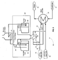
- Fig. 6 shows a hybrid plant 60 according to a third embodiment of the invention relating to a biomass fired salt heater 40 to generate steam and charge the TES system.
- the solar field is used only to charge the TES constituted by the cold and hot molten salt tanks 52 and 53.
- Steam is generated in the salt steam generator 61 through discharge of the TES to the salt system as required.
- This embodiment is similar in concept to the previous embodiment described above with reference to Fig. 5 but reverses the steam generation configuration.
- the steam is generated directly from biomass on the salt side of the TES system and only indirectly from the solar field always via the TES system.
- a variation of this configuration allows portion of the thermal energy coming from the solar field to be fed directly to the steam generation chain.
- the control unit 46 opens and closes control valves 62, 63, 64, 65 and operates pump 66 to store thermal energy in the TES 28 or feed it to the salt steam generator as required.
- the above two embodiments show "split" thermal systems, wherein there is a distinct oil-based heat transfer fluid (HTF) system on the solar side, and a thermal salt system for the storage and biomass side.
- HTF heat transfer fluid
- thermal salt for the storage and biomass side.
- HTF oil-based heat transfer fluid
- One of the critical characteristics of the HTF fluid is that it remains fluid at low ambient temperatures, and this favours the use of thermal oils.
- Critical characteristics for the thermal storage are low cost and high stability and energy content while a low melting point is not as necessary. This favours the use of molten salt.
- HTF and thermal salts are available and can permit a single heat transfer system, which uses the same HTF/molten salt on both the solar side and the TES/biomass side.
- the invention includes a further configuration, as shown in Fig. 7 , for the hybrid CSP and BM system where the above innovative configurations are further improved by use of the same fluid or oil in both the CSP and the BM systems.
- the successful application of these fluids and salts as described below saves considerable investment in heat exchange systems reduces auxiliary power consumption and generally simplifies system configuration and operation.
- This approach is similar to the embodiment shown in Fig. 6 with the improvement of the elimination of the HTF/Salt heat exchangers.
- Another improvement can be obtained by allowing also direct supply of the thermal energy from the CSP to the steam generator (in addition to the charging possibility of the TES from the CSP).
- thermal energy from biomass the same approach can be applied to other sources of thermal energy such as sources based on coal, bio-gas/fuel, liquefied natural gas (LNG), liquefied petroleum gas (LPG) or distillates and on all other kind of fossil fuels.
- LNG liquefied natural gas
- LPG liquefied petroleum gas
- the above described invention allows for the hybridization with these source in hybrid with a solar thermal source in order to create a reliable and efficient baseload power plant that is capable of generating electricity during all year long with full manageability capabilities as per the requirements and discretion of the grid operator.
- TES system comprising a two-tank (hot and cold) storage system as is common in solar thermal plant designs currently
- TES systems such as single TES tank designs (thermocline), concrete and graphite systems, and phase change material (PCM) TES designs.
- PCM phase change material
- all three of the previous embodiments can also be supplemented by superheating, either directly as in the last embodiment or through an extended salt system with a salt/steam super-heater and re-heater.
- the HTF from the biomass and the HTF from the solar field may be mixed prior to being fed to the user.
- the TES 28 uses a two tank configuration, it may use a single tank to store hot fluid as a medium to store the thermal energy.
Landscapes
- Engineering & Computer Science (AREA)
- Mechanical Engineering (AREA)
- General Engineering & Computer Science (AREA)
- Chemical & Material Sciences (AREA)
- Combustion & Propulsion (AREA)
- Life Sciences & Earth Sciences (AREA)
- Sustainable Energy (AREA)
- Sustainable Development (AREA)
- Physics & Mathematics (AREA)
- Thermal Sciences (AREA)
- Engine Equipment That Uses Special Cycles (AREA)
- Heat-Pump Type And Storage Water Heaters (AREA)
Claims (15)
- Hybridisierungssystem (15) zur Verwendung in einem Hybridkraftwerk (35, 50, 60, 70) umfassend eine erste Wärmeenergieanlage betrieben über ein Solarfeld (10) für die Versorgung eines Verbrauchers (16) mit Wärmeenergie über ein erstes Wärmeträgerfluid (HTF) und eine zweite, nicht-solare Wärmeenergieanlage (11) für die Versorgung des Verbrauchers mit Wärmeenergie über ein zweites Wärmeträgerfluid (HTF), wobei das Hybridisierungssystem Folgendes umfasst:eine Wärmeenergiespeichereinheit (TES) (28) und eine Mischeinheit (45), die direkt oder indirekt mit der ersten Wärmeenergieanlage und der zweiten Wärmeenergieanlage für das Empfangen, Speichern und Mischen von Wärmeenergie der ersten Wärmeenergieanlage und der zweiten Wärmeenergieanlage verbunden sind, um entweder direkt oder indirekt ein einheitliches Wärmeträgerfluid (HTF) zu bilden, das an den Verbraucher gespeist wird,wobei die Wärmeenergiespeichereinheit (TES) einen ersten Tank (53) für die Speicherung eines heißen Fluids als Speichermedium für die Wärmeenergie und einen zweiten Tank (52) für die Speicherung des Fluids im kalten Zustand umfasst, undwobei die Mischeinheit (45) für das Mischen der Wärmeenergie, die aus dem heißen Fluid gewonnen wird, mit der Wärmeenergie, die aus dem HTF des Solarfeldes gewonnen wird, konfiguriert ist; dadurch gekennzeichnet, dass:die Mischeinheit (45) eine Steuerungseinheit (46) enthält, die konfiguriert ist, um Daten des Solarfeldes, einschließlich des tatsächlichen und vorhergesagten Wetters, zu verwenden, um die Betriebsparameter des Solarfeldes, der zweiten, nicht-solaren Wärmeenergieanlage und der TES anzupassen und um Daten der TES für die Anpassung der Betriebsparameter der zweiten, nicht-solaren Wärmeenergieanlage zu verwenden, unddie zweite, nicht-solare Wärmeenergieanlage (11) eine Heizvorrichtung (40) enthält, die das Fluid direkt erhitzt oder der TES parallel zu der Wärmeenergie aus dem HTF des Solarfeldes Wärmeenergie liefert, sodass sowohl die TES über einen gemeinsamen Einlass dieser mit Energie gespeist wird als auch das zurückerhaltene, kältere Fluid vom Verbraucher über einen gemeinsamen Auslass dessen empfangen wird.
- System nach Anspruch 1, wobei die zweite, nicht-solare Wärmeenergieanlage (11) mit Biomassekraftstoff, Kohle, Biokraftstoff, Flüssigerdgas (LNG), Flüssiggas (LPG) oder Destillaten und allen anderen Arten fossiler Brennstoffe betrieben wird.
- System nach Anspruch 1 oder 2, wobei das erste Wärmeträgerfluid und das zweite Wärmeträgerfluid identisch sind.
- System nach Anspruch 3, wobei die zweite, nicht-solare Wärmeenergieanlage (11) mit Biomassekraftstoff betrieben wird und das HTF der Biomasse und das HTF des Solarfeldes vor der Speisung an den Verbraucher gemischt werden.
- System nach Anspruch 4, wobei die erste Wärmeenergieanlage und die zweite, nicht-solare Wärmeenergieanlage parallel geschaltet sind, sodass sowohl Energie an den Verbraucher über einen gemeinsamen Einlass dessen gespeist wird als auch das zurückerhaltene, kältere HTF des Verbrauchers über einen gemeinsamen Auslass dessen empfangen wird, wobei dies entweder direkt oder über die TES (28) geschieht, wobei die Mischeinheit zumindest über den gesamten Betriebstemperaturbereich des Solarfeldes arbeitet.
- System nach einem der Ansprüche 1 bis 5, wobei zumindest eine der ersten Wärmeenergieanlage oder der zweiten Wärmeenergieanlage entweder direkt oder über einen Wärmetauscher (61) mit der TES und dem Verbraucher parallel geschaltet ist.
- System nach einem der Ansprüche 1 bis 6, wobei das zweite Wärmeträgerfluid Salzschmelze ist.
- System nach einem der Ansprüche 1 bis 7, wobei die TES dasselbe Fluid wie zumindest eines der Wärmeträgerfluids, die im ersten oder zweiten Wärmeenergiesystem verwendet werden, als ein Wärmeenergiespeichermedium verwendet.
- System nach einem der Ansprüche 1 bis 8, wobei das Wärmeenergiespeichermedium Salzschmelze ist.
- System nach einem der Ansprüche 1 bis 6, wobei die TES ein festes Medium für die Speicherung der Wärmeenergie verwendet.
- System nach einem der Ansprüche 1 bis 6, wobei ein einzelner Wärmetauscher (55) in Vorwärts- und Rückwärtsflussrichtung dafür verwendet wird, um sämtliche Mischungs- und Übertragungsvorgänge der Wärmeenergie zwischen der ersten Wärmeenergieanlage (10) und der zweiten, nicht-solaren Wärmeenergieanlage (11) und dem Wärmeenergiespeicher (28) durchzuführen.
- System nach einem der Ansprüche 1 bis 11, wobei die Steuerungseinheit (46) für die Verwendung von Daten des Verbrauchers zur Anpassung von Betriebsparametern des Solarfeldes, des zweiten, nicht-solaren Wärmeenergiesystems und der TES konfiguriert ist und wobei die Kontrolleinheit optional für die Anpassung und Optimierung des Betriebs der Anlagen des Kraftwerks nach vorgegebenen Prioritäten konfiguriert ist, diese umfassen das Liefern von Wärmeenergie gemäß dem Bedarf des Verbrauchers, die Maximierung der Verwendung freier Solarthermie, die Maximierung der Verwendung entwerteter Wärmeenergie, die Vorbereitung und Optimierung der Menge der benötigten Wärmeenergie in der TES und den Betrieb des zweiten, nicht-solaren Wärmeenergiesystems, um die ersten Wärmeenergieanlagen zu unterstützen.
- System nach einem der Ansprüche 1 bis 12, wobei das erste Wärmeträgerfluid, das zweite Wärmeträgerfluid und das Energiespeichermedium in der TES (28) Salzschmelzen sind.
- System nach einem der Ansprüche 1 bis 13, wobei das zweite, nicht-solare Wärmeenergiesystem durch Abwärme aus Industrieprozessen, Blockheizkraftwerke, Gas-und-Dampf-Kombikraftwerke, Kraftwerke und Müllaufbereitungsanlagen betrieben wird.
- System nach einem der Ansprüche 1 bis 13, wobei dieses darüber hinaus einen Vorwärmer umfasst, der für die Verwendung von entwerteter Wärmeenergie des zweiten, nicht-solaren Wärmeenergiesystems konfiguriert ist, um einströmende Luft für die Verbrennung in dem zweiten, nicht-solaren Wärmeenergiesystem bzw. für das erste HTF zu erhitzen.
Applications Claiming Priority (2)
| Application Number | Priority Date | Filing Date | Title |
|---|---|---|---|
| US201161512000P | 2011-07-27 | 2011-07-27 | |
| PCT/IL2012/000287 WO2013014664A2 (en) | 2011-07-27 | 2012-07-26 | System for improved hybridization of thermal solar and biomass and fossil fuel based energy systems |
Publications (2)
| Publication Number | Publication Date |
|---|---|
| EP2737181A2 EP2737181A2 (de) | 2014-06-04 |
| EP2737181B1 true EP2737181B1 (de) | 2016-02-10 |
Family
ID=46829838
Family Applications (1)
| Application Number | Title | Priority Date | Filing Date |
|---|---|---|---|
| EP12756818.6A Not-in-force EP2737181B1 (de) | 2011-07-27 | 2012-07-26 | System zur verbesserten hybridisierung von auf sonnenwärme sowie auf biomasse und fossilen brennstoffen basierenden stromsytemen |
Country Status (4)
| Country | Link |
|---|---|
| US (1) | US9360234B2 (de) |
| EP (1) | EP2737181B1 (de) |
| CN (1) | CN103890323B (de) |
| WO (1) | WO2013014664A2 (de) |
Families Citing this family (16)
| Publication number | Priority date | Publication date | Assignee | Title |
|---|---|---|---|---|
| US9816491B2 (en) | 2011-09-29 | 2017-11-14 | Solarreserve Technology, Llc | Solar power system and method therefor |
| GB2500060B (en) * | 2012-03-09 | 2014-04-30 | Diamond Engineering Ltd | Renewable energy storage system |
| US20150089945A1 (en) * | 2013-10-01 | 2015-04-02 | Chevron U.S.A., Inc. | Hybrid solar and fuel-fired steam generation system and method |
| US9200622B2 (en) * | 2013-10-07 | 2015-12-01 | The Babcock & Wilcox Company | Solar-nuclear hybrid power plant |
| WO2016077281A1 (en) | 2014-11-14 | 2016-05-19 | Carrier Corporation | Economized cycle with thermal energy storage |
| CN107635815A (zh) * | 2015-04-06 | 2018-01-26 | 日光储备技术有限公司 | 包含热能存储器的电力系统 |
| AU2016315806A1 (en) * | 2015-09-01 | 2018-04-12 | Glasspoint Solar, Inc. | Variable rate steam injection, including via solar power for enhanced oil recovery, and associated systems and methods |
| AT518186B1 (de) * | 2016-06-10 | 2017-08-15 | Univ Wien Tech | Wärmekraftwerk und Verfahren zum Speichern von Wärme |
| WO2018037324A1 (en) * | 2016-08-25 | 2018-03-01 | Shahid Khan | System using hybrid solar-fossil sources for power generation |
| EP3299594A1 (de) * | 2016-09-26 | 2018-03-28 | Siemens Aktiengesellschaft | Integriertes kombisolarkraftzyklus und verfahren |
| DE102017123454A1 (de) * | 2017-10-10 | 2019-04-11 | Bilfinger Engineering & Technologies Gmbh | Verfahren und Anlage zur Nutzung von Sonnenenergie und einem fossilen Brennstoff zur Stromerzeugung |
| US10876765B2 (en) | 2018-11-28 | 2020-12-29 | Element 16 Technologies, Inc. | Systems and methods of thermal energy storage |
| CN109910332B (zh) * | 2019-03-28 | 2021-01-29 | 宁波华冕智能科技有限公司 | 薄膜生产线 |
| CN112646594B (zh) * | 2020-11-10 | 2022-03-18 | 涉县清漳水泥制造有限公司 | 一种可阶梯利用生物质发电的热电联产系统 |
| CN112963212B (zh) * | 2021-04-08 | 2025-04-22 | 清华大学 | 油田汽电联产的低碳能源利用系统 |
| US20250207819A1 (en) * | 2023-12-21 | 2025-06-26 | Schlumberger Technology Corporation | System and method for cooling a load using renewable energy |
Family Cites Families (13)
| Publication number | Priority date | Publication date | Assignee | Title |
|---|---|---|---|---|
| US5444972A (en) * | 1994-04-12 | 1995-08-29 | Rockwell International Corporation | Solar-gas combined cycle electrical generating system |
| US20080022685A1 (en) | 2006-07-25 | 2008-01-31 | Yanong Zhu | Concentrate solar thermal energy electric power plant logic boiler |
| ES2327991B1 (es) * | 2006-08-04 | 2010-07-15 | Abengoa Solar New Technologies, S.A. | Planta de concentracion solar. |
| DE102006040147B4 (de) * | 2006-08-26 | 2013-07-04 | Karl Wohllaib | Hausenergieversorgungsanlage |
| US8661819B2 (en) * | 2008-04-15 | 2014-03-04 | Morningside Venture Investments Limited | Water reclamation system and method |
| CN201486603U (zh) * | 2009-08-28 | 2010-05-26 | 郭清温 | 一种太阳能与生物质联合发电装置 |
| CN101787906B (zh) * | 2010-02-05 | 2012-08-22 | 东南大学 | 一种太阳能和生物质能综合互补的联合热发电系统 |
| CN101968041B (zh) | 2010-09-29 | 2012-05-30 | 武汉凯迪工程技术研究总院有限公司 | 采用生物质锅炉作为辅助热源的太阳能发电方法及系统 |
| US20120102950A1 (en) * | 2010-11-02 | 2012-05-03 | Alliance For Sustainable Energy, Llc. | Solar thermal power plant with the integration of an aeroderivative turbine |
| US20150000277A1 (en) * | 2011-11-30 | 2015-01-01 | Gossamer Space Frames | Solar power plants and energy storage systems for solar power plants |
| NO337357B1 (no) * | 2012-06-28 | 2016-03-29 | Nest As | Anlegg for energiproduksjon |
| WO2014052927A1 (en) * | 2012-09-27 | 2014-04-03 | Gigawatt Day Storage Systems, Inc. | Systems and methods for energy storage and retrieval |
| EP2765357B1 (de) * | 2012-12-13 | 2020-01-08 | General Electric Technology GmbH | Dampfkraftanlage mit einem zusätzlichen flexiblen Solarsystem zur flexiblen Integration von Solarenergie |
-
2012
- 2012-07-26 EP EP12756818.6A patent/EP2737181B1/de not_active Not-in-force
- 2012-07-26 WO PCT/IL2012/000287 patent/WO2013014664A2/en not_active Ceased
- 2012-07-26 CN CN201280037284.0A patent/CN103890323B/zh not_active Expired - Fee Related
- 2012-07-26 US US14/234,997 patent/US9360234B2/en not_active Expired - Fee Related
Also Published As
| Publication number | Publication date |
|---|---|
| CN103890323B (zh) | 2016-04-20 |
| WO2013014664A2 (en) | 2013-01-31 |
| US9360234B2 (en) | 2016-06-07 |
| CN103890323A (zh) | 2014-06-25 |
| EP2737181A2 (de) | 2014-06-04 |
| US20140182576A1 (en) | 2014-07-03 |
| WO2013014664A3 (en) | 2013-07-04 |
Similar Documents
| Publication | Publication Date | Title |
|---|---|---|
| EP2737181B1 (de) | System zur verbesserten hybridisierung von auf sonnenwärme sowie auf biomasse und fossilen brennstoffen basierenden stromsytemen | |
| US11359521B2 (en) | Dispatchable storage combined cycle power plants | |
| Lai et al. | Operation optimization on the large-scale CHP station composed of multiple CHP units and a thermocline heat storage tank | |
| US10808685B2 (en) | Dispatchable combined cycle power plant | |
| US7640746B2 (en) | Method and system integrating solar heat into a regenerative rankine steam cycle | |
| US20120102950A1 (en) | Solar thermal power plant with the integration of an aeroderivative turbine | |
| US20140223906A1 (en) | Solar/gas hybrid power system configurations and methods of use | |
| CN204358954U (zh) | 一种采用导热油传热的储能式清洁能源热水锅炉 | |
| CN203626907U (zh) | 发电站 | |
| US20080127647A1 (en) | Solar-Generated Steam Retrofit for Supplementing Natural-Gas Combustion at Combined Cycle Power Plants | |
| NO337357B1 (no) | Anlegg for energiproduksjon | |
| US20080034757A1 (en) | Method and system integrating solar heat into a regenerative rankine cycle | |
| CN216554042U (zh) | 一种基于熔盐储热的储热耦合火电机组系统 | |
| Jensen et al. | Demonstration of a concentrated solar power and biomass plant for combined heat and power | |
| EP3559559B1 (de) | Dynamisch adaptives kraft-wärme-kopplungssystem und verfahren dafür | |
| US8584465B2 (en) | Method for increasing the efficiency of a power plant which is equipped with a gas turbine, and power plant for carrying out the method | |
| WO2014123537A1 (en) | Solar/gas hybrid power system configurations and methods of use | |
| Cocco et al. | Exergy analysis of concentrating solar systems for heat and power production | |
| CA2964850A1 (en) | Method for compensating load peaks during energy generation and/or for generating electrical energy and/or for generating hydrogen, and a storage power plant | |
| Green et al. | Nuclear hybrid energy system: Molten salt energy storage | |
| Stark et al. | Approaches for dispatchable biomass plants with particular focus on steam storage devices | |
| US20230163622A1 (en) | Hybrid energy storage systems | |
| Burdenkova et al. | Optimization of schemes and ways to expand the adjustment range for the power supply of combined heat and power plants | |
| US9127653B2 (en) | Solar thermal installation and method for operating a solar thermal installation | |
| Rodriguez-Arango | Proposal Of Optimized Solutions For Joint Use And Hybridization Of Energy Storage Systems And Combined Cycles Or Renewable Energy Plants |
Legal Events
| Date | Code | Title | Description |
|---|---|---|---|
| PUAI | Public reference made under article 153(3) epc to a published international application that has entered the european phase |
Free format text: ORIGINAL CODE: 0009012 |
|
| 17P | Request for examination filed |
Effective date: 20140130 |
|
| AK | Designated contracting states |
Kind code of ref document: A2 Designated state(s): AL AT BE BG CH CY CZ DE DK EE ES FI FR GB GR HR HU IE IS IT LI LT LU LV MC MK MT NL NO PL PT RO RS SE SI SK SM TR |
|
| DAX | Request for extension of the european patent (deleted) | ||
| REG | Reference to a national code |
Ref country code: DE Ref legal event code: R079 Ref document number: 602012014721 Country of ref document: DE Free format text: PREVIOUS MAIN CLASS: F01K0003000000 Ipc: F22B0001000000 |
|
| GRAP | Despatch of communication of intention to grant a patent |
Free format text: ORIGINAL CODE: EPIDOSNIGR1 |
|
| RIC1 | Information provided on ipc code assigned before grant |
Ipc: F22B 1/00 20060101AFI20150717BHEP Ipc: F01K 3/00 20060101ALI20150717BHEP Ipc: F24J 2/00 20140101ALI20150717BHEP Ipc: F01K 3/12 20060101ALI20150717BHEP |
|
| INTG | Intention to grant announced |
Effective date: 20150811 |
|
| GRAS | Grant fee paid |
Free format text: ORIGINAL CODE: EPIDOSNIGR3 |
|
| GRAA | (expected) grant |
Free format text: ORIGINAL CODE: 0009210 |
|
| AK | Designated contracting states |
Kind code of ref document: B1 Designated state(s): AL AT BE BG CH CY CZ DE DK EE ES FI FR GB GR HR HU IE IS IT LI LT LU LV MC MK MT NL NO PL PT RO RS SE SI SK SM TR |
|
| REG | Reference to a national code |
Ref country code: GB Ref legal event code: FG4D |
|
| REG | Reference to a national code |
Ref country code: AT Ref legal event code: REF Ref document number: 774837 Country of ref document: AT Kind code of ref document: T Effective date: 20160215 Ref country code: CH Ref legal event code: EP |
|
| REG | Reference to a national code |
Ref country code: IE Ref legal event code: FG4D |
|
| REG | Reference to a national code |
Ref country code: DE Ref legal event code: R096 Ref document number: 602012014721 Country of ref document: DE |
|
| REG | Reference to a national code |
Ref country code: LT Ref legal event code: MG4D |
|
| REG | Reference to a national code |
Ref country code: NL Ref legal event code: MP Effective date: 20160210 |
|
| REG | Reference to a national code |
Ref country code: AT Ref legal event code: MK05 Ref document number: 774837 Country of ref document: AT Kind code of ref document: T Effective date: 20160210 |
|
| REG | Reference to a national code |
Ref country code: FR Ref legal event code: PLFP Year of fee payment: 5 |
|
| PG25 | Lapsed in a contracting state [announced via postgrant information from national office to epo] |
Ref country code: HR Free format text: LAPSE BECAUSE OF FAILURE TO SUBMIT A TRANSLATION OF THE DESCRIPTION OR TO PAY THE FEE WITHIN THE PRESCRIBED TIME-LIMIT Effective date: 20160210 Ref country code: GR Free format text: LAPSE BECAUSE OF FAILURE TO SUBMIT A TRANSLATION OF THE DESCRIPTION OR TO PAY THE FEE WITHIN THE PRESCRIBED TIME-LIMIT Effective date: 20160511 Ref country code: IT Free format text: LAPSE BECAUSE OF FAILURE TO SUBMIT A TRANSLATION OF THE DESCRIPTION OR TO PAY THE FEE WITHIN THE PRESCRIBED TIME-LIMIT Effective date: 20160210 Ref country code: FI Free format text: LAPSE BECAUSE OF FAILURE TO SUBMIT A TRANSLATION OF THE DESCRIPTION OR TO PAY THE FEE WITHIN THE PRESCRIBED TIME-LIMIT Effective date: 20160210 Ref country code: ES Free format text: LAPSE BECAUSE OF FAILURE TO SUBMIT A TRANSLATION OF THE DESCRIPTION OR TO PAY THE FEE WITHIN THE PRESCRIBED TIME-LIMIT Effective date: 20160210 Ref country code: NO Free format text: LAPSE BECAUSE OF FAILURE TO SUBMIT A TRANSLATION OF THE DESCRIPTION OR TO PAY THE FEE WITHIN THE PRESCRIBED TIME-LIMIT Effective date: 20160510 |
|
| PG25 | Lapsed in a contracting state [announced via postgrant information from national office to epo] |
Ref country code: PT Free format text: LAPSE BECAUSE OF FAILURE TO SUBMIT A TRANSLATION OF THE DESCRIPTION OR TO PAY THE FEE WITHIN THE PRESCRIBED TIME-LIMIT Effective date: 20160613 Ref country code: LT Free format text: LAPSE BECAUSE OF FAILURE TO SUBMIT A TRANSLATION OF THE DESCRIPTION OR TO PAY THE FEE WITHIN THE PRESCRIBED TIME-LIMIT Effective date: 20160210 Ref country code: SE Free format text: LAPSE BECAUSE OF FAILURE TO SUBMIT A TRANSLATION OF THE DESCRIPTION OR TO PAY THE FEE WITHIN THE PRESCRIBED TIME-LIMIT Effective date: 20160210 Ref country code: IS Free format text: LAPSE BECAUSE OF FAILURE TO SUBMIT A TRANSLATION OF THE DESCRIPTION OR TO PAY THE FEE WITHIN THE PRESCRIBED TIME-LIMIT Effective date: 20160610 Ref country code: PL Free format text: LAPSE BECAUSE OF FAILURE TO SUBMIT A TRANSLATION OF THE DESCRIPTION OR TO PAY THE FEE WITHIN THE PRESCRIBED TIME-LIMIT Effective date: 20160210 Ref country code: NL Free format text: LAPSE BECAUSE OF FAILURE TO SUBMIT A TRANSLATION OF THE DESCRIPTION OR TO PAY THE FEE WITHIN THE PRESCRIBED TIME-LIMIT Effective date: 20160210 Ref country code: LV Free format text: LAPSE BECAUSE OF FAILURE TO SUBMIT A TRANSLATION OF THE DESCRIPTION OR TO PAY THE FEE WITHIN THE PRESCRIBED TIME-LIMIT Effective date: 20160210 Ref country code: AT Free format text: LAPSE BECAUSE OF FAILURE TO SUBMIT A TRANSLATION OF THE DESCRIPTION OR TO PAY THE FEE WITHIN THE PRESCRIBED TIME-LIMIT Effective date: 20160210 Ref country code: RS Free format text: LAPSE BECAUSE OF FAILURE TO SUBMIT A TRANSLATION OF THE DESCRIPTION OR TO PAY THE FEE WITHIN THE PRESCRIBED TIME-LIMIT Effective date: 20160210 |
|
| PG25 | Lapsed in a contracting state [announced via postgrant information from national office to epo] |
Ref country code: EE Free format text: LAPSE BECAUSE OF FAILURE TO SUBMIT A TRANSLATION OF THE DESCRIPTION OR TO PAY THE FEE WITHIN THE PRESCRIBED TIME-LIMIT Effective date: 20160210 Ref country code: DK Free format text: LAPSE BECAUSE OF FAILURE TO SUBMIT A TRANSLATION OF THE DESCRIPTION OR TO PAY THE FEE WITHIN THE PRESCRIBED TIME-LIMIT Effective date: 20160210 |
|
| PGFP | Annual fee paid to national office [announced via postgrant information from national office to epo] |
Ref country code: CH Payment date: 20160726 Year of fee payment: 5 |
|
| REG | Reference to a national code |
Ref country code: DE Ref legal event code: R097 Ref document number: 602012014721 Country of ref document: DE |
|
| PG25 | Lapsed in a contracting state [announced via postgrant information from national office to epo] |
Ref country code: SM Free format text: LAPSE BECAUSE OF FAILURE TO SUBMIT A TRANSLATION OF THE DESCRIPTION OR TO PAY THE FEE WITHIN THE PRESCRIBED TIME-LIMIT Effective date: 20160210 Ref country code: CZ Free format text: LAPSE BECAUSE OF FAILURE TO SUBMIT A TRANSLATION OF THE DESCRIPTION OR TO PAY THE FEE WITHIN THE PRESCRIBED TIME-LIMIT Effective date: 20160210 Ref country code: SK Free format text: LAPSE BECAUSE OF FAILURE TO SUBMIT A TRANSLATION OF THE DESCRIPTION OR TO PAY THE FEE WITHIN THE PRESCRIBED TIME-LIMIT Effective date: 20160210 Ref country code: RO Free format text: LAPSE BECAUSE OF FAILURE TO SUBMIT A TRANSLATION OF THE DESCRIPTION OR TO PAY THE FEE WITHIN THE PRESCRIBED TIME-LIMIT Effective date: 20160210 |
|
| PLBE | No opposition filed within time limit |
Free format text: ORIGINAL CODE: 0009261 |
|
| STAA | Information on the status of an ep patent application or granted ep patent |
Free format text: STATUS: NO OPPOSITION FILED WITHIN TIME LIMIT |
|
| PG25 | Lapsed in a contracting state [announced via postgrant information from national office to epo] |
Ref country code: BE Free format text: LAPSE BECAUSE OF FAILURE TO SUBMIT A TRANSLATION OF THE DESCRIPTION OR TO PAY THE FEE WITHIN THE PRESCRIBED TIME-LIMIT Effective date: 20160210 |
|
| 26N | No opposition filed |
Effective date: 20161111 |
|
| PG25 | Lapsed in a contracting state [announced via postgrant information from national office to epo] |
Ref country code: BG Free format text: LAPSE BECAUSE OF FAILURE TO SUBMIT A TRANSLATION OF THE DESCRIPTION OR TO PAY THE FEE WITHIN THE PRESCRIBED TIME-LIMIT Effective date: 20160510 Ref country code: SI Free format text: LAPSE BECAUSE OF FAILURE TO SUBMIT A TRANSLATION OF THE DESCRIPTION OR TO PAY THE FEE WITHIN THE PRESCRIBED TIME-LIMIT Effective date: 20160210 |
|
| PG25 | Lapsed in a contracting state [announced via postgrant information from national office to epo] |
Ref country code: MC Free format text: LAPSE BECAUSE OF FAILURE TO SUBMIT A TRANSLATION OF THE DESCRIPTION OR TO PAY THE FEE WITHIN THE PRESCRIBED TIME-LIMIT Effective date: 20160210 |
|
| REG | Reference to a national code |
Ref country code: IE Ref legal event code: MM4A |
|
| REG | Reference to a national code |
Ref country code: FR Ref legal event code: PLFP Year of fee payment: 6 |
|
| PG25 | Lapsed in a contracting state [announced via postgrant information from national office to epo] |
Ref country code: IE Free format text: LAPSE BECAUSE OF NON-PAYMENT OF DUE FEES Effective date: 20160726 |
|
| PG25 | Lapsed in a contracting state [announced via postgrant information from national office to epo] |
Ref country code: LU Free format text: LAPSE BECAUSE OF NON-PAYMENT OF DUE FEES Effective date: 20160726 |
|
| REG | Reference to a national code |
Ref country code: CH Ref legal event code: PL |
|
| PG25 | Lapsed in a contracting state [announced via postgrant information from national office to epo] |
Ref country code: CH Free format text: LAPSE BECAUSE OF NON-PAYMENT OF DUE FEES Effective date: 20170731 Ref country code: LI Free format text: LAPSE BECAUSE OF NON-PAYMENT OF DUE FEES Effective date: 20170731 |
|
| PG25 | Lapsed in a contracting state [announced via postgrant information from national office to epo] |
Ref country code: HU Free format text: LAPSE BECAUSE OF FAILURE TO SUBMIT A TRANSLATION OF THE DESCRIPTION OR TO PAY THE FEE WITHIN THE PRESCRIBED TIME-LIMIT; INVALID AB INITIO Effective date: 20120726 Ref country code: CY Free format text: LAPSE BECAUSE OF FAILURE TO SUBMIT A TRANSLATION OF THE DESCRIPTION OR TO PAY THE FEE WITHIN THE PRESCRIBED TIME-LIMIT Effective date: 20160210 |
|
| PG25 | Lapsed in a contracting state [announced via postgrant information from national office to epo] |
Ref country code: MT Free format text: LAPSE BECAUSE OF NON-PAYMENT OF DUE FEES Effective date: 20160731 Ref country code: MK Free format text: LAPSE BECAUSE OF FAILURE TO SUBMIT A TRANSLATION OF THE DESCRIPTION OR TO PAY THE FEE WITHIN THE PRESCRIBED TIME-LIMIT Effective date: 20160210 |
|
| REG | Reference to a national code |
Ref country code: FR Ref legal event code: PLFP Year of fee payment: 7 |
|
| PG25 | Lapsed in a contracting state [announced via postgrant information from national office to epo] |
Ref country code: TR Free format text: LAPSE BECAUSE OF FAILURE TO SUBMIT A TRANSLATION OF THE DESCRIPTION OR TO PAY THE FEE WITHIN THE PRESCRIBED TIME-LIMIT Effective date: 20160210 Ref country code: AL Free format text: LAPSE BECAUSE OF FAILURE TO SUBMIT A TRANSLATION OF THE DESCRIPTION OR TO PAY THE FEE WITHIN THE PRESCRIBED TIME-LIMIT Effective date: 20160210 |
|
| PGFP | Annual fee paid to national office [announced via postgrant information from national office to epo] |
Ref country code: DE Payment date: 20190723 Year of fee payment: 8 Ref country code: FR Payment date: 20190724 Year of fee payment: 8 |
|
| PGFP | Annual fee paid to national office [announced via postgrant information from national office to epo] |
Ref country code: GB Payment date: 20190725 Year of fee payment: 8 |
|
| REG | Reference to a national code |
Ref country code: DE Ref legal event code: R119 Ref document number: 602012014721 Country of ref document: DE |
|
| GBPC | Gb: european patent ceased through non-payment of renewal fee |
Effective date: 20200726 |
|
| PG25 | Lapsed in a contracting state [announced via postgrant information from national office to epo] |
Ref country code: GB Free format text: LAPSE BECAUSE OF NON-PAYMENT OF DUE FEES Effective date: 20200726 Ref country code: FR Free format text: LAPSE BECAUSE OF NON-PAYMENT OF DUE FEES Effective date: 20200731 |
|
| PG25 | Lapsed in a contracting state [announced via postgrant information from national office to epo] |
Ref country code: DE Free format text: LAPSE BECAUSE OF NON-PAYMENT OF DUE FEES Effective date: 20210202 |