EP2737263B1 - Hvac-systeme - Google Patents
Hvac-systeme Download PDFInfo
- Publication number
- EP2737263B1 EP2737263B1 EP12746184.6A EP12746184A EP2737263B1 EP 2737263 B1 EP2737263 B1 EP 2737263B1 EP 12746184 A EP12746184 A EP 12746184A EP 2737263 B1 EP2737263 B1 EP 2737263B1
- Authority
- EP
- European Patent Office
- Prior art keywords
- fluid
- point
- return air
- pump
- heat exchangers
- Prior art date
- Legal status (The legal status is an assumption and is not a legal conclusion. Google has not performed a legal analysis and makes no representation as to the accuracy of the status listed.)
- Not-in-force
Links
- 239000012530 fluid Substances 0.000 claims description 80
- 238000000034 method Methods 0.000 claims description 21
- 238000004891 communication Methods 0.000 claims description 13
- 238000012544 monitoring process Methods 0.000 claims description 7
- 238000010438 heat treatment Methods 0.000 description 8
- XLYOFNOQVPJJNP-UHFFFAOYSA-N water Substances O XLYOFNOQVPJJNP-UHFFFAOYSA-N 0.000 description 8
- 238000001816 cooling Methods 0.000 description 7
- 230000001143 conditioned effect Effects 0.000 description 4
- 239000002826 coolant Substances 0.000 description 4
- 238000004378 air conditioning Methods 0.000 description 3
- 230000008569 process Effects 0.000 description 3
- 230000008901 benefit Effects 0.000 description 2
- 230000008859 change Effects 0.000 description 2
- 241001481798 Stochomys longicaudatus Species 0.000 description 1
- 230000004907 flux Effects 0.000 description 1
- 239000003507 refrigerant Substances 0.000 description 1
- 230000004044 response Effects 0.000 description 1
- 238000009423 ventilation Methods 0.000 description 1
Images


Classifications
-
- F—MECHANICAL ENGINEERING; LIGHTING; HEATING; WEAPONS; BLASTING
- F24—HEATING; RANGES; VENTILATING
- F24F—AIR-CONDITIONING; AIR-HUMIDIFICATION; VENTILATION; USE OF AIR CURRENTS FOR SCREENING
- F24F11/00—Control or safety arrangements
- F24F11/30—Control or safety arrangements for purposes related to the operation of the system, e.g. for safety or monitoring
-
- F—MECHANICAL ENGINEERING; LIGHTING; HEATING; WEAPONS; BLASTING
- F24—HEATING; RANGES; VENTILATING
- F24F—AIR-CONDITIONING; AIR-HUMIDIFICATION; VENTILATION; USE OF AIR CURRENTS FOR SCREENING
- F24F11/00—Control or safety arrangements
- F24F11/30—Control or safety arrangements for purposes related to the operation of the system, e.g. for safety or monitoring
- F24F11/46—Improving electric energy efficiency or saving
-
- F—MECHANICAL ENGINEERING; LIGHTING; HEATING; WEAPONS; BLASTING
- F24—HEATING; RANGES; VENTILATING
- F24F—AIR-CONDITIONING; AIR-HUMIDIFICATION; VENTILATION; USE OF AIR CURRENTS FOR SCREENING
- F24F11/00—Control or safety arrangements
- F24F11/62—Control or safety arrangements characterised by the type of control or by internal processing, e.g. using fuzzy logic, adaptive control or estimation of values
-
- F—MECHANICAL ENGINEERING; LIGHTING; HEATING; WEAPONS; BLASTING
- F24—HEATING; RANGES; VENTILATING
- F24F—AIR-CONDITIONING; AIR-HUMIDIFICATION; VENTILATION; USE OF AIR CURRENTS FOR SCREENING
- F24F11/00—Control or safety arrangements
- F24F11/62—Control or safety arrangements characterised by the type of control or by internal processing, e.g. using fuzzy logic, adaptive control or estimation of values
- F24F11/63—Electronic processing
-
- F—MECHANICAL ENGINEERING; LIGHTING; HEATING; WEAPONS; BLASTING
- F24—HEATING; RANGES; VENTILATING
- F24F—AIR-CONDITIONING; AIR-HUMIDIFICATION; VENTILATION; USE OF AIR CURRENTS FOR SCREENING
- F24F11/00—Control or safety arrangements
- F24F11/70—Control systems characterised by their outputs; Constructional details thereof
- F24F11/80—Control systems characterised by their outputs; Constructional details thereof for controlling the temperature of the supplied air
- F24F11/83—Control systems characterised by their outputs; Constructional details thereof for controlling the temperature of the supplied air by controlling the supply of heat-exchange fluids to heat-exchangers
-
- F—MECHANICAL ENGINEERING; LIGHTING; HEATING; WEAPONS; BLASTING
- F24—HEATING; RANGES; VENTILATING
- F24F—AIR-CONDITIONING; AIR-HUMIDIFICATION; VENTILATION; USE OF AIR CURRENTS FOR SCREENING
- F24F11/00—Control or safety arrangements
- F24F11/70—Control systems characterised by their outputs; Constructional details thereof
- F24F11/80—Control systems characterised by their outputs; Constructional details thereof for controlling the temperature of the supplied air
- F24F11/83—Control systems characterised by their outputs; Constructional details thereof for controlling the temperature of the supplied air by controlling the supply of heat-exchange fluids to heat-exchangers
- F24F11/85—Control systems characterised by their outputs; Constructional details thereof for controlling the temperature of the supplied air by controlling the supply of heat-exchange fluids to heat-exchangers using variable-flow pumps
-
- F—MECHANICAL ENGINEERING; LIGHTING; HEATING; WEAPONS; BLASTING
- F25—REFRIGERATION OR COOLING; COMBINED HEATING AND REFRIGERATION SYSTEMS; HEAT PUMP SYSTEMS; MANUFACTURE OR STORAGE OF ICE; LIQUEFACTION SOLIDIFICATION OF GASES
- F25B—REFRIGERATION MACHINES, PLANTS OR SYSTEMS; COMBINED HEATING AND REFRIGERATION SYSTEMS; HEAT PUMP SYSTEMS
- F25B41/00—Fluid-circulation arrangements
- F25B41/20—Disposition of valves, e.g. of on-off valves or flow control valves
-
- G—PHYSICS
- G05—CONTROLLING; REGULATING
- G05D—SYSTEMS FOR CONTROLLING OR REGULATING NON-ELECTRIC VARIABLES
- G05D23/00—Control of temperature
- G05D23/19—Control of temperature characterised by the use of electric means
-
- F—MECHANICAL ENGINEERING; LIGHTING; HEATING; WEAPONS; BLASTING
- F24—HEATING; RANGES; VENTILATING
- F24F—AIR-CONDITIONING; AIR-HUMIDIFICATION; VENTILATION; USE OF AIR CURRENTS FOR SCREENING
- F24F2110/00—Control inputs relating to air properties
- F24F2110/10—Temperature
-
- F—MECHANICAL ENGINEERING; LIGHTING; HEATING; WEAPONS; BLASTING
- F24—HEATING; RANGES; VENTILATING
- F24F—AIR-CONDITIONING; AIR-HUMIDIFICATION; VENTILATION; USE OF AIR CURRENTS FOR SCREENING
- F24F2140/00—Control inputs relating to system states
Definitions
- FIG. 1 illustrates a conventional HVAC system.
- the system 100 includes a heat pump 101, fluid pump 102, three-way valve 103, and a plurality of fan-coil units (FCUs) 120.
- Each fan coil unit may include a proportional valve 104 and variable speed fan-coil heat exchanger 105.
- a working fluid may flow through each component to provide cooling or heating according to well-known manners.
- the working fluid may be any suitable working fluid or refrigerant, including water.
- the heat pump 101 provides heating or cooling according to a predetermined or user-defined fixed-value of leaving water temperature (LWT).
- the heat pump adjusts cooling capacity based on entering water temperature (EWT) and LWT in order to maintain the associated LWT.
- the water pump 102 controls water flow based on pressure drop across the fan-coil units 120.
- the three-way valve 103 by-passes surplus water flow to maintain minimum water flow required by heat pump 101.
- the valve position and the fan speed of each FCU may be used for controlling a different conditioned space's temperature.
- HVAC systems In conventional implementations, the fixed LWT and pressure set-points of HVAC systems result in short-comings which include capacity which may not fully and quickly match an actual load. Thus, HVAC systems are not operated in the most energy efficient condition. Further, in HVAC systems where set-points are assumed to be varied based on steady-state load conditions, power consumption changes associated with equipment wear and equipment variances are not adequately considered. Moreover, even if a LWT set-point is routinely reset based on ambient temperature, internal load changes are not considered on the fly.
- WO 2010/088893 A1 shows a method for air conditioning by way of a ventilation system, wherein, in order to set a specified target air state characterized by air humidity and air temperature, air having an initial air state is cooled and dehumidified with the help of an air cooler, in that a coolant supply apparatus assigned to the air cooler for a coolant supplied to the air cooler regulates both a coolant mass flux and a coolant inlet temperature in accordance with the initial air state and the specified target air state. Moreover, an apparatus for air conditioning is provided.
- the system includes
- a method of HVAC system control includes monitoring valve positions of proportional valves associated with individual heat exchangers of the HVAC system, monitoring return air temperatures associated with the individual heat exchangers of the HVAC system, determining a new fluid pressure set-point and a new fluid temperature set-point for the HVAC system based upon the monitoring, and providing the new fluid pressure set-point and the new fluid temperature set-point to the HVAC system; calculating a weighted average value across the monitored positions and the monitored return air temperatures, wherein the new fluid pressure set-point and the new leaving fluid temperature set-point are based upon the weighted average value.
- exemplary embodiments of the present invention provide a control method for providing changes to preconfigured set-points of a HVAC system.
- LWT set-points for a heat pump and delta pressure (DP) set-points of a fluid pump are altered in real-time based on temperature and valve position feedback from local FCU controllers of the HVAC system.
- an HVAC system's load is estimated based on the local FCU controller information such that proper floating set-points for LWT and DP can be calculated to ensure a required capacity may be generated to relatively quickly match the HVAC system's load.
- the technical benefits of exemplary embodiments include energy savings throughout both cooling and heating cycles of an entire HVAC system.
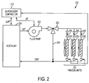
- the HVAC system includes heat pump 201.
- the heat pump 201 may be any suitable heat pump configured to exchange heat with an energy reservoir, for example, an external air source or water source.
- the system 200 further includes fluid pump 202 in fluid communication with the heat pump 201.
- the heat pump 201 provides a working fluid at a configured LWT to the fluid pump 202 for distribution throughout the system 200.
- the distribution is facilitated with three-way valve 203, which is arranged in fluid communication with both the fluid pump 202 and the heat pump 201.
- the system 200 includes a plurality of local fan-coil units 220 in fluid communication with the three-way valve 203 and the heat pump 201.
- Each fan-coil unit of the plurality of fan-coil units 220 includes at least a fluid valve 204 and a fan-coil heat exchanger 205.
- the system 200 includes supervisory controller 210 in signal communication with the heat pump 201, the fluid pump 202, and each fan-coil unit of the plurality of fan-coil units 220.
- Each fan-coil unit of the plurality of fan-coil units is arranged to provide conditioned air or fluid to a conditioned space.
- each fan-coil unit of the plurality of fan-coil units is configured to provide feedback information associated with a respective valve's position and conditioned space's return air temperature (RAT) to the supervisory controller 210.
- RAT conditioned space's return air temperature
- the supervisory controller 210 is configured to process information received from each fan-coil unit to determine an appropriate ⁇ LWT and ⁇ p. Further, the supervisory controller may be embodied as a processing apparatus, computer processor, or any other programmable processing device configured to perform method of HVAC system control as described herein, including processing of the ⁇ LWT and ⁇ p values.
- the ⁇ LWT and ⁇ p values are provided to the heat pump 201 and the fluid pump 202, or are added to default values and provided to the heat pump 201 and fluid pump 202.
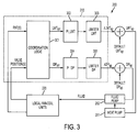
- control logic associated with the supervisory controller 210 and the HVAC system 200 is illustrated in more detail.
- the controller 210 includes coordination logic 301 configured to process RAT and valve position information from local fan-coil units 220.
- the RAT and valve position information is processed to determine if a LWT and/or DP error exists, or more clearly, if an adjustment to the LWT of the heat pump and/or the DP of the fluid pump is desirable.
- valve position and/or RAT taken across the fan-coil units 220 exceed upper or lower bounds of associated DP and LWT dead-bands, an error or other suitable signal is provided to proportional integral derivative (PID) controllers 302 and 304.
- PID proportional integral derivative
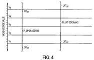
- a coordination map between a valve and fan may be pre-defined and the valve is used to control RAT. Therefore, valve opening and RAT information may be considered a load indicator for a local zone. If valve opening (e.g., position) and RAT information is taken as a weighted average across all fan-coil units, appropriate dead-bands may be determined and used to coordinate the error signals.
- a valve target set-point may be set as V 3 for the HVAC system.
- a V 1 - V 4 dead-band may be appropriate for PI_DP controller 304 and a V 2 - V 5 dead-band may be appropriate for PI_LWT controller 302.
- the PI_DP controller 304 and the PI_LWT controller 302 may receive associated error signals DP err and LWT err .
- V 1 - V 5 it should be understood that any appropriate values may be equally suitable according to any HVAC system implementation.
- the PID controllers 302 and 304 process the error signals to determine an appropriate or desirable change in LWT and/or DP settings for the HVAC system 200.
- the change in LWT and/or DP settings may be limited by associated limiters 303 and 305 to maximum/minimum values and combined with default set-points to create new set-points for the HVAC system 200.
- the new set-points are subsequently provided to the heat pump 201 and fluid pump 202.
- limiters 303 and 305 may be omitted with appropriately limited values being provided directly from controllers 302 and 304.
- DP sp 100 kPa
- DP sp will be floating within 100- ⁇ ⁇ 100 kPa based on different loads.
- the method 500 may be processed by the supervisory controller 210 according to the schematic control scheme illustrated in FIGS. 3-4 .
- the method 500 includes monitoring RAT and valve information from the fan-coil units 220, at block 501.
- the method 500 further includes determining a weighted value for each fan-coil unit based upon the RAT and valve information at block 502.
- the weighted values may be determined according to Table 1, provided below: Table 1:
- the method 500 includes calculating a weighted valve average for the fan-coil units based upon the weighted values at block 503.
- the weighted valve average value may be determined according to Table 2, provided below:
- the supervisory controller may actually consider comfort information such that enough cooling/heating capacity is provided.
- a new LWT and/or DP set-points are determined at block 505. Thereafter, the new set-points are provided to the heat pump 201 and fluid pump 202 at block 506, and the RAT and valve information are monitored again at block 501.
- the method 500 further monitors RAT and valve information at block 501.
- exemplary embodiments of the present invention provide HVAC systems and associated control methods which enhance energy efficiency through real-time adjustment of heat pump and fluid pump set-points.
- LWT and DP set-points are adjusted based on an HVAC system's load.
- energy savings are increased in partial loads, which consist of majority of operational time of HVAC systems.
- any other suitable variables in a HVAC system may be monitored to determine new set-points.
- other adjustable variables including mass flow, air flow, or any other suitable set-point may be equally applicable to exemplary embodiments.
Landscapes
- Engineering & Computer Science (AREA)
- Mechanical Engineering (AREA)
- General Engineering & Computer Science (AREA)
- Chemical & Material Sciences (AREA)
- Combustion & Propulsion (AREA)
- Physics & Mathematics (AREA)
- Signal Processing (AREA)
- Fuzzy Systems (AREA)
- Mathematical Physics (AREA)
- Thermal Sciences (AREA)
- General Physics & Mathematics (AREA)
- Automation & Control Theory (AREA)
- Air Conditioning Control Device (AREA)
- Other Air-Conditioning Systems (AREA)
Claims (12)
- System, umfassend:eine Wärmepumpe (201), wobei die Wärmepumpe (201) dazu konfiguriert ist, eine Temperatur eines Arbeitsfluids, das aus der Wärmepumpe austritt (LWT), an einen Austrittsfluidtemperatursollwert anzupassen;eine Fluidpumpe (202) in Fluidverbindung mit der Wärmepumpe (201) durch das Arbeitsfluid, wobei die Fluidpumpe (202) dazu konfiguriert ist, den Druck des Arbeitsfluids an einen Fluiddrucksollwert anzupassen;eine Vielzahl von Wärmetauschern (205) in Fluidverbindung mit der Fluidpumpe (202), wobei jeder der Vielzahl von Wärmetauschern (205) ein Proportionalventil und ein Rücklufttemperaturmessinstrument beinhaltet, ausgebildet zum Überwachen der zugeordneten Rücklufttemperatur; undeine Überwachungssteuereinrichtung (210) in Signalverbindung mit jedem von der Vielzahl von Wärmetauschern (205), der Fluidpumpe (202) und der Wärmepumpe (201), wobei die Überwachungssteuereinrichtung (210) dazu konfiguriert ist, den Austrittsfluidtemperatursollwert zu variieren und den Fluiddrucksollwert auf Grundlage eines gewichteten Mittelwerts zu variieren, der über alle Ventilstellungen jedes Proportionalventils der Vielzahl von Wärmetauschern (205) ermittelt wird und über alle Rücklufttemperaturen, die der Vielzahl von Wärmetauschern (205) zugeordnet sind, ermittelt wird.
- System nach Anspruch 1, wobei der Austrittsfluidtemperatursollwert ein konfigurierbarer Vorgabewert ist und wobei die Überwachungssteuereinrichtung (210) dazu konfiguriert ist, diesen konfigurierbaren Vorgabewert zu variieren.
- System nach Anspruch 1, wobei der Fluiddrucksollwert ein konfigurierbarer Vorgabewert ist und wobei die Überwachungssteuereinrichtung (210) dazu konfiguriert ist, diesen konfigurierbaren Vorgabewert zu variieren.
- System nach Anspruch 1, wobei jeder Wärmetauscher (205) der Vielzahl von Wärmetauschern (205) eine Ventilator-Windungseinheit (220) ist.
- System nach Anspruch 4, wobei die Überwachungssteuereinrichtung (210) eine programmierbare Verarbeitungseinrichtung ist, die dazu konfiguriert ist,
eine HVAC-Systemsteuerung durchzuführen, insbesondere:Ventilstellungen jedes Proportionalventils der Vielzahl von Wärmetauschern zu überwachen;Rücklufttemperaturen, die jedem Wärmetauscher zugeordnet sind, zu überwachen; undeinen gewichteten Mittelwert über die überwachten Stellungen und die überwachten Rücklufttemperaturen zu berechnen. - System nach Anspruch 5, wobei die Überwachungssteuereinrichtung (210) ferner dazu konfiguriert ist, einen gewichteten Ventilstellungswert für jedes Proportionalventil der Vielzahl von Wärmetauschern zu bestimmen und einen gewichteten Temperaturwert für jede Rücklufttemperatur, die der Vielzahl von Wärmetauschern zugeordnet ist, zu bestimmen, wobei der gewichtete Mittelwert einen Mittelwert der gewichteten Ventilstellungswerte und der gewichteten Temperaturwerte umfasst.
- System nach Anspruch 6, wobei die Überwachungssteuereinrichtung (210) ferner dazu konfiguriert ist, zu bestimmen, ob der gewichtete Mittelwert außerhalb eines Totwertbereichs, der einer mittleren Sollventilstellung zugeordnet ist, liegt, und wenn der gewichtete Mittelwert außerhalb des Totwertbereichs liegt, einen neuen Austrittsfluidtemperatursollwert und einen neuen Fluiddrucksollwert auf Grundlage des gewichteten Mittelwerts zu bestimmen.
- Verfahren zur HVAC-Systemsteuerung, wobei das HVAC-System Folgendes umfasst:eine Wärmepumpe (201), wobei die Wärmepumpe (201) dazu konfiguriert ist, eine Temperatur eines Arbeitsfluids, das aus der Wärmepumpe austritt (LWT), an einen Austrittsfluidtemperatursollwert anzupassen;eine Fluidpumpe (202) in Fluidverbindung mit der Wärmepumpe (201) durch das Arbeitsfluid, wobei die Fluidpumpe (202) dazu konfiguriert ist, den Druck des Arbeitsfluids an einen Fluiddrucksollwert anzupassen;eine Vielzahl von Wärmetauschern (205) in Fluidverbindung mit der Fluidpumpe (202), wobei jeder der Vielzahl von Wärmetauschern (205) ein Proportionalventil und ein Rücklufttemperaturmessinstrument beinhaltet, ausgebildet zum Überwachen der zugeordneten Rücklufttemperatur; undeine Überwachungssteuereinrichtung (210) in Signalverbindung mit jedem von der Vielzahl von Wärmetauschern (205), der Fluidpumpe (202) und der Wärmepumpe (201),wobei das Verfahren Folgendes umfasst:Überwachen von Ventilstellungen der Proportionalventile, die jedem der Vielzahl von einzelnen Wärmetauschern (205) des HVAC-Systems zugeordnet sind;Überwachen von Rücklufttemperaturen, die jedem der Vielzahl einzelner Wärmetauscher (205) des HVAC-Systems zugeordnet sind;Bestimmen eines neuen Fluiddrucksollwerts und eines neuen Austrittsfluidtemperatursollwerts für das HVAC-System auf Grundlage der Überwachung; und Bereitstellen des neuen Fluiddrucksollwert und des neuen Austrittsfluidtemperatursollwerts an das HVAC-System; undBerechnen eines gewichteten Mittelwerts für die überwachten Stellungen und die überwachten Rücklufttemperaturen, wobei der neue Fluiddrucksollwert und der neue Austrittsfluidtemperatursollwert auf dem gewichteten Mittelwert basieren.
- Verfahren nach Anspruch 8, ferner umfassend:Bestimmen einer Gewichtung für jede überwachte Stellung und jede überwachte Rücklufttemperatur; undBerechnen eines gewichteten Mittelwerts für das HVAC-System für jede bestimmte Gewichtung, wobei der neue Fluiddrucksollwert und der neue Austrittsfluidtemperatursollwert auf dem gewichteten Mittelwert beruhen.
- Verfahren nach Anspruch 9, ferner umfassend Bestimmen, ob der gewichtete Mittelwert außerhalb eines Totwertbereichs, der einer mittleren Sollventilstellung für das HVAC-System zugeordnet ist, liegt, und Bereitstellen des neuen Fluiddrucksollwerts und des neuen Austrittsfluidtemperatursollwert an das HVAC-System, wenn der gewichtete Mittelwert außerhalb des Totwertbereichs liegt.
- Verfahren nach Anspruch 10, wobei der Totwertbereich ein Bereich von mittleren Ventilstellungen innerhalb eines vordefinierten akzeptablen Sollwertfehlerbereichs für das HVAC-System ist.
- Verfahren nach Anspruch 11, wobei der vordefinierte akzeptable Sollwertfehlerbereich ein Bereich der Varianz zwischen einer gewünschten Rücklufttemperatur und tatsächlicher Rücklufttemperatur ist.
Applications Claiming Priority (2)
| Application Number | Priority Date | Filing Date | Title |
|---|---|---|---|
| US201161513532P | 2011-07-29 | 2011-07-29 | |
| PCT/US2012/048274 WO2013019537A2 (en) | 2011-07-29 | 2012-07-26 | Hvac systems |
Publications (2)
| Publication Number | Publication Date |
|---|---|
| EP2737263A2 EP2737263A2 (de) | 2014-06-04 |
| EP2737263B1 true EP2737263B1 (de) | 2016-04-27 |
Family
ID=46650893
Family Applications (1)
| Application Number | Title | Priority Date | Filing Date |
|---|---|---|---|
| EP12746184.6A Not-in-force EP2737263B1 (de) | 2011-07-29 | 2012-07-26 | Hvac-systeme |
Country Status (4)
| Country | Link |
|---|---|
| US (1) | US9885489B2 (de) |
| EP (1) | EP2737263B1 (de) |
| ES (1) | ES2584409T3 (de) |
| WO (1) | WO2013019537A2 (de) |
Families Citing this family (8)
| Publication number | Priority date | Publication date | Assignee | Title |
|---|---|---|---|---|
| US9535411B2 (en) * | 2012-03-05 | 2017-01-03 | Siemens Aktiengesellschaft | Cloud enabled building automation system |
| JP5447627B1 (ja) * | 2012-09-26 | 2014-03-19 | ダイキン工業株式会社 | 熱源システム制御装置 |
| NO3076090T3 (de) * | 2015-03-30 | 2018-06-30 | ||
| US9851727B2 (en) | 2015-05-28 | 2017-12-26 | Carrier Corporation | Coordinated control of HVAC system using aggregated system demand |
| WO2017151758A1 (en) * | 2016-03-03 | 2017-09-08 | Carrier Corporation | Fluid pressure calibration in climate control system |
| CN110168460B (zh) * | 2017-01-05 | 2022-09-02 | 江森自控科技公司 | 集成式智能执行器和阀装置 |
| CN109163375B (zh) * | 2018-09-11 | 2023-09-26 | 哈尔滨顺易天翔热力技术开发有限公司 | 供热全网平衡自寻优控制系统及方法 |
| US20200309394A1 (en) * | 2019-03-26 | 2020-10-01 | Johnson Controls Technology Company | Hvac unit utilizing selectively modulated flow rates with hot gas reheat circuit |
Family Cites Families (41)
| Publication number | Priority date | Publication date | Assignee | Title |
|---|---|---|---|---|
| US4034801A (en) | 1975-04-14 | 1977-07-12 | Robert J. Sigel, Inc. | Optimum environmental control system for a building |
| US4926649A (en) | 1987-06-11 | 1990-05-22 | Martinez Jr George | Method and apparatus for saving energy in an air conditioning system |
| US4916909A (en) | 1988-12-29 | 1990-04-17 | Electric Power Research Institute | Cool storage supervisory controller |
| US5544809A (en) | 1993-12-28 | 1996-08-13 | Senercomm, Inc. | Hvac control system and method |
| US5440895A (en) | 1994-01-24 | 1995-08-15 | Copeland Corporation | Heat pump motor optimization and sensor fault detection |
| US5533352A (en) | 1994-06-14 | 1996-07-09 | Copeland Corporation | Forced air heat exchanging system with variable fan speed control |
| US5573181A (en) | 1995-01-06 | 1996-11-12 | Landis & Gyr Powers, Inc. | Global control of HVAC distribution system |
| US5628201A (en) * | 1995-04-03 | 1997-05-13 | Copeland Corporation | Heating and cooling system with variable capacity compressor |
| US5860286A (en) | 1997-06-06 | 1999-01-19 | Carrier Corporation | System monitoring refrigeration charge |
| US5963458A (en) * | 1997-07-29 | 1999-10-05 | Siemens Building Technologies, Inc. | Digital controller for a cooling and heating plant having near-optimal global set point control strategy |
| JP3137114B1 (ja) | 1999-10-06 | 2001-02-19 | 松下電器産業株式会社 | 多室形空気調和装置 |
| US6539738B2 (en) * | 2000-06-08 | 2003-04-01 | University Of Puerto Rico | Compact solar-powered air conditioning systems |
| US6536677B2 (en) * | 2000-06-08 | 2003-03-25 | University Of Puerto Rico | Automation and control of solar air conditioning systems |
| WO2002010652A1 (en) | 2000-07-28 | 2002-02-07 | Kitz Corporation | Control system with communication function and facility control system |
| US6766651B2 (en) | 2001-02-28 | 2004-07-27 | Scott Dillenback | Central media dispenser for use in HVAC system |
| US6973410B2 (en) | 2001-05-15 | 2005-12-06 | Chillergy Systems, Llc | Method and system for evaluating the efficiency of an air conditioning apparatus |
| US6666042B1 (en) * | 2002-07-01 | 2003-12-23 | American Standard International Inc. | Sequencing of variable primary flow chiller system |
| DE102004008521B3 (de) | 2004-02-20 | 2005-10-27 | Testo Ag | Verfahren und Anordnung zum Bestimmen des Wärmeanschlusswertes eines Gebäudes |
| US7036330B2 (en) | 2004-06-24 | 2006-05-02 | Carrier Corporation | Free cooling activation optimized controls |
| JP2006031113A (ja) * | 2004-07-12 | 2006-02-02 | Canon Inc | 熱交換方法及び熱交換装置、露光装置、デバイスの製造方法 |
| JP2006125789A (ja) | 2004-11-01 | 2006-05-18 | Fuji Electric Holdings Co Ltd | 冷却装置およびこれを備えた自動販売機 |
| KR100640856B1 (ko) | 2004-12-14 | 2006-11-02 | 엘지전자 주식회사 | 멀티 공기조화기의 제어방법 |
| DE102005050666A1 (de) | 2005-03-31 | 2006-10-19 | Klaus Ferl | Temperaturregelung für Thermodecke direktverdampfend |
| US8316926B2 (en) * | 2005-10-31 | 2012-11-27 | General Cybernation Group Inc. | Arrangement and method for automatically determined time constant for a control device |
| WO2008051222A1 (en) | 2006-10-23 | 2008-05-02 | Carrier Corporation | Heating, ventilation, air conditioning and refrigeration system with multi-zone monitoring and diagnostics |
| US7890215B2 (en) * | 2006-12-22 | 2011-02-15 | Duncan Scot M | Optimized control system for cooling systems |
| US7847681B2 (en) | 2007-03-23 | 2010-12-07 | Johnson Controls Technology Company | Building automation systems and methods |
| US20080264086A1 (en) * | 2007-04-25 | 2008-10-30 | Mingsheng Liu | Method for improving efficiency in heating and cooling systems |
| US20080283621A1 (en) | 2007-05-16 | 2008-11-20 | Inncom International, Inc. | Occupant controlled energy management system and method for managing energy consumption in a multi-unit building |
| TWI318283B (en) | 2007-07-06 | 2009-12-11 | Chunghwa Telecom Co Ltd | Network-based air-conditioning equipment remote monitoring and management system |
| CN101861552B (zh) | 2007-07-17 | 2014-08-20 | 约翰逊控制技术公司 | 带有执行器饱和控制的极值搜索控制 |
| TW200930955A (en) | 2008-01-15 | 2009-07-16 | Chunghwa Telecom Co Ltd | Management system for scheduling air condition apparatus |
| JP4569678B2 (ja) * | 2008-07-11 | 2010-10-27 | ダイキン工業株式会社 | 空気調和装置の起動制御装置 |
| US8326464B2 (en) | 2008-08-29 | 2012-12-04 | Trane International Inc. | Return fan control system and method |
| WO2010051198A2 (en) * | 2008-10-31 | 2010-05-06 | Carrier Corporation | Control of multiple zone refrigerant vapor compression systems |
| US8543244B2 (en) | 2008-12-19 | 2013-09-24 | Oliver Joe Keeling | Heating and cooling control methods and systems |
| DE102009007591B3 (de) | 2009-02-05 | 2011-03-10 | Hochschule für Technik und Wirtschaft Berlin. | Verfahren und Vorrichtung zur Luftkonditionierung |
| EP2302470A3 (de) | 2009-09-29 | 2014-06-11 | Honeywell International Inc. | Systeme und Verfahren zur Konfiguration eines Bauverwaltungssystems |
| US8341973B2 (en) * | 2009-12-14 | 2013-01-01 | Mingsheng Liu | Optimizer for single staged refrigeration systems |
| CN201731568U (zh) | 2010-06-29 | 2011-02-02 | 广州国灵空调有限公司 | 风机盘管 |
| JP2012154596A (ja) * | 2011-01-28 | 2012-08-16 | Azbil Corp | 空調制御装置および方法 |
-
2012
- 2012-07-26 WO PCT/US2012/048274 patent/WO2013019537A2/en not_active Ceased
- 2012-07-26 ES ES12746184.6T patent/ES2584409T3/es active Active
- 2012-07-26 US US14/235,499 patent/US9885489B2/en not_active Expired - Fee Related
- 2012-07-26 EP EP12746184.6A patent/EP2737263B1/de not_active Not-in-force
Also Published As
| Publication number | Publication date |
|---|---|
| WO2013019537A3 (en) | 2013-10-10 |
| ES2584409T3 (es) | 2016-09-27 |
| CN103717984A (zh) | 2014-04-09 |
| US9885489B2 (en) | 2018-02-06 |
| EP2737263A2 (de) | 2014-06-04 |
| WO2013019537A2 (en) | 2013-02-07 |
| US20140158783A1 (en) | 2014-06-12 |
Similar Documents
| Publication | Publication Date | Title |
|---|---|---|
| EP2737263B1 (de) | Hvac-systeme | |
| EP2981767B1 (de) | Klimasystem und verfahren zu dessen regelung | |
| US10203128B2 (en) | Cold water circulation system with control of supply of cold water based on degree of air handler surplus | |
| US20190323720A1 (en) | Method for improving operational efficiency of a cooling system through retrofitting a building with a master controller | |
| WO2008079829A2 (en) | Optimized control system for cooling systems | |
| US11543148B2 (en) | Air conditioning system and control method therof | |
| JP2013224794A (ja) | クリーンルームの空調制御方法とその装置 | |
| EP3370005B1 (de) | Klimatisierungssystem | |
| JP6221198B2 (ja) | 外調機の制御装置 | |
| EP2102568B1 (de) | Luftklimatisierungsalgorithmus für wasserterminalfreikühlung | |
| EP3098529B1 (de) | Koordinierte steuerung von hlk-systemen mittels aggregiertem systembedarf | |
| JP6024726B2 (ja) | 外調機の制御装置 | |
| JP5318446B2 (ja) | 外気取入システム | |
| JP6213781B2 (ja) | 外調機の制御方法 | |
| EP3824229B1 (de) | Kühlsystem und verfahren zur erzeugung von koordinierungskennfelder für energieeffiziente kühlwassertemperatur und kondensatorwassertemperatur in einem kühlkraftwerksystem | |
| JP5768151B2 (ja) | ヒートポンプ式空調機およびヒートポンプ式空調機の制御方法 | |
| JP4691582B2 (ja) | 空調二次ポンプの制御装置 | |
| JP5285925B2 (ja) | 空調システム | |
| EP3791115B1 (de) | Hlk-system und steuerverfahren dafür | |
| CN103717984B (zh) | Hvac系统 | |
| JP5940608B2 (ja) | 熱媒体循環システム | |
| WO2013003304A1 (en) | Coordinated flow control | |
| US11561018B2 (en) | Central plant control system with control region detection based on control envelope ray-casting | |
| EP3434425B1 (de) | Zentrales anlagensteuerungssystem basierend auf lastprognose durch ein massenspeichermodell |
Legal Events
| Date | Code | Title | Description |
|---|---|---|---|
| PUAI | Public reference made under article 153(3) epc to a published international application that has entered the european phase |
Free format text: ORIGINAL CODE: 0009012 |
|
| 17P | Request for examination filed |
Effective date: 20140203 |
|
| AK | Designated contracting states |
Kind code of ref document: A2 Designated state(s): AL AT BE BG CH CY CZ DE DK EE ES FI FR GB GR HR HU IE IS IT LI LT LU LV MC MK MT NL NO PL PT RO RS SE SI SK SM TR |
|
| DAX | Request for extension of the european patent (deleted) | ||
| 17Q | First examination report despatched |
Effective date: 20150225 |
|
| REG | Reference to a national code |
Ref country code: DE Ref legal event code: R079 Ref document number: 602012017729 Country of ref document: DE Free format text: PREVIOUS MAIN CLASS: F25B0001080000 Ipc: G05D0023190000 |
|
| RIC1 | Information provided on ipc code assigned before grant |
Ipc: G05D 23/19 20060101AFI20150901BHEP Ipc: F24D 19/10 20060101ALI20150901BHEP Ipc: F25B 41/04 20060101ALI20150901BHEP Ipc: F24F 11/00 20060101ALI20150901BHEP |
|
| GRAP | Despatch of communication of intention to grant a patent |
Free format text: ORIGINAL CODE: EPIDOSNIGR1 |
|
| INTG | Intention to grant announced |
Effective date: 20151022 |
|
| GRAS | Grant fee paid |
Free format text: ORIGINAL CODE: EPIDOSNIGR3 |
|
| GRAA | (expected) grant |
Free format text: ORIGINAL CODE: 0009210 |
|
| AK | Designated contracting states |
Kind code of ref document: B1 Designated state(s): AL AT BE BG CH CY CZ DE DK EE ES FI FR GB GR HR HU IE IS IT LI LT LU LV MC MK MT NL NO PL PT RO RS SE SI SK SM TR |
|
| REG | Reference to a national code |
Ref country code: GB Ref legal event code: FG4D |
|
| REG | Reference to a national code |
Ref country code: CH Ref legal event code: EP |
|
| REG | Reference to a national code |
Ref country code: AT Ref legal event code: REF Ref document number: 795466 Country of ref document: AT Kind code of ref document: T Effective date: 20160515 |
|
| REG | Reference to a national code |
Ref country code: IE Ref legal event code: FG4D |
|
| REG | Reference to a national code |
Ref country code: DE Ref legal event code: R096 Ref document number: 602012017729 Country of ref document: DE |
|
| REG | Reference to a national code |
Ref country code: FR Ref legal event code: PLFP Year of fee payment: 5 |
|
| REG | Reference to a national code |
Ref country code: NL Ref legal event code: FP |
|
| REG | Reference to a national code |
Ref country code: LT Ref legal event code: MG4D |
|
| REG | Reference to a national code |
Ref country code: AT Ref legal event code: MK05 Ref document number: 795466 Country of ref document: AT Kind code of ref document: T Effective date: 20160427 |
|
| REG | Reference to a national code |
Ref country code: ES Ref legal event code: FG2A Ref document number: 2584409 Country of ref document: ES Kind code of ref document: T3 Effective date: 20160927 |
|
| PG25 | Lapsed in a contracting state [announced via postgrant information from national office to epo] |
Ref country code: FI Free format text: LAPSE BECAUSE OF FAILURE TO SUBMIT A TRANSLATION OF THE DESCRIPTION OR TO PAY THE FEE WITHIN THE PRESCRIBED TIME-LIMIT Effective date: 20160427 Ref country code: PL Free format text: LAPSE BECAUSE OF FAILURE TO SUBMIT A TRANSLATION OF THE DESCRIPTION OR TO PAY THE FEE WITHIN THE PRESCRIBED TIME-LIMIT Effective date: 20160427 Ref country code: LT Free format text: LAPSE BECAUSE OF FAILURE TO SUBMIT A TRANSLATION OF THE DESCRIPTION OR TO PAY THE FEE WITHIN THE PRESCRIBED TIME-LIMIT Effective date: 20160427 Ref country code: NO Free format text: LAPSE BECAUSE OF FAILURE TO SUBMIT A TRANSLATION OF THE DESCRIPTION OR TO PAY THE FEE WITHIN THE PRESCRIBED TIME-LIMIT Effective date: 20160727 |
|
| PG25 | Lapsed in a contracting state [announced via postgrant information from national office to epo] |
Ref country code: GR Free format text: LAPSE BECAUSE OF FAILURE TO SUBMIT A TRANSLATION OF THE DESCRIPTION OR TO PAY THE FEE WITHIN THE PRESCRIBED TIME-LIMIT Effective date: 20160728 Ref country code: RS Free format text: LAPSE BECAUSE OF FAILURE TO SUBMIT A TRANSLATION OF THE DESCRIPTION OR TO PAY THE FEE WITHIN THE PRESCRIBED TIME-LIMIT Effective date: 20160427 Ref country code: LV Free format text: LAPSE BECAUSE OF FAILURE TO SUBMIT A TRANSLATION OF THE DESCRIPTION OR TO PAY THE FEE WITHIN THE PRESCRIBED TIME-LIMIT Effective date: 20160427 Ref country code: AT Free format text: LAPSE BECAUSE OF FAILURE TO SUBMIT A TRANSLATION OF THE DESCRIPTION OR TO PAY THE FEE WITHIN THE PRESCRIBED TIME-LIMIT Effective date: 20160427 Ref country code: PT Free format text: LAPSE BECAUSE OF FAILURE TO SUBMIT A TRANSLATION OF THE DESCRIPTION OR TO PAY THE FEE WITHIN THE PRESCRIBED TIME-LIMIT Effective date: 20160829 Ref country code: HR Free format text: LAPSE BECAUSE OF FAILURE TO SUBMIT A TRANSLATION OF THE DESCRIPTION OR TO PAY THE FEE WITHIN THE PRESCRIBED TIME-LIMIT Effective date: 20160427 Ref country code: SE Free format text: LAPSE BECAUSE OF FAILURE TO SUBMIT A TRANSLATION OF THE DESCRIPTION OR TO PAY THE FEE WITHIN THE PRESCRIBED TIME-LIMIT Effective date: 20160427 |
|
| PG25 | Lapsed in a contracting state [announced via postgrant information from national office to epo] |
Ref country code: IT Free format text: LAPSE BECAUSE OF FAILURE TO SUBMIT A TRANSLATION OF THE DESCRIPTION OR TO PAY THE FEE WITHIN THE PRESCRIBED TIME-LIMIT Effective date: 20160427 Ref country code: BE Free format text: LAPSE BECAUSE OF FAILURE TO SUBMIT A TRANSLATION OF THE DESCRIPTION OR TO PAY THE FEE WITHIN THE PRESCRIBED TIME-LIMIT Effective date: 20160427 |
|
| REG | Reference to a national code |
Ref country code: DE Ref legal event code: R097 Ref document number: 602012017729 Country of ref document: DE |
|
| PG25 | Lapsed in a contracting state [announced via postgrant information from national office to epo] |
Ref country code: DK Free format text: LAPSE BECAUSE OF FAILURE TO SUBMIT A TRANSLATION OF THE DESCRIPTION OR TO PAY THE FEE WITHIN THE PRESCRIBED TIME-LIMIT Effective date: 20160427 Ref country code: RO Free format text: LAPSE BECAUSE OF FAILURE TO SUBMIT A TRANSLATION OF THE DESCRIPTION OR TO PAY THE FEE WITHIN THE PRESCRIBED TIME-LIMIT Effective date: 20160427 Ref country code: EE Free format text: LAPSE BECAUSE OF FAILURE TO SUBMIT A TRANSLATION OF THE DESCRIPTION OR TO PAY THE FEE WITHIN THE PRESCRIBED TIME-LIMIT Effective date: 20160427 Ref country code: CZ Free format text: LAPSE BECAUSE OF FAILURE TO SUBMIT A TRANSLATION OF THE DESCRIPTION OR TO PAY THE FEE WITHIN THE PRESCRIBED TIME-LIMIT Effective date: 20160427 Ref country code: SK Free format text: LAPSE BECAUSE OF FAILURE TO SUBMIT A TRANSLATION OF THE DESCRIPTION OR TO PAY THE FEE WITHIN THE PRESCRIBED TIME-LIMIT Effective date: 20160427 |
|
| PG25 | Lapsed in a contracting state [announced via postgrant information from national office to epo] |
Ref country code: SM Free format text: LAPSE BECAUSE OF FAILURE TO SUBMIT A TRANSLATION OF THE DESCRIPTION OR TO PAY THE FEE WITHIN THE PRESCRIBED TIME-LIMIT Effective date: 20160427 |
|
| REG | Reference to a national code |
Ref country code: CH Ref legal event code: PL |
|
| PLBE | No opposition filed within time limit |
Free format text: ORIGINAL CODE: 0009261 |
|
| STAA | Information on the status of an ep patent application or granted ep patent |
Free format text: STATUS: NO OPPOSITION FILED WITHIN TIME LIMIT |
|
| GBPC | Gb: european patent ceased through non-payment of renewal fee |
Effective date: 20160727 |
|
| PG25 | Lapsed in a contracting state [announced via postgrant information from national office to epo] |
Ref country code: MC Free format text: LAPSE BECAUSE OF FAILURE TO SUBMIT A TRANSLATION OF THE DESCRIPTION OR TO PAY THE FEE WITHIN THE PRESCRIBED TIME-LIMIT Effective date: 20160427 |
|
| 26N | No opposition filed |
Effective date: 20170130 |
|
| PG25 | Lapsed in a contracting state [announced via postgrant information from national office to epo] |
Ref country code: CH Free format text: LAPSE BECAUSE OF NON-PAYMENT OF DUE FEES Effective date: 20160731 Ref country code: LI Free format text: LAPSE BECAUSE OF NON-PAYMENT OF DUE FEES Effective date: 20160731 |
|
| REG | Reference to a national code |
Ref country code: IE Ref legal event code: MM4A |
|
| PG25 | Lapsed in a contracting state [announced via postgrant information from national office to epo] |
Ref country code: GB Free format text: LAPSE BECAUSE OF NON-PAYMENT OF DUE FEES Effective date: 20160727 Ref country code: SI Free format text: LAPSE BECAUSE OF FAILURE TO SUBMIT A TRANSLATION OF THE DESCRIPTION OR TO PAY THE FEE WITHIN THE PRESCRIBED TIME-LIMIT Effective date: 20160427 |
|
| REG | Reference to a national code |
Ref country code: FR Ref legal event code: PLFP Year of fee payment: 6 |
|
| REG | Reference to a national code |
Ref country code: DE Ref legal event code: R082 Ref document number: 602012017729 Country of ref document: DE Representative=s name: SCHMITT-NILSON SCHRAUD WAIBEL WOHLFROM PATENTA, DE |
|
| PG25 | Lapsed in a contracting state [announced via postgrant information from national office to epo] |
Ref country code: IE Free format text: LAPSE BECAUSE OF NON-PAYMENT OF DUE FEES Effective date: 20160726 |
|
| PG25 | Lapsed in a contracting state [announced via postgrant information from national office to epo] |
Ref country code: LU Free format text: LAPSE BECAUSE OF NON-PAYMENT OF DUE FEES Effective date: 20160726 |
|
| PG25 | Lapsed in a contracting state [announced via postgrant information from national office to epo] |
Ref country code: CY Free format text: LAPSE BECAUSE OF FAILURE TO SUBMIT A TRANSLATION OF THE DESCRIPTION OR TO PAY THE FEE WITHIN THE PRESCRIBED TIME-LIMIT Effective date: 20160427 Ref country code: HU Free format text: LAPSE BECAUSE OF FAILURE TO SUBMIT A TRANSLATION OF THE DESCRIPTION OR TO PAY THE FEE WITHIN THE PRESCRIBED TIME-LIMIT; INVALID AB INITIO Effective date: 20120726 |
|
| REG | Reference to a national code |
Ref country code: FR Ref legal event code: PLFP Year of fee payment: 7 |
|
| PG25 | Lapsed in a contracting state [announced via postgrant information from national office to epo] |
Ref country code: IS Free format text: LAPSE BECAUSE OF FAILURE TO SUBMIT A TRANSLATION OF THE DESCRIPTION OR TO PAY THE FEE WITHIN THE PRESCRIBED TIME-LIMIT Effective date: 20160427 Ref country code: MT Free format text: LAPSE BECAUSE OF NON-PAYMENT OF DUE FEES Effective date: 20160731 Ref country code: MK Free format text: LAPSE BECAUSE OF FAILURE TO SUBMIT A TRANSLATION OF THE DESCRIPTION OR TO PAY THE FEE WITHIN THE PRESCRIBED TIME-LIMIT Effective date: 20160427 |
|
| PG25 | Lapsed in a contracting state [announced via postgrant information from national office to epo] |
Ref country code: BG Free format text: LAPSE BECAUSE OF FAILURE TO SUBMIT A TRANSLATION OF THE DESCRIPTION OR TO PAY THE FEE WITHIN THE PRESCRIBED TIME-LIMIT Effective date: 20160427 |
|
| PG25 | Lapsed in a contracting state [announced via postgrant information from national office to epo] |
Ref country code: TR Free format text: LAPSE BECAUSE OF FAILURE TO SUBMIT A TRANSLATION OF THE DESCRIPTION OR TO PAY THE FEE WITHIN THE PRESCRIBED TIME-LIMIT Effective date: 20160427 Ref country code: AL Free format text: LAPSE BECAUSE OF FAILURE TO SUBMIT A TRANSLATION OF THE DESCRIPTION OR TO PAY THE FEE WITHIN THE PRESCRIBED TIME-LIMIT Effective date: 20160427 |
|
| PGFP | Annual fee paid to national office [announced via postgrant information from national office to epo] |
Ref country code: NL Payment date: 20190625 Year of fee payment: 8 |
|
| PGFP | Annual fee paid to national office [announced via postgrant information from national office to epo] |
Ref country code: FR Payment date: 20190621 Year of fee payment: 8 |
|
| PGFP | Annual fee paid to national office [announced via postgrant information from national office to epo] |
Ref country code: DE Payment date: 20190620 Year of fee payment: 8 Ref country code: ES Payment date: 20190801 Year of fee payment: 8 |
|
| REG | Reference to a national code |
Ref country code: DE Ref legal event code: R119 Ref document number: 602012017729 Country of ref document: DE |
|
| REG | Reference to a national code |
Ref country code: NL Ref legal event code: MM Effective date: 20200801 |
|
| PG25 | Lapsed in a contracting state [announced via postgrant information from national office to epo] |
Ref country code: NL Free format text: LAPSE BECAUSE OF NON-PAYMENT OF DUE FEES Effective date: 20200801 Ref country code: FR Free format text: LAPSE BECAUSE OF NON-PAYMENT OF DUE FEES Effective date: 20200731 |
|
| PG25 | Lapsed in a contracting state [announced via postgrant information from national office to epo] |
Ref country code: DE Free format text: LAPSE BECAUSE OF NON-PAYMENT OF DUE FEES Effective date: 20210202 |
|
| REG | Reference to a national code |
Ref country code: ES Ref legal event code: FD2A Effective date: 20211230 |
|
| PG25 | Lapsed in a contracting state [announced via postgrant information from national office to epo] |
Ref country code: ES Free format text: LAPSE BECAUSE OF NON-PAYMENT OF DUE FEES Effective date: 20200727 |