EP2737631B1 - Procédé et système d'architecture radio de système sans fil basé sur la technologie d'évolution à long terme - Google Patents
Procédé et système d'architecture radio de système sans fil basé sur la technologie d'évolution à long terme Download PDFInfo
- Publication number
- EP2737631B1 EP2737631B1 EP12735630.1A EP12735630A EP2737631B1 EP 2737631 B1 EP2737631 B1 EP 2737631B1 EP 12735630 A EP12735630 A EP 12735630A EP 2737631 B1 EP2737631 B1 EP 2737631B1
- Authority
- EP
- European Patent Office
- Prior art keywords
- radio
- signals
- power
- output ports
- power amplifiers
- Prior art date
- Legal status (The legal status is an assumption and is not a legal conclusion. Google has not performed a legal analysis and makes no representation as to the accuracy of the status listed.)
- Not-in-force
Links
Images


Classifications
-
- H—ELECTRICITY
- H04—ELECTRIC COMMUNICATION TECHNIQUE
- H04B—TRANSMISSION
- H04B1/00—Details of transmission systems, not covered by a single one of groups H04B3/00 - H04B13/00; Details of transmission systems not characterised by the medium used for transmission
- H04B1/02—Transmitters
- H04B1/04—Circuits
- H04B1/0475—Circuits with means for limiting noise, interference or distortion
-
- H—ELECTRICITY
- H03—ELECTRONIC CIRCUITRY
- H03F—AMPLIFIERS
- H03F1/00—Details of amplifiers with only discharge tubes, only semiconductor devices or only unspecified devices as amplifying elements
- H03F1/34—Negative-feedback-circuit arrangements with or without positive feedback
-
- H—ELECTRICITY
- H03—ELECTRONIC CIRCUITRY
- H03F—AMPLIFIERS
- H03F3/00—Amplifiers with only discharge tubes or only semiconductor devices as amplifying elements
- H03F3/20—Power amplifiers, e.g. Class B amplifiers, Class C amplifiers
- H03F3/24—Power amplifiers, e.g. Class B amplifiers, Class C amplifiers of transmitter output stages
-
- H—ELECTRICITY
- H03—ELECTRONIC CIRCUITRY
- H03F—AMPLIFIERS
- H03F3/00—Amplifiers with only discharge tubes or only semiconductor devices as amplifying elements
- H03F3/68—Combinations of amplifiers, e.g. multi-channel amplifiers for stereophonics
-
- H—ELECTRICITY
- H04—ELECTRIC COMMUNICATION TECHNIQUE
- H04B—TRANSMISSION
- H04B1/00—Details of transmission systems, not covered by a single one of groups H04B3/00 - H04B13/00; Details of transmission systems not characterised by the medium used for transmission
- H04B1/02—Transmitters
- H04B1/04—Circuits
- H04B2001/0408—Circuits with power amplifiers
- H04B2001/0433—Circuits with power amplifiers with linearisation using feedback
Definitions
- Document EP 2 178 204 A1 may be construed to disclose a radio transmission system comprising a plurality of power amplifiers (PAs); a plurality of Volterra Engine (VE) linearizers corresponding to the PAs; a plurality of feedback loops corresponding to the PAs; at least one digital hybrid matrix (DHM) coupled to the VE linearizers; and an analog hybrid matrix (AHM) coupled to the PAs, wherein the feedback loops are connected to the AHM and the VE linearizers but not to the PAs to reduce the number of feedback loops.
- PAs power amplifiers
- VE Volterra Engine
- DLM digital hybrid matrix
- AHM analog hybrid matrix
- FIG. 1 a diagram of a wireless communication system constructed in accordance with principles of the present invention and denoted generally as "10."
- the wireless communication system 10 includes a base station 12 having a radio 14 that employs power pooling circuitry 16, feedback circuit 17, and direct up converters 18 in the transmitter, as explained below.
- the radio 14 may also employ direct down conversion in the receiver.
- An exemplary wireless transceiver (radio) 14 constructed in accordance with principles of the present invention is described with reference to FIG. 2 .
- Data is received at the radio from a data source at a distribution network device 24, and data is transmitted from the radio to a location external to the radio via the distribution network device 24.
- the distribution network device 24 provides an interface from the radio to the radio controlling equipment. More particularly, the distribution network device 24 distributes multiple single channel samples to the digital transmit processors 26 and from the digital receivers 28.
- FIG. 2 also shows a plurality of digital transmit processors 26 for processing each of a plurality of channels.
- Each digital transmit processor 26 performs baseband processing of the single carriers including, automatic level control (ALC), filtering (pulse shaping) equalization, gain/phase shifting and power measurements.
- a digital transmit processor 26 changes the sample rate of a single carrier signal to a rate that allows frequency shifting and summation into a multi-carrier signal. More particularly, the digital transmit processor 26 shifts the single carrier in preparation of summation into a multi-carrier signal.
- the digital transmit processor 26 adds the input up-sampled frequency-shifted carriers to create one multi-carrier signal per path. Power control can also be performed by the digital transmit processor 26.
- the outputs of the DBM 30 are fed to a direct up-converter (DUC) 36.
- the direct up-converter 36 processes the signals from the outputs of the DBM 30 to drive a digital analog converter (not shown in FIG. 2 ) to provide a desired radio frequency (RF) analog signal.
- Direct up-conversion is implemented by up-sampling by a factor of N and filtering about a carrier frequency of the desired RF signal.
- Linearizers (not shown in FIG. 2 ) receive feedback signals from the power amplifiers 32 to linearize the outputs of the power amplifiers 32.
- the digital signals are coupled to the digital receivers 28.
- the digital receivers 28 receive the multi-carrier digital signals and frequency-shift them to baseband.
- the digital receivers 28 perform filtering, equalization, gain and phase shifting, and power control functions. Note that in some embodiments, the receiver components 44, 46 and 28 may be replaced by direct digital down-conversion components which filter the received signals and down-sample them to baseband.
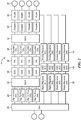
- FIG. 3 is a more detailed block diagram of a transmitter 21 constructed in accordance with principles of the present invention.
- the transmitter 21 includes a digital processing transmit section 31, a plurality of power amplifiers 32, an analog processing transmit section 33, and radio output ports 20.
- the digital processing transmit section 31 includes a digital matrix 30, linearizers 48, direct up-converters 36, and digital to analog converters 50.
- the analog processing transmit section 33 includes couplers 38, an analog matrix 34 and couplers 40.
- the digital matrix 30 distributes a plurality of carrier signals to the plurality of power amplifier channels after adjusting a gain and phase of each carrier signal based on feedback signals from couplers 40 such that the outputs of the plurality of power amplifiers are channeled by the analog matrix 34 to a selected one or more radio output ports 20.
- the outputs of the combiners 52 are coupled to the couplers 38.
- a sample of the power from each combiner 52 is coupled to an RF multiplexer 54 and fed back to the linearizers 48 via an analog to digital converter 56 and a direct down converter 58.
- Most of the power from combiners 52 are coupled by couplers 38 to the analog matrix 34, which channels the amplified up-sampled adjusted carrier signals to a selected one or more radio output ports 20.
- Samples of the outputs of the analog matrix 34 are coupled by couplers 40 to the RF multiplexer 54 to the digital matrix 30.
- the portion of the outputs of the analog matrix coupled by the couplers 40 are used as feedback signals that control gain and phase adjustments of the carrier signals received by the digital matrix 30.
- the feedback circuit 17 includes the couplers 40, the RF multiplexer 54, the ADC 56 and the DDC 58.
- the remainder of the power from the analog matrix 34 is coupled by couplers 40 to the duplexers 42, which in turn, couple the power to the output ports 20.
- the output ports 20 are coupled to antennas (not shown) which are oriented to transmit to one or more geographical sectors serviced by the radio.
- a single RF multiplexer 54 may be provided for the feedback signals from the couplers 38 and the couplers 40.
- one multiplexer is provided for the feedback from the couplers 38 and another multiplexer is provided for the feedback from the couplers 40.
- one embodiment is a radio for wireless communication that uses power pooling and direct up-conversion to reduce the number of radios required support all potential frequencies and modulation arrangements within a market space.
- the radio includes one or more radio output ports 20 fed by a plurality of power amplifiers 32.
- the radio includes a digital processing transmit section 31 and an analog processing transmit section 33.
- the digital processing transmit section 31 includes a digital matrix 30 that distributes a plurality of carrier signals to the plurality of power amplifiers 32.
- the digital matrix 30 adjusts a gain and phase of each carrier signal based on first feedback signals such that the outputs of the plurality of power amplifiers 32 are channeled to a selected one or more radio output ports 20.
- the digital processing section 31 also includes a plurality of direct up-converters 36 that are each in communication directly or indirectly with a corresponding one of the plurality of power amplifiers 32. Each direct up-converter up-samples the gain and phase adjusted carrier signals from the digital matrix 30.
- the plurality of power amplifiers 32 amplify the up-sampled adjusted carrier signals.
- the analog processing transmit section 33 includes an analog matrix 34, such as an analog Butler matrix, which channels the amplified up-sampled adjusted carrier signals to the selected one or more radio output ports 20.
- a plurality of couplers 40 couple first feedback signals from the analog matrix 34 to the digital matrix 30 to enable the digital matrix to adjust the gain and phase of each carrier signals, such that the outputs of the plurality of power amplifiers 32 are channeled to the selected one or more radio output ports 20.
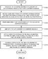
- a plurality of data signals modulated onto carrier signals are received at a digital matrix (step S102). Within the digital matrix, the gain and phase of each carrier signal is adjusted based on feedback signals so that the outputs of power amplifiers are directed to one or more radio output ports (step S104). Direct up-conversion of the adjusted carrier signals is performed (step S106). The up-converted carrier signals are amplified by a plurality of power amplifiers (step S108). The amplified signals are applied to an analog matrix which distributes the amplified signals to the selected one or more radio output ports (step S110). Outputs of the analog matrix are coupled as feedback signals to enable the digital matrix to adjust gain and phase of the carrier signals to cause distribution of the amplified signals to the selected one or more radio output ports (step S112).
- the gain and phase adjusted carrier signals are up-converted by a direct up-conversion module.
- the up-converted adjusted carrier signals are amplified in power amplifiers.
- the amplified up-converted adjusted carrier signals are applied to an analog matrix, which channels the signals to the selected one or more radio output ports. Outputs of the analog matrix are also used to provide feedback signals at the digital matrix to enable the digital matrix to adjust the phase and gain of the carrier signals as needed to cause the signals to be channeled to the selected one or more radio output ports.
- the present invention can be realized in hardware, or a combination of hardware and software. Any kind of computing system, or other apparatus adapted for carrying out the methods described herein, is suited to perform the functions described herein.
- a typical combination of hardware and software could be a specialized computer system, e.g., a router, having one or more processing elements and a computer program stored on a storage medium that, when loaded and executed, controls the computer system such that it carries out the methods described herein.
- the present invention can also be embedded in a computer program product, which comprises all the features enabling the implementation of the methods described herein, and which, when loaded in a computing system is able to carry out these methods.
- Storage medium refers to any volatile or nonvolatile storage device.
Landscapes
- Engineering & Computer Science (AREA)
- Power Engineering (AREA)
- Computer Networks & Wireless Communication (AREA)
- Signal Processing (AREA)
- Transmitters (AREA)
- Amplifiers (AREA)
Claims (16)
- Radio (14) de communication sans fil, la radio comprenant :une pluralité de ports de sortie radio (20) ;une pluralité d'amplificateurs de puissance (32) ;une circuiterie de regroupement de puissance, la circuiterie de regroupement de puissance étant configurée pour :- ajuster des gains et des phases d'une pluralité de signaux de porteuse sur la base de premiers signaux de rétroaction ; et- diriger sélectivement des signaux de sortie des amplificateurs de puissance (32) vers N ports de sortie radio sélectionnés, de sorte que 1/N d'une sortie totale de tous les amplificateurs de puissance (32) soit allouée à chacun des N ports de sortie radio sélectionnés (20), N étant inférieur à un nombre total de la pluralité de ports de sortie radio (20), les premiers signaux de rétroaction étant basés sur les signaux de sortie dirigés sélectivement ;une pluralité de convertisseurs élévateurs directs (36), chacun de la pluralité de convertisseurs élévateurs directs étant configuré pour communiquer avec un amplificateur de puissance correspondant (32), chacun de la pluralité de convertisseurs élévateurs directs étant configuré pour traiter les signaux de porteuse ajustés, le traitement comprenant le suréchantillonnage des signaux de porteuse ajustés ; etla pluralité d'amplificateurs de puissance (32) étant configurés pour :- amplifier les signaux de porteuse suréchantillonnés ajustés, et- délivrer les signaux de porteuse suréchantillonnés ajustés amplifiés pour une transmission en utilisant l'au moins un port de sortie radio sélectionné (20).
- Radio selon la revendication 1, dans laquelle :
la circuiterie de regroupement de puissance comprend :une matrice numérique (30), la matrice numérique étant configurée pour :- distribuer la pluralité de signaux de porteuse à la pluralité d'amplificateurs de puissance (32) par l'intermédiaire des convertisseurs élévateurs directs (36), et- ajuster un gain et une phase de chaque signal de porteuse sur la base des premiers signaux de rétroaction de sorte que des sorties de la pluralité d'amplificateurs de puissance soient canalisées vers les N ports de sortie radio sélectionnés ; et/oudans laquelle la circuiterie de regroupement de puissance comprend :
une matrice analogique (34), la matrice analogique comportant une pluralité d'entrées configurées pour recevoir les signaux de porteuse ajustés suréchantillonnés amplifiés en provenance d'un amplificateur de puissance correspondant (32) et comportant une pluralité de sorties configurées pour canaliser les signaux de porteuse ajustés suréchantillonnés amplifiés vers les N ports de sortie radio sélectionnés (20). - Radio selon la revendication 1, comprenant en outre des premiers coupleurs (34) configurés pour coupler les premiers signaux de rétroaction des signaux de sortie dirigés sélectivement à la circuiterie de regroupement de puissance.
- Radio selon la revendication 3, comprenant en outre un multiplexeur RF (54), le multiplexeur RF étant configuré pour multiplexer les premiers signaux de rétroaction de la pluralité de premiers coupleurs (38) .
- Radio selon la revendication 1, dans laquelle la circuiterie de regroupement de puissance comprend une pluralité de dispositifs de linéarité (48), chaque dispositif de linéarité étant :électriquement couplé à au moins un convertisseur élévateur direct (36) ; etconfiguré pour fournir une correction de linéarité à un amplificateur de puissance (32) correspondant au convertisseur élévateur direct (36).
- Radio selon la revendication 5,
dans laquelle chacun de la pluralité d'amplificateurs de puissance (32) comporte une sortie d'amplificateur de puissance et les dispositifs de linéarité (48) sont configurés pour recevoir des deuxièmes signaux de rétroaction en provenance d'une sortie d'amplificateur de puissance correspondante ; et facultativement
comprenant en outre une pluralité de deuxièmes coupleurs (40), la pluralité de deuxièmes coupleurs étant couplés aux amplificateurs de puissance et configurés pour fournir les deuxièmes signaux de rétroaction ; et facultativement
dans laquelle la radio est configurée pour convertir les premiers signaux de rétroaction multiplexés en signaux numériques (56) avant le couplage des premiers signaux de rétroaction à la circuiterie de regroupement de puissance. - Radio selon la revendication 1,
comprenant en outre une pluralité de convertisseurs numérique-analogique, DAC, (50), chaque DAC étant couplé à un amplificateur de puissance correspondant (32), la pluralité de DAC (50) étant configurés pour fonctionner à un taux d'échantillonnage qui est basé sur la plus grande fréquence d'un signal de porteuse ; ou
dans laquelle la radio est configurée pour sélectionner les N ports de sortie radio sélectionnés sur la base d'une puissance souhaitée par port de sortie radio (20). - Radio selon la revendication 1, comprenant en outre une pluralité d'antennes, chaque antenne étant couplée à un port de sortie radio correspondant (20).
- Radio selon la revendication 8, dans laquelle chaque antenne est dirigée vers un secteur géographique différent desservi par la radio (21).
- Radio selon la revendication 1, toutes les caractéristiques des revendications 2, 3 et 8 étant destinées à être utilisées dans un système de communication sans fil, la radio comprenant :un émetteur, l'émetteur incluant :- la matrice numérique (30) ;- la pluralité de convertisseurs élévateurs directs (36) ;- la pluralité d'amplificateurs de puissance (32) ;- la matrice analogique (34) ;- la pluralité de coupleurs (40) ; et- la pluralité d'antennes, chaque antenne étant couplée à un port de sortie radio (20) ; etun récepteur (44, 46, 28), le récepteur recevant des signaux en provenance des antennes au cours d'une réception.
- Radio selon la revendication 10, dans laquelle :le récepteur (44, 46, 28) comprend une unité de conversion abaissement directe, l'unité de conversion abaissement directe étant configurée pour effectuer la conversion abaissement des signaux reçus par l'intermédiaire d'un échantillonnage direct des signaux reçus ; oules convertisseurs élévateurs directs (36) incluent des convertisseurs numérique-analogique ayant des taux d'échantillonnage fixes sélectionnés pour effectuer la conversion élévation des signaux de porteuse ajustés dans une pluralité de bandes de fréquences distinctes.
- Radio selon la revendication 10, dans laquelle l'un sélectionné des ports de sortie (20) reçoit une puissance en provenance d'une pluralité des amplificateurs de puissance (32).
- Radio selon la revendication 12, dans laquelle la puissance provenant de la pluralité d'amplificateurs de puissance (32) est combinée par la matrice analogique (34).
- Radio selon la revendication 1, dans laquelle la circuiterie de regroupement de puissance est en outre configurée pour ajuster des gains et des phases d'une pluralité de signaux de porteuse sur la base de premiers signaux de rétroaction, de sorte que des sorties de la pluralité d'amplificateurs de puissance soient insérées de manière cohérente uniquement aux N ports sélectionnés de la pluralité de ports de sortie radio et effectuent un brouillage destructif aux ports de sortie radio restants.
- Procédé de traitement de multiples signaux dans un émetteur d'une station de base de communication sans fil, l'émetteur comportant une pluralité d'amplificateurs de puissance (32) et une pluralité de ports de sortie radio (20), le procédé comprenant :la réception (S102), à une matrice numérique (30), d'une pluralité de signaux de porteuse portant des données ;la sélection de N ports de sortie radio, N étant inférieur à un nombre total de la pluralité de ports de sortie radio (20) ;l'ajustement (S104) d'un gain et d'une phase des signaux de porteuse dans la matrice numérique (30) et la distribution des signaux de porteuse ajustés à la pluralité d'amplificateurs de puissance (32), l'ajustement étant basé sur des premiers signaux de rétroaction de sorte que des sorties des amplificateurs de puissance soient canalisées vers les N ports de sortie radio sélectionnés (20), afin que 1/N d'une puissance de sortie totale de tous les amplificateurs de puissance (32) soit allouée à chacun des N ports de sortie radio sélectionnés (20) ;l'exécution (S106) d'une conversion élévation directe des signaux de porteuse ajustés ;l'amplification (S108) des signaux de porteuse ajustés et convertis par conversion élévation dans les amplificateurs de puissance (32) ;l'application (S110) des signaux de porteuse ajustés, convertis par conversion élévation, et amplifiés à une matrice analogique (34), la matrice analogique canalisant les signaux appliqués vers l'au moins un port de sortie radio sélectionné (20) ; etle couplage (S112) de sorties de la matrice analogique (34) pour produire les premiers signaux de rétroaction à la matrice numérique (30) afin de permettre à la matrice numérique d'ajuster la phase et le gain des signaux de porteuse.
- Support de mémorisation lisible par ordinateur mémorisant un programme qui, lorsqu'il est chargé et exécuté, commande à un système informatique d'effectuer toutes les étapes du procédé selon la revendication 15.
Applications Claiming Priority (2)
| Application Number | Priority Date | Filing Date | Title |
|---|---|---|---|
| US13/194,508 US8750210B2 (en) | 2011-07-29 | 2011-07-29 | Wireless long term evolution radio architecture system and method |
| PCT/IB2012/052925 WO2013017965A1 (fr) | 2011-07-29 | 2012-06-08 | Procédé et système d'architecture radio de système sans fil basé sur la technologie d'évolution à long terme |
Publications (2)
| Publication Number | Publication Date |
|---|---|
| EP2737631A1 EP2737631A1 (fr) | 2014-06-04 |
| EP2737631B1 true EP2737631B1 (fr) | 2019-03-06 |
Family
ID=46514715
Family Applications (1)
| Application Number | Title | Priority Date | Filing Date |
|---|---|---|---|
| EP12735630.1A Not-in-force EP2737631B1 (fr) | 2011-07-29 | 2012-06-08 | Procédé et système d'architecture radio de système sans fil basé sur la technologie d'évolution à long terme |
Country Status (4)
| Country | Link |
|---|---|
| US (1) | US8750210B2 (fr) |
| EP (1) | EP2737631B1 (fr) |
| MX (1) | MX2014001120A (fr) |
| WO (1) | WO2013017965A1 (fr) |
Families Citing this family (5)
| Publication number | Priority date | Publication date | Assignee | Title |
|---|---|---|---|---|
| US8750174B2 (en) * | 2012-03-30 | 2014-06-10 | Broadcom Corporation | Dual carrier separation |
| US9197327B2 (en) * | 2012-09-04 | 2015-11-24 | Cisco Technology, Inc. | Optical communication transmitter system |
| US20150318611A1 (en) * | 2014-05-02 | 2015-11-05 | Parkervision, Inc. | Antenna array for communication system |
| KR102755934B1 (ko) | 2016-10-04 | 2025-01-17 | 삼성전자 주식회사 | 무선 통신 장치 및 그 제어 방법 |
| US11039850B2 (en) | 2018-02-28 | 2021-06-22 | Gi Supply | Endoscopic tool with suction for facilitating injection of a fluid into a submucosal layer of tissue |
Family Cites Families (17)
| Publication number | Priority date | Publication date | Assignee | Title |
|---|---|---|---|---|
| US5574967A (en) * | 1994-01-11 | 1996-11-12 | Ericsson Ge Mobile Communications, Inc. | Waste energy control and management in power amplifiers |
| US5955920A (en) * | 1997-07-29 | 1999-09-21 | Metawave Communications Corporation | Signal feed matrix LPA reduction system and method |
| US6006111A (en) * | 1997-10-08 | 1999-12-21 | Nortel Networks Corporation | Self-balancing matrix amplifier |
| US5966048A (en) * | 1997-11-25 | 1999-10-12 | Hughes Electronics Corporation | Low IMD amplification method and apparatus |
| US6381212B1 (en) * | 1998-06-17 | 2002-04-30 | Radio Frequency Systems, Inc. | Power sharing amplifier system for amplifying multiple input signals with shared power amplifiers |
| US6243038B1 (en) * | 1998-12-17 | 2001-06-05 | Metawave Communications Corporation | System and method providing amplification of narrow band signals with multi-channel amplifiers |
| KR100703337B1 (ko) | 2002-07-13 | 2007-04-03 | 삼성전자주식회사 | 이동통신 시스템에서 적응 방식의 전력 풀링 장치 및 방법 |
| US7206355B2 (en) | 2002-12-02 | 2007-04-17 | Nortel Networks Limited | Digitally convertible radio |
| US7248656B2 (en) | 2002-12-02 | 2007-07-24 | Nortel Networks Limited | Digital convertible radio SNR optimization |
| AU2002360071A1 (en) * | 2002-12-20 | 2004-07-14 | Telefonaktiebolaget Lm Ericsson (Publ) | Peak power limitation in an amplifier pooling scenario |
| US7606322B2 (en) * | 2004-10-07 | 2009-10-20 | Microelectronics Technology Inc. | Digital pre-distortion technique using nonlinear filters |
| US7558541B2 (en) | 2004-12-01 | 2009-07-07 | The Boeing Company | Amplifier gain and phase stabilizer |
| WO2007134615A1 (fr) | 2006-05-19 | 2007-11-29 | Telefonaktiebolaget L M Ericsson (Publ) | Dispositif doté d'amplificateurs de puissance partagés pour être utilisé dans un système de télécommunications sans fil |
| US7961045B2 (en) | 2007-03-30 | 2011-06-14 | Nortel Networks Limited | Amplifier pre-distortion systems and methods |
| US8213880B2 (en) | 2008-10-15 | 2012-07-03 | Rockstar Bidco, LP | Minimum feedback radio architecture with digitally configurable adaptive linearization |
| US8553807B2 (en) | 2008-10-20 | 2013-10-08 | Apple Inc. | Methods and systems for programmable digital up-conversion |
| US20120328050A1 (en) * | 2011-06-21 | 2012-12-27 | Telefonaktiebolaget L M Ericsson (Publ) | Centralized adaptor architecture for power amplifier linearizations in advanced wireless communication systems |
-
2011
- 2011-07-29 US US13/194,508 patent/US8750210B2/en active Active
-
2012
- 2012-06-08 MX MX2014001120A patent/MX2014001120A/es active IP Right Grant
- 2012-06-08 EP EP12735630.1A patent/EP2737631B1/fr not_active Not-in-force
- 2012-06-08 WO PCT/IB2012/052925 patent/WO2013017965A1/fr not_active Ceased
Non-Patent Citations (1)
| Title |
|---|
| None * |
Also Published As
| Publication number | Publication date |
|---|---|
| US20130028178A1 (en) | 2013-01-31 |
| MX2014001120A (es) | 2014-02-27 |
| EP2737631A1 (fr) | 2014-06-04 |
| WO2013017965A1 (fr) | 2013-02-07 |
| US8750210B2 (en) | 2014-06-10 |
Similar Documents
| Publication | Publication Date | Title |
|---|---|---|
| US8665845B2 (en) | Communication system, network element and method for antenna array beam-forming | |
| US9923524B2 (en) | Digital pre-distortion for multi-antenna systems | |
| US9461590B2 (en) | Envelope tracking in connection with simultaneous transmission in one or more frequency bands | |
| CN102082752B (zh) | 一种数字预失真处理方法及设备 | |
| US9106453B2 (en) | Remote radio head unit system with wideband power amplifier and method | |
| US9048797B2 (en) | High efficiency, remotely reconfigurable remote radio head unit system and method for wireless communications | |
| US8923370B2 (en) | Radio communication apparatus method | |
| US12224837B2 (en) | Systems and methods for reconfigurable repeaters for wireless telecommunications | |
| KR20100042233A (ko) | 디지털적으로 구성가능한 적응 선형화를 갖는 최소 피드백 무선 구조 | |
| KR20130103732A (ko) | 무선 네트워크에서 운용되는 다중대역 라디오 장치 및 방법 | |
| EP2737631B1 (fr) | Procédé et système d'architecture radio de système sans fil basé sur la technologie d'évolution à long terme | |
| US20070110177A1 (en) | RF power distribution in the frequency domain | |
| US10637525B2 (en) | Wireless device and wireless communication method | |
| EP3804252B1 (fr) | Dispositif for hybrid transmitter | |
| US20090233644A1 (en) | Multiple carrier radio systems and methods employing polar active antenna elements | |
| JP4624517B2 (ja) | アクティブアンテナを適用した基地局 | |
| JP2000228646A (ja) | 携帯移動端末および送信装置 | |
| JP2005348116A (ja) | 無線通信装置 | |
| EP1890386A1 (fr) | Module frontal numérique pour émetteur multistandard et station de base multistandard | |
| WO2026024445A1 (fr) | Circuit amplificateur de puissance à plage dynamique | |
| KR20050077855A (ko) | 무선 통신 시스템용 전력증폭기의 채널별 송신 전력제어방법 | |
| KR20050034923A (ko) | 전력 증폭 선형화 제어 시스템 | |
| HK1230352A1 (en) | System for improving isolation between transmitters and receivers | |
| HK1230352A (en) | System for improving isolation between transmitters and receivers |
Legal Events
| Date | Code | Title | Description |
|---|---|---|---|
| PUAI | Public reference made under article 153(3) epc to a published international application that has entered the european phase |
Free format text: ORIGINAL CODE: 0009012 |
|
| 17P | Request for examination filed |
Effective date: 20140123 |
|
| AK | Designated contracting states |
Kind code of ref document: A1 Designated state(s): AL AT BE BG CH CY CZ DE DK EE ES FI FR GB GR HR HU IE IS IT LI LT LU LV MC MK MT NL NO PL PT RO RS SE SI SK SM TR |
|
| DAX | Request for extension of the european patent (deleted) | ||
| GRAP | Despatch of communication of intention to grant a patent |
Free format text: ORIGINAL CODE: EPIDOSNIGR1 |
|
| STAA | Information on the status of an ep patent application or granted ep patent |
Free format text: STATUS: GRANT OF PATENT IS INTENDED |
|
| INTG | Intention to grant announced |
Effective date: 20181026 |
|
| GRAS | Grant fee paid |
Free format text: ORIGINAL CODE: EPIDOSNIGR3 |
|
| GRAA | (expected) grant |
Free format text: ORIGINAL CODE: 0009210 |
|
| STAA | Information on the status of an ep patent application or granted ep patent |
Free format text: STATUS: THE PATENT HAS BEEN GRANTED |
|
| AK | Designated contracting states |
Kind code of ref document: B1 Designated state(s): AL AT BE BG CH CY CZ DE DK EE ES FI FR GB GR HR HU IE IS IT LI LT LU LV MC MK MT NL NO PL PT RO RS SE SI SK SM TR |
|
| REG | Reference to a national code |
Ref country code: GB Ref legal event code: FG4D |
|
| REG | Reference to a national code |
Ref country code: CH Ref legal event code: EP Ref country code: AT Ref legal event code: REF Ref document number: 1105945 Country of ref document: AT Kind code of ref document: T Effective date: 20190315 |
|
| REG | Reference to a national code |
Ref country code: DE Ref legal event code: R096 Ref document number: 602012057443 Country of ref document: DE |
|
| REG | Reference to a national code |
Ref country code: IE Ref legal event code: FG4D |
|
| REG | Reference to a national code |
Ref country code: NL Ref legal event code: MP Effective date: 20190306 |
|
| REG | Reference to a national code |
Ref country code: LT Ref legal event code: MG4D |
|
| PG25 | Lapsed in a contracting state [announced via postgrant information from national office to epo] |
Ref country code: SE Free format text: LAPSE BECAUSE OF FAILURE TO SUBMIT A TRANSLATION OF THE DESCRIPTION OR TO PAY THE FEE WITHIN THE PRESCRIBED TIME-LIMIT Effective date: 20190306 Ref country code: FI Free format text: LAPSE BECAUSE OF FAILURE TO SUBMIT A TRANSLATION OF THE DESCRIPTION OR TO PAY THE FEE WITHIN THE PRESCRIBED TIME-LIMIT Effective date: 20190306 Ref country code: NO Free format text: LAPSE BECAUSE OF FAILURE TO SUBMIT A TRANSLATION OF THE DESCRIPTION OR TO PAY THE FEE WITHIN THE PRESCRIBED TIME-LIMIT Effective date: 20190606 Ref country code: LT Free format text: LAPSE BECAUSE OF FAILURE TO SUBMIT A TRANSLATION OF THE DESCRIPTION OR TO PAY THE FEE WITHIN THE PRESCRIBED TIME-LIMIT Effective date: 20190306 |
|
| PG25 | Lapsed in a contracting state [announced via postgrant information from national office to epo] |
Ref country code: BG Free format text: LAPSE BECAUSE OF FAILURE TO SUBMIT A TRANSLATION OF THE DESCRIPTION OR TO PAY THE FEE WITHIN THE PRESCRIBED TIME-LIMIT Effective date: 20190606 Ref country code: GR Free format text: LAPSE BECAUSE OF FAILURE TO SUBMIT A TRANSLATION OF THE DESCRIPTION OR TO PAY THE FEE WITHIN THE PRESCRIBED TIME-LIMIT Effective date: 20190607 Ref country code: HR Free format text: LAPSE BECAUSE OF FAILURE TO SUBMIT A TRANSLATION OF THE DESCRIPTION OR TO PAY THE FEE WITHIN THE PRESCRIBED TIME-LIMIT Effective date: 20190306 Ref country code: LV Free format text: LAPSE BECAUSE OF FAILURE TO SUBMIT A TRANSLATION OF THE DESCRIPTION OR TO PAY THE FEE WITHIN THE PRESCRIBED TIME-LIMIT Effective date: 20190306 Ref country code: NL Free format text: LAPSE BECAUSE OF FAILURE TO SUBMIT A TRANSLATION OF THE DESCRIPTION OR TO PAY THE FEE WITHIN THE PRESCRIBED TIME-LIMIT Effective date: 20190306 Ref country code: RS Free format text: LAPSE BECAUSE OF FAILURE TO SUBMIT A TRANSLATION OF THE DESCRIPTION OR TO PAY THE FEE WITHIN THE PRESCRIBED TIME-LIMIT Effective date: 20190306 |
|
| REG | Reference to a national code |
Ref country code: AT Ref legal event code: MK05 Ref document number: 1105945 Country of ref document: AT Kind code of ref document: T Effective date: 20190306 |
|
| PG25 | Lapsed in a contracting state [announced via postgrant information from national office to epo] |
Ref country code: IT Free format text: LAPSE BECAUSE OF FAILURE TO SUBMIT A TRANSLATION OF THE DESCRIPTION OR TO PAY THE FEE WITHIN THE PRESCRIBED TIME-LIMIT Effective date: 20190306 Ref country code: ES Free format text: LAPSE BECAUSE OF FAILURE TO SUBMIT A TRANSLATION OF THE DESCRIPTION OR TO PAY THE FEE WITHIN THE PRESCRIBED TIME-LIMIT Effective date: 20190306 Ref country code: RO Free format text: LAPSE BECAUSE OF FAILURE TO SUBMIT A TRANSLATION OF THE DESCRIPTION OR TO PAY THE FEE WITHIN THE PRESCRIBED TIME-LIMIT Effective date: 20190306 Ref country code: CZ Free format text: LAPSE BECAUSE OF FAILURE TO SUBMIT A TRANSLATION OF THE DESCRIPTION OR TO PAY THE FEE WITHIN THE PRESCRIBED TIME-LIMIT Effective date: 20190306 Ref country code: EE Free format text: LAPSE BECAUSE OF FAILURE TO SUBMIT A TRANSLATION OF THE DESCRIPTION OR TO PAY THE FEE WITHIN THE PRESCRIBED TIME-LIMIT Effective date: 20190306 Ref country code: AL Free format text: LAPSE BECAUSE OF FAILURE TO SUBMIT A TRANSLATION OF THE DESCRIPTION OR TO PAY THE FEE WITHIN THE PRESCRIBED TIME-LIMIT Effective date: 20190306 Ref country code: PT Free format text: LAPSE BECAUSE OF FAILURE TO SUBMIT A TRANSLATION OF THE DESCRIPTION OR TO PAY THE FEE WITHIN THE PRESCRIBED TIME-LIMIT Effective date: 20190706 Ref country code: SK Free format text: LAPSE BECAUSE OF FAILURE TO SUBMIT A TRANSLATION OF THE DESCRIPTION OR TO PAY THE FEE WITHIN THE PRESCRIBED TIME-LIMIT Effective date: 20190306 |
|
| PG25 | Lapsed in a contracting state [announced via postgrant information from national office to epo] |
Ref country code: PL Free format text: LAPSE BECAUSE OF FAILURE TO SUBMIT A TRANSLATION OF THE DESCRIPTION OR TO PAY THE FEE WITHIN THE PRESCRIBED TIME-LIMIT Effective date: 20190306 Ref country code: SM Free format text: LAPSE BECAUSE OF FAILURE TO SUBMIT A TRANSLATION OF THE DESCRIPTION OR TO PAY THE FEE WITHIN THE PRESCRIBED TIME-LIMIT Effective date: 20190306 |
|
| REG | Reference to a national code |
Ref country code: DE Ref legal event code: R097 Ref document number: 602012057443 Country of ref document: DE |
|
| PG25 | Lapsed in a contracting state [announced via postgrant information from national office to epo] |
Ref country code: AT Free format text: LAPSE BECAUSE OF FAILURE TO SUBMIT A TRANSLATION OF THE DESCRIPTION OR TO PAY THE FEE WITHIN THE PRESCRIBED TIME-LIMIT Effective date: 20190306 Ref country code: IS Free format text: LAPSE BECAUSE OF FAILURE TO SUBMIT A TRANSLATION OF THE DESCRIPTION OR TO PAY THE FEE WITHIN THE PRESCRIBED TIME-LIMIT Effective date: 20190706 |
|
| PLBE | No opposition filed within time limit |
Free format text: ORIGINAL CODE: 0009261 |
|
| STAA | Information on the status of an ep patent application or granted ep patent |
Free format text: STATUS: NO OPPOSITION FILED WITHIN TIME LIMIT |
|
| PG25 | Lapsed in a contracting state [announced via postgrant information from national office to epo] |
Ref country code: MC Free format text: LAPSE BECAUSE OF FAILURE TO SUBMIT A TRANSLATION OF THE DESCRIPTION OR TO PAY THE FEE WITHIN THE PRESCRIBED TIME-LIMIT Effective date: 20190306 Ref country code: DK Free format text: LAPSE BECAUSE OF FAILURE TO SUBMIT A TRANSLATION OF THE DESCRIPTION OR TO PAY THE FEE WITHIN THE PRESCRIBED TIME-LIMIT Effective date: 20190306 |
|
| REG | Reference to a national code |
Ref country code: CH Ref legal event code: PL |
|
| 26N | No opposition filed |
Effective date: 20191209 |
|
| PG25 | Lapsed in a contracting state [announced via postgrant information from national office to epo] |
Ref country code: SI Free format text: LAPSE BECAUSE OF FAILURE TO SUBMIT A TRANSLATION OF THE DESCRIPTION OR TO PAY THE FEE WITHIN THE PRESCRIBED TIME-LIMIT Effective date: 20190306 |
|
| REG | Reference to a national code |
Ref country code: BE Ref legal event code: MM Effective date: 20190630 |
|
| PG25 | Lapsed in a contracting state [announced via postgrant information from national office to epo] |
Ref country code: TR Free format text: LAPSE BECAUSE OF FAILURE TO SUBMIT A TRANSLATION OF THE DESCRIPTION OR TO PAY THE FEE WITHIN THE PRESCRIBED TIME-LIMIT Effective date: 20190306 |
|
| PG25 | Lapsed in a contracting state [announced via postgrant information from national office to epo] |
Ref country code: IE Free format text: LAPSE BECAUSE OF NON-PAYMENT OF DUE FEES Effective date: 20190608 |
|
| PG25 | Lapsed in a contracting state [announced via postgrant information from national office to epo] |
Ref country code: CH Free format text: LAPSE BECAUSE OF NON-PAYMENT OF DUE FEES Effective date: 20190630 Ref country code: LI Free format text: LAPSE BECAUSE OF NON-PAYMENT OF DUE FEES Effective date: 20190630 Ref country code: LU Free format text: LAPSE BECAUSE OF NON-PAYMENT OF DUE FEES Effective date: 20190608 Ref country code: BE Free format text: LAPSE BECAUSE OF NON-PAYMENT OF DUE FEES Effective date: 20190630 |
|
| PG25 | Lapsed in a contracting state [announced via postgrant information from national office to epo] |
Ref country code: CY Free format text: LAPSE BECAUSE OF FAILURE TO SUBMIT A TRANSLATION OF THE DESCRIPTION OR TO PAY THE FEE WITHIN THE PRESCRIBED TIME-LIMIT Effective date: 20190306 |
|
| PG25 | Lapsed in a contracting state [announced via postgrant information from national office to epo] |
Ref country code: HU Free format text: LAPSE BECAUSE OF FAILURE TO SUBMIT A TRANSLATION OF THE DESCRIPTION OR TO PAY THE FEE WITHIN THE PRESCRIBED TIME-LIMIT; INVALID AB INITIO Effective date: 20120608 Ref country code: MT Free format text: LAPSE BECAUSE OF FAILURE TO SUBMIT A TRANSLATION OF THE DESCRIPTION OR TO PAY THE FEE WITHIN THE PRESCRIBED TIME-LIMIT Effective date: 20190306 |
|
| PG25 | Lapsed in a contracting state [announced via postgrant information from national office to epo] |
Ref country code: MK Free format text: LAPSE BECAUSE OF FAILURE TO SUBMIT A TRANSLATION OF THE DESCRIPTION OR TO PAY THE FEE WITHIN THE PRESCRIBED TIME-LIMIT Effective date: 20190306 |
|
| PGFP | Annual fee paid to national office [announced via postgrant information from national office to epo] |
Ref country code: FR Payment date: 20220627 Year of fee payment: 11 |
|
| PGFP | Annual fee paid to national office [announced via postgrant information from national office to epo] |
Ref country code: DE Payment date: 20220629 Year of fee payment: 11 |
|
| REG | Reference to a national code |
Ref country code: DE Ref legal event code: R119 Ref document number: 602012057443 Country of ref document: DE |
|
| PG25 | Lapsed in a contracting state [announced via postgrant information from national office to epo] |
Ref country code: DE Free format text: LAPSE BECAUSE OF NON-PAYMENT OF DUE FEES Effective date: 20240103 |
|
| PG25 | Lapsed in a contracting state [announced via postgrant information from national office to epo] |
Ref country code: FR Free format text: LAPSE BECAUSE OF NON-PAYMENT OF DUE FEES Effective date: 20230630 |
|
| PGFP | Annual fee paid to national office [announced via postgrant information from national office to epo] |
Ref country code: GB Payment date: 20240627 Year of fee payment: 13 |
|
| GBPC | Gb: european patent ceased through non-payment of renewal fee |
Effective date: 20250608 |
|
| PG25 | Lapsed in a contracting state [announced via postgrant information from national office to epo] |
Ref country code: GB Free format text: LAPSE BECAUSE OF NON-PAYMENT OF DUE FEES Effective date: 20250608 |