EP2738089A2 - Trappe de train d'atterrissage silencieuse - Google Patents
Trappe de train d'atterrissage silencieuse Download PDFInfo
- Publication number
- EP2738089A2 EP2738089A2 EP20130190893 EP13190893A EP2738089A2 EP 2738089 A2 EP2738089 A2 EP 2738089A2 EP 20130190893 EP20130190893 EP 20130190893 EP 13190893 A EP13190893 A EP 13190893A EP 2738089 A2 EP2738089 A2 EP 2738089A2
- Authority
- EP
- European Patent Office
- Prior art keywords
- landing gear
- door
- flap
- leading edge
- wake
- Prior art date
- Legal status (The legal status is an assumption and is not a legal conclusion. Google has not performed a legal analysis and makes no representation as to the accuracy of the status listed.)
- Granted
Links
Images


Classifications
-
- B—PERFORMING OPERATIONS; TRANSPORTING
- B64—AIRCRAFT; AVIATION; COSMONAUTICS
- B64C—AEROPLANES; HELICOPTERS
- B64C25/00—Alighting gear
- B64C25/001—Devices not provided for in the groups B64C25/02 - B64C25/68
-
- B—PERFORMING OPERATIONS; TRANSPORTING
- B64—AIRCRAFT; AVIATION; COSMONAUTICS
- B64C—AEROPLANES; HELICOPTERS
- B64C23/00—Influencing air flow over aircraft surfaces, not otherwise provided for
- B64C23/005—Influencing air flow over aircraft surfaces, not otherwise provided for by other means not covered by groups B64C23/02 - B64C23/08, e.g. by electric charges, magnetic panels, piezoelectric elements, static charges or ultrasounds
-
- B—PERFORMING OPERATIONS; TRANSPORTING
- B64—AIRCRAFT; AVIATION; COSMONAUTICS
- B64C—AEROPLANES; HELICOPTERS
- B64C25/00—Alighting gear
- B64C25/02—Undercarriages
- B64C25/08—Undercarriages non-fixed, e.g. jettisonable
- B64C25/10—Undercarriages non-fixed, e.g. jettisonable retractable, foldable, or the like
- B64C25/16—Fairings movable in conjunction with undercarriage elements
-
- B—PERFORMING OPERATIONS; TRANSPORTING
- B64—AIRCRAFT; AVIATION; COSMONAUTICS
- B64C—AEROPLANES; HELICOPTERS
- B64C25/00—Alighting gear
- B64C25/001—Devices not provided for in the groups B64C25/02 - B64C25/68
- B64C2025/003—Means for reducing landing gear noise, or turbulent flow around it, e.g. landing gear doors used as deflectors
Definitions
- Embodiments of the present disclosure relate generally to landing gear structures. More particularly, embodiments of the present disclosure relate to landing gear doors.
- a quiet (low noise or reduced noise) landing gear door and methods are presented.
- a landing gear door comprising a trailing edge and a leading edge deploys to a landing gear door deployed position.
- a door flap hinged to the trailing edge deflects toward a landing gear strut to a door flap deployed position in response to deployment of the landing gear door.
- a leading edge section deflects toward a landing gear strut to a leading edge deployed position in response to deployment of the landing gear door.
- embodiments of the disclosure provide a quiet landing gear door that reduces noise generated by interaction of a landing gear wake with an aerodynamic surface.
- a quiet landing gear door comprises a landing gear door, a door flap, and a leading edge section.
- the landing gear door comprises a trailing edge and a leading edge and deploys to a landing gear door deployed position.
- the door flap comprises the trailing edge and is hinged to the landing gear door. The door flap deflects toward a landing gear strut to a door flap deployed position in response to deployment of the landing gear door.
- the leading edge section comprises the leading edge and is coupled to the door flap. The leading edge section deflects toward the landing gear strut to a leading edge deployed position.
- a method for reducing landing gear wake-wing flap interaction noise deploys a landing gear door comprising a trailing edge and a leading edge. The method further deflects toward a landing gear strut a leading edge section comprising the leading edge and coupled to the landing gear door. The method also deflects toward the landing gear strut a door flap comprising the trailing edge and hinged to the landing gear door. The method further reduces a flow velocity on a pressure side of the landing gear door due deflecting the bullnose and the door flap.
- a method for configuring a quiet landing gear door configures a landing gear door to deploy to a landing gear deployed position.
- the method couples a leading edge section and a door flap to the landing gear door.
- the method then configures the leading edge section and the door flap to deflect toward a landing gear strut in the landing gear deployed position to reduce a local flow speed near the landing gear strut and minimize a wake impinging on a pressure side of an aerodynamic surface of an aircraft such that a landing gear noise and a landing gear wake-aerodynamic surface interaction noise are reduced.
- a quiet landing gear door comprising: a landing gear door comprising a trailing edge and a leading edge and operable to deploy to a landing gear door deployed position; a door flap comprising the trailing edge and hinged to the landing gear door and operable to deflect toward a landing gear strut to a door flap deployed position in response to deployment of the landing gear door; and a leading edge section comprising the leading edge and coupled to landing gear door and operable to deflect toward the landing gear strut to a leading edge section deployed position in response to deployment of the landing gear door.
- leading edge section in the leading edge section deployed position and the door flap in the door flap deployed position reduces a flow velocity on a pressure side of the landing gear door reducing a landing gear wake-wing flap interaction noise.
- a nominal door flap deflection angle is below 30 degrees.
- the leading edge section in the leading edge section deployed position and the door flap in the door flap deployed position reduce the landing gear wake-wing flap interaction noise generated by a landing gear wake-wing flap interaction.
- the leading edge section in the leading edge deployed position and the door flap in the door flap deployed position reduce a landing gear wake impinging on a pressure side of a wing flap reducing the landing gear wake-wing flap interaction and the landing gear wake-wing flap interaction noise.
- reducing the landing gear wake-wing flap interaction increases effectiveness of the wing flap.
- reducing the landing gear wake-wing flap interaction reduces a risk of unexpected buffet of the wing flap.
- the door flap is located at a percent of a chord plane of the landing gear door.
- the landing gear door is coupled to a landing gear structure of an aircraft.
- a method for reducing landing gear noise comprising: deploying a landing gear door comprising a trailing edge and a leading edge; deflecting toward a strut a leading edge section comprising the leading edge and coupled to the landing gear door; deflecting toward the strut a door flap comprising the trailing edge and hinged to the landing gear door; and reducing a flow velocity on a pressure side of the landing gear door due to deflecting the leading edge section and the door flap.
- the method further comprises reducing a landing gear strut noise of the landing gear strut in response to reducing the flow velocity.
- the method further comprises reducing a landing gear wake-wing flap interaction noise generated by an interaction of a landing gear wake with a wing flap.
- the door flap is located at a percent of a chord plane of the landing gear door.
- the method further comprises reducing a landing gear wake impinging on a pressure side of a wing flap in response to reducing the flow velocity.
- the method further comprises reducing an interaction of the landing gear wake with the wing flap in response to reducing the flow velocity.
- the method further comprises increasing a wing flap effectiveness of the wing flap in response to reducing the interaction of the landing gear wake with the wing flap.
- the method further comprises reducing a risk of unexpected buffet of the wing flap in response to reducing the interaction of the landing gear wake with the wing flap.
- a method for configuring a quiet landing gear door comprising: configuring a landing gear door to deploy to a landing gear deployed position; coupling a leading edge section to the landing gear door; hinging a door flap to the landing gear door; and configure the leading edge section and the door flap to deflect toward a landing gear strut in the landing gear deployed position to reduce a local flow speed near the landing gear strut and minimize a wake impinging on a pressure side of an aerodynamic surface of an aircraft such that a landing gear noise and a landing gear wake-aerodynamic surface interaction noise are reduced.
- the method further comprises locating the door flap at a percent chord plane of the landing gear door.
- the method further comprises coupling the landing gear door to a main landing gear structure of the aircraft.
- Embodiments of the disclosure may be described herein in terms of functional and/or logical block components and various processing steps. It should be appreciated that such block components may be realized by any number of hardware, software, and/or firmware components configured to perform the specified functions. For the sake of brevity, conventional techniques and components related to aircraft landing gear door, aircraft landing gear door operation, and other functional aspects of systems described herein (and the individual operating components of the systems) may not be described in detail herein. In addition, those skilled in the art will appreciate that embodiments of the present disclosure may be practiced in conjunction with a variety of hardware and software, and that the embodiments described herein are merely example embodiments of the disclosure.
- embodiments of the disclosure may be described in the context of an exemplary aircraft manufacturing and service method 100 (method 100) as shown in Figure 1 and an aircraft 200 as shown in Figure 2 .
- the method 100 may comprise specification and design 104 of the aircraft 200, and material procurement 106.
- component and subassembly manufacturing 108 process 108 and integration of system 110 (system integration 110) of the aircraft 200 takes place.
- system integration 110 system integration 110
- the aircraft 200 may go through certification and delivery 112 in order to be placed in service 114.
- routine maintenance and service 116 which may also comprise modification, reconfiguration, refurbishment, and so on).
- a system integrator may comprise, for example but without limitation, any number of aircraft manufacturers and major-system subcontractors
- a third party may comprise, for example but without limitation, any number of vendors, subcontractors, and suppliers
- an operator may comprise, for example but without limitation, an airline, leasing company, military entity, service organization; and the like.
- the aircraft 200 produced by the method 100 may comprise an airframe 218 with a plurality of systems 220 and an interior 222.
- high-level systems of the systems 220 comprise one or more of a propulsion system 224, an electrical system 226, a hydraulic system 228, an environmental system 230, and a quiet (low noise) landing gear door 232. Any number of other systems may also be included.
- quiet may mean, for example but without limitation, low noise, reduced noise, or attenuated noise.
- Apparatus and methods embodied herein may be employed during any one or more of the stages of the method 100.
- components or subassemblies corresponding to production of the process 108 may be fabricated or manufactured in a manner similar to components or subassemblies produced while the aircraft 200 is in service.
- one or more apparatus embodiments, method embodiments, or a combination thereof may be utilized during production stages of the process 108 and the system integration 110, for example, by substantially expediting assembly of or reducing the cost of an aircraft 200.
- one or more of apparatus embodiments, method embodiments, or a combination thereof may be utilized while the aircraft 200 is in service, for example and without limitation, to maintenance and service 116.
- Figure 3 is an illustration of an exemplary perspective view 300 of a portion of an aircraft 200 showing a main landing gear structure 302 comprising a landing gear door 304 coupled thereto according to an embodiment of the disclosure.
- the landing gear door 304 may be coupled to an aircraft such as the aircraft 200 and may comprise a leading edge section 306, and a door flap 308.
- the landing gear door 304 comprises a trailing edge 310 and a leading edge 312 and is configured to deploy to a main landing gear door deployed position 314 as shown in Figure 3 .
- the landing gear door 304 may be coupled to the landing gear structure 302 of the aircraft 200.
- the door flap 308 comprises the trailing edge 310 and is hinged to the landing gear door 304 via a trailing edge hinge line 316.
- the door flap 308 is configured to deflect in a direction 330 toward a landing gear strut 322 to a door flap deployed position 502 (e.g., as shown in Figure 5 ) in response to deployment of the landing gear door 304.
- the door flap 308 may be located, for example but without limitation, at about 50 percent to about 60 percent of a chord plane 332 of the landing gear door 304, or other location on the chord plane 332 suitable for operation of the landing gear door 304.
- the door flap 308 may also be coupled to the landing gear door 304 via a shape memory alloy (SMA) material that can deflect in response to a temperature change, or via other coupling means that can position the door flap 308 at a deflected position when the landing gear door 304 is deployed.
- SMA shape memory alloy
- the leading edge section 306 comprises the leading edge 312 and is coupled to the landing gear door 304.
- the leading edge section 306 is configured to deflect in the direction 330 toward the landing gear strut 322 to a leading edge deployed position 504 (e.g., as shown in Figure 5 ) in response to deployment of the landing gear door 304.
- the leading edge section 306 may comprise, for example but without limitation, a bullnose fixedly coupled to the landing gear door 304, a drooped leading edge hinged to the landing gear door 304 via a leading edge hinge line 318, a drooped leading edge coupled to the landing gear door 304 via a shape memory alloy (SMA) material that can deflect in response to a temperature change, or other leading edge section that can be positioned at a deflected position when the landing gear door 304 is deployed.
- SMA shape memory alloy
- Reducing the landing gear wake-wing flap interaction increases effectiveness of the wing flap 328 by reducing a strength of the landing gear wake 402 from the landing gear door 304 impinging on the pressure side 326 of the wing flap 328. Additionally, reducing the landing gear wake-wing flap interaction reduces a risk of unexpected buffet of the wing flap 328.
- Figure 4 is an illustration of an exemplary section view of an existing landing gear door 408 showing the landing gear wake 402 that can impinge on fluid dynamic surfaces such as on the pressure side 326 of the wing flap 328.
- the landing gear wake 402 interacts with fluid dynamic surfaces such as on the wing flap 328 and may generate a landing gear wake-wing flap interaction noise.
- the fluid dynamic surfaces may comprise, for example but without limitation, aerodynamic surfaces such as a flap, a spoiler, an aileron, or other fluid dynamic surfaces cable of moving through a fluid such as air and/or water.
- Figure 5 is an illustration of an exemplary section view of the door flap 308 in the door flap deployed position 502 and the leading edge section 306 in a leading edge deployed position 504 according to an embodiment of the disclosure.
- Deflecting the door flap 308 and the leading edge section 306 reduces a local flow velocity 508 on a pressure side 506 of the door flap 308 near the landing gear strut 322 and the landing gear braces 324.
- the pressure side 506 of the door flap 308 forms at least a part of a pressure side of the landing gear door 304. Reducing the local flow velocity 508 or local speed of the local flow velocity 508 near the landing gear strut 322 minimizes the landing gear wake 402 impinging on the pressure side 326 of an aerodynamic surface such as the wing flap 328 of the aircraft 200.
- the landing gear wake 402 ( Figures 4 and 5 ) impinging on the pressure side 326 of the wing flap 328 is reduced, thereby reducing landing gear wake-wing flap interaction noise generated by interaction of the landing gear wake 402 from the landing gear strut 322 and the landing gear braces 324 with the wing flap 328. Reducing the local flow velocity also reduces a landing gear strut noise of the landing gear strut 322.
- landing gear noise generally increases in proportion to (Mach) 5
- a small reduction in the local flow velocity 508 can have a significant impact on landing gear door noise and landing gear wake-aerodynamic surface interaction noise.
- the landing gear door wake-wing flap interaction noise and landing gear noise may be reduced by, for example, about 2 dB to about 5 dB, which for gear dominated airframe noise can be significant.
- Figures 6-12 are illustrations of section views showing a free stream flow 602 over the landing gear door 304 (main landing gear door 304) at, without limitation, 8 degrees angle of incidence at various door flap deflection angles 702 according to an embodiment of the disclosure.
- strength of the landing gear wake 402 reduces as the door flap deflection angles 702 increase from, for example, about zero to about 30 degrees.
- the landing gear wake 402 may grow at higher door flap deflection angles 702 (e.g., > 30 degrees), indicating an example nominal door flap deflection angles 702 may be, for example, below 30 degrees.
- Figure 13 is an illustration of a graph 1300 showing a wake deficit 1302 of the landing gear wake 402 at various door flap deflection angles 702.
- the wake deficit 1302 is measured with the landing gear door 304 at, without limitation, 8 degrees angle of incidence, the free stream flow 602 at, without limitation, Mach 0.17 and Reynolds number (RE) of 1265400 according to an embodiment of the disclosure.
- the graph 1300 shows a non-dimensional distance Y from the landing gear door 304 (e.g., normalized by a chord length of the landing gear door 304) vs. a non-dimensional velocity magnitude.
- the wake deficit 1302 shows that the door flap 308 at the door flap deflection angles 702 of, for example, 12 degrees and 14 degrees generates minimum momentum loss in the landing gear wake 402 as shown by curves 1304 and 1306 respectively.
- Figure 14 is an illustration of a graph 1400 showing a lift coefficient C L of the landing gear door 304 vs. door flap deflection angles 702 of the door flap 308 in degrees according to an embodiment of the disclosure.
- the graph 1400 illustrates that beyond about 15 degrees of door flap deflection angle 702 the lift coefficient C L flattens and there is substantially no more additional circulation and hence substantially no substantial velocity reduction can be obtained around the landing gear strut 322.
- FIG 15 is an illustration of a graph 1500 showing a landing gear wake-wing flap interaction noise reduction due to deploying the landing gear door 304 according to an embodiment of the disclosure compared to a landing gear wake-wing flap interaction noise generated when using an existing main landing gear door.
- a curve 1502 shows sound pressure level (SPL) in dB vs. frequency in Hertz (Hz) for noise generated when the landing gear door 304 is in the landing gear door deployed position 314 with the door flap 308 and the leading edge section 306 deflected toward the landing gear strut in the direction 330.
- a curve 1504 shows SPL in dB vs. frequency in Hz for noise generated without deploying the landing gear door 304.
- the curve 1502 shows the landing gear wake-wing flap interaction noise is reduced by about 3-5 dB in the landing gear door deployed position 314.
- FIG 16 is an illustration of a block diagram of a landing gear door system 1600 (system 1600) according to an embodiment of the disclosure.
- the system 1600 may have functions, material, and structures that are similar to the embodiments shown in Figures 3 , 5 , and 6-12 . Therefore, common features, functions, and elements may not be redundantly described here.
- the system 1600 may comprise a vehicle 200 such as the aircraft 200, a fluid dynamic surface such as the wing flap 328 coupled to the aircraft 200, the landing gear structure 302 coupled to the aircraft 200 and the landing gear door 304.
- the leading edge section 306 is coupled to the landing gear door 304 and the door flap 308 may be hinged to the landing gear door 304.
- An actuator 1602 is coupled to the landing gear door 304.
- the actuator 1602 is configured to deploy the landing gear door 304 in the landing gear door deployed position 314, the leading edge section 306 in the leading edge deployed position 504 and the door flap 308 in the door flap deployed position 502 to reduce landing gear wake 402 ( Figures 4 and 5 ) impinging on the pressure side 326 of the wing flap 328, thereby reducing landing gear wake-wing flap interaction noise generated by interaction of the landing gear wake 402 from the landing gear strut 322 and the landing gear braces 324 with the wing flap 328.
- the actuator 1602 may deflect the door flap 308 at various door flap deflection angles 702 as explained above in the context of discussion of Figure 7 .
- the actuator 1602 may comprise, for example but without limitation, a linear hydraulic actuator, a ball screw actuator, or other actuator.
- the controller 1606 may be implemented as, for example but without limitation, a part of an aircraft system, a centralized aircraft processor, a subsystem computing module comprising hardware and/or software devoted to the system 1600, or other processor.
- the controller 1606 is configured to control the actuation motors 1604 to actuate the landing gear door 304 via the actuator 1602 to the landing gear door deployed position 314, the leading edge section 306 to the leading edge section deployed position 504 and the door flap 308 to the door flap deployed position 502 via the actuator 1602 according to various operation conditions.
- the operation conditions may comprise, for example but without limitation, flight conditions, ground operations, or other condition.
- the flight conditions may comprise, for example but without limitation, landing, or other flight condition.
- the ground operations may comprise, for example but without limitation, air breaking after landing, taxing, parking, or other ground operation.
- the controller 1606 may be located remotely from the actuation motors 1604, or may be coupled to the actuation motors 1604. In one embodiment, the controller 1606 may be placed in a cockpit of the aircraft 200.
- the controller 1606 may comprise a processor module 1608 comprising processing logic that is configured to carry out the functions, techniques, and processing tasks associated with the operation of the system 1600.
- the processing logic is configured to support the system 1600 described herein.
- the processor module 1608 may direct the actuation motors 1604 to deflect the leading edge section 306 and the door flap 308 via the actuator 1602.
- the processor module 1608 may be implemented, or realized, with a general purpose processor, a content addressable memory, a digital signal processor, an application specific integrated circuit, a field programmable gate array, any suitable programmable logic device, discrete gate or transistor logic, discrete hardware components, or any combination thereof, designed to perform the functions described herein.
- a processor may be realized as a microprocessor, a controller, a microcontroller, a state machine, or the like.
- a processor may also be implemented as a combination of computing devices comprising hardware and/or software, e.g., a combination of a digital signal processor and a microprocessor, a plurality of microprocessors, one or more microprocessors in conjunction with a digital signal processor core, or any other such configuration.
- the memory module 1610 may comprise a data storage area with memory formatted to support the operation of the system 1600.
- the memory module 1610 is configured to store, maintain, and provide data as needed to support the functionality of the system 1600.
- the memory module 1610 may store flight configuration data, actuation signal(s) for activation of the actuation motors 1604, the door flap deflection angles 702 of the door flap 308, or other data.
- the memory module 1610 may comprise, for example but without limitation, a non-volatile storage device (e.g., non-volatile semiconductor memory, hard disk device, optical disk device, and the like), a random access storage device (for example, SRAM, DRAM), or any other form of storage medium known in the art.
- a non-volatile storage device e.g., non-volatile semiconductor memory, hard disk device, optical disk device, and the like
- a random access storage device for example, SRAM, DRAM
- the memory module 1610 may be coupled to the processor module 1608 and configured to store, for example but without limitation, a database, and the like. Additionally, the memory module 1610 may represent a dynamically updating database containing a table for updating the database, or other application. The memory module 1610 may also store, a computer program that is executed by the processor module 1608 an operating system, an application program, tentative data used in executing a program, or other application.
- the memory module 1610 may be coupled to the processor module 1608 such that the processor module 1608 can read information from and write information to the memory module 1610.
- the processor module 1608 may access the memory module 1610 to access the door flap deflection angles 702, an activation command, or other data.
- the processor module 1608 and memory module 1610 may reside in respective application specific integrated circuits (ASICs).
- ASICs application specific integrated circuits
- the memory module 1610 may also be integrated into the processor module 1608.
- the memory module 1610 may comprise a cache memory for storing temporary variables or other intermediate information during execution of instructions to be executed by the processor module 1608.
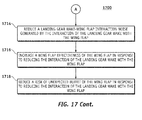
- FIG 17 is an illustration of an exemplary flowchart showing a process for reducing landing gear wake-wing flap interaction noise according to an embodiment of the disclosure.
- the various tasks performed in connection with process 1700 may be performed mechanically, by software, hardware, firmware, computer-readable software, computer readable storage medium, or any combination thereof. It should be appreciated that process 1700 may include any number of additional or alternative tasks, the tasks shown in Figure 17 need not be performed in the illustrated order, and the process 1700 may be incorporated into a more comprehensive procedure or process having additional functionality not described in detail herein.
- process 1700 may refer to elements mentioned above in connection with Figures 1-16 .
- portions of the process 1700 may be performed by different elements of the system 1600 such as: the landing gear door 304, the door flap 308, the leading edge section 306, the actuator 1602 etc.
- process 1700 may include any number of additional or alternative tasks, the tasks shown in Figure 17 need not be performed in the illustrated order, and the process 1700 may be incorporated into a more comprehensive procedure or process having additional functionality not described in detail herein.
- Process 1700 may have functions, material, and structures that are similar to the embodiments shown in Figures 3 , 5 , and 6-15 . Therefore, common features, functions, and elements may not be redundantly described here.
- Process 1700 may begin by deploying a landing gear door such as the landing gear door 304 comprising a trailing edge such as the trailing edge 310 and a leading edge such as the leading edge 312 (task 1702).
- a landing gear door such as the landing gear door 304 comprising a trailing edge such as the trailing edge 310 and a leading edge such as the leading edge 312 (task 1702).
- Process 1700 may continue by deflecting toward a landing gear strut such as the landing gear strut 322 a leading edge section such as the leading edge section 306 comprising the leading edge 312 and coupled to the landing gear door 304 (task 1704).
- a landing gear strut such as the landing gear strut 322
- a leading edge section such as the leading edge section 306 comprising the leading edge 312 and coupled to the landing gear door 304 (task 1704).
- Process 1700 may continue by deflecting toward the landing gear strut 322, a door flap such as the door flap 308 comprising the trailing edge 310 and hinged to the landing gear door 304 (task 1706).
- Process 1700 may continue by reducing a flow velocity on the pressure side 506 of the door flap 308, which is a pressure side of the landing gear door 304, due to deflecting the leading edge section 306 and the door flap 304 (task 1708).
- Process 1700 may continue by reducing a landing gear strut noise of the landing gear strut 322 in response to reducing the flow velocity (task 1710).
- Process 1700 may continue by reducing a landing gear wake such as the landing gear wake 402 impinging on a pressure side such as the pressure side 326 of a wing flap such as the wing flap 328 in response to reducing the flow velocity (task 1712).
- the leading edge section 306 reduces separation on the landing gear door 304, and thus reduces the wake deficit 1302.
- the deflected door flap 308 on the trailing edge 310 causes circulation around the landing gear strut 322, thereby reducing the local flow velocity 508. Reducing the local flow velocity 508 also reduces viscous losses around the landing gear strut 322, and thus reduces the landing gear wake 402 downstream of the landing gear strut 322.
- Process 1700 may continue by reducing a landing gear wake-wing flap interaction noise generated by the interaction of the landing gear wake 402 with the wing flap 328 (task 1714).
- Process 1700 may continue by increasing a wing flap effectiveness of the wing flap 328 in response to reducing the interaction of the landing gear wake 402 with the wing flap 328 (task 1716).
- Process 1700 may continue by reducing a risk of unexpected buffet of the wing flap 328 in response to reducing the interaction of the landing gear wake 402 with the wing flap 328 (task 1718).
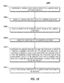
- Figure 18 is an illustration of an exemplary flowchart showing a process 1800 for configuring a quiet (low noise) landing gear door according to an embodiment of the disclosure.
- the various tasks performed in connection with process 1800 may be performed mechanically, by software, hardware, firmware, computer-readable software, computer readable storage medium, or any combination thereof. It should be appreciated that process 1800 may include any number of additional or alternative tasks, the tasks shown in Figure 18 need not be performed in the illustrated order, and the process 1800 may be incorporated into a more comprehensive procedure or process having additional functionality not described in detail herein.
- process 1800 may refer to elements mentioned above in connection with Figures 1-16 .
- portions of the process 1800 may be performed by different elements of the system 1600 such as: the landing gear door 304, the door flap 308, the leading edge section 306, the actuator 1602, etc.
- process 1800 may include any number of additional or alternative tasks, the tasks shown in Figure 18 need not be performed in the illustrated order, and the process 1800 may be incorporated into a more comprehensive procedure or process having additional functionality not described in detail herein.
- Process 1800 may have functions, material, and structures that are similar to the embodiments shown in Figures 3 , 5 , and 6-15. Therefore, common features, functions, and elements may not be redundantly described here.
- Process 1800 may begin by configuring a landing gear door such as the landing gear door 304 to deploy to a landing gear deployed position such as the landing gear deployed position 314 (task 1802).
- Process 1800 may continue by coupling a leading edge section such as the leading edge section 306 to the landing gear door 304 (task 1804).
- Process 1800 may continue by locating a door flap such as the door flap 308 at a percent chord plane of a landing gear door 304 (task 1806).
- Process 1800 may continue by hinging the door flap 308 to the landing gear door 304 (task 1808).
- Process 1800 may continue by configuring the leading edge section 306 and the door flap 308 to deflect toward a landing gear strut such as the landing gear strut 322 in the landing gear deployed position 314 to reduce a local flow speed near the landing gear strut 322 and minimize wake impinging on a pressure side such as the pressure side 326 of an aerodynamic surface such as the wing flap 328 of an aircraft such as the aircraft 200 such that a landing gear noise and landing gear wake-aerodynamic surface interaction noise are reduced (task 1810).
- Process 1800 may continue by coupling the landing gear door to a landing gear structure such as the landing gear structure 302 of an aircraft such as the aircraft 200 (task 1812).
- embodiments of the disclosure provide a quiet (reduced noise) landing gear door that reduces a landing gear noise and landing gear wake-aerodynamic surface interaction noise.
- computer program product may be used generally to refer to media such as, for example, memory, storage devices, storage unit, or other non-transitory media.
- computer-readable media may be involved in storing one or more instructions for use by the processor module 1608 to cause the processor module 1608 to perform specified operations.
- Such instructions generally referred to as “computer program code” or “program code” (which may be grouped in the form of computer programs or other groupings), when executed, enable the system 1600.
- operble means able to be used, fit or ready for use or service, usable for a specific purpose, and capable of performing a recited or desired function described herein.
- operble means the system and/or the device is fully functional and calibrated, comprises elements for, and meets applicable operability requirements to perform a recited function when activated.
- operble means the system and/or the circuit is fully functional and calibrated, comprises logic for, and meets applicable operability requirements to perform a recited function when activated.
Landscapes
- Engineering & Computer Science (AREA)
- Aviation & Aerospace Engineering (AREA)
- Mechanical Engineering (AREA)
- Gear Transmission (AREA)
- Gates (AREA)
Applications Claiming Priority (1)
| Application Number | Priority Date | Filing Date | Title |
|---|---|---|---|
| US13/689,766 US8944364B2 (en) | 2012-11-30 | 2012-11-30 | Quiet landing gear door |
Publications (3)
| Publication Number | Publication Date |
|---|---|
| EP2738089A2 true EP2738089A2 (fr) | 2014-06-04 |
| EP2738089A3 EP2738089A3 (fr) | 2015-12-16 |
| EP2738089B1 EP2738089B1 (fr) | 2020-01-22 |
Family
ID=49513809
Family Applications (1)
| Application Number | Title | Priority Date | Filing Date |
|---|---|---|---|
| EP13190893.1A Active EP2738089B1 (fr) | 2012-11-30 | 2013-10-30 | Trappe de train d'atterrissage silencieuse |
Country Status (2)
| Country | Link |
|---|---|
| US (2) | US8944364B2 (fr) |
| EP (1) | EP2738089B1 (fr) |
Cited By (6)
| Publication number | Priority date | Publication date | Assignee | Title |
|---|---|---|---|---|
| EP3106389A1 (fr) * | 2015-06-15 | 2016-12-21 | Airbus Operations, S.L. | Procede permettant de faire fonctionner un systeme de train d'atterrissage |
| FR3129365A1 (fr) * | 2021-11-25 | 2023-05-26 | Airbus Operations (S.A.S.) | Trappe de logement de train d’atterrissage d’aéronef |
| FR3129368A1 (fr) * | 2021-11-25 | 2023-05-26 | Airbus Operations (S.A.S.) | Système de train d’atterrissage d’aéronef |
| FR3129367A1 (fr) * | 2021-11-25 | 2023-05-26 | Airbus Operations (S.A.S.) | Trappe de logement de train d’atterrissage d’aéronef |
| FR3129369A1 (fr) * | 2021-11-25 | 2023-05-26 | Airbus Operations (S.A.S.) | Trappe de logement de train d’atterrissage d’aéronef |
| FR3136744A1 (fr) * | 2022-06-15 | 2023-12-22 | Safran Landing Systems | Atterrisseur d’aéronef à porte fixe équipé d’un volet et procédé de commande correspondant |
Families Citing this family (7)
| Publication number | Priority date | Publication date | Assignee | Title |
|---|---|---|---|---|
| WO2015134182A1 (fr) * | 2014-03-07 | 2015-09-11 | Gulfstream Aerospace Corporation | Agencements de train d'atterrissage avant comportant une feuille flexible et procédés permettant leur fabrication |
| US9290263B2 (en) * | 2014-03-07 | 2016-03-22 | Gulfstream Aerospace Corporation | Nose landing gear arrangements and methods for making the same |
| FR3045008B1 (fr) * | 2015-12-11 | 2018-01-12 | Airbus Operations | Procede et systeme pour la commande de trappes avant et arriere couplees d’une case de train d’atterrissage d’aeronef. |
| CN109292078B (zh) * | 2018-11-21 | 2020-09-29 | 周纯 | 一种新能源抗低能量损伤的飞机起落架组件 |
| US11964752B2 (en) | 2021-05-26 | 2024-04-23 | The Boeing Company | Acoustically treated landing gear door and method for reducing noise from landing gear of an aircraft |
| US12269593B2 (en) * | 2022-11-02 | 2025-04-08 | The Boeing Company | Wing assemblies and aircraft |
| GB2641203A (en) * | 2024-02-08 | 2025-11-26 | Safran Landing Systems Uk Ltd | Aircraft landing gear assembly |
Family Cites Families (8)
| Publication number | Priority date | Publication date | Assignee | Title |
|---|---|---|---|---|
| US4408736A (en) * | 1981-03-23 | 1983-10-11 | Grumman Aerospace Corporation | Landing gear door mud guard |
| NL1021077C2 (nl) * | 2002-07-15 | 2004-01-16 | Sp Aerospace And Vehicle Syste | Vliegtuig voorzien van geluidsreducerende middelen, alsmede landingsgestel en blaasmiddelen. |
| GB0225517D0 (en) * | 2002-11-01 | 2002-12-11 | Airbus Uk Ltd | Landing gear |
| GB0308002D0 (en) * | 2003-04-07 | 2003-05-14 | Airbus Uk Ltd | Landing gear door assembly |
| ES2277250T3 (es) * | 2003-04-07 | 2007-07-01 | Airbus Uk Limited | Conjunto de puertas de tren de aterrizaje. |
| FR2869013B1 (fr) * | 2004-04-20 | 2007-07-13 | Airbus France Sas | Deflecteur de flux aerodynamique pour train d'atterrissage d'aeronef |
| GB0812542D0 (en) * | 2008-07-09 | 2008-08-13 | Airbus Uk Ltd | Landing gear noise reduction assembley |
| JP5416988B2 (ja) * | 2009-02-24 | 2014-02-12 | 三菱重工業株式会社 | 降着装置及び降着装置用騒音低減デバイス |
-
2012
- 2012-11-30 US US13/689,766 patent/US8944364B2/en active Active
-
2013
- 2013-10-30 EP EP13190893.1A patent/EP2738089B1/fr active Active
-
2014
- 2014-12-21 US US14/578,473 patent/US9511851B2/en active Active
Non-Patent Citations (1)
| Title |
|---|
| None |
Cited By (8)
| Publication number | Priority date | Publication date | Assignee | Title |
|---|---|---|---|---|
| EP3106389A1 (fr) * | 2015-06-15 | 2016-12-21 | Airbus Operations, S.L. | Procede permettant de faire fonctionner un systeme de train d'atterrissage |
| US10179644B2 (en) | 2015-06-15 | 2019-01-15 | Airbus Operations, S.L. | Method for operating a landing gear system |
| FR3129365A1 (fr) * | 2021-11-25 | 2023-05-26 | Airbus Operations (S.A.S.) | Trappe de logement de train d’atterrissage d’aéronef |
| FR3129368A1 (fr) * | 2021-11-25 | 2023-05-26 | Airbus Operations (S.A.S.) | Système de train d’atterrissage d’aéronef |
| FR3129367A1 (fr) * | 2021-11-25 | 2023-05-26 | Airbus Operations (S.A.S.) | Trappe de logement de train d’atterrissage d’aéronef |
| FR3129369A1 (fr) * | 2021-11-25 | 2023-05-26 | Airbus Operations (S.A.S.) | Trappe de logement de train d’atterrissage d’aéronef |
| EP4186790A1 (fr) * | 2021-11-25 | 2023-05-31 | Airbus Operations Limited | Porte de travée de train d'atterrissage d'aéronef |
| FR3136744A1 (fr) * | 2022-06-15 | 2023-12-22 | Safran Landing Systems | Atterrisseur d’aéronef à porte fixe équipé d’un volet et procédé de commande correspondant |
Also Published As
| Publication number | Publication date |
|---|---|
| EP2738089B1 (fr) | 2020-01-22 |
| US20150102162A1 (en) | 2015-04-16 |
| US9511851B2 (en) | 2016-12-06 |
| EP2738089A3 (fr) | 2015-12-16 |
| US20140151498A1 (en) | 2014-06-05 |
| US8944364B2 (en) | 2015-02-03 |
Similar Documents
| Publication | Publication Date | Title |
|---|---|---|
| US9511851B2 (en) | Quiet landing gear door | |
| EP2669190A1 (fr) | Aileron à entrefer de portance élevée actionné par rotation | |
| US9776705B2 (en) | Shape memory alloy actuator system for composite aircraft structures | |
| US8657238B2 (en) | Retractable vortex generator for reducing stall speed | |
| EP2796365A2 (fr) | Krueger à carrossage variable 2 positions en position élevée | |
| US9446843B2 (en) | Enhanced performance rotorcraft rotor blade | |
| BR102012020561A2 (pt) | Corpo fluido - dinâmico de curvatura variável utilizando materiais inteligentes otimizados | |
| BR102013003091A2 (pt) | Curvatura de krueger variável em três posições em posição elevada | |
| Pecora et al. | KRISTINA: Kinematic rib-based structural system for innovative adaptive trailing edge | |
| US10252792B2 (en) | Flow disruption devices for the reduction of high lift system noise | |
| Storms et al. | Aeroacoustic measurements of slat noise on a three-dimensional high-lift system | |
| Lockard et al. | Noise simulations of the high-lift common research model | |
| Gardner et al. | Reduction of dynamic stall using a back-flow flap | |
| Keller et al. | Numerical investigations of aerodynamic properties of a propeller blown circulation control system on a high wing aircraft | |
| CN109328163B (zh) | 用于展开相邻的后缘襟翼的方法和系统 | |
| Zhang | Airframe noise–high lift device noise | |
| Szulc | Rotorcraft thickness noise control | |
| Pecora et al. | Structural design of an adaptive wing trailing edge for large aeroplanes | |
| EP3756997A1 (fr) | Dispositif de déclenchement pour améliorer les performances et la maniabilité d'un aéronef | |
| US8573354B1 (en) | Noise suppression system for hollow vehicle fasteners | |
| Auteri et al. | Aerodynamic evaluation | |
| Meyer | Actuated Adaptive Wingtips on Transport Aircraft | |
| Harrison | Separation control on high lift systems using vane vortex generators | |
| Ai et al. | Experimental and Numerical Studies of Flow and Noise Control of Aerofoils using Morphing Structures | |
| Cook | A Computational Investigation of Circulation Control |
Legal Events
| Date | Code | Title | Description |
|---|---|---|---|
| PUAI | Public reference made under article 153(3) epc to a published international application that has entered the european phase |
Free format text: ORIGINAL CODE: 0009012 |
|
| 17P | Request for examination filed |
Effective date: 20131030 |
|
| AK | Designated contracting states |
Kind code of ref document: A2 Designated state(s): AL AT BE BG CH CY CZ DE DK EE ES FI FR GB GR HR HU IE IS IT LI LT LU LV MC MK MT NL NO PL PT RO RS SE SI SK SM TR |
|
| AX | Request for extension of the european patent |
Extension state: BA ME |
|
| PUAL | Search report despatched |
Free format text: ORIGINAL CODE: 0009013 |
|
| AK | Designated contracting states |
Kind code of ref document: A3 Designated state(s): AL AT BE BG CH CY CZ DE DK EE ES FI FR GB GR HR HU IE IS IT LI LT LU LV MC MK MT NL NO PL PT RO RS SE SI SK SM TR |
|
| AX | Request for extension of the european patent |
Extension state: BA ME |
|
| RIC1 | Information provided on ipc code assigned before grant |
Ipc: B64C 25/16 20060101AFI20151109BHEP |
|
| R17P | Request for examination filed (corrected) |
Effective date: 20160609 |
|
| RBV | Designated contracting states (corrected) |
Designated state(s): AL AT BE BG CH CY CZ DE DK EE ES FI FR GB GR HR HU IE IS IT LI LT LU LV MC MK MT NL NO PL PT RO RS SE SI SK SM TR |
|
| GRAP | Despatch of communication of intention to grant a patent |
Free format text: ORIGINAL CODE: EPIDOSNIGR1 |
|
| STAA | Information on the status of an ep patent application or granted ep patent |
Free format text: STATUS: GRANT OF PATENT IS INTENDED |
|
| INTG | Intention to grant announced |
Effective date: 20180629 |
|
| GRAJ | Information related to disapproval of communication of intention to grant by the applicant or resumption of examination proceedings by the epo deleted |
Free format text: ORIGINAL CODE: EPIDOSDIGR1 |
|
| STAA | Information on the status of an ep patent application or granted ep patent |
Free format text: STATUS: REQUEST FOR EXAMINATION WAS MADE |
|
| STAA | Information on the status of an ep patent application or granted ep patent |
Free format text: STATUS: EXAMINATION IS IN PROGRESS |
|
| INTC | Intention to grant announced (deleted) | ||
| 17Q | First examination report despatched |
Effective date: 20181113 |
|
| GRAP | Despatch of communication of intention to grant a patent |
Free format text: ORIGINAL CODE: EPIDOSNIGR1 |
|
| STAA | Information on the status of an ep patent application or granted ep patent |
Free format text: STATUS: GRANT OF PATENT IS INTENDED |
|
| INTG | Intention to grant announced |
Effective date: 20190731 |
|
| RIN1 | Information on inventor provided before grant (corrected) |
Inventor name: WETZEL, DREW A. Inventor name: LANGTRY, ROBIN B. |
|
| GRAS | Grant fee paid |
Free format text: ORIGINAL CODE: EPIDOSNIGR3 |
|
| GRAA | (expected) grant |
Free format text: ORIGINAL CODE: 0009210 |
|
| STAA | Information on the status of an ep patent application or granted ep patent |
Free format text: STATUS: THE PATENT HAS BEEN GRANTED |
|
| AK | Designated contracting states |
Kind code of ref document: B1 Designated state(s): AL AT BE BG CH CY CZ DE DK EE ES FI FR GB GR HR HU IE IS IT LI LT LU LV MC MK MT NL NO PL PT RO RS SE SI SK SM TR |
|
| REG | Reference to a national code |
Ref country code: GB Ref legal event code: FG4D |
|
| REG | Reference to a national code |
Ref country code: CH Ref legal event code: EP |
|
| REG | Reference to a national code |
Ref country code: DE Ref legal event code: R096 Ref document number: 602013065251 Country of ref document: DE |
|
| REG | Reference to a national code |
Ref country code: AT Ref legal event code: REF Ref document number: 1226761 Country of ref document: AT Kind code of ref document: T Effective date: 20200215 |
|
| REG | Reference to a national code |
Ref country code: IE Ref legal event code: FG4D |
|
| REG | Reference to a national code |
Ref country code: NL Ref legal event code: MP Effective date: 20200122 |
|
| REG | Reference to a national code |
Ref country code: LT Ref legal event code: MG4D |
|
| PG25 | Lapsed in a contracting state [announced via postgrant information from national office to epo] |
Ref country code: FI Free format text: LAPSE BECAUSE OF FAILURE TO SUBMIT A TRANSLATION OF THE DESCRIPTION OR TO PAY THE FEE WITHIN THE PRESCRIBED TIME-LIMIT Effective date: 20200122 Ref country code: NO Free format text: LAPSE BECAUSE OF FAILURE TO SUBMIT A TRANSLATION OF THE DESCRIPTION OR TO PAY THE FEE WITHIN THE PRESCRIBED TIME-LIMIT Effective date: 20200422 Ref country code: RS Free format text: LAPSE BECAUSE OF FAILURE TO SUBMIT A TRANSLATION OF THE DESCRIPTION OR TO PAY THE FEE WITHIN THE PRESCRIBED TIME-LIMIT Effective date: 20200122 Ref country code: PT Free format text: LAPSE BECAUSE OF FAILURE TO SUBMIT A TRANSLATION OF THE DESCRIPTION OR TO PAY THE FEE WITHIN THE PRESCRIBED TIME-LIMIT Effective date: 20200614 Ref country code: NL Free format text: LAPSE BECAUSE OF FAILURE TO SUBMIT A TRANSLATION OF THE DESCRIPTION OR TO PAY THE FEE WITHIN THE PRESCRIBED TIME-LIMIT Effective date: 20200122 |
|
| PG25 | Lapsed in a contracting state [announced via postgrant information from national office to epo] |
Ref country code: IS Free format text: LAPSE BECAUSE OF FAILURE TO SUBMIT A TRANSLATION OF THE DESCRIPTION OR TO PAY THE FEE WITHIN THE PRESCRIBED TIME-LIMIT Effective date: 20200522 Ref country code: BG Free format text: LAPSE BECAUSE OF FAILURE TO SUBMIT A TRANSLATION OF THE DESCRIPTION OR TO PAY THE FEE WITHIN THE PRESCRIBED TIME-LIMIT Effective date: 20200422 Ref country code: GR Free format text: LAPSE BECAUSE OF FAILURE TO SUBMIT A TRANSLATION OF THE DESCRIPTION OR TO PAY THE FEE WITHIN THE PRESCRIBED TIME-LIMIT Effective date: 20200423 Ref country code: LV Free format text: LAPSE BECAUSE OF FAILURE TO SUBMIT A TRANSLATION OF THE DESCRIPTION OR TO PAY THE FEE WITHIN THE PRESCRIBED TIME-LIMIT Effective date: 20200122 Ref country code: SE Free format text: LAPSE BECAUSE OF FAILURE TO SUBMIT A TRANSLATION OF THE DESCRIPTION OR TO PAY THE FEE WITHIN THE PRESCRIBED TIME-LIMIT Effective date: 20200122 Ref country code: HR Free format text: LAPSE BECAUSE OF FAILURE TO SUBMIT A TRANSLATION OF THE DESCRIPTION OR TO PAY THE FEE WITHIN THE PRESCRIBED TIME-LIMIT Effective date: 20200122 |
|
| REG | Reference to a national code |
Ref country code: DE Ref legal event code: R097 Ref document number: 602013065251 Country of ref document: DE |
|
| PG25 | Lapsed in a contracting state [announced via postgrant information from national office to epo] |
Ref country code: DK Free format text: LAPSE BECAUSE OF FAILURE TO SUBMIT A TRANSLATION OF THE DESCRIPTION OR TO PAY THE FEE WITHIN THE PRESCRIBED TIME-LIMIT Effective date: 20200122 Ref country code: ES Free format text: LAPSE BECAUSE OF FAILURE TO SUBMIT A TRANSLATION OF THE DESCRIPTION OR TO PAY THE FEE WITHIN THE PRESCRIBED TIME-LIMIT Effective date: 20200122 Ref country code: LT Free format text: LAPSE BECAUSE OF FAILURE TO SUBMIT A TRANSLATION OF THE DESCRIPTION OR TO PAY THE FEE WITHIN THE PRESCRIBED TIME-LIMIT Effective date: 20200122 Ref country code: RO Free format text: LAPSE BECAUSE OF FAILURE TO SUBMIT A TRANSLATION OF THE DESCRIPTION OR TO PAY THE FEE WITHIN THE PRESCRIBED TIME-LIMIT Effective date: 20200122 Ref country code: SK Free format text: LAPSE BECAUSE OF FAILURE TO SUBMIT A TRANSLATION OF THE DESCRIPTION OR TO PAY THE FEE WITHIN THE PRESCRIBED TIME-LIMIT Effective date: 20200122 Ref country code: CZ Free format text: LAPSE BECAUSE OF FAILURE TO SUBMIT A TRANSLATION OF THE DESCRIPTION OR TO PAY THE FEE WITHIN THE PRESCRIBED TIME-LIMIT Effective date: 20200122 Ref country code: EE Free format text: LAPSE BECAUSE OF FAILURE TO SUBMIT A TRANSLATION OF THE DESCRIPTION OR TO PAY THE FEE WITHIN THE PRESCRIBED TIME-LIMIT Effective date: 20200122 Ref country code: SM Free format text: LAPSE BECAUSE OF FAILURE TO SUBMIT A TRANSLATION OF THE DESCRIPTION OR TO PAY THE FEE WITHIN THE PRESCRIBED TIME-LIMIT Effective date: 20200122 |
|
| REG | Reference to a national code |
Ref country code: AT Ref legal event code: MK05 Ref document number: 1226761 Country of ref document: AT Kind code of ref document: T Effective date: 20200122 |
|
| PLBE | No opposition filed within time limit |
Free format text: ORIGINAL CODE: 0009261 |
|
| STAA | Information on the status of an ep patent application or granted ep patent |
Free format text: STATUS: NO OPPOSITION FILED WITHIN TIME LIMIT |
|
| 26N | No opposition filed |
Effective date: 20201023 |
|
| PG25 | Lapsed in a contracting state [announced via postgrant information from national office to epo] |
Ref country code: AT Free format text: LAPSE BECAUSE OF FAILURE TO SUBMIT A TRANSLATION OF THE DESCRIPTION OR TO PAY THE FEE WITHIN THE PRESCRIBED TIME-LIMIT Effective date: 20200122 |
|
| PG25 | Lapsed in a contracting state [announced via postgrant information from national office to epo] |
Ref country code: SI Free format text: LAPSE BECAUSE OF FAILURE TO SUBMIT A TRANSLATION OF THE DESCRIPTION OR TO PAY THE FEE WITHIN THE PRESCRIBED TIME-LIMIT Effective date: 20200122 Ref country code: PL Free format text: LAPSE BECAUSE OF FAILURE TO SUBMIT A TRANSLATION OF THE DESCRIPTION OR TO PAY THE FEE WITHIN THE PRESCRIBED TIME-LIMIT Effective date: 20200122 |
|
| REG | Reference to a national code |
Ref country code: CH Ref legal event code: PL |
|
| PG25 | Lapsed in a contracting state [announced via postgrant information from national office to epo] |
Ref country code: LU Free format text: LAPSE BECAUSE OF NON-PAYMENT OF DUE FEES Effective date: 20201030 Ref country code: MC Free format text: LAPSE BECAUSE OF FAILURE TO SUBMIT A TRANSLATION OF THE DESCRIPTION OR TO PAY THE FEE WITHIN THE PRESCRIBED TIME-LIMIT Effective date: 20200122 |
|
| REG | Reference to a national code |
Ref country code: BE Ref legal event code: MM Effective date: 20201031 |
|
| PG25 | Lapsed in a contracting state [announced via postgrant information from national office to epo] |
Ref country code: LI Free format text: LAPSE BECAUSE OF NON-PAYMENT OF DUE FEES Effective date: 20201031 Ref country code: CH Free format text: LAPSE BECAUSE OF NON-PAYMENT OF DUE FEES Effective date: 20201031 Ref country code: BE Free format text: LAPSE BECAUSE OF NON-PAYMENT OF DUE FEES Effective date: 20201031 |
|
| PG25 | Lapsed in a contracting state [announced via postgrant information from national office to epo] |
Ref country code: IE Free format text: LAPSE BECAUSE OF NON-PAYMENT OF DUE FEES Effective date: 20201030 |
|
| PG25 | Lapsed in a contracting state [announced via postgrant information from national office to epo] |
Ref country code: TR Free format text: LAPSE BECAUSE OF FAILURE TO SUBMIT A TRANSLATION OF THE DESCRIPTION OR TO PAY THE FEE WITHIN THE PRESCRIBED TIME-LIMIT Effective date: 20200122 Ref country code: MT Free format text: LAPSE BECAUSE OF FAILURE TO SUBMIT A TRANSLATION OF THE DESCRIPTION OR TO PAY THE FEE WITHIN THE PRESCRIBED TIME-LIMIT Effective date: 20200122 Ref country code: CY Free format text: LAPSE BECAUSE OF FAILURE TO SUBMIT A TRANSLATION OF THE DESCRIPTION OR TO PAY THE FEE WITHIN THE PRESCRIBED TIME-LIMIT Effective date: 20200122 |
|
| PG25 | Lapsed in a contracting state [announced via postgrant information from national office to epo] |
Ref country code: MK Free format text: LAPSE BECAUSE OF FAILURE TO SUBMIT A TRANSLATION OF THE DESCRIPTION OR TO PAY THE FEE WITHIN THE PRESCRIBED TIME-LIMIT Effective date: 20200122 Ref country code: AL Free format text: LAPSE BECAUSE OF FAILURE TO SUBMIT A TRANSLATION OF THE DESCRIPTION OR TO PAY THE FEE WITHIN THE PRESCRIBED TIME-LIMIT Effective date: 20200122 |
|
| P01 | Opt-out of the competence of the unified patent court (upc) registered |
Effective date: 20230516 |
|
| PGFP | Annual fee paid to national office [announced via postgrant information from national office to epo] |
Ref country code: DE Payment date: 20251029 Year of fee payment: 13 |
|
| PGFP | Annual fee paid to national office [announced via postgrant information from national office to epo] |
Ref country code: GB Payment date: 20251027 Year of fee payment: 13 |
|
| PGFP | Annual fee paid to national office [announced via postgrant information from national office to epo] |
Ref country code: IT Payment date: 20251021 Year of fee payment: 13 |
|
| PGFP | Annual fee paid to national office [announced via postgrant information from national office to epo] |
Ref country code: FR Payment date: 20251027 Year of fee payment: 13 |