EP2738423A1 - Dispositif d'entraînement à chaîne pour entraînement d'arbre à cames - Google Patents
Dispositif d'entraînement à chaîne pour entraînement d'arbre à cames Download PDFInfo
- Publication number
- EP2738423A1 EP2738423A1 EP12818007.2A EP12818007A EP2738423A1 EP 2738423 A1 EP2738423 A1 EP 2738423A1 EP 12818007 A EP12818007 A EP 12818007A EP 2738423 A1 EP2738423 A1 EP 2738423A1
- Authority
- EP
- European Patent Office
- Prior art keywords
- chain
- rollers
- timing chain
- guide
- timing
- Prior art date
- Legal status (The legal status is an assumption and is not a legal conclusion. Google has not performed a legal analysis and makes no representation as to the accuracy of the status listed.)
- Granted
Links
Images



Classifications
-
- F—MECHANICAL ENGINEERING; LIGHTING; HEATING; WEAPONS; BLASTING
- F16—ENGINEERING ELEMENTS AND UNITS; GENERAL MEASURES FOR PRODUCING AND MAINTAINING EFFECTIVE FUNCTIONING OF MACHINES OR INSTALLATIONS; THERMAL INSULATION IN GENERAL
- F16H—GEARING
- F16H7/00—Gearings for conveying rotary motion by endless flexible members
- F16H7/08—Means for varying tension of belts, ropes or chains
-
- F—MECHANICAL ENGINEERING; LIGHTING; HEATING; WEAPONS; BLASTING
- F16—ENGINEERING ELEMENTS AND UNITS; GENERAL MEASURES FOR PRODUCING AND MAINTAINING EFFECTIVE FUNCTIONING OF MACHINES OR INSTALLATIONS; THERMAL INSULATION IN GENERAL
- F16H—GEARING
- F16H7/00—Gearings for conveying rotary motion by endless flexible members
- F16H7/18—Means for guiding or supporting belts, ropes, or chains
-
- F—MECHANICAL ENGINEERING; LIGHTING; HEATING; WEAPONS; BLASTING
- F02—COMBUSTION ENGINES; HOT-GAS OR COMBUSTION-PRODUCT ENGINE PLANTS
- F02B—INTERNAL-COMBUSTION PISTON ENGINES; COMBUSTION ENGINES IN GENERAL
- F02B67/00—Engines characterised by the arrangement of auxiliary apparatus not being otherwise provided for, e.g. the apparatus having different functions; Driving auxiliary apparatus from engines, not otherwise provided for
- F02B67/04—Engines characterised by the arrangement of auxiliary apparatus not being otherwise provided for, e.g. the apparatus having different functions; Driving auxiliary apparatus from engines, not otherwise provided for of mechanically-driven auxiliary apparatus
- F02B67/06—Engines characterised by the arrangement of auxiliary apparatus not being otherwise provided for, e.g. the apparatus having different functions; Driving auxiliary apparatus from engines, not otherwise provided for of mechanically-driven auxiliary apparatus driven by means of chains, belts, or like endless members
-
- F—MECHANICAL ENGINEERING; LIGHTING; HEATING; WEAPONS; BLASTING
- F16—ENGINEERING ELEMENTS AND UNITS; GENERAL MEASURES FOR PRODUCING AND MAINTAINING EFFECTIVE FUNCTIONING OF MACHINES OR INSTALLATIONS; THERMAL INSULATION IN GENERAL
- F16H—GEARING
- F16H7/00—Gearings for conveying rotary motion by endless flexible members
- F16H7/06—Gearings for conveying rotary motion by endless flexible members with chains
-
- F—MECHANICAL ENGINEERING; LIGHTING; HEATING; WEAPONS; BLASTING
- F16—ENGINEERING ELEMENTS AND UNITS; GENERAL MEASURES FOR PRODUCING AND MAINTAINING EFFECTIVE FUNCTIONING OF MACHINES OR INSTALLATIONS; THERMAL INSULATION IN GENERAL
- F16H—GEARING
- F16H7/00—Gearings for conveying rotary motion by endless flexible members
- F16H7/08—Means for varying tension of belts, ropes or chains
- F16H2007/0863—Finally actuated members, e.g. constructional details thereof
- F16H2007/0865—Pulleys
-
- F—MECHANICAL ENGINEERING; LIGHTING; HEATING; WEAPONS; BLASTING
- F16—ENGINEERING ELEMENTS AND UNITS; GENERAL MEASURES FOR PRODUCING AND MAINTAINING EFFECTIVE FUNCTIONING OF MACHINES OR INSTALLATIONS; THERMAL INSULATION IN GENERAL
- F16H—GEARING
- F16H7/00—Gearings for conveying rotary motion by endless flexible members
- F16H7/08—Means for varying tension of belts, ropes or chains
- F16H2007/0863—Finally actuated members, e.g. constructional details thereof
- F16H2007/0872—Sliding members
-
- F—MECHANICAL ENGINEERING; LIGHTING; HEATING; WEAPONS; BLASTING
- F16—ENGINEERING ELEMENTS AND UNITS; GENERAL MEASURES FOR PRODUCING AND MAINTAINING EFFECTIVE FUNCTIONING OF MACHINES OR INSTALLATIONS; THERMAL INSULATION IN GENERAL
- F16H—GEARING
- F16H7/00—Gearings for conveying rotary motion by endless flexible members
- F16H7/08—Means for varying tension of belts, ropes or chains
- F16H2007/0889—Path of movement of the finally actuated member
- F16H2007/0893—Circular path
-
- F—MECHANICAL ENGINEERING; LIGHTING; HEATING; WEAPONS; BLASTING
- F16—ENGINEERING ELEMENTS AND UNITS; GENERAL MEASURES FOR PRODUCING AND MAINTAINING EFFECTIVE FUNCTIONING OF MACHINES OR INSTALLATIONS; THERMAL INSULATION IN GENERAL
- F16H—GEARING
- F16H7/00—Gearings for conveying rotary motion by endless flexible members
- F16H7/08—Means for varying tension of belts, ropes or chains
- F16H7/10—Means for varying tension of belts, ropes or chains by adjusting the axis of a pulley
- F16H7/12—Means for varying tension of belts, ropes or chains by adjusting the axis of a pulley of an idle pulley
- F16H7/1254—Means for varying tension of belts, ropes or chains by adjusting the axis of a pulley of an idle pulley without vibration damping means
- F16H7/1281—Means for varying tension of belts, ropes or chains by adjusting the axis of a pulley of an idle pulley without vibration damping means where the axis of the pulley moves along a substantially circular path
-
- F—MECHANICAL ENGINEERING; LIGHTING; HEATING; WEAPONS; BLASTING
- F16—ENGINEERING ELEMENTS AND UNITS; GENERAL MEASURES FOR PRODUCING AND MAINTAINING EFFECTIVE FUNCTIONING OF MACHINES OR INSTALLATIONS; THERMAL INSULATION IN GENERAL
- F16H—GEARING
- F16H7/00—Gearings for conveying rotary motion by endless flexible members
- F16H7/18—Means for guiding or supporting belts, ropes, or chains
- F16H7/20—Mountings for rollers or pulleys
Definitions
- the present invention relates to a chain transmission device for driving a camshaft.
- a pivotable chain guide is provided on one side of the slack side of the timing chain, and adjustment force of a chain tensioner is applied to a remote end of the chain guide from the center of pivoting movement of the chain guide to tighten the timing chain, thereby preventing the chain from becoming slack and flapping.
- Another chain guide is fixed in position on the tight side of the timing chain to guide the movement of the timing chain, thereby further reducing flapping of the chain.
- One known chain guide for adjusting the tension and for guiding the movement of the timing chain is configured to guide the timing chain by sliding contact with its surface.
- this chain guide has a problem in that the movement resistance of the timing chain is large and a transmission torque loss is significant.
- Patent Document 1 proposes a chain guide in which both ends of a plurality of roller shafts arranged in a curve form are supported by a guide base elongated in the moving direction of a timing chain, rollers in the form of roller bearings are rotatably supported on the respective roller shafts, and the timing chain is movably supported by the plurality of rollers.
- Patent Document 1 International Publication No. 2010/090139
- An object of the present invention is to prevent insufficient lubrication of chain guiding rollers in a chain transmission device for driving a camshaft, and to make it easier to properly lay out the engine.
- the present invention provides a chain transmission device for driving a camshaft, including a driving sprocket mounted to a crankshaft, a driven sprocket mounted to a camshaft, a timing chain looped over the driving sprocket and the driven sprocket, a pivotable chain guide provided on one side of the slack side of the timing chain, and retaining a plurality of rotatable rollers for guiding movements of the timing chain, the rollers being spaced from each other in the direction in which the timing chain is moved, and a chain tensioner for applying an adjustment force to a remote end of the chain guide remote from the center of pivoting movement of the chain guide, thereby pressing the rollers against the timing chain, wherein the ratio (D 1 /D 2 ) between the pitch circle diameter D 1 of the driving sprocket and the outer diameter D 2 of the rollers is set within the range of 5/3 to 5/1.
- the maximum rotation speed of the crankshaft in an engine is generally about 8,000 rpm.
- the ratio (D 1 /D 2 ) between the pitch circle diameter D 1 of the driving sprocket attached to the crankshaft and the outer diameter D 2 of the rollers is set at 5/1 or less as described above, the rollers never rotate at a speed exceeding 40,000 rpm, thus preventing insufficient lubrication of the rollers.
- the driving sprocket provided on the crankshaft normally has a pitch circle diameter ⁇ of about 40 to 50 mm.
- the ratio (D 1 /D 2 ) between the pitch circle diameter D 1 of the driving sprocket and the outer diameter D 2 of the rollers is set at 5/3 or more, the outer diameter ⁇ of the rollers never exceeds 30.0 mm, so that it is easier to lay out the engine.
- Such small-diameter rollers are also lighter in weight and thus easier to handle.
- This chain transmission device may further include a fixed chain guide provided on one side of the tight side of the timing chain, and having the same configuration as the pivotable chain guide to further effectively prevent flapping of the timing chain.
- the rollers may be needle roller bearings or cylindrical roller bearings each having an outer race and a plurality of roller elements received in the outer race. With this arrangement, the rollers can be smoothly rotated by contact with the timing chain, so that movement resistance of the timing chain can be reduced to a large extent.
- the ratio (D 1 /D 2 ) between the pitch circle diameter D 1 of the driving sprocket and the outer diameter D 2 of the rollers is set within the range of 5/3 to 5/1, it is possible to prevent insufficient lubrication of the rollers even while the engine speed is high.
- the diameter of the rollers is not increased more than necessary, so as to make the engine layout easier.
- Fig. 1 shows a chain transmission device for driving camshafts in which a timing chain 5 is looped over a driving sprocket 2 mounted to one end of a crankshaft 1 and driven sprockets 4 mounted to ends of respective two camshafts 3.
- the timing chain 5 may be a roller chain or a silent chain.
- the crankshaft 1 is rotated in the direction shown by the corresponding arrow of Fig. 1 .
- the timing chain 5 moves in the direction shown by the corresponding arrow of Fig. 1 .
- the portion of the chain 5 extending from the driving sprocket 2 to the driven sprocket 4 positioned on the left side of Fig. 1 becomes slack (this side of the chain is thus referred to as the "slack side 5a"), and the portion of the chain extending from the other driven sprocket 4 to the driving sprocket 2 becomes tight (“tight side 5b").
- a chain guide A 1 is provided on one side of the slack side 5a of the chain 5.
- the chain guide A 1 is elongated in the moving direction of the timing chain 5.
- the chain guide A 1 has its upper end supported by a pivot shaft 14 protruding from an engine block so as to be pivotable about the pivot shaft 14. Adjustment force of a chain tensioner 15 is applied to the lower end, i.e. the end remote from the pivot shaft 14, of the chain guide A 1 , so that this end of the chain guide is pressed against the slack side 5a of the chain.
- a chain guide A 2 is provided on the opposite side of the tight side 5b of the timing chain 5. As with the pivotable chain guide A 1 , this chain guide A 2 is elongated in the moving direction of the timing chain 5, with both ends thereof fixed by fastening bolts 16 screwed into the engine block, to guide the movement of the timing chain 5.
- the pivotable chain guide A 1 and the fixed chain guide A 2 have the same configuration, except that the pivotable chain guide A 1 has at one end thereof an insertion hole 24 into which a shaft can be is inserted, whereas the fixed chain guide A 2 has at both ends thereof insertion holes into which bolts can be inserted.
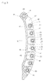
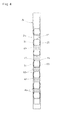
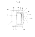
- the chain guide A 1 includes a guide base 21 elongated in the moving direction of the timing chain 5, a plurality of roller shafts 31 spaced from each other in the longitudinal direction of the guide base 21, and a plurality of chain guiding rollers 41 rotatably supported on the respective roller shafts 31.
- the guide base 21 includes an opposed pair of side plate portions 22, and a plurality of space retaining plates 23 provided between the side plate portions 22 and spaced from each other in the longitudinal direction.
- the side plate portions 22 are arch-shaped, and connected together at their upper ends by a portion formed with the insertion hole 24 into which the pivot shaft 14 is inserted.
- a plurality of bearing recesses 25 for supporting the shaft ends of the roller shafts 31 are formed in the opposed inner surfaces of the respective side plate portions 22 so as to be spaced from each other in the longitudinal direction of the side plate portions 22.
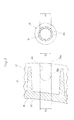
- the bearing recesses 25 each include a tapered groove portion 25a extending in the width direction of the side plate portion 22 from the outer side surface of the side plate portion 22, i.e. its surface facing the timing chain 5, and having a first end open to the outer side surface and a second opposite end narrower than the first end, and a circular recess portion 25b connected to the second narrow end of the tapered groove portion 25a and serving as a shaft support portion.
- the roller shafts 31 can be passed through the respective tapered groove portions 25a and fitted into and supported by the circular recess portions 25b.
- This chain guide is designed to satisfy the relation d 10 > D 12 > D 11 , where D 1 is the width of the second narrow ends of the tapered groove portions 25a, D 12 is the inner diameter of the circular recess portions 25b, and d 10 is the outer diameter of the roller shafts 31.
- the bearing recesses 25 are arranged such that the centers of the circular recess portions 25b lie on a convex circular arc. But they may be arranged such that the centers of the circular recess portions 25b lie on a curved line other than a convex circular arc.
- the guide base 21 is formed by molding synthetic resin.
- synthetic resin a resin excellent in oil resistance, weather resistance, and strength is preferably used.
- resins include polyamide 46 (PA 46) and polyamide 66 (PA 66).
- PA 46 polyamide 46
- PA 66 polyamide 66
- reinforcing glass fiber is preferably mixed into the resin.
- the guide base 21 may be formed by casting or die-casting a light metal such as an aluminum alloy and a magnesium alloy.
- the roller shafts 31 are fitted in the respective bearing recesses 25.
- the roller shafts 31 are made of SUJ2 or SC material.
- the roller shafts 31 are thermally treated to enhance hardness. As the thermal treatment, bright quenching is used in the embodiment. However, high frequency quenching or carburizing quenching may be performed instead. Alternatively, nitrocarburizing quenching may be performed.
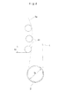
- the rollers 41 are rotatably supported on the respective roller shafts 31. As shown in Fig. 6 , in the embodiment, needle roller bearings are used as the rollers 41.
- Each of the needle roller bearings 41 includes an outer race 42, a plurality of needle roller elements 43 received in the outer race, and a retainer 44 retaining the needle roller elements 43.
- the outer race 42 is formed into a shell shape by drawing a metal plate of SPC or SCM, and hardened by thermal treatment.
- the metal plate to be formed into the outer race 42 is preferably thin. However, if a thin metal plate is used, the cylindricity is lowered during thermal treatment. Therefore, when the timing chain 5 is guided, abnormal noises are generated due to contact between the outer race 42 and the timing chain 5.
- a thick metal plate having thickness of about 1 mm to 3 mm is used and drawn in the embodiment.
- Inwardly extending flanges 46 for retaining the retainer 44 are formed at both ends of the shell-shaped outer race 42. In order to more easily install the needle roller bearings- 41, the inwardly extending flanges 46 are formed by bending after installing the retainer 44 for retaining the needle roller elements 43.
- the driving sprocket 2 and the rollers 41 are designed such that the ratio (D 1 /D 2 ) between the pitch circle diameter D 1 of the driving sprocket 2 and the outer diameter D 2 of the rollers is 5/3 to 5/1.
- the pitch circle diameter ⁇ of the driving sprocket 2 is about 40 to 50 mm. Therefore, the outer diameter of the rollers 41 is determined at about 8 to 30 mm in the embodiment.
- the outer races 42 of the needle roller bearings may be formed by shaving.
- cylindrical roller bearings 41 may be used in place of such needle roller bearings. In either case, the roller bearings may be full type roller bearings, i.e. bearings without a retainer.
- the reference numeral 42 denotes outer races of the cylindrical roller bearings 41
- the reference numeral 43 denotes cylindrical roller elements.
- timing chain 5 Since the timing chain 5 is guided while being in rolling contact with the rollers 41 in the above manner, movement resistance of the timing chain 5 is insignificant, so that the timing chain 5 smoothly moves, and the torque is transmitted without loss.
- the rollers 41 rotate at such high speed that lubrication becomes insufficient at contact portions between the outer races 42 and the needle roller elements (cylindrical roller elements) 43 and/or at contact portions between the needle roller elements (cylindrical roller elements) 43 and the roller shafts 31.
- the outer diameter of the rollers 41 tends to be large to such an extent as to make proper layout of the engine difficult.
- the rollers 41 are heavy too.
- the ratio (D 1 /D 2 ) between the pitch circle diameter D 1 of the driving sprocket 2 attached to the crankshaft 1 and the outer diameter D 2 of the rollers 41 is determined at 5/1 or less. the rollers 41 never rotate at a speed exceeding 40000 rpm. This prevents insufficient lubrication at contact portions of the needle roller elements (cylindrical roller elements) 43.
- the driving sprocket 2 provided on the crankshaft 1 normally has a pitch circle diameter ⁇ of about 40 to 50 mm, and the ratio (D 1 /D 2 ) between the pitch circle diameter D 1 of the driving sprocket 2 and the outer diameter D 2 of the rollers is set at 5/3 or more, the outer diameter ⁇ of the rollers 41 never exceeds 30.0 mm. Therefore, the rollers are lighter in weight and thus can be more easily handled. It is easy to lay out the engine too.
Landscapes
- Engineering & Computer Science (AREA)
- General Engineering & Computer Science (AREA)
- Mechanical Engineering (AREA)
- Chemical & Material Sciences (AREA)
- Combustion & Propulsion (AREA)
- Devices For Conveying Motion By Means Of Endless Flexible Members (AREA)
Applications Claiming Priority (2)
| Application Number | Priority Date | Filing Date | Title |
|---|---|---|---|
| JP2011161828A JP5706261B2 (ja) | 2011-07-25 | 2011-07-25 | カム軸駆動用のチェーン伝動装置 |
| PCT/JP2012/068176 WO2013015166A1 (fr) | 2011-07-25 | 2012-07-18 | Dispositif d'entraînement à chaîne pour entraînement d'arbre à cames |
Publications (3)
| Publication Number | Publication Date |
|---|---|
| EP2738423A1 true EP2738423A1 (fr) | 2014-06-04 |
| EP2738423A4 EP2738423A4 (fr) | 2015-04-08 |
| EP2738423B1 EP2738423B1 (fr) | 2017-01-11 |
Family
ID=47601016
Family Applications (1)
| Application Number | Title | Priority Date | Filing Date |
|---|---|---|---|
| EP12818007.2A Not-in-force EP2738423B1 (fr) | 2011-07-25 | 2012-07-18 | Dispositif d'entraînement à chaîne pour entraînement d'arbre à cames |
Country Status (5)
| Country | Link |
|---|---|
| US (1) | US9285019B2 (fr) |
| EP (1) | EP2738423B1 (fr) |
| JP (1) | JP5706261B2 (fr) |
| CN (1) | CN103748383B (fr) |
| WO (1) | WO2013015166A1 (fr) |
Families Citing this family (7)
| Publication number | Priority date | Publication date | Assignee | Title |
|---|---|---|---|---|
| JP2015059577A (ja) * | 2013-09-17 | 2015-03-30 | Ntn株式会社 | チェーン伝動装置 |
| JP6278673B2 (ja) * | 2013-11-28 | 2018-02-14 | Ntn株式会社 | チェーンガイドおよびチェーン伝動装置 |
| JP6265810B2 (ja) * | 2014-03-27 | 2018-01-24 | Ntn株式会社 | チェーンガイドおよびチェーン伝動装置 |
| JP6324359B2 (ja) * | 2015-10-21 | 2018-05-16 | 株式会社椿本チエイン | チェーンガイド |
| CN106286778A (zh) * | 2016-08-25 | 2017-01-04 | 刘书雄 | 一种皮带牵引用传动轮牵引装置 |
| US20220297790A1 (en) * | 2021-03-19 | 2022-09-22 | David Weagle | Sequential adjacent drive assembly for a cycle |
| CN115676429A (zh) * | 2021-07-26 | 2023-02-03 | 江苏工力重机有限公司 | 一种连续卸船机链斗取料设备的链条导向机构 |
Family Cites Families (79)
| Publication number | Priority date | Publication date | Assignee | Title |
|---|---|---|---|---|
| US68625A (en) * | 1867-09-10 | Improvement in belt-tightener | ||
| US993684A (en) * | 1909-11-11 | 1911-05-30 | Felten & Guilleaume Lahmeyerwe | Transporting mechanism. |
| US1338293A (en) * | 1918-03-23 | 1920-04-27 | Renault Louis | Driving-chain |
| US1579245A (en) * | 1919-11-13 | 1926-04-06 | Gordon R Pennington | Spring suspension for track-laying tractors |
| USRE15894E (en) * | 1921-03-30 | 1924-08-19 | Basfb j | |
| US1499920A (en) * | 1923-01-17 | 1924-07-01 | Norfolk Iron Company | Conveyer |
| US2349281A (en) * | 1942-02-07 | 1944-05-23 | George H Kendall | Pulley bearing |
| US2341273A (en) * | 1942-08-05 | 1944-02-08 | Boeing Aircraft Co | Cable tensioning device |
| US2709371A (en) * | 1951-10-01 | 1955-05-31 | Singer Mfg Co | Universal bobbin winder pulleys |
| US2729110A (en) * | 1953-05-07 | 1956-01-03 | Automatic Steel Products Inc | Sheet metal pulley construction for tooth grip belts |
| US2892206A (en) * | 1953-11-12 | 1959-06-30 | Trico Products Corp | Windshield wiper drive mechanism |
| US2827153A (en) * | 1954-04-07 | 1958-03-18 | Rapids Standard Co Inc | Powered roll conveyors |
| US2964155A (en) * | 1958-12-26 | 1960-12-13 | Leonard B Flowers | Conveyor |
| US3598194A (en) * | 1968-06-10 | 1971-08-10 | Joachim Wappler | Final drive for terrain vehicle |
| US3586142A (en) * | 1969-05-01 | 1971-06-22 | Rapistan Inc | Rail for racks and the like |
| US3950046A (en) * | 1973-08-30 | 1976-04-13 | Industriewerk Schaeffler Ohg | Bearing plate |
| US3888217A (en) * | 1973-09-24 | 1975-06-10 | Charles A Hisserich | Camshaft belt drive for variable valve timing |
| US4078641A (en) * | 1974-04-04 | 1978-03-14 | F.E.I., Inc. | Sanitary roller conveyor |
| US3930323A (en) * | 1974-11-29 | 1976-01-06 | General Motors Corporation | Chain tensioning mechanism for scraper elevator device |
| US3951484A (en) * | 1975-04-14 | 1976-04-20 | Albert G. Nicholson | Roller assembly in a turn chain assembly |
| US4068535A (en) * | 1975-11-10 | 1978-01-17 | David L. Ray | Method and apparatus for controlling the tension of drive belts |
| US4208078A (en) * | 1977-08-29 | 1980-06-17 | Koyo Seiko Company Limited | Cylindrical roller bearings |
| US4213523A (en) * | 1978-09-11 | 1980-07-22 | C. L. Frost & Son, Inc. | Conveyor roller assembly |
| DE8025902U1 (de) * | 1980-09-27 | 1981-01-15 | Skf Kugellagerfabriken Gmbh, 8720 Schweinfurt | Rolle, insbesondere Spannrolle für Riementriebe o.dgl |
| US4474562A (en) * | 1980-12-03 | 1984-10-02 | Fag Kugelfischer Georg Schafer & Co. | Tensioner for motor-vehicle timing belt |
| US4416648A (en) * | 1981-01-12 | 1983-11-22 | Dyneer Corporation | Belt tensioner |
| US4416647A (en) * | 1981-05-26 | 1983-11-22 | Dayco Corporation | Belt tensioner |
| AU554589B2 (en) * | 1983-05-23 | 1986-08-28 | Fuji Kiko Co. Ltd. | Grooved pulley and manufacturing method therefor |
| JPH0247800Y2 (fr) * | 1985-04-30 | 1990-12-14 | ||
| US4723516A (en) * | 1985-11-25 | 1988-02-09 | Slagley Michael W | Valve open duration and timing controller |
| CS265980B1 (en) * | 1987-09-02 | 1989-11-14 | Burysek Frantisek | Device for belt pressure with spindleless spinning frame |
| JPH01150070A (ja) * | 1987-12-04 | 1989-06-13 | Mitsubishi Electric Corp | プーリおよびその製造方法 |
| US4969548A (en) * | 1988-04-27 | 1990-11-13 | Kornylak Corporation | Compression set limiting gravity conveyor |
| FR2640714B1 (fr) * | 1988-12-16 | 1991-02-08 | Caoutchouc Manuf Plastique | Dispositif de tension par transmission par lien souple a double galet sur bague elastique de torsion |
| US4892508A (en) * | 1989-06-13 | 1990-01-09 | Robert Ryan | Safety guide support for pivoting pulley |
| US5244439A (en) * | 1992-05-27 | 1993-09-14 | Rogus Thomas E | Roller chain idler replacement |
| US5368403A (en) * | 1993-04-30 | 1994-11-29 | Hewlett-Packard Company | Carriage support system for computer driven printer |
| US5441458A (en) * | 1994-01-14 | 1995-08-15 | Rogus; Thomas E. | Grooved roller chain idler |
| JPH09236157A (ja) * | 1996-02-29 | 1997-09-09 | Suzuki Motor Corp | エンジンのチェーンテンショナー装置 |
| US5848846A (en) * | 1996-07-26 | 1998-12-15 | Ntn Corporation | Shell type needle roller bearing and method of producing the same |
| JP3805449B2 (ja) * | 1996-12-19 | 2006-08-02 | 株式会社椿本チエイン | ローラチェーン用走行案内シュー |
| JP3487540B2 (ja) * | 1997-07-01 | 2004-01-19 | 本田技研工業株式会社 | チェーン駆動車両のチェーンローラ構造 |
| JP3269011B2 (ja) * | 1997-07-28 | 2002-03-25 | 株式会社椿本チエイン | 伝動チェーンの走行案内シュー |
| JP3855383B2 (ja) * | 1997-08-07 | 2006-12-06 | 株式会社デンソー | プーリ一体型ロータの製造方法 |
| EP0931737A1 (fr) * | 1998-01-22 | 1999-07-28 | Rexnord Marbett S.p.A. | Dispositif de rouleaux libres pour panneau de guidage pour convoyeur de marchandises |
| US5967925A (en) * | 1998-03-30 | 1999-10-19 | Ford Global Technologies, Inc. | Pulley with controlled surface irregularity for an internal combustion engine |
| JP2000130527A (ja) * | 1998-10-30 | 2000-05-12 | Nissan Motor Co Ltd | Vベルト式無段変速機用プーリー及び無段変速機 |
| US6346057B1 (en) * | 1998-11-25 | 2002-02-12 | Klaus Edelmann | Belt tensioning device |
| US6245436B1 (en) * | 1999-02-08 | 2001-06-12 | David Boyle | Surfacing of aluminum bodies by anodic spark deposition |
| US6155218A (en) * | 1999-03-22 | 2000-12-05 | The United States Of America As Represented By The Secretary Of The Army | Cam advancing and retarding mechanism |
| US6179740B1 (en) * | 1999-06-02 | 2001-01-30 | Moxee Innovations Corporation | Dual-adjustable belt idler |
| JP2001187948A (ja) * | 1999-12-28 | 2001-07-10 | Unitta Co Ltd | 駆動伝達装置 |
| US20010053727A1 (en) * | 2000-06-13 | 2001-12-20 | Eijiro Nakashima | Belt transmission system |
| US7419447B2 (en) * | 2000-10-03 | 2008-09-02 | The Gates Corporation | Dual linear belt tensioner |
| DE10131916A1 (de) * | 2001-07-05 | 2003-01-23 | Muhr & Bender Kg | Spanneinrichtung für Zugmittel, insbesondere Riemenspanneinrichtung |
| DE60239630D1 (de) * | 2001-11-08 | 2011-05-12 | Jtekt Corp | Lagervorrichtung zur abstützung einer ritzelwelle |
| JP3336337B1 (ja) * | 2001-11-14 | 2002-10-21 | 株式会社椿本チエイン | 伝動装置用プラスチック製可動ガイド |
| US6866602B2 (en) * | 2002-07-01 | 2005-03-15 | Performance Engineering & Machine Inc. | Belt drive system |
| JP4376503B2 (ja) * | 2002-10-25 | 2009-12-02 | ボルグワーナー・モールステック・ジャパン株式会社 | サイレントチェーン用スプロケットおよびその製造方法 |
| JP2005042879A (ja) * | 2003-07-25 | 2005-02-17 | Ntn Corp | 鋼板製軌道輪付きころ軸受 |
| EP1664561A4 (fr) * | 2003-09-12 | 2007-01-10 | Minebea Co Ltd | Unite palier fluide dynamique |
| US7611289B2 (en) * | 2004-09-24 | 2009-11-03 | Ntn Corporation | Rollers with retainer |
| JP4851105B2 (ja) * | 2005-03-07 | 2012-01-11 | バンドー化学株式会社 | ベルト伝動装置 |
| CA2612834A1 (fr) * | 2005-06-16 | 2006-12-28 | Moxee Innovations Corporation | Methode de mise en tension |
| JP2007064369A (ja) * | 2005-08-31 | 2007-03-15 | Borg Warner Morse Tec Japan Kk | チェーンテンショナアームおよびチェーンガイド |
| DE102006002224A1 (de) * | 2006-01-16 | 2007-07-19 | Schaeffler Kg | Anordnung zum Schutz eines Substrates vor Korrosion, Verfahren zu dessen Herstellung sowie Riemenscheibe |
| JP4808103B2 (ja) * | 2006-08-09 | 2011-11-02 | 株式会社椿本チエイン | タイミングチェーンドライブシステム |
| US7815533B2 (en) * | 2006-09-18 | 2010-10-19 | Ford Global Technologies | Camshaft drive system for internal combustion engine |
| FR2907526B1 (fr) * | 2006-10-20 | 2009-06-26 | Skf Ab | Dispositif de galet tendeur ou enrouleur. |
| US7866292B2 (en) * | 2008-03-26 | 2011-01-11 | AES Industries Inc | Apparatus and methods for continuous variable valve timing |
| DE102009004562B4 (de) * | 2009-01-14 | 2015-06-03 | Shw Casting Technologies Gmbh | Walzenkörper für eine Walze zur Behandlung eines Materials und Verfahren zur Herstellung eines Walzenkörpers |
| CN102301158A (zh) * | 2009-02-03 | 2011-12-28 | Ntn株式会社 | 链条导轨和紧链器装置 |
| JP2011058551A (ja) * | 2009-09-09 | 2011-03-24 | Ntn Corp | チェーンガイドおよびチェーンテンショナ装置 |
| JP5329346B2 (ja) | 2009-08-27 | 2013-10-30 | Ntn株式会社 | チェーンガイドおよびチェーンテンショナ装置 |
| JP5702528B2 (ja) | 2009-09-09 | 2015-04-15 | Ntn株式会社 | チェーンガイドおよびチェーンテンショナ装置 |
| JP4970525B2 (ja) * | 2009-11-04 | 2012-07-11 | 株式会社椿本チエイン | チェーンガイド機構 |
| JP2011144819A (ja) * | 2010-01-12 | 2011-07-28 | Ntn Corp | 油圧密封式チェーンテンショナ |
| JP2012172810A (ja) * | 2011-02-23 | 2012-09-10 | Ntn Corp | チェーンガイド及びチェーンテンショナ装置 |
| CN103384784B (zh) * | 2011-02-23 | 2016-11-16 | Ntn株式会社 | 链条引导件和链条张紧装置 |
-
2011
- 2011-07-25 JP JP2011161828A patent/JP5706261B2/ja not_active Expired - Fee Related
-
2012
- 2012-07-18 WO PCT/JP2012/068176 patent/WO2013015166A1/fr not_active Ceased
- 2012-07-18 CN CN201280036417.2A patent/CN103748383B/zh not_active Expired - Fee Related
- 2012-07-18 EP EP12818007.2A patent/EP2738423B1/fr not_active Not-in-force
- 2012-07-18 US US14/234,421 patent/US9285019B2/en not_active Expired - Fee Related
Also Published As
| Publication number | Publication date |
|---|---|
| JP2013024367A (ja) | 2013-02-04 |
| WO2013015166A1 (fr) | 2013-01-31 |
| US20140155208A1 (en) | 2014-06-05 |
| CN103748383A (zh) | 2014-04-23 |
| JP5706261B2 (ja) | 2015-04-22 |
| EP2738423B1 (fr) | 2017-01-11 |
| EP2738423A4 (fr) | 2015-04-08 |
| CN103748383B (zh) | 2016-06-15 |
| US9285019B2 (en) | 2016-03-15 |
Similar Documents
| Publication | Publication Date | Title |
|---|---|---|
| EP2738423B1 (fr) | Dispositif d'entraînement à chaîne pour entraînement d'arbre à cames | |
| EP2740969B1 (fr) | Guide-chaîne et engrenage d'entraînement de chaîne | |
| EP2827021A1 (fr) | Guide de chaîne et dispositif d'entraînement de chaîne | |
| US9909652B2 (en) | Chain transmission device for driving camshafts | |
| EP2738422B1 (fr) | Guide-chaîne et dispositif de transmission à chaîne | |
| EP2857718B1 (fr) | Guide de chaîne et dispositif de transmission à chaîne | |
| US9206887B2 (en) | Chain guide and chain transmission device | |
| US9587720B2 (en) | Chain tensioner and chain transmission device | |
| US9879763B2 (en) | Chain guide and chain transmission device | |
| US9885401B2 (en) | Chain guide and chain transmission device | |
| JP5706260B2 (ja) | チェーンガイドおよびチェーン伝動装置 | |
| JP5706259B2 (ja) | チェーンガイドおよびチェーン伝動装置 | |
| JP6034567B2 (ja) | チェーンガイドおよびチェーン伝動装置 | |
| JP5894017B2 (ja) | チェーンガイドおよびチェーン伝動装置 | |
| JP2018044635A (ja) | チェーンガイドおよびチェーン駆動装置 | |
| JP2013024297A (ja) | チェーンガイドおよびチェーン伝動装置 | |
| JP2014202275A (ja) | チェーンガイドおよびチェーン伝動装置 |
Legal Events
| Date | Code | Title | Description |
|---|---|---|---|
| PUAI | Public reference made under article 153(3) epc to a published international application that has entered the european phase |
Free format text: ORIGINAL CODE: 0009012 |
|
| 17P | Request for examination filed |
Effective date: 20140221 |
|
| AK | Designated contracting states |
Kind code of ref document: A1 Designated state(s): AL AT BE BG CH CY CZ DE DK EE ES FI FR GB GR HR HU IE IS IT LI LT LU LV MC MK MT NL NO PL PT RO RS SE SI SK SM TR |
|
| DAX | Request for extension of the european patent (deleted) | ||
| RA4 | Supplementary search report drawn up and despatched (corrected) |
Effective date: 20150309 |
|
| RIC1 | Information provided on ipc code assigned before grant |
Ipc: F16H 7/20 20060101ALI20150303BHEP Ipc: F02B 67/06 20060101ALI20150303BHEP Ipc: F16H 7/08 20060101AFI20150303BHEP Ipc: F16H 7/18 20060101ALI20150303BHEP |
|
| 17Q | First examination report despatched |
Effective date: 20150703 |
|
| GRAP | Despatch of communication of intention to grant a patent |
Free format text: ORIGINAL CODE: EPIDOSNIGR1 |
|
| INTG | Intention to grant announced |
Effective date: 20160616 |
|
| GRAJ | Information related to disapproval of communication of intention to grant by the applicant or resumption of examination proceedings by the epo deleted |
Free format text: ORIGINAL CODE: EPIDOSDIGR1 |
|
| GRAP | Despatch of communication of intention to grant a patent |
Free format text: ORIGINAL CODE: EPIDOSNIGR1 |
|
| INTC | Intention to grant announced (deleted) | ||
| INTG | Intention to grant announced |
Effective date: 20160822 |
|
| GRAS | Grant fee paid |
Free format text: ORIGINAL CODE: EPIDOSNIGR3 |
|
| GRAA | (expected) grant |
Free format text: ORIGINAL CODE: 0009210 |
|
| AK | Designated contracting states |
Kind code of ref document: B1 Designated state(s): AL AT BE BG CH CY CZ DE DK EE ES FI FR GB GR HR HU IE IS IT LI LT LU LV MC MK MT NL NO PL PT RO RS SE SI SK SM TR |
|
| REG | Reference to a national code |
Ref country code: GB Ref legal event code: FG4D |
|
| REG | Reference to a national code |
Ref country code: CH Ref legal event code: EP |
|
| REG | Reference to a national code |
Ref country code: AT Ref legal event code: REF Ref document number: 861609 Country of ref document: AT Kind code of ref document: T Effective date: 20170115 |
|
| REG | Reference to a national code |
Ref country code: IE Ref legal event code: FG4D |
|
| REG | Reference to a national code |
Ref country code: DE Ref legal event code: R096 Ref document number: 602012027824 Country of ref document: DE |
|
| REG | Reference to a national code |
Ref country code: LT Ref legal event code: MG4D |
|
| REG | Reference to a national code |
Ref country code: NL Ref legal event code: MP Effective date: 20170111 |
|
| REG | Reference to a national code |
Ref country code: FR Ref legal event code: PLFP Year of fee payment: 6 |
|
| REG | Reference to a national code |
Ref country code: AT Ref legal event code: MK05 Ref document number: 861609 Country of ref document: AT Kind code of ref document: T Effective date: 20170111 |
|
| PG25 | Lapsed in a contracting state [announced via postgrant information from national office to epo] |
Ref country code: NL Free format text: LAPSE BECAUSE OF FAILURE TO SUBMIT A TRANSLATION OF THE DESCRIPTION OR TO PAY THE FEE WITHIN THE PRESCRIBED TIME-LIMIT Effective date: 20170111 |
|
| PG25 | Lapsed in a contracting state [announced via postgrant information from national office to epo] |
Ref country code: NO Free format text: LAPSE BECAUSE OF FAILURE TO SUBMIT A TRANSLATION OF THE DESCRIPTION OR TO PAY THE FEE WITHIN THE PRESCRIBED TIME-LIMIT Effective date: 20170411 Ref country code: HR Free format text: LAPSE BECAUSE OF FAILURE TO SUBMIT A TRANSLATION OF THE DESCRIPTION OR TO PAY THE FEE WITHIN THE PRESCRIBED TIME-LIMIT Effective date: 20170111 Ref country code: FI Free format text: LAPSE BECAUSE OF FAILURE TO SUBMIT A TRANSLATION OF THE DESCRIPTION OR TO PAY THE FEE WITHIN THE PRESCRIBED TIME-LIMIT Effective date: 20170111 Ref country code: IS Free format text: LAPSE BECAUSE OF FAILURE TO SUBMIT A TRANSLATION OF THE DESCRIPTION OR TO PAY THE FEE WITHIN THE PRESCRIBED TIME-LIMIT Effective date: 20170511 Ref country code: LT Free format text: LAPSE BECAUSE OF FAILURE TO SUBMIT A TRANSLATION OF THE DESCRIPTION OR TO PAY THE FEE WITHIN THE PRESCRIBED TIME-LIMIT Effective date: 20170111 Ref country code: GR Free format text: LAPSE BECAUSE OF FAILURE TO SUBMIT A TRANSLATION OF THE DESCRIPTION OR TO PAY THE FEE WITHIN THE PRESCRIBED TIME-LIMIT Effective date: 20170412 |
|
| PG25 | Lapsed in a contracting state [announced via postgrant information from national office to epo] |
Ref country code: AT Free format text: LAPSE BECAUSE OF FAILURE TO SUBMIT A TRANSLATION OF THE DESCRIPTION OR TO PAY THE FEE WITHIN THE PRESCRIBED TIME-LIMIT Effective date: 20170111 Ref country code: RS Free format text: LAPSE BECAUSE OF FAILURE TO SUBMIT A TRANSLATION OF THE DESCRIPTION OR TO PAY THE FEE WITHIN THE PRESCRIBED TIME-LIMIT Effective date: 20170111 Ref country code: PL Free format text: LAPSE BECAUSE OF FAILURE TO SUBMIT A TRANSLATION OF THE DESCRIPTION OR TO PAY THE FEE WITHIN THE PRESCRIBED TIME-LIMIT Effective date: 20170111 Ref country code: LV Free format text: LAPSE BECAUSE OF FAILURE TO SUBMIT A TRANSLATION OF THE DESCRIPTION OR TO PAY THE FEE WITHIN THE PRESCRIBED TIME-LIMIT Effective date: 20170111 Ref country code: ES Free format text: LAPSE BECAUSE OF FAILURE TO SUBMIT A TRANSLATION OF THE DESCRIPTION OR TO PAY THE FEE WITHIN THE PRESCRIBED TIME-LIMIT Effective date: 20170111 Ref country code: SE Free format text: LAPSE BECAUSE OF FAILURE TO SUBMIT A TRANSLATION OF THE DESCRIPTION OR TO PAY THE FEE WITHIN THE PRESCRIBED TIME-LIMIT Effective date: 20170111 Ref country code: PT Free format text: LAPSE BECAUSE OF FAILURE TO SUBMIT A TRANSLATION OF THE DESCRIPTION OR TO PAY THE FEE WITHIN THE PRESCRIBED TIME-LIMIT Effective date: 20170511 Ref country code: BG Free format text: LAPSE BECAUSE OF FAILURE TO SUBMIT A TRANSLATION OF THE DESCRIPTION OR TO PAY THE FEE WITHIN THE PRESCRIBED TIME-LIMIT Effective date: 20170411 |
|
| REG | Reference to a national code |
Ref country code: DE Ref legal event code: R097 Ref document number: 602012027824 Country of ref document: DE |
|
| PG25 | Lapsed in a contracting state [announced via postgrant information from national office to epo] |
Ref country code: RO Free format text: LAPSE BECAUSE OF FAILURE TO SUBMIT A TRANSLATION OF THE DESCRIPTION OR TO PAY THE FEE WITHIN THE PRESCRIBED TIME-LIMIT Effective date: 20170111 Ref country code: CZ Free format text: LAPSE BECAUSE OF FAILURE TO SUBMIT A TRANSLATION OF THE DESCRIPTION OR TO PAY THE FEE WITHIN THE PRESCRIBED TIME-LIMIT Effective date: 20170111 Ref country code: SK Free format text: LAPSE BECAUSE OF FAILURE TO SUBMIT A TRANSLATION OF THE DESCRIPTION OR TO PAY THE FEE WITHIN THE PRESCRIBED TIME-LIMIT Effective date: 20170111 Ref country code: IT Free format text: LAPSE BECAUSE OF FAILURE TO SUBMIT A TRANSLATION OF THE DESCRIPTION OR TO PAY THE FEE WITHIN THE PRESCRIBED TIME-LIMIT Effective date: 20170111 Ref country code: EE Free format text: LAPSE BECAUSE OF FAILURE TO SUBMIT A TRANSLATION OF THE DESCRIPTION OR TO PAY THE FEE WITHIN THE PRESCRIBED TIME-LIMIT Effective date: 20170111 |
|
| PLBE | No opposition filed within time limit |
Free format text: ORIGINAL CODE: 0009261 |
|
| STAA | Information on the status of an ep patent application or granted ep patent |
Free format text: STATUS: NO OPPOSITION FILED WITHIN TIME LIMIT |
|
| PG25 | Lapsed in a contracting state [announced via postgrant information from national office to epo] |
Ref country code: DK Free format text: LAPSE BECAUSE OF FAILURE TO SUBMIT A TRANSLATION OF THE DESCRIPTION OR TO PAY THE FEE WITHIN THE PRESCRIBED TIME-LIMIT Effective date: 20170111 Ref country code: SM Free format text: LAPSE BECAUSE OF FAILURE TO SUBMIT A TRANSLATION OF THE DESCRIPTION OR TO PAY THE FEE WITHIN THE PRESCRIBED TIME-LIMIT Effective date: 20170111 |
|
| 26N | No opposition filed |
Effective date: 20171012 |
|
| PG25 | Lapsed in a contracting state [announced via postgrant information from national office to epo] |
Ref country code: SI Free format text: LAPSE BECAUSE OF FAILURE TO SUBMIT A TRANSLATION OF THE DESCRIPTION OR TO PAY THE FEE WITHIN THE PRESCRIBED TIME-LIMIT Effective date: 20170111 |
|
| REG | Reference to a national code |
Ref country code: CH Ref legal event code: PL |
|
| GBPC | Gb: european patent ceased through non-payment of renewal fee |
Effective date: 20170718 |
|
| REG | Reference to a national code |
Ref country code: IE Ref legal event code: MM4A |
|
| PG25 | Lapsed in a contracting state [announced via postgrant information from national office to epo] |
Ref country code: LI Free format text: LAPSE BECAUSE OF NON-PAYMENT OF DUE FEES Effective date: 20170731 Ref country code: CH Free format text: LAPSE BECAUSE OF NON-PAYMENT OF DUE FEES Effective date: 20170731 Ref country code: IE Free format text: LAPSE BECAUSE OF NON-PAYMENT OF DUE FEES Effective date: 20170718 Ref country code: GB Free format text: LAPSE BECAUSE OF NON-PAYMENT OF DUE FEES Effective date: 20170718 |
|
| REG | Reference to a national code |
Ref country code: BE Ref legal event code: MM Effective date: 20170731 |
|
| REG | Reference to a national code |
Ref country code: FR Ref legal event code: PLFP Year of fee payment: 7 |
|
| PG25 | Lapsed in a contracting state [announced via postgrant information from national office to epo] |
Ref country code: LU Free format text: LAPSE BECAUSE OF NON-PAYMENT OF DUE FEES Effective date: 20170718 |
|
| PG25 | Lapsed in a contracting state [announced via postgrant information from national office to epo] |
Ref country code: BE Free format text: LAPSE BECAUSE OF NON-PAYMENT OF DUE FEES Effective date: 20170731 |
|
| PGFP | Annual fee paid to national office [announced via postgrant information from national office to epo] |
Ref country code: FR Payment date: 20180612 Year of fee payment: 7 |
|
| PG25 | Lapsed in a contracting state [announced via postgrant information from national office to epo] |
Ref country code: MT Free format text: LAPSE BECAUSE OF NON-PAYMENT OF DUE FEES Effective date: 20170718 |
|
| PGFP | Annual fee paid to national office [announced via postgrant information from national office to epo] |
Ref country code: DE Payment date: 20180703 Year of fee payment: 7 |
|
| PG25 | Lapsed in a contracting state [announced via postgrant information from national office to epo] |
Ref country code: MC Free format text: LAPSE BECAUSE OF FAILURE TO SUBMIT A TRANSLATION OF THE DESCRIPTION OR TO PAY THE FEE WITHIN THE PRESCRIBED TIME-LIMIT Effective date: 20170111 Ref country code: HU Free format text: LAPSE BECAUSE OF FAILURE TO SUBMIT A TRANSLATION OF THE DESCRIPTION OR TO PAY THE FEE WITHIN THE PRESCRIBED TIME-LIMIT; INVALID AB INITIO Effective date: 20120718 |
|
| PG25 | Lapsed in a contracting state [announced via postgrant information from national office to epo] |
Ref country code: CY Free format text: LAPSE BECAUSE OF NON-PAYMENT OF DUE FEES Effective date: 20170111 |
|
| PG25 | Lapsed in a contracting state [announced via postgrant information from national office to epo] |
Ref country code: MK Free format text: LAPSE BECAUSE OF FAILURE TO SUBMIT A TRANSLATION OF THE DESCRIPTION OR TO PAY THE FEE WITHIN THE PRESCRIBED TIME-LIMIT Effective date: 20170111 |
|
| REG | Reference to a national code |
Ref country code: DE Ref legal event code: R119 Ref document number: 602012027824 Country of ref document: DE |
|
| PG25 | Lapsed in a contracting state [announced via postgrant information from national office to epo] |
Ref country code: TR Free format text: LAPSE BECAUSE OF FAILURE TO SUBMIT A TRANSLATION OF THE DESCRIPTION OR TO PAY THE FEE WITHIN THE PRESCRIBED TIME-LIMIT Effective date: 20170111 |
|
| PG25 | Lapsed in a contracting state [announced via postgrant information from national office to epo] |
Ref country code: DE Free format text: LAPSE BECAUSE OF NON-PAYMENT OF DUE FEES Effective date: 20200201 |
|
| PG25 | Lapsed in a contracting state [announced via postgrant information from national office to epo] |
Ref country code: FR Free format text: LAPSE BECAUSE OF NON-PAYMENT OF DUE FEES Effective date: 20190731 |
|
| PG25 | Lapsed in a contracting state [announced via postgrant information from national office to epo] |
Ref country code: AL Free format text: LAPSE BECAUSE OF FAILURE TO SUBMIT A TRANSLATION OF THE DESCRIPTION OR TO PAY THE FEE WITHIN THE PRESCRIBED TIME-LIMIT Effective date: 20170111 |