EP2738437B1 - Raccord - Google Patents
Raccord Download PDFInfo
- Publication number
- EP2738437B1 EP2738437B1 EP13194888.7A EP13194888A EP2738437B1 EP 2738437 B1 EP2738437 B1 EP 2738437B1 EP 13194888 A EP13194888 A EP 13194888A EP 2738437 B1 EP2738437 B1 EP 2738437B1
- Authority
- EP
- European Patent Office
- Prior art keywords
- coupling
- connecting element
- connector
- sealing ring
- ring
- Prior art date
- Legal status (The legal status is an assumption and is not a legal conclusion. Google has not performed a legal analysis and makes no representation as to the accuracy of the status listed.)
- Active
Links
Images


Classifications
-
- F—MECHANICAL ENGINEERING; LIGHTING; HEATING; WEAPONS; BLASTING
- F16—ENGINEERING ELEMENTS AND UNITS; GENERAL MEASURES FOR PRODUCING AND MAINTAINING EFFECTIVE FUNCTIONING OF MACHINES OR INSTALLATIONS; THERMAL INSULATION IN GENERAL
- F16L—PIPES; JOINTS OR FITTINGS FOR PIPES; SUPPORTS FOR PIPES, CABLES OR PROTECTIVE TUBING; MEANS FOR THERMAL INSULATION IN GENERAL
- F16L55/00—Devices or appurtenances for use in, or in connection with, pipes or pipe systems
- F16L55/10—Means for stopping flow in pipes or hoses
-
- F—MECHANICAL ENGINEERING; LIGHTING; HEATING; WEAPONS; BLASTING
- F16—ENGINEERING ELEMENTS AND UNITS; GENERAL MEASURES FOR PRODUCING AND MAINTAINING EFFECTIVE FUNCTIONING OF MACHINES OR INSTALLATIONS; THERMAL INSULATION IN GENERAL
- F16L—PIPES; JOINTS OR FITTINGS FOR PIPES; SUPPORTS FOR PIPES, CABLES OR PROTECTIVE TUBING; MEANS FOR THERMAL INSULATION IN GENERAL
- F16L29/00—Joints with fluid cut-off means
- F16L29/04—Joints with fluid cut-off means with a cut-off device in each of the two pipe ends, the cut-off devices being automatically opened when the coupling is applied
-
- F—MECHANICAL ENGINEERING; LIGHTING; HEATING; WEAPONS; BLASTING
- F16—ENGINEERING ELEMENTS AND UNITS; GENERAL MEASURES FOR PRODUCING AND MAINTAINING EFFECTIVE FUNCTIONING OF MACHINES OR INSTALLATIONS; THERMAL INSULATION IN GENERAL
- F16L—PIPES; JOINTS OR FITTINGS FOR PIPES; SUPPORTS FOR PIPES, CABLES OR PROTECTIVE TUBING; MEANS FOR THERMAL INSULATION IN GENERAL
- F16L37/00—Couplings of the quick-acting type
- F16L37/22—Couplings of the quick-acting type in which the connection is maintained by means of balls, rollers or helical springs under radial pressure between the parts
- F16L37/23—Couplings of the quick-acting type in which the connection is maintained by means of balls, rollers or helical springs under radial pressure between the parts by means of balls
-
- F—MECHANICAL ENGINEERING; LIGHTING; HEATING; WEAPONS; BLASTING
- F16—ENGINEERING ELEMENTS AND UNITS; GENERAL MEASURES FOR PRODUCING AND MAINTAINING EFFECTIVE FUNCTIONING OF MACHINES OR INSTALLATIONS; THERMAL INSULATION IN GENERAL
- F16L—PIPES; JOINTS OR FITTINGS FOR PIPES; SUPPORTS FOR PIPES, CABLES OR PROTECTIVE TUBING; MEANS FOR THERMAL INSULATION IN GENERAL
- F16L37/00—Couplings of the quick-acting type
- F16L37/28—Couplings of the quick-acting type with fluid cut-off means
- F16L37/30—Couplings of the quick-acting type with fluid cut-off means with fluid cut-off means in each of two pipe-end fittings
-
- F—MECHANICAL ENGINEERING; LIGHTING; HEATING; WEAPONS; BLASTING
- F16—ENGINEERING ELEMENTS AND UNITS; GENERAL MEASURES FOR PRODUCING AND MAINTAINING EFFECTIVE FUNCTIONING OF MACHINES OR INSTALLATIONS; THERMAL INSULATION IN GENERAL
- F16L—PIPES; JOINTS OR FITTINGS FOR PIPES; SUPPORTS FOR PIPES, CABLES OR PROTECTIVE TUBING; MEANS FOR THERMAL INSULATION IN GENERAL
- F16L37/00—Couplings of the quick-acting type
- F16L37/28—Couplings of the quick-acting type with fluid cut-off means
- F16L37/30—Couplings of the quick-acting type with fluid cut-off means with fluid cut-off means in each of two pipe-end fittings
- F16L37/32—Couplings of the quick-acting type with fluid cut-off means with fluid cut-off means in each of two pipe-end fittings at least one of two lift valves being opened automatically when the coupling is applied
- F16L37/34—Couplings of the quick-acting type with fluid cut-off means with fluid cut-off means in each of two pipe-end fittings at least one of two lift valves being opened automatically when the coupling is applied at least one of the lift valves being of the sleeve type, i.e. a sleeve being telescoped over an inner cylindrical wall
-
- F—MECHANICAL ENGINEERING; LIGHTING; HEATING; WEAPONS; BLASTING
- F16—ENGINEERING ELEMENTS AND UNITS; GENERAL MEASURES FOR PRODUCING AND MAINTAINING EFFECTIVE FUNCTIONING OF MACHINES OR INSTALLATIONS; THERMAL INSULATION IN GENERAL
- F16L—PIPES; JOINTS OR FITTINGS FOR PIPES; SUPPORTS FOR PIPES, CABLES OR PROTECTIVE TUBING; MEANS FOR THERMAL INSULATION IN GENERAL
- F16L37/00—Couplings of the quick-acting type
- F16L37/28—Couplings of the quick-acting type with fluid cut-off means
- F16L37/30—Couplings of the quick-acting type with fluid cut-off means with fluid cut-off means in each of two pipe-end fittings
- F16L37/32—Couplings of the quick-acting type with fluid cut-off means with fluid cut-off means in each of two pipe-end fittings at least one of two lift valves being opened automatically when the coupling is applied
- F16L37/35—Couplings of the quick-acting type with fluid cut-off means with fluid cut-off means in each of two pipe-end fittings at least one of two lift valves being opened automatically when the coupling is applied at least one of the valves having an axial bore communicating with lateral apertures
-
- Y—GENERAL TAGGING OF NEW TECHNOLOGICAL DEVELOPMENTS; GENERAL TAGGING OF CROSS-SECTIONAL TECHNOLOGIES SPANNING OVER SEVERAL SECTIONS OF THE IPC; TECHNICAL SUBJECTS COVERED BY FORMER USPC CROSS-REFERENCE ART COLLECTIONS [XRACs] AND DIGESTS
- Y10—TECHNICAL SUBJECTS COVERED BY FORMER USPC
- Y10T—TECHNICAL SUBJECTS COVERED BY FORMER US CLASSIFICATION
- Y10T137/00—Fluid handling
- Y10T137/9029—With coupling
Definitions
- the invention relates to a coupling consisting of a coupling element and a complementary coupling element capable of coupling.
- the coupling element is a male element
- the complementary coupling element is a female element, it being understood that the opposite is possible.
- the invention has for application a fluidic connection for large passages whose diameter is greater than 20 mm.
- a potential application is for example a filling connection for a coolant.
- US-2009/0224534 on which the preamble of claim 1 is based, discloses a compressed air passage fitting.
- This connection comprises a coupling element intended to be connected with a complementary coupling element.
- the coupling element comprises a frame, a sleeve which is screwed inside the frame, a sealing ring which is arranged coaxially inside the sleeve and a piston.
- a body of the coupling element formed by the frame and the sleeve is defined.
- the sealing ring is provided with recesses for the passage of compressed air. In uncoupled configuration, the sealing ring is in a closed position where the recesses are plugged by the sleeve so that there is no air passage in the fitting.
- the seal ring moves axially to an open position where air can flow into the recesses.
- the sealing ring is coupled to the body of the coupling element by means of balls which are housed, on the one hand, in through holes of the sealing ring and, on the other hand, in oblong holes in the sleeve.
- a locking ring which is movable around the body and subjected to an elastic load force towards the front end of the coupling member.
- the locking ring holds the balls for axial connection between the sleeve and the sealing ring.
- This ring is suitable for covering the balls and for block in cooperation with the complementary coupling element, to axially connect the body of the complementary coupling element with the sealing ring during coupling and uncoupling.
- connection uses a return spring of the sealing ring towards a closure configuration of the coupling, which complicates the assembly of the coupling and increases the coupling forces.
- This spring is disposed within the fluid channel and its operation may be altered by the pressure of the compressed air flowing in the connection.
- the invention intends to remedy more particularly by proposing a connection whose connection is made more reliably and with less coupling efforts and which remains simple.
- the invention relates to a fluidic connection as defined in claim 1.
- the coupling member in the uncoupled configuration, keeps the sealing ring in this sealed sealing position of the body of the coupling element. While during coupling and uncoupling, the same coupling member, released from the cover of the locking ring, makes it possible to couple the sealing ring to the body of the complementary coupling element to axially fasten their movements.
- the sealing ring does not have to be pushed elastically to its closed position and the coupling forces are reduced.
- the invention remains simple, in the sense that the same coupling member cooperates axially with both the body of the coupling element and the body of the complementary coupling element. It is understood that the cooperation of the coupling member with the coupling element and that with the complementary coupling element are two distinct and successive operations.
- the coupling member in uncoupled configuration, is adapted to axially join the sealing ring with the body of the coupling element, then in a second step, during coupling and uncoupling, the coupling member, then separated from the body of the coupling element, allows coupling the sealing ring to the body of the complementary coupling element.
- the return of the sealing ring in the closed position is not effected by means of a central spring disposed within the fluidic channel.
- the arrival of the fluid can be indifferently male element side or female element side.
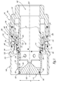
- the male element 100 represented in the state uncoupled to the figure 1 has a generally tubular structure centered on an axis XX.
- a radial direction or all that is characterized radially refers to a direction perpendicular to the axis XX.
- the body 101 of this male element 100 comprises a piston 102 and a structure 104 which respectively constitute the inner and outer parts of the body 101 of the male element 100.
- the piston 102 comprises a generally conical portion 106 and a generally cylindrical portion 108, both are substantially centered on the axis XX.
- the conical portion 106 of the piston 102 is situated at the front of the male element 100, that is to say turned, during coupling, to a complementary element of the connection to which the male element 100 belongs.
- conical portion 106 and the cylindrical portion 108 of the piston 102 form a single block.
- the cylindrical portion 108 defines an internal fluid flow channel 162 in the connecting member 100 and has in its forward end portion, that is to say in contact with the conical portion 106, openings 207 in which the fluid can flow when the fitting is coupled.
- the conical portion 106 has an outer radial surface 107 while the cylindrical portion 108 of the piston 102 has an outer radial surface 109, having a peripheral hollow housing 114.
- the body 101 of the male member 100 is formed of a single block, the piston 102 and the external structure 104 being connected by a rear end portion 110 of the body 101, the flow channel 162 being connected to a pipe not shown at the rear end portion 110.
- the outer structure 104 thus extends from this rear end portion 110 to the front end portion of the body 101, the same axial level of which is substantially located the conical portion 106 piston 102.
- a generally tubular sealing ring 120 is disposed radially between the piston 102 and the outer portion 104.
- a first seal 123, housed at the outer radial surface 107 is disposed radially between the sealing ring 120 and the tapered portion 106 of the piston 102 and a second seal 124, housed at the outer radial surface 109, at the front of the hollow peripheral housing 114, is disposed radially between the cylindrical portion 108 of the piston 102 and the sealing ring 120, which ensures a sealed overlap of the piston 102 at the openings 207 by the sealing ring 120 in uncoupled configuration and thus the closure of the flow channel 162 and the pipe connected to the element connection 100.
- a shoulder 125 is defined, resulting in a narrowing of the diameter of the seal ring forward. Note a first planar face 126 of the sealing ring 120, as the front axial end. In the same way, a second planar face 113 is noted as the forward axial end of the piston 102.
- the shoulder 125 also has an inner surface 128 and an outer surface 129.
- the sealing ring 120 has, in its portion substantially at the same axial level as the seal 123 an internal diameter ⁇ 1 and, in its portion substantially at the same axial level as the seal 124, an inside diameter ⁇ 2.
- ⁇ 1 and ⁇ 2 are the sealing diameters of the sealing ring 120 with the piston 102 in uncoupled configuration.
- ⁇ 1 is strictly less than ⁇ 2 for example of the order of 0.15 mm: this has the advantage, in the presence of a fluid under pressure inside the sealing ring, to press the sealing ring 120 forwardly in abutment against a shoulder 117 of the piston 102. Indeed, the pressure of the fluid on the inner surface of the sealing ring 120, in particular at the surface 128 of the shoulder 125 tends to maintain the closing the male element 100.
- the cylindrical portion 108 of the piston 102 also comprises radial through holes 116 distributed around the axis XX and arranged axially at the front with respect to the seal 124 and at the rear relative to the openings 207 on a portion of the piston 102 which the outside diameter is smaller than the diameter ⁇ 2.
- the pair of plane faces 126 and 113 are planar faces flush with each other. This cleverly allows to limit fluid residues.
- the sealing ring 120 is movable along the axis XX relative to the piston 102 during coupling and uncoupling and carries a coupling member 130. This coupling member 130 is movable radially relative to the ring. sealing device and comprises or consists of hitch balls 131.
- 12 coupling balls are housed and radially movable in respective cylindrical housings 115 formed in the sealing ring 120 around of the axis XX and, in the uncoupled configuration, are partially arranged in the hollow housing 114 of the cylindrical portion 108 of the piston 102.
- a memory ring 142 is disposed radially between the sealing ring 120 and the outer portion 104 of the male body 101.
- a spring 144 is interposed between the sealing ring 120 and the memory ring 142 along the axis XX and pushes the ring memory 142 towards the front of the connecting element 100 and abutting against a shoulder 103 of the sealing ring 120.
- the memory ring 120 In uncoupled configuration, the memory ring 120, then abutting against the shoulder 103, radially covers the balls coupling 131 housed both in the cylindrical housings 115 and in the hollow housing 114, where they are locked, in axial cooperation with the piston 102, for coupling the body 101 and the sealing ring 120, in other words to axially, in close clearance, the body 101 and the sealing ring 120.
- the hitching of the body 101 with the sealing ring 120 ensures the sealed covering of the piston 102 by the sealing ring 120.
- the male element 100 also comprises a locking device 150.
- This locking device 150 comprises both a locking ring 152, arranged externally to the external structure 104 of the body 101 of the connecting element 100, locking balls 154 , which are housed radially movable in cylindrical housings 119 of the outer structure 104 of the body 101, and a locking spring 156 which is interposed axially between the outer portion 104 of the body 101 and the locking ring 152 to axially push the locking ring 152 towards the front of the connecting element 100, in the radial overlap position of the locking balls 154.
- the locking balls 154 are arranged radially between the memory ring 142 and the locking ring 152
- the memory ring 142 cooperates with the locking balls 154 protruding radially outwardly of the ext structure. As shown in Fig. 104, this causes the locking ring 152 to move backwards against the locking spring 156, thereby locking the locking device 150 in the unlocked position.
- the internal radial surface 141 of the memory ring 142 which has a diameter ⁇ 3, covers the coupling balls 131 while the outer radial surface 143 of the memory ring 142 covers the locking balls 154.
- a protection ring 105 is defined as a front end portion of the outer structure 104 of the male element 100. This ring protection 105 thus advantageously makes it possible to protect the outer surface of the sealing ring 120 in the event of impact and limits accessibility to the memory ring 142.
- a visual indicator 160 is also positioned externally on the external structure 104 of the body 101 of the male element 100 and is discovered by the locking ring 152 in uncoupled configuration.
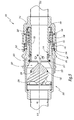
- a complementary coupling element 200 which in the example under consideration is a female element, in the uncoupled configuration.
- This female element 200 has a generally tubular shape about an axis YY and comprises an outer portion 202 which constitutes the body of the female element and a valve 204.
- the outer portion 202 is connected to a pipe not shown.
- the valve 204 closes an opening O1.
- a spring 206 bears on the valve 204 and on the body 202 of the female element, parallel to the axis YY and pushes the valve 204 forward of the body 202 in the closed position against the body 202.
- the body 202 of the female element 200 has on its outer surface 208 a peripheral hollow housing 210 and, on its inner surface 212, a shoulder 214 having an inner surface 215 and widening towards the front, as well as a peripheral hollow housing 216 disposed axially at the front relative to the housing 210 and the shoulder 214.
- the front end of the body 202 of the female element that is to say turned towards the element male 100 during coupling has a minimum inside diameter ⁇ 6, disposed at the front of the hollow housing 216.
- a seal 217 is housed in the body 202 at the opening O1, and arranged radially between the valve 204 and the body of the female element 202.
- the figure 3 represents an intermediate position of the coupling between the male element 100 and the female element 200, the axes XX and YY being then merged forming a coupling axis.
- the body 202 of the female element 200 is brought around the sealing ring 120 and comes into axial contact with the memory ring 142, thus pushing it towards the rear of the body 101 against the spring 144.
- the mating force implemented directly combat axial forces related to the elastic force of the spring 206 of the valve 204, the friction force of the seal 217 of the valve 204 and the elastic force of the spring memory 144.
- the memory ring 142 in cooperation with the body 202, then shifts axially relative to the balls coupling 131 and stops blocking them in the hollow housing 114.
- the body 202 of the female element 200 then comes into contact with the sealing ring 120 by abutment between the inner surface 215 of the shoulder 214 of the body 202 of the female element 200 and the outer surface 129 of the shoulder 125 of the sealing ring 120.
- the seal is then operative between the sealing ring 120 and the female body 202 via the seal 217, the same as between the sealing ring 120 and the piston 102 via the seal 124.
- the piston 102 pushing the valve 204 towards the rear of the body 202 against the spring valve 206, the valve 204 away from the male element.
- the hollow housing 216 reaches radially opposite the coupling balls 131 and the progression of the female element 200 in the coupling direction sets in axial translation, towards the rear of the connecting element 100, the sealing ring 120.
- the coupling balls 131 being released from the cover of the memory ring 142, and facing the housings 216, progress with the sealing ring 120 towards the rear of the connecting element 100 and are radially driven out of the inner housing. 114 of the outer surface of the piston 102 to the hollow housing 216 of the female body 202, thereby passing the connector into the configuration of the figure 4 , where the coupling balls 131 are partially engaged in the hollow housing 216 and the seal is broken between the sealing ring 120 and the piston 102, more particularly at the seal 123.
- the sealing ring 120 is in an open position in which the fluid can flow in the connection between the two elements of the fitting.
- the spring 144 is interposed between the sealing ring 120 and the memory ring 142, so that as soon as the sealing ring 120 is pushed back by the body 202 of the female element 200, the operator no longer has to fight against the elastic force of the spring 144 to continue the coupling. The operator must however combat the friction forces of the seals 123, 124 and the elastic force of the spring 206, then, as soon as the fluid flows in the connection, only the friction of the seal 124 and the effort resilient spring 206.
- the coupling member 130 for coupling the piston 102 and the sealing ring 120 in uncoupled configuration successively fulfills another function which is the axial connection of the sealing ring 120 with the body of the female element 202.
- each coupling ball 131 housed in a housing 115, which is respectively in a first position engaged in the housing 114 of the piston 102 and goes into a second position engaged in the housing 216 of the body of the female element 202.
- the external surface 109 of the piston 102 at the rear of the housing 114, radially covers the coupling balls 131 in the cylindrical housings 115, engaged in the housing 216.
- the coupling balls 131 are then locked in axial cooperation with the body 202 axially solidarisant the sealing ring 120 and the body 202.
- the housing 210 located on the outer surface 212 of the female element 200 is positioned in radial alignment with the locking balls 154.
- the locking balls 154 are then pushed by the locking ring 152, in the locked position in the housing 210 provided for this purpose.
- the locking ring 152 driven by the locking spring 156, then comes into locked position externally cover the locking balls 154: the body 101 is axially locked with the body 202 and the coupling is coupled.
- the coupling balls 131 are always locked by the outer radial surface 109 in their second position of axial connection of the sealing ring 120 with the body 202.
- the body 101 of the connecting element 100 therefore allows the coupling balls to be locked in their second position while the sealing ring 120 moves between the closed position and the open position.
- the visual indicator 160 is then no longer visible because covered by the locking ring 152 as shown figure 5 in coupled configuration. This visual indicator 160 therefore makes it possible to testify whether the system is locked or not.
- the memory ring 142 thus serves both during the coupling, to successively discover in this order the coupling balls 131 and the locking balls 154.
- the memory ring 142 can be replaced by two separate parts respectively assuming the locking function in connection with the coupling member 130 and the memory function in connection with the locking device. locking 150.
- the coupling of the sealing ring 120 with the female body 202 by the coupling balls 131 makes it possible to open the circuit safely before locking the coupling. Indeed, in the case where the coupling would be interrupted before locking the connector, by removing the element 200 out of the male element 100, the circuit would be closed again without risk of leakage since the withdrawal of the female body 202 would jointly cause the withdrawal of the sealing ring 120. This until the sealing ring is disengaged from the female body 202 and is held axially with the piston 102, thus ensuring a sealed covering thereof.
- the memory ring 142 acting on the locking balls 154, ensures an automatic coupling, that is to say under the sole action of fitting the body 202 in the connecting member 100, without recoil of the locking ring 152 and with axial mating forces minimized.
- the sealing ring 120 comes, in the continuation of its movement, covering the cylindrical portion 108 of the piston 102.
- the sealing ring 120 is then able to cause in its movement of the fluid, which can remain trapped between the inner surface the sealing ring, at the inner surface 128, and the outer radial surface of the cylindrical portion 108 of the piston 102, overlapping the front of the seal 124.
- the radial through holes 116 then allow to evacuate these possible fluid residues towards the inside of the piston 102.
- the sealing ring 120 guarantees the tightness of the connection of the two connecting elements 100 and 200 by cooperating with the seal 217 and the seal 124.
- the sealing diameter ⁇ 5 of the sealing ring 120 with the body 202 at the joint 217, corresponding to the outer diameter of the sealing ring 120 in contact with the seal 217, is strictly less than the sealing diameter ⁇ 2 of the sealing ring 120 with the body 101, at the joint 124, corresponding to the inside diameter of the sealing ring in contact with the seal 124, the differential being of the order of 0.15 mm.
- the force of the circulating fluid tends to push the sealing ring 120 towards the front of the connecting element 100, in contact with the body 202, so that the coupling balls 131 do not undergo any damage. Efforts related to fluid pressure.
- the operator When uncoupling, the operator is asked to unlock the connector first, pulling back on the locking ring 154, thus revealing the visual locking indicator 160 and leaving a radial clearance clearance to the outside for the locking balls 154.
- the user compresses the locking spring 156 intended to return the locking ring by overlapping the locking balls 154.
- the user By removing the body 202 of the female element 200 from the male element 100, the user pushes back radially outwardly the locking balls 154 which protrude from the housing 210 and drives, by means of the coupling balls 131 held in the housing 216 of the inner surface 212 of the body 202 of the female element 200, the ring 120.
- the memory ring 142 driven integrally of the sealing ring 120 and pushed by the spring 144, is inserted under the locking balls 154, blocking the locking device 150 in the unlocked position. Then, the coupling balls 131 radially reach the hollow housing 114 of the cylindrical portion 108 of the piston 102 with the sealing ring 120 abutting against the shoulder 117 of the piston 102. The coupling balls 131 then cease to solidify. axially the sealing ring 120 and the body 202 of the female member 200 while the sealing ring 120 has sealed the piston 102 and thus interrupted the flow of fluid.
- the memory ring 142 pushed by the spring 144 then intelligently covers the coupling balls 131 in the housing 114 to maintain the sealing ring 120 in the closed position of the flow channel 162.
- the spring 144 is just sized to push the memory in the overlap position of the coupling balls 131 and the locking balls 154.
- this spring 144 is not dimensioned according to the friction induced by the joints 123, 124 and 217 under pressure, the elastic force of the spring 144 is substantially less than the friction forces of the joints 123, 124 and 217.
- the internal diameter ⁇ 6 of the body 202 of the female element 200 is provided strictly less than the internal diameter ⁇ 3 of the memory ring 142.
- the memory ring 140 has a radial clearance with the cylindrical housings 115 of the balls coupling 131 greater than the radial clearance, the front end of the body 202 of the female element 200 has with the cylindrical housings 115. This advantageously allows to facilitate the movement of the memory ring 142, under the sole effort resilient spring 144, limiting friction when the inner surface of minimum diameter ⁇ 6 shifts relative to the coupling balls 131 during uncoupling and the internal surface diameter ⁇ 3 comes in radial overlap coupling balls 131.
- the memory ring 142 has already covered the locking balls 154 when it must cover the coupling balls 131 in the hollow housing 114. This decoupling makes it possible to minimize the elastic force of the spring 144.
- the coupling of the sealing ring 120 with the female body 202 by the coupling balls 131 throughout the displacement of the sealing ring 120 relative to the body 101 as well as the coupling of the sealing ring 120 with the body 101 uncoupled configuration allow to suppress the elastic return of the sealing ring 120 in the closed position relative to the body 101 and thus to reduce the connection forces, compared to the connection of the state of the 'art.
Landscapes
- Engineering & Computer Science (AREA)
- General Engineering & Computer Science (AREA)
- Mechanical Engineering (AREA)
- Quick-Acting Or Multi-Walled Pipe Joints (AREA)
Description
- L'invention concerne un raccord constitué d'un élément de raccord et d'un élément de raccord complémentaire aptes à s'accoupler. En particulier, il peut être considéré que l'élément de raccord est un élément mâle et l'élément de raccord complémentaire est un élément femelle étant entendu que l'inverse est envisageable.
- A titre d'exemple, l'invention a pour application un raccord fluidique pour gros passages dont le diamètre est supérieur à 20 mm. Une application potentielle est par exemple un raccord de remplissage pour un liquide réfrigérant.
- Il est connu que pour les raccords avec gros passages, les joints d'étanchéité ayant un diamètre important, les efforts dus aux frottements lors des phases d'accouplement et de désaccouplement sont des efforts importants. Des ressorts intégrés au raccord sont alors dimensionnés pour accompagner le rappel des pièces soumises à ces efforts de frottement comme la soupape en position de fermeture. Il en résulte que, lors de la phase d'accouplement, l'opérateur doit exercer un effort important pour, d'une part, compenser les efforts de frottement liés aux joints et, d'autre part, comprimer les ressorts.
- Par ailleurs,
US-A-2009/0224534 , sur lequel est basé le préambule de la revendication 1, divulgue un raccord de passage d'air comprimé. Ce raccord comprend un élément de raccord destiné à être connecté avec un élément de raccord complémentaire. L'élément de raccord comporte un bâti, un manchon qui est vissé à l'intérieur du bâti, une bague d'étanchéité qui est disposée coaxialement à l'intérieur du manchon et un piston. On définit un corps de l'élément de raccord formé par le bâti et le manchon. La bague d'étanchéité est pourvue d'évidements de passage de l'air comprimé. En configuration désaccouplée, la bague d'étanchéité est dans une position d'obturation où les évidements sont bouchés par le manchon si bien qu'il n'y a pas de passage d'air dans le raccord. Durant l'accouplement, la bague d'étanchéité se déplace axialement vers une position d'ouverture où l'air peut circuler dans les évidements. En position d'obturation, la bague d'étanchéité est attelée au corps de l'élément de raccord par l'intermédiaire de billes qui sont logées, d'une part, dans des trous traversants de la bague d'étanchéité et, d'autre part, dans des trous oblongs du manchon. Autour du manchon est disposé un anneau de verrouillage qui est mobile autour du corps et soumis à un effort de charge élastique en direction de l'extrémité avant de l'élément de raccord. En position d'obturation de la bague d'étanchéité, l'anneau de verrouillage maintient les billes pour la solidarisation axiale entre le manchon et la bague d'étanchéité. Cet anneau est apte à recouvrir les billes et à les bloquer en coopération avec l'élément de raccord complémentaire, pour solidariser axialement le corps de l'élément de raccord complémentaire avec la bague d'étanchéité en cours d'accouplement et de désaccouplement. - Le fait de bloquer les billes d'attelage par l'anneau de verrouillage ne fiabilise pas la solidarisation axiale de la bague d'étanchéité avec le corps de l'élément de raccord complémentaire en cours d'accouplement et de désaccouplement. Pour cette raison, le raccord utilise un ressort de rappel de la bague d'étanchéité vers une configuration d'obturation du raccord, ce qui complexifie le montage du raccord et augmente les efforts d'accouplement. Ce ressort est disposé au sein du canal fluidique et son fonctionnement risque d'être altéré par la pression de l'air comprimé circulant dans le raccord.
- C'est à cet inconvénient qu'entend plus particulièrement remédier l'invention en proposant un raccord dont la connexion s'effectue de manière plus fiable et avec moins d'efforts d'accouplement et qui reste simple.
- A cet effet l'invention concerne un raccord fluidique tel que défini à la revendication 1.
- Grâce à l'invention, en configuration désaccouplée, l'organe d'attelage, bloqué par l'organe de blocage, permet de maintenir la bague d'étanchéité dans cette position d'obturation étanche du corps de l'élément de raccord. Alors qu'au cours de l'accouplement et du désaccouplement, le même organe d'attelage, libéré du recouvrement de la bague de blocage, permet d'atteler la bague d'étanchéité au corps de l'élément de raccord complémentaire pour solidariser axialement leurs mouvements. La bague d'étanchéité n'a donc pas à être repoussée élastiquement vers sa position d'obturation et les efforts d'accouplement sont donc réduits. L'invention reste simple, dans le sens où un même organe d'attelage coopère axialement à la fois avec le corps de l'élément de raccord et le corps de l'élément de raccord complémentaire. On comprend que la coopération de l'organe d'attelage avec l'élément de raccord et celle avec l'élément de raccord complémentaire sont deux opérations distinctes et successives. En effet, en configuration désaccouplée, l'organe d'attelage est apte à solidariser axialement la bague d'étanchéité avec le corps de l'élément de raccord, puis dans un deuxième temps, lors de l'accouplement et du désaccouplement, l'organe d'attelage, alors désuni du corps de l'élément de raccord, permet d'atteler la bague d'étanchéité au corps de l'élément de raccord complémentaire. En outre, le rappel de la bague d'étanchéité en position d'obturation ne s'effectue pas au moyen d'un ressort central disposé au sein du canal fluidique. Enfin, le fait de bloquer l'organe d'attelage par le corps de l'élément de raccord dans la deuxième position fiabilise davantage la solidarisation axiale entre la bague d'étanchéité et le corps de l'élément de raccord complémentaire.
- Des aspects avantageux mais non obligatoires de l'invention sont spécifiés aux revendications 2 à 12.
- L'invention sera mieux comprise et d'autres avantages de celle-ci apparaîtront plus clairement à la lumière de la description qui va suivre d'un mode de réalisation d'un raccord conforme à son principe, donnée uniquement à titre d'exemple et faite en référence aux dessins annexés dans lesquels :
- la
figure 1 est une coupe longitudinale d'un élément mâle appartenant à un raccord conforme à l'invention, - la
figure 2 est une coupe longitudinale d'un élément femelle appartenant au raccord conforme à l'invention, - les
figures 3 à 5 sont des coupes longitudinales du raccord, montrant trois configurations d'accouplements distinctes et successives. - Dans le mode de réalisation décrit ci-dessous, l'arrivée du fluide peut se faire indifféremment côté élément mâle ou côté élément femelle.
- L'élément mâle 100 représenté à l'état désaccouplé à la
figure 1 présente une structure globalement tubulaire centrée sur un axe X-X. Dans la suite de la description, une direction radiale ou tout ce qui est caractérisé radialement fait référence à une direction perpendiculaire à l'axe X-X. Le corps 101 de cet élément mâle 100 comporte un piston 102 et une structure 104 qui constituent respectivement les parties interne et externe du corps 101 de l'élément mâle 100. Le piston 102 comprend une partie globalement conique 106 et une partie globalement cylindrique 108, toutes les deux sensiblement centrées sur l'axe X-X. La partie conique 106 du piston 102 est située à l'avant de l'élément mâle 100, c'est-à-dire tournée, en cours d'accouplement, vers un élément complémentaire du raccord auquel appartient l'élément mâle 100. La partie conique 106 et la partie cylindrique 108 du piston 102 forment un seul bloc. La partie cylindrique 108 délimite un canal interne d'écoulement du fluide 162 dans l'élément de raccord 100 et présente dans sa partie terminale avant, c'est-à-dire en contact avec la partie conique 106, des ouvertures 207 dans lesquelles le fluide peut circuler lorsque le raccord est accouplé. La partie conique 106 présente une surface radiale externe 107 tandis que la partie cylindrique 108 du piston 102 présente une surface radiale externe 109, comportant un logement creux périphérique 114. Le corps 101 de l'élément mâle 100 est formé d'un seul bloc, le piston 102 et la structure externe 104 étant reliés par une partie terminale arrière 110 du corps 101, le canal d'écoulement 162 étant raccordé à une canalisation non représentée au niveau de la partie terminale arrière 110. La structure externe 104 s'étend donc de cette partie terminale arrière 110 jusqu'à la partie terminale avant du corps 101, au même niveau axial de laquelle est sensiblement située la partie conique 106 du piston 102. - Une bague d'étanchéité 120 de forme globalement tubulaire est disposée radialement entre le piston 102 et la partie externe 104. Un premier joint d'étanchéité 123, logé au niveau de la surface radiale externe 107 est disposé radialement entre la bague d'étanchéité 120 et la partie conique 106 du piston 102 et un deuxième joint d'étanchéité 124, logé au niveau de la surface radiale externe 109, à l'avant du logement périphérique creux 114, est disposé radialement entre la partie cylindrique 108 du piston 102 et la bague d'étanchéité 120, ce qui assure un recouvrement étanche du piston 102 au niveau des ouvertures 207 par la bague d'étanchéité 120 en configuration désaccouplée et donc l'obturation du canal d'écoulement 162 et de la canalisation reliée à l'élément de raccord 100.
- On définit un épaulement 125, donnant lieu à un rétrécissement du diamètre de la bague d'étanchéité vers l'avant. On note une première face plane 126 de la bague d'étanchéité 120, comme l'extrémité axiale avant. De la même manière, on note une deuxième face plane 113 comme l'extrémité axiale avant du piston 102. L'épaulement 125 présente également une surface interne 128 et une surface externe 129.
- La bague d'étanchéité 120 présente, dans sa partie sensiblement située au même niveau axial que le joint d'étanchéité 123 un diamètre intérieur Φ1 et, dans sa partie sensiblement située au même niveau axial que le joint d'étanchéité 124, un diamètre intérieur Φ2. Φ1 et Φ2 sont les diamètres d'étanchéité de la bague d'étanchéité 120 avec le piston 102 en configuration désaccouplée. Φ1 est strictement inférieur à Φ2 par exemple de l'ordre de 0,15 mm : ceci a pour avantage, en présence d'un fluide sous pression à l'intérieur de la bague d'étanchéité, de plaquer la bague d'étanchéité 120 vers l'avant en butée contre un épaulement 117 du piston 102. En effet, la pression du fluide sur la surface interne de la bague d'étanchéité 120, notamment au niveau de la surface 128 de l'épaulement 125 tend à maintenir l'obturation de l'élément mâle 100.
La partie cylindrique 108 du piston 102 comporte également des trous traversants radiaux 116 répartis autour de l'axe X-X et disposés axialement à l'avant par rapport au joint 124 et à l'arrière par rapport aux ouvertures 207 sur une partie du piston 102 dont le diamètre extérieur est inférieur au diamètre Φ2. Le couple de faces planes 126 et 113 sont des faces planes affleurantes l'une avec l'autre. Ceci permet astucieusement de limiter les résidus de fluide.
La bague d'étanchéité 120 est mobile selon l'axe X-X par rapport au piston 102 au cours de l'accouplement et du désaccouplement et porte un organe d'attelage 130. Cet organe d'attelage 130 est mobile radialement par rapport à la bague d'étanchéité et comporte, voire se compose de billes d'attelage 131. En l'occurrence, dans cet exemple, 12 billes d'attelage sont logées et mobiles radialement dans des logements cylindriques 115 respectifs ménagés dans la bague d'étanchéité 120 autour de l'axe X-X et, dans la configuration désaccouplée, sont partiellement disposées dans le logement creux 114 de la partie cylindrique 108 du piston 102. - Une bague mémoire 142 est disposée radialement entre la bague d'étanchéité 120 et la partie externe 104 du corps mâle 101. Un ressort 144 est intercalé entre la bague d'étanchéité 120 et la bague mémoire 142 selon l'axe X-X et repousse la bague mémoire 142 vers l'avant de l'élément de raccord 100 et en butée contre un épaulement 103 de la bague d'étanchéité 120. En configuration désaccouplée, la bague mémoire 120, alors en butée contre l'épaulement 103, recouvre radialement les billes d'attelage 131 logées à la fois dans les logements cylindriques 115 et dans le logement creux 114, où elles sont bloquées, en coopération axiale avec le piston 102, afin d'atteler le corps 101 et la bague d'étanchéité 120, autrement dit, de solidariser axialement, aux jeux près, le corps 101 et la bague d'étanchéité 120. L'attelage du corps 101 avec la bague d'étanchéité 120 assure le recouvrement étanche du piston 102 par la bague d'étanchéité 120.
- L'élément mâle 100 comprend également un dispositif de verrouillage 150. Ce dispositif de verrouillage 150 comprend à la fois une bague de verrouillage 152, disposée extérieurement à la structure externe 104 du corps 101 de l'élément raccord 100, des billes de verrouillage 154, qui sont logées de façon radialement mobile dans des logements cylindriques 119 de la structure externe 104 du corps 101, et un ressort de verrouillage 156 qui est intercalé axialement entre la partie externe 104 du corps 101 et la bague de verrouillage 152 pour repousser axialement la bague de verrouillage 152 vers l'avant de l'élément de raccord 100, en position de recouvrement radial des billes de verrouillage 154. En configuration désaccouplée, les billes de verrouillage 154 sont disposées radialement entre la bague mémoire 142 et la bague de verrouillage 152. La bague mémoire 142 coopère avec les billes de verrouillage 154 qui dépassent radialement vers l'extérieur de la structure externe 104, repoussant ainsi la bague de verrouillage 152 en position arrière à l'encontre du ressort de verrouillage 156, et bloque donc le dispositif de verrouillage 150 en position déverrouillée. Avec la bague mémoire 142 repoussée par le ressort 144 en configuration désaccouplée du raccord, la surface radiale interne 141 de la bague mémoire 142, qui présente un diamètre Φ3, recouvre les billes d'attelage 131 tandis que la surface radiale externe 143 de la bague mémoire 142 recouvre les billes de verrouillage 154. On définit une bague de protection 105 comme une partie terminale avant de la structure externe 104 de l'élément mâle 100. Cette bague de protection 105 permet donc avantageusement de protéger la surface externe de la bague d'étanchéité 120 en cas de choc et limite l'accessibilité à la bague mémoire 142.
- Un témoin visuel 160 est également positionné extérieurement sur la structure externe 104 du corps 101 de l'élément mâle 100 et est découvert par la bague de verrouillage 152 en configuration désaccouplée.
- Sur la
figure 2 est représenté un élément de raccord complémentaire 200, qui dans l'exemple considéré, est un élément femelle, dans la configuration désaccouplée. Cet élément femelle 200 présente une forme globalement tubulaire autour d'un axe Y-Y et comprend une partie externe 202 qui constitue le corps de l'élément femelle et une soupape 204. La partie externe 202 est reliée à une canalisation non-représentée. Dans la configuration désaccouplée du raccord, la soupape 204 obture une ouverture O1. Un ressort 206 prend appui sur la soupape 204 et sur le corps 202 de l'élément femelle, parallèlement à l'axe Y-Y et repousse la soupape 204 vers l'avant du corps 202 en position de fermeture contre le corps 202. - Par ailleurs, le corps 202 de l'élément femelle 200 présente sur sa surface externe 208 un logement creux périphérique 210 et, sur sa surface interne 212, un épaulement 214 ayant une surface interne 215 et s'élargissant vers l'avant, ainsi qu'un logement creux périphérique 216, disposé axialement à l'avant par rapport au logement 210 et à l'épaulement 214. L'extrémité avant du corps 202 de l'élément femelle, c'est-à-dire tournée vers l'élément mâle 100 en cours d'accouplement présente un diamètre intérieur minimal Φ6, disposé à l'avant du logement creux 216. Un joint d'étanchéité 217 est logé dans le corps 202 au niveau de l'ouverture O1, et disposé radialement entre la soupape 204 et le corps de l'élément femelle 202.
- La
figure 3 représente une position intermédiaire de l'accouplement entre l'élément mâle 100 et l'élément femelle 200, les axes X-X et Y-Y étant alors confondus en formant un axe d'accouplement. Le corps 202 de l'élément femelle 200 est amené autour de la bague d'étanchéité 120 et vient axialement en contact de la bague mémoire 142, la repoussant ainsi vers l'arrière du corps 101 à l'encontre du ressort 144. L'effort d'accouplement mis en oeuvre combat directement des efforts axiaux liés à l'effort élastique du ressort 206 de la soupape 204, à l'effort de frottement du joint d'étanchéité 217 de la soupape 204 et à l'effort élastique du ressort mémoire 144. La bague mémoire 142, en coopération avec le corps 202, se décale alors axialement par rapport aux billes d'attelage 131 et cesse de les bloquer dans le logement creux 114. Le corps 202 de l'élément femelle 200 vient ensuite au contact de la bague d'étanchéité 120 par butée entre la surface interne 215 de l'épaulement 214 du corps 202 de l'élément femelle 200 et la surface externe 129 de l'épaulement 125 de la bague d'étanchéité 120. L'étanchéité est alors opérationnelle entre la bague d'étanchéité 120 et le corps femelle 202 par l'intermédiaire du joint 217, au même titre qu'entre la bague d'étanchéité 120 et le piston 102 par l'intermédiaire du joint d'étanchéité 124. En revanche, le piston 102 repoussant la soupape 204 vers l'arrière du corps 202 à l'encontre du ressort de soupape 206, la soupape 204 s'éloigne donc de l'élément mâle . Simultanément, le logement creux 216 parvient radialement en regard des billes d'attelage 131 et la progression de l'élément femelle 200 dans le sens de l'accouplement met en translation axiale, vers l'arrière de l'élément de raccord 100, la bague d'étanchéité 120. - Les billes d'attelage 131 étant libérées du recouvrement de la bague mémoire 142, et se retrouvant face aux logements 216, progressent avec la bague d'étanchéité 120 vers l'arrière de l'élément de raccord 100 et sont radialement chassées du logement interne 114 de la surface externe du piston 102 vers le logement creux 216 du corps femelle 202, passant ainsi le raccord dans la configuration de la
figure 4 , où les billes d'attelage 131 sont partiellement engagées dans le logement creux 216 et l'étanchéité est rompue entre la bague d'étanchéité 120 et le piston 102, plus particulièrement au niveau du joint d'étanchéité 123. La bague d'étanchéité 120 se trouve dans une position d'ouverture dans laquelle le fluide peut circuler dans le raccord entre les deux éléments du raccord. - De manière avantageuse, le ressort 144 est intercalé entre la bague d'étanchéité 120 et la bague mémoire 142, si bien que dès lors que la bague d'étanchéité 120 est repoussée par le corps 202 de l'élément femelle 200, l'opérateur n'a plus à lutter contre l'effort élastique du ressort 144 pour poursuivre l'accouplement. L'opérateur doit en revanche combattre les efforts de frottements des joints d'étanchéité 123, 124 et l'effort élastique du ressort 206, puis, dès que le fluide circule dans le raccord, uniquement les frottements du joint 124 ainsi que l'effort élastique du ressort 206.
- L'organe d'attelage 130 permettant d'atteler le piston 102 et la bague d'étanchéité 120 en configuration désaccouplée remplit successivement une autre fonction qui est la solidarisation axiale de la bague d'étanchéité 120 avec le corps de l'élément femelle 202, aux jeux près, lorsque celle-ci se déplace par rapport au corps 101, ceci avec chaque bille d'attelage 131, logée dans un logement 115, qui se trouve respectivement dans une première position en prise dans le logement 114 du piston 102 puis passe dans une seconde position en prise dans le logement 216 du corps de l'élément femelle 202. En particulier, comme bien visible sur la
figure 4 , la surface externe 109 du piston 102, à l'arrière du logement 114, recouvre radialement les billes d'attelage 131 dans les logements cylindriques 115, en prise dans le logement 216. Les billes d'attelage 131 sont alors bloquées en coopération axiale avec le corps 202 solidarisant axialement la bague d'étanchéité 120 et le corps 202. - Il est à noter qu'au début du mouvement de la bague d'étanchéité 120 sous l'action du corps 202 en cours d'accouplement, les billes d'attelage 131 solidarisent axialement la bague d'étanchéité 120 et le corps 202 alors même que l'étanchéité est encore opérationnelle au niveau du joint 123.
- Depuis la configuration intermédiaire de la
figure 4 , la poursuite de l'accouplement de l'élément femelle 200 avec l'élément mâle 100 consiste à ce que le corps 202 de l'élément femelle 200 continue d'entraîner dans son mouvement de translation la bague d'étanchéité 120 et la bague mémoire 142 jusqu'à ce que la bague d'étanchéité 120 atteigne une butée de fin de course 220 qui représente la zone de contact entre l'extrémité arrière de la bague d'étanchéité 120 et le corps 101 de l'élément mâle 100 , le raccord étant alors sensiblement dans la configuration de lafigure 5 . La bague mémoire 142, repoussée par la corps 202, est alors décalée axialement par rapport aux billes de verrouillage 154 et n'agit plus sur les billes de verrouillage 154. Durant ce mouvement, l'opérateur lutte uniquement contre les efforts de frottements liés au joint d'étanchéité 124, ce qui fait que les efforts fournis par l'opérateur sont plus importants au début de l'accouplement qu'en fin d'accouplement. Par ailleurs, le corps femelle 202, en repoussant axialement la bague mémoire 142, vient s'intercaler entre les billes de verrouillage 154 et la bague d'étanchéité 120. - Le logement 210 situé sur la surface externe 212 de l'élément femelle 200 vient se positionner en regard radial des billes de verrouillage 154. Les billes de verrouillage 154 sont alors repoussées par la bague de verrouillage 152, en position verrouillée dans le logement 210 prévu à cet effet. La bague de verrouillage 152, entrainée par le ressort de verrouillage 156, vient alors en position verrouillée recouvrir extérieurement les billes de verrouillage 154 : le corps 101 est verrouillé axialement avec le corps 202 et le raccord est accouplé.
- En configuration accouplée du raccord, les billes d'attelage 131 sont toujours bloquées par la surface radiale externe 109 dans leur deuxième position de solidarisation axiale de la bague d'étanchéité 120 avec le corps 202. Le corps 101 de l'élément de raccord 100 permet donc de bloquer les billes d'attelage dans leur deuxième position pendant que la bague d'étanchéité 120 se déplace entre la position d'obturation et la position d'ouverture.
- Le témoin visuel 160 n'est alors plus visible, car recouvert par la bague de verrouillage 152 comme représenté
figure 5 en configuration accouplée. Ce témoin visuel 160 permet donc de témoigner si le système est verrouillé ou non. La bague mémoire 142 sert donc à la fois, au cours de l'accouplement, à découvrir successivement dans cet ordre les billes d'attelage 131 et les billes de verrouillage 154. - On comprend donc que, à titre de variante non représentée, la bague mémoire 142 peut être remplacée par deux pièces distinctes assumant respectivement la fonction de blocage en lien avec l'organe d'attelage 130 et la fonction de mémoire en lien avec le dispositif de verrouillage 150. Ainsi, le fait d'utiliser une même pièce pour assurer les fonctions de blocage et de mémoire permet d'obtenir un raccord plus compact.
- L'attelage de la bague d'étanchéité 120 avec le corps femelle 202 par les billes d'attelage 131 permet d'ouvrir le circuit en toute sécurité avant le verrouillage du raccord. En effet, dans le cas où l'accouplement serait interrompu avant le verrouillage du raccord, par le retrait de l'élément 200 hors de l'élément mâle 100, le circuit serait de nouveau obturé sans risque de fuite puisque le retrait du corps femelle 202 entraînerait solidairement le retrait de la bague d'étanchéité 120. Ceci jusqu'à ce que la bague d'étanchéité se désattèle du corps femelle 202 et soit maintenue axialement avec le piston 102, assurant ainsi un recouvrement étanche de celui-ci.
- La bague mémoire 142, agissant sur les billes de verrouillage 154, permet de garantir un accouplement automatique, autrement dit sous la seule action d'emmanchement du corps 202 dans l'élément de raccord 100, sans recul de la bague de verrouillage 152 et avec des efforts axiaux d'accouplement minimisés.
- Pour atteindre la configuration décrite
figure 5 , la bague d'étanchéité 120 vient, dans la poursuite de son mouvement, recouvrir la partie cylindrique 108 du piston 102. La bague d'étanchéité 120 est alors susceptible d'entraîner dans son mouvement du fluide, pouvant rester emprisonné entre la surface interne de la bague d'étanchéité, au niveau de la surface interne 128, et la surface radiale externe de la partie cylindrique 108 du piston 102, en recouvrement à l'avant du joint 124. Les trous traversant radiaux 116 permettent alors d'évacuer ces éventuels résidus de fluide vers l'intérieur du piston 102. - En configuration accouplée, la bague d'étanchéité 120 garantit l'étanchéité du raccordement des deux éléments de raccord 100 et 200 en coopérant avec le joint 217 et le joint 124. Le diamètre d'étanchéité Φ5 de la bague d'étanchéité 120 avec le corps 202 au niveau du joint 217, correspondant au diamètre externe de la bague d'étanchéité 120 au contact du joint 217, est strictement inférieur au diamètre d'étanchéité Φ2 de la bague d'étanchéité 120 avec le corps 101, au niveau du joint 124, correspondant au diamètre intérieur de la bague d'étanchéité en contact avec le joint 124, le différentiel étant de l'ordre de 0,15 mm. Ainsi, l'effort du fluide en circulation tend à repousser la bague d'étanchéité 120 vers l'avant de l'élément de raccord 100, en contact contre le corps 202, si bien que les billes d'attelage 131 ne subissent pas d'efforts liés à la pression du fluide.
- Lors du désaccouplement, l'opérateur est invité à déverrouiller le raccord en premier lieu, en tirant vers l'arrière sur la bague de verrouillage 154, laissant ainsi apparaitre le témoin visuel de verrouillage 160 et laissant un espace radial de dégagement vers l'extérieur pour les billes de verrouillage 154 . Durant cette opération, l'utilisateur comprime le ressort de verrouillage 156 destiné à rappeler la bague de verrouillage en recouvrement des billes de verrouillage 154. En retirant le corps 202 de l'élément femelle 200 de l'élément mâle 100, l'utilisateur repousse radialement vers l'extérieur les billes de verrouillage 154 qui sortent du logement 210 et entraîne, au moyen des billes d'attelage 131 maintenues dans le logement 216 de la surface interne 212 du corps 202 de l'élément femelle 200, la bague d'étanchéité 120. La bague mémoire 142, entrainée solidairement de la bague d'étanchéité 120 et repoussée par le ressort 144, s'insère sous les billes de verrouillage 154, bloquant le dispositif de verrouillage 150 en position déverrouillée. Puis, les billes d'attelage 131 atteignent radialement le logement creux 114 de la partie cylindrique 108 du piston 102 avec la bague d'étanchéité 120 en butée contre l'épaulement 117 du piston 102. Les billes d'attelage 131 cessent alors de solidariser axialement la bague d'étanchéité 120 et le corps 202 de l'élément femelle 200 alors que la bague d'étanchéité 120 a recouvert de manière étanche le piston 102 et interrompu ainsi la circulation du fluide.
- La bague mémoire 142, repoussée par le ressort 144 vient alors de manière intelligente recouvrir les billes d'attelage 131 dans le logement 114 pour maintenir la bague d'étanchéité 120 en position d'obturation du canal d'écoulement 162. Pour cela, le ressort 144 est juste dimensionné pour repousser la mémoire en position de recouvrement des billes d'attelage 131 et des billes de verrouillage 154. Ainsi, ce ressort 144 n'étant pas dimensionné en fonction des frottements induits par les joints 123, 124 et 217 sous pression, l'effort élastique de ce ressort 144 est donc sensiblement inférieur aux efforts de frottements des joints 123, 124 et 217.
- Par ailleurs, le diamètre interne Φ6 du corps 202 de l'élément femelle 200 est prévu strictement inférieur au diamètre interne Φ3 de la bague mémoire 142. Ainsi, la bague mémoire 140 dispose d'un jeu radial avec les logements cylindriques 115 des billes d'attelage 131 supérieur au jeu radial dont l'extrémité avant du corps 202 de l'élément femelle 200 dispose avec les logements cylindriques 115. Ceci permet, de manière avantageuse, de faciliter les déplacements de la bague mémoire 142, sous le seul effort élastique du ressort 144, en limitant ses frottements lorsque la surface interne de diamètre minimal Φ6 se décale par rapport aux billes d'attelage 131 au cours du désaccouplement et que la surface interne de diamètre Φ3 vient en recouvrement radial des billes d'attelage 131.
- On peut noter qu'au cours du désaccouplement, la bague mémoire 142 a déjà recouvert les billes de verrouillage 154 lorsqu'elle doit recouvrir les billes d'attelage 131 dans le logement creux 114. Ce découplage permet de minimiser l'effort élastique du ressort 144.
- L'attelage de la bague d'étanchéité 120 avec le corps femelle 202 par les billes d'attelage 131 tout au long du déplacement de la bague d'étanchéité 120 par rapport au corps 101 ainsi que l'attelage de la bague d'étanchéité 120 avec le corps 101 en configuration désaccouplée permettent de supprimer le rappel élastique de la bague d'étanchéité 120 en position d'obturation par rapport au corps 101 et donc de diminuer les efforts de connexion, par rapport au raccord de l'état de l'art.
- D'autres modes de réalisation de l'invention sont envisageables tels que le fait de remplacer les billes de verrouillage par une ou plusieurs griffes de verrouillage maintenues par une bague de verrouillage. Ce mode de réalisation autorise également la construction d'une bague unique agissant à la fois sur l'organe d'attelage et sur le dispositif de verrouillage.
- On peut également envisager un raccord présentant un dispositif de verrouillage par baïonnette, dans ce cas, le verrouillage du raccord ne nécessite pas de bague agissant sur des organes de verrouillage.
Claims (12)
- Raccord fluidique, comportant un élément de raccord (100) et un élément de raccord complémentaire (200), aptes à s'accoupler l'un à l'autre selon un axe d'accouplement (X-X, Y-Y), l'élément de raccord (100) comprenant :- un corps (101) délimitant un canal d'écoulement du fluide (162) dans l'élément de raccord (100),- un dispositif de verrouillage (150) adapté pour verrouiller axialement le corps (101) de l'élément de raccord (100) avec un corps (202) de l'élément complémentaire lorsque le raccord est en configuration accouplée, et- une bague d'étanchéité (120), qui, en cours d'accouplement et de désaccouplement du raccord, est déplaçable par rapport au corps (101) de l'élément de raccord entre :- une position d'obturation du canal d'écoulement (162) du corps (101) de l'élément de raccord (100) lorsque le raccord est en configuration désaccouplée, et- une position d'ouverture dans laquelle le fluide peut circuler dans le raccord,cette bague d'étanchéité (120) comprenant un logement (115) de réception d'un organe d'attelage (131) dans lequel l'organe d'attelage (131) est mobile entre :- une première position, dans laquelle l'organe d'attelage (131) solidarise axialement le corps (101) de l'élément de raccord (100) avec la bague d'étanchéité (120) en position d'obturation, et- une deuxième position, dans laquelle l'organe d'attelage (131) solidarise axialement le corps (202) de l'élément de raccord complémentaire (200) avec la bague d'étanchéité (120) en position d'ouverture,- un organe de blocage (142) qui est adapté pour bloquer l'organe d'attelage (131) dans sa première position et pour coopérer avec le corps (202) de l'élément de raccord complémentaire (200), en cours d'accouplement du raccord, pour autoriser le passage de l'organe d'attelage (131) de ladite première à ladite deuxième position,
ce raccord étant caractérisé en ce que, en cours d'accouplement et de désaccouplement du raccord, le corps (101) de l'élément de raccord (100) est apte à bloquer l'organe d'attelage (131) dans ladite deuxième position pendant que la bague d'étanchéité (120) se déplace, entre la position d'obturation et une position d'ouverture dans laquelle le dispositif de verrouillage (150) verrouille axialement le corps (202) de l'élément de raccord complémentaire (200) par rapport au corps (101) de l'élément de raccord (100) - Raccord suivant la revendication 1, caractérisé en ce que le corps (101) de l'élément de raccord (100) comprend un piston (102) interne et une partie de corps externe (104), radialement entre lesquels sont disposés la bague d'étanchéité (120) et l'organe de blocage (142), et en ce que le corps (202) de l'élément de raccord complémentaire (200) est mis en place autour de la bague d'étanchéité (120) en cours d'accouplement et de désaccouplement du raccord.
- Raccord suivant la revendication 2, caractérisé en ce que le corps (202) de l'élément de raccord complémentaire (200) présente un logement creux interne (216) qui reçoit l'organe d'attelage (131) lorsque l'organe d'attelage (131) est dans sa deuxième position, et un logement creux externe (210) qui reçoit un organe de verrouillage (154) du dispositif de verrouillage (150) lorsque le raccord est accouplé.
- Raccord suivant la revendication 3, caractérisé en ce que, en configuration accouplée du raccord, le diamètre d'étanchéité (Φ5) de la bague d'étanchéité (120) avec le corps (202) de l'élément de raccord complémentaire (200) est strictement inférieur au diamètre d'étanchéité (Φ2) de la bague d'étanchéité (120) avec le corps (101) de l'élément de raccord (100).
- Raccord suivant l'une quelconque des revendications 2 à 4, caractérisé en ce que, en configuration désaccouplée du raccord, le diamètre (Φ1) d'étanchéité du piston avec la bague d'étanchéité (120), dans sa partie située à une extrémité avant de l'élément de raccord (100), destinée à être tournée vers l'élément de raccord complémentaire (200) lors de l'accouplement, est strictement inférieur au diamètre d'étanchéité (Φ2) du piston (102) avec la bague d'étanchéité (120) dans sa partie assurant l'étanchéité à l'arrière du piston (102).
- Raccord suivant l'une quelconque des revendications précédentes, caractérisé en ce que ledit élément de raccord (100) comprend en outre un ressort (144) qui est disposé axialement, entre la bague d'étanchéité (120) et l'organe de blocage (142) et qui rappelle l'organe de blocage (142) vers sa position de blocage de l'organe d'attelage (131) dans sa première position, lorsque le raccord est désaccouplé.
- Raccord suivant l'une des revendications précédentes, caractérisé en ce que l'organe d'attelage (131) comprend au moins une bille d'attelage (131) mobile radialement dans la bague d'étanchéité (120) et en ce que l'organe de blocage (140) est une bague de blocage (142) apte à recouvrir radialement la bille d'attelage dans ladite première position dans laquelle la bille d'attelage (131) coopère axialement avec un logement (114) du corps (101) de l'élément de raccord (100).
- Raccord suivant la revendication 7, caractérisé en ce que l'extrémité avant du corps (202) de l'élément de raccord complémentaire (200) présente un diamètre intérieur (Φ6) qui est strictement inférieur au diamètre intérieur (Φ3) d'une surface interne de la bague de blocage (142), recouvrant la bille d'attelage (131) lorsque le raccord est dans sa configuration désaccouplée.
- Raccord suivant l'une quelconque des revendications précédentes, caractérisé en ce que l'élément de raccord (100) comprend un élément mémoire (142) adapté pour bloquer le dispositif de verrouillage (150) en position déverrouillée lorsque le raccord est en configuration désaccouplée, et pour coopérer avec le corps (202) de l'élément de raccord complémentaire (200) en cours d'accouplement du raccord pour autoriser le passage du dispositif de verrouillage (150) en position verrouillée.
- Raccord selon revendication 9, caractérisé en ce que l'élément mémoire est une bague mémoire (142) qui est rappelée par un ressort (144) vers une position de recouvrement radial d'un organe de verrouillage (154) appartenant au dispositif de verrouillage (150) dans laquelle la bague mémoire (142) bloque le dispositif de verrouillage (150) en position déverrouillée, lorsque le raccord est désaccouplé.
- Raccord suivant l'une des revendications 9 ou 10, caractérisé en ce que l'organe de blocage et l'élément mémoire sont une même bague (142) et en ce que, en configuration désaccouplée du raccord, la surface interne de la bague (142) recouvre radialement l'organe d'attelage (131) dans ladite première position et la surface externe de la bague (142) recouvre radialement l'organe de verrouillage (154) dans sa position déverrouillée.
- Raccord suivant l'une des revendications 10 ou 11, caractérisé en ce que la bague mémoire (142) est adaptée pour, au cours de l'accouplement du raccord, découvrir respectivement et successivement, l'organe d'attelage (131) et l'organe de verrouillage (154).
Applications Claiming Priority (1)
| Application Number | Priority Date | Filing Date | Title |
|---|---|---|---|
| FR1261434A FR2998638B1 (fr) | 2012-11-29 | 2012-11-29 | Raccord |
Publications (2)
| Publication Number | Publication Date |
|---|---|
| EP2738437A1 EP2738437A1 (fr) | 2014-06-04 |
| EP2738437B1 true EP2738437B1 (fr) | 2015-09-09 |
Family
ID=47754707
Family Applications (1)
| Application Number | Title | Priority Date | Filing Date |
|---|---|---|---|
| EP13194888.7A Active EP2738437B1 (fr) | 2012-11-29 | 2013-11-28 | Raccord |
Country Status (5)
| Country | Link |
|---|---|
| US (1) | US9080712B2 (fr) |
| EP (1) | EP2738437B1 (fr) |
| KR (1) | KR102143983B1 (fr) |
| CN (1) | CN103851285B (fr) |
| FR (1) | FR2998638B1 (fr) |
Families Citing this family (17)
| Publication number | Priority date | Publication date | Assignee | Title |
|---|---|---|---|---|
| WO2016025877A2 (fr) | 2014-08-14 | 2016-02-18 | Flomax International, Inc. | Buse et récepteur claveté à face plate |
| DE102015222639A1 (de) * | 2015-11-17 | 2017-05-18 | U.M. Gewerbeimmobilien Gmbh & Co. Kg | Kupplungsmuffe für eine Hydraulikkupplung |
| FR3048822B1 (fr) * | 2016-03-11 | 2018-04-06 | Staubli Faverges | Raccord electrique |
| WO2017197459A1 (fr) * | 2016-05-19 | 2017-11-23 | Walnab Pty Ltd | Ensemble d'accouplement fluidique |
| FR3056672B1 (fr) * | 2016-09-28 | 2019-06-21 | Staubli Faverges | Raccord et circuit hydraulique de freinage pour cycle incorporant un tel raccord |
| US10781957B2 (en) * | 2017-01-24 | 2020-09-22 | Staubli Faverges | Fluid coupling element and fluid-coupling comprising such an element |
| US10941892B2 (en) * | 2017-02-17 | 2021-03-09 | Hewlett Packard Enterprise Development Lp | Valved connector |
| CN111684198B (zh) * | 2018-02-09 | 2022-09-23 | 株式会社龙野 | 填充装置 |
| FR3079592B1 (fr) * | 2018-04-03 | 2020-04-24 | Staubli Faverges | Raccord fluidique |
| ES2991699T3 (es) * | 2018-08-10 | 2024-12-04 | Parker Hannifin Corp | Acoplamiento de conexión/desconexión rápida |
| KR102157086B1 (ko) * | 2018-12-31 | 2020-09-17 | 정운택 | 체크 밸브 |
| FR3097565B1 (fr) * | 2019-06-19 | 2022-08-12 | Staubli Sa Ets | Machine textile, métier à tisser comportant une telle machine textile et procédés associés |
| US10935176B1 (en) | 2019-09-03 | 2021-03-02 | Loon Llc | Multi port fluid connector |
| WO2022137160A1 (fr) * | 2020-12-22 | 2022-06-30 | Danfoss Power Solutions Ii Technology A/S | Coupleur de fluide de frein sécurisé |
| DE102021114973A1 (de) | 2021-06-10 | 2022-12-15 | Norma Germany Gmbh | Ventil für eine Fluidleitung eines Fahrzeugs |
| CN114987236A (zh) * | 2022-05-30 | 2022-09-02 | 安徽顺信线缆有限公司 | 一种智能型新能源汽车充电线装置 |
| TWI860241B (zh) * | 2024-02-01 | 2024-10-21 | 富世達股份有限公司 | 快速接頭總成 |
Family Cites Families (9)
| Publication number | Priority date | Publication date | Assignee | Title |
|---|---|---|---|---|
| DE1078826B (de) * | 1953-02-18 | 1960-03-31 | Otto Bilz | Ventilkupplung fuer Schlauchleitungen |
| US3076671A (en) * | 1959-02-05 | 1963-02-05 | Lucas Industries Ltd | Quick connect coupling |
| US4114853A (en) * | 1976-10-08 | 1978-09-19 | Swagelok Company | Quick connect coupling |
| DE2724630C3 (de) * | 1977-06-01 | 1980-01-24 | Robert Volker Ing.(Grad.) 7502 Malsch Pfeiffer | Rohrleitungskupplung, insbesondere für Hoch- und Höchstdruckleitungen |
| US5709243A (en) * | 1995-11-20 | 1998-01-20 | Aeroquip Corporation | Low spill female coupling |
| ITMI20011105A1 (it) * | 2001-05-25 | 2002-11-25 | Faster Srl | Innesto rapido a faccia piana, con mezzi per evitare una fuoriuscita di fluido idraulico durante la fase di accoppiamento o di disaccoppiame |
| JP3878903B2 (ja) * | 2002-10-25 | 2007-02-07 | 日東工器株式会社 | 管継手 |
| US20050255189A1 (en) * | 2004-05-17 | 2005-11-17 | Manda Jan M | Method and apparatus for coupling melt conduits in a molding system and/or a runner system |
| US7673911B2 (en) * | 2008-03-06 | 2010-03-09 | Liu Hsiu-Hsiung | Safety type quick connector |
-
2012
- 2012-11-29 FR FR1261434A patent/FR2998638B1/fr not_active Expired - Fee Related
-
2013
- 2013-11-20 US US14/085,115 patent/US9080712B2/en active Active
- 2013-11-27 KR KR1020130145707A patent/KR102143983B1/ko active Active
- 2013-11-28 EP EP13194888.7A patent/EP2738437B1/fr active Active
- 2013-11-29 CN CN201310628341.9A patent/CN103851285B/zh active Active
Also Published As
| Publication number | Publication date |
|---|---|
| FR2998638B1 (fr) | 2016-04-15 |
| CN103851285A (zh) | 2014-06-11 |
| FR2998638A1 (fr) | 2014-05-30 |
| CN103851285B (zh) | 2017-04-12 |
| KR102143983B1 (ko) | 2020-08-12 |
| US20140174577A1 (en) | 2014-06-26 |
| EP2738437A1 (fr) | 2014-06-04 |
| KR20140070427A (ko) | 2014-06-10 |
| US9080712B2 (en) | 2015-07-14 |
Similar Documents
| Publication | Publication Date | Title |
|---|---|---|
| EP2738437A1 (fr) | Raccord | |
| EP2088358B1 (fr) | Elément femelle de raccord et raccord rapide incorporant un tel élément | |
| EP3184871B1 (fr) | Elément mâle ou femelle de raccord rapide et raccord rapide comprenant un tel élément | |
| EP0799396B1 (fr) | Coupleur rapide a desaccouplement a deux phases | |
| EP1853842B1 (fr) | Raccord rapide pour la jonction de deux canalisations d'acheminement d'un gaz sous pression | |
| EP3255332B1 (fr) | Elément de raccord rapide avec organe de décharge et raccord rapide comprenant un tel élément de raccord rapide | |
| EP2623916B1 (fr) | Système de refroidissement avec conduit de circulation de fluide caloporteur | |
| FR2914980A1 (fr) | Element femelle de raccord et raccord comprenant un tel element femelle | |
| FR3056672B1 (fr) | Raccord et circuit hydraulique de freinage pour cycle incorporant un tel raccord | |
| EP0375581A1 (fr) | Coupleur automatique pour circuit de fluide sous pression | |
| EP3184870B1 (fr) | Elément femelle de raccord rapide et raccord rapide comprenant un tel élément femelle | |
| EP1862720A1 (fr) | Elément femelle de raccord et raccord rapide incorporant un tel élément | |
| CA3135534C (fr) | Dispositif de raccordement avec une position intermediaire de deverrouillage | |
| EP3581836A1 (fr) | Raccord fluidique | |
| FR3061258A1 (fr) | Element femelle de raccord, destine a etre accouple avec un element male complementaire et raccord comprenant un tel element femelle | |
| EP4306837B1 (fr) | Élément de raccord pour un raccordement fluidique à un terminal | |
| FR3071301A1 (fr) | Coupe-circuit et installation de manutention de fluide sous pression comprenant un tel coupe-circuit | |
| EP3411616B1 (fr) | Dispositif et procédé de connexion | |
| EP2587109B1 (fr) | Dispositif de raccord | |
| EP1625322B1 (fr) | Raccord rapide pour conduites de fluide hydraulique | |
| EP0396479A1 (fr) | Robinet à tournant sphérique | |
| EP0847511B1 (fr) | Raccord rapide pour conduites de fluide sous pression | |
| EP3798490B1 (fr) | Raccord fluidique | |
| FR3057049B1 (fr) | Raccord hydraulique auto-obturant. | |
| FR2527741A1 (fr) | Perfectionnements aux raccords rapide pour la jonction amovible des canalisations |
Legal Events
| Date | Code | Title | Description |
|---|---|---|---|
| PUAI | Public reference made under article 153(3) epc to a published international application that has entered the european phase |
Free format text: ORIGINAL CODE: 0009012 |
|
| 17P | Request for examination filed |
Effective date: 20131128 |
|
| AK | Designated contracting states |
Kind code of ref document: A1 Designated state(s): AL AT BE BG CH CY CZ DE DK EE ES FI FR GB GR HR HU IE IS IT LI LT LU LV MC MK MT NL NO PL PT RO RS SE SI SK SM TR |
|
| AX | Request for extension of the european patent |
Extension state: BA ME |
|
| R17P | Request for examination filed (corrected) |
Effective date: 20141106 |
|
| RBV | Designated contracting states (corrected) |
Designated state(s): AL AT BE BG CH CY CZ DE DK EE ES FI FR GB GR HR HU IE IS IT LI LT LU LV MC MK MT NL NO PL PT RO RS SE SI SK SM TR |
|
| REG | Reference to a national code |
Ref country code: DE Ref legal event code: R079 Ref document number: 602013002934 Country of ref document: DE Free format text: PREVIOUS MAIN CLASS: F16L0037230000 Ipc: F16L0037300000 |
|
| GRAP | Despatch of communication of intention to grant a patent |
Free format text: ORIGINAL CODE: EPIDOSNIGR1 |
|
| RIC1 | Information provided on ipc code assigned before grant |
Ipc: F16L 55/10 20060101ALI20150305BHEP Ipc: F16L 37/35 20060101ALI20150305BHEP Ipc: F16L 37/23 20060101AFI20150305BHEP Ipc: F16L 37/34 20060101ALI20150305BHEP |
|
| RIC1 | Information provided on ipc code assigned before grant |
Ipc: F16L 37/34 20060101ALI20150310BHEP Ipc: F16L 37/30 20060101AFI20150310BHEP Ipc: F16L 37/35 20060101ALI20150310BHEP Ipc: F16L 37/23 20060101ALI20150310BHEP Ipc: F16L 55/10 20060101ALI20150310BHEP |
|
| INTG | Intention to grant announced |
Effective date: 20150401 |
|
| GRAS | Grant fee paid |
Free format text: ORIGINAL CODE: EPIDOSNIGR3 |
|
| GRAA | (expected) grant |
Free format text: ORIGINAL CODE: 0009210 |
|
| AK | Designated contracting states |
Kind code of ref document: B1 Designated state(s): AL AT BE BG CH CY CZ DE DK EE ES FI FR GB GR HR HU IE IS IT LI LT LU LV MC MK MT NL NO PL PT RO RS SE SI SK SM TR |
|
| REG | Reference to a national code |
Ref country code: GB Ref legal event code: FG4D Free format text: NOT ENGLISH |
|
| REG | Reference to a national code |
Ref country code: AT Ref legal event code: REF Ref document number: 748425 Country of ref document: AT Kind code of ref document: T Effective date: 20150915 Ref country code: CH Ref legal event code: EP |
|
| REG | Reference to a national code |
Ref country code: IE Ref legal event code: FG4D Free format text: LANGUAGE OF EP DOCUMENT: FRENCH |
|
| REG | Reference to a national code |
Ref country code: DE Ref legal event code: R096 Ref document number: 602013002934 Country of ref document: DE |
|
| REG | Reference to a national code |
Ref country code: FR Ref legal event code: PLFP Year of fee payment: 3 |
|
| REG | Reference to a national code |
Ref country code: SE Ref legal event code: TRGR |
|
| REG | Reference to a national code |
Ref country code: NL Ref legal event code: MP Effective date: 20150909 |
|
| PG25 | Lapsed in a contracting state [announced via postgrant information from national office to epo] |
Ref country code: NO Free format text: LAPSE BECAUSE OF FAILURE TO SUBMIT A TRANSLATION OF THE DESCRIPTION OR TO PAY THE FEE WITHIN THE PRESCRIBED TIME-LIMIT Effective date: 20151209 Ref country code: FI Free format text: LAPSE BECAUSE OF FAILURE TO SUBMIT A TRANSLATION OF THE DESCRIPTION OR TO PAY THE FEE WITHIN THE PRESCRIBED TIME-LIMIT Effective date: 20150909 Ref country code: GR Free format text: LAPSE BECAUSE OF FAILURE TO SUBMIT A TRANSLATION OF THE DESCRIPTION OR TO PAY THE FEE WITHIN THE PRESCRIBED TIME-LIMIT Effective date: 20151210 Ref country code: LV Free format text: LAPSE BECAUSE OF FAILURE TO SUBMIT A TRANSLATION OF THE DESCRIPTION OR TO PAY THE FEE WITHIN THE PRESCRIBED TIME-LIMIT Effective date: 20150909 Ref country code: LT Free format text: LAPSE BECAUSE OF FAILURE TO SUBMIT A TRANSLATION OF THE DESCRIPTION OR TO PAY THE FEE WITHIN THE PRESCRIBED TIME-LIMIT Effective date: 20150909 |
|
| REG | Reference to a national code |
Ref country code: LT Ref legal event code: MG4D |
|
| REG | Reference to a national code |
Ref country code: AT Ref legal event code: MK05 Ref document number: 748425 Country of ref document: AT Kind code of ref document: T Effective date: 20150909 |
|
| PG25 | Lapsed in a contracting state [announced via postgrant information from national office to epo] |
Ref country code: HR Free format text: LAPSE BECAUSE OF FAILURE TO SUBMIT A TRANSLATION OF THE DESCRIPTION OR TO PAY THE FEE WITHIN THE PRESCRIBED TIME-LIMIT Effective date: 20150909 Ref country code: RS Free format text: LAPSE BECAUSE OF FAILURE TO SUBMIT A TRANSLATION OF THE DESCRIPTION OR TO PAY THE FEE WITHIN THE PRESCRIBED TIME-LIMIT Effective date: 20150909 Ref country code: ES Free format text: LAPSE BECAUSE OF FAILURE TO SUBMIT A TRANSLATION OF THE DESCRIPTION OR TO PAY THE FEE WITHIN THE PRESCRIBED TIME-LIMIT Effective date: 20150909 |
|
| PG25 | Lapsed in a contracting state [announced via postgrant information from national office to epo] |
Ref country code: NL Free format text: LAPSE BECAUSE OF FAILURE TO SUBMIT A TRANSLATION OF THE DESCRIPTION OR TO PAY THE FEE WITHIN THE PRESCRIBED TIME-LIMIT Effective date: 20150909 |
|
| PG25 | Lapsed in a contracting state [announced via postgrant information from national office to epo] |
Ref country code: EE Free format text: LAPSE BECAUSE OF FAILURE TO SUBMIT A TRANSLATION OF THE DESCRIPTION OR TO PAY THE FEE WITHIN THE PRESCRIBED TIME-LIMIT Effective date: 20150909 Ref country code: SK Free format text: LAPSE BECAUSE OF FAILURE TO SUBMIT A TRANSLATION OF THE DESCRIPTION OR TO PAY THE FEE WITHIN THE PRESCRIBED TIME-LIMIT Effective date: 20150909 Ref country code: CZ Free format text: LAPSE BECAUSE OF FAILURE TO SUBMIT A TRANSLATION OF THE DESCRIPTION OR TO PAY THE FEE WITHIN THE PRESCRIBED TIME-LIMIT Effective date: 20150909 Ref country code: IS Free format text: LAPSE BECAUSE OF FAILURE TO SUBMIT A TRANSLATION OF THE DESCRIPTION OR TO PAY THE FEE WITHIN THE PRESCRIBED TIME-LIMIT Effective date: 20160109 |
|
| PG25 | Lapsed in a contracting state [announced via postgrant information from national office to epo] |
Ref country code: RO Free format text: LAPSE BECAUSE OF FAILURE TO SUBMIT A TRANSLATION OF THE DESCRIPTION OR TO PAY THE FEE WITHIN THE PRESCRIBED TIME-LIMIT Effective date: 20150909 Ref country code: PT Free format text: LAPSE BECAUSE OF FAILURE TO SUBMIT A TRANSLATION OF THE DESCRIPTION OR TO PAY THE FEE WITHIN THE PRESCRIBED TIME-LIMIT Effective date: 20160111 Ref country code: PL Free format text: LAPSE BECAUSE OF FAILURE TO SUBMIT A TRANSLATION OF THE DESCRIPTION OR TO PAY THE FEE WITHIN THE PRESCRIBED TIME-LIMIT Effective date: 20150909 Ref country code: AT Free format text: LAPSE BECAUSE OF FAILURE TO SUBMIT A TRANSLATION OF THE DESCRIPTION OR TO PAY THE FEE WITHIN THE PRESCRIBED TIME-LIMIT Effective date: 20150909 |
|
| REG | Reference to a national code |
Ref country code: DE Ref legal event code: R097 Ref document number: 602013002934 Country of ref document: DE |
|
| PG25 | Lapsed in a contracting state [announced via postgrant information from national office to epo] |
Ref country code: LU Free format text: LAPSE BECAUSE OF FAILURE TO SUBMIT A TRANSLATION OF THE DESCRIPTION OR TO PAY THE FEE WITHIN THE PRESCRIBED TIME-LIMIT Effective date: 20151128 Ref country code: MC Free format text: LAPSE BECAUSE OF FAILURE TO SUBMIT A TRANSLATION OF THE DESCRIPTION OR TO PAY THE FEE WITHIN THE PRESCRIBED TIME-LIMIT Effective date: 20150909 |
|
| PLBE | No opposition filed within time limit |
Free format text: ORIGINAL CODE: 0009261 |
|
| STAA | Information on the status of an ep patent application or granted ep patent |
Free format text: STATUS: NO OPPOSITION FILED WITHIN TIME LIMIT |
|
| 26N | No opposition filed |
Effective date: 20160610 |
|
| REG | Reference to a national code |
Ref country code: IE Ref legal event code: MM4A |
|
| PG25 | Lapsed in a contracting state [announced via postgrant information from national office to epo] |
Ref country code: DK Free format text: LAPSE BECAUSE OF FAILURE TO SUBMIT A TRANSLATION OF THE DESCRIPTION OR TO PAY THE FEE WITHIN THE PRESCRIBED TIME-LIMIT Effective date: 20150909 Ref country code: SI Free format text: LAPSE BECAUSE OF FAILURE TO SUBMIT A TRANSLATION OF THE DESCRIPTION OR TO PAY THE FEE WITHIN THE PRESCRIBED TIME-LIMIT Effective date: 20150909 |
|
| PG25 | Lapsed in a contracting state [announced via postgrant information from national office to epo] |
Ref country code: IE Free format text: LAPSE BECAUSE OF NON-PAYMENT OF DUE FEES Effective date: 20151128 |
|
| REG | Reference to a national code |
Ref country code: FR Ref legal event code: PLFP Year of fee payment: 4 |
|
| PG25 | Lapsed in a contracting state [announced via postgrant information from national office to epo] |
Ref country code: BG Free format text: LAPSE BECAUSE OF FAILURE TO SUBMIT A TRANSLATION OF THE DESCRIPTION OR TO PAY THE FEE WITHIN THE PRESCRIBED TIME-LIMIT Effective date: 20150909 Ref country code: HU Free format text: LAPSE BECAUSE OF FAILURE TO SUBMIT A TRANSLATION OF THE DESCRIPTION OR TO PAY THE FEE WITHIN THE PRESCRIBED TIME-LIMIT; INVALID AB INITIO Effective date: 20131128 |
|
| PG25 | Lapsed in a contracting state [announced via postgrant information from national office to epo] |
Ref country code: CY Free format text: LAPSE BECAUSE OF FAILURE TO SUBMIT A TRANSLATION OF THE DESCRIPTION OR TO PAY THE FEE WITHIN THE PRESCRIBED TIME-LIMIT Effective date: 20150909 |
|
| REG | Reference to a national code |
Ref country code: CH Ref legal event code: PL |
|
| PG25 | Lapsed in a contracting state [announced via postgrant information from national office to epo] |
Ref country code: CH Free format text: LAPSE BECAUSE OF NON-PAYMENT OF DUE FEES Effective date: 20161130 Ref country code: BE Free format text: LAPSE BECAUSE OF NON-PAYMENT OF DUE FEES Effective date: 20151130 Ref country code: LI Free format text: LAPSE BECAUSE OF NON-PAYMENT OF DUE FEES Effective date: 20161130 |
|
| PG25 | Lapsed in a contracting state [announced via postgrant information from national office to epo] |
Ref country code: MT Free format text: LAPSE BECAUSE OF FAILURE TO SUBMIT A TRANSLATION OF THE DESCRIPTION OR TO PAY THE FEE WITHIN THE PRESCRIBED TIME-LIMIT Effective date: 20150909 |
|
| REG | Reference to a national code |
Ref country code: FR Ref legal event code: PLFP Year of fee payment: 5 |
|
| PG25 | Lapsed in a contracting state [announced via postgrant information from national office to epo] |
Ref country code: SM Free format text: LAPSE BECAUSE OF FAILURE TO SUBMIT A TRANSLATION OF THE DESCRIPTION OR TO PAY THE FEE WITHIN THE PRESCRIBED TIME-LIMIT Effective date: 20150909 |
|
| PG25 | Lapsed in a contracting state [announced via postgrant information from national office to epo] |
Ref country code: MK Free format text: LAPSE BECAUSE OF FAILURE TO SUBMIT A TRANSLATION OF THE DESCRIPTION OR TO PAY THE FEE WITHIN THE PRESCRIBED TIME-LIMIT Effective date: 20150909 |
|
| GBPC | Gb: european patent ceased through non-payment of renewal fee |
Effective date: 20171128 |
|
| PG25 | Lapsed in a contracting state [announced via postgrant information from national office to epo] |
Ref country code: AL Free format text: LAPSE BECAUSE OF FAILURE TO SUBMIT A TRANSLATION OF THE DESCRIPTION OR TO PAY THE FEE WITHIN THE PRESCRIBED TIME-LIMIT Effective date: 20150909 |
|
| PG25 | Lapsed in a contracting state [announced via postgrant information from national office to epo] |
Ref country code: GB Free format text: LAPSE BECAUSE OF NON-PAYMENT OF DUE FEES Effective date: 20171128 |
|
| P01 | Opt-out of the competence of the unified patent court (upc) registered |
Effective date: 20230509 |
|
| PGFP | Annual fee paid to national office [announced via postgrant information from national office to epo] |
Ref country code: DE Payment date: 20251128 Year of fee payment: 13 |
|
| PGFP | Annual fee paid to national office [announced via postgrant information from national office to epo] |
Ref country code: IT Payment date: 20251119 Year of fee payment: 13 |
|
| PGFP | Annual fee paid to national office [announced via postgrant information from national office to epo] |
Ref country code: FR Payment date: 20251125 Year of fee payment: 13 |
|
| PGFP | Annual fee paid to national office [announced via postgrant information from national office to epo] |
Ref country code: TR Payment date: 20251104 Year of fee payment: 13 |
|
| PGFP | Annual fee paid to national office [announced via postgrant information from national office to epo] |
Ref country code: SE Payment date: 20251127 Year of fee payment: 13 |