EP2738499A2 - Appareil frigorifique doté d'un récipient - Google Patents
Appareil frigorifique doté d'un récipient Download PDFInfo
- Publication number
- EP2738499A2 EP2738499A2 EP13192516.6A EP13192516A EP2738499A2 EP 2738499 A2 EP2738499 A2 EP 2738499A2 EP 13192516 A EP13192516 A EP 13192516A EP 2738499 A2 EP2738499 A2 EP 2738499A2
- Authority
- EP
- European Patent Office
- Prior art keywords
- container
- door
- guide
- securing element
- base body
- Prior art date
- Legal status (The legal status is an assumption and is not a legal conclusion. Google has not performed a legal analysis and makes no representation as to the accuracy of the status listed.)
- Withdrawn
Links
- 238000001816 cooling Methods 0.000 title description 2
- 229920003023 plastic Polymers 0.000 claims abstract description 16
- 238000005057 refrigeration Methods 0.000 claims description 19
- 238000005192 partition Methods 0.000 claims description 11
- 239000000463 material Substances 0.000 abstract description 6
- 238000001746 injection moulding Methods 0.000 description 9
- 238000006073 displacement reaction Methods 0.000 description 8
- 238000004519 manufacturing process Methods 0.000 description 6
- 239000003507 refrigerant Substances 0.000 description 5
- 235000014121 butter Nutrition 0.000 description 4
- 238000004140 cleaning Methods 0.000 description 4
- 239000012530 fluid Substances 0.000 description 4
- 235000013305 food Nutrition 0.000 description 3
- 238000000034 method Methods 0.000 description 2
- 239000003570 air Substances 0.000 description 1
- 239000012080 ambient air Substances 0.000 description 1
- 230000006835 compression Effects 0.000 description 1
- 238000007906 compression Methods 0.000 description 1
- 239000002826 coolant Substances 0.000 description 1
- 230000001419 dependent effect Effects 0.000 description 1
- 238000011161 development Methods 0.000 description 1
- 230000018109 developmental process Effects 0.000 description 1
- 238000007689 inspection Methods 0.000 description 1
- 239000007788 liquid Substances 0.000 description 1
- 238000003860 storage Methods 0.000 description 1
- 230000003313 weakening effect Effects 0.000 description 1
Images



Classifications
-
- F—MECHANICAL ENGINEERING; LIGHTING; HEATING; WEAPONS; BLASTING
- F25—REFRIGERATION OR COOLING; COMBINED HEATING AND REFRIGERATION SYSTEMS; HEAT PUMP SYSTEMS; MANUFACTURE OR STORAGE OF ICE; LIQUEFACTION SOLIDIFICATION OF GASES
- F25D—REFRIGERATORS; COLD ROOMS; ICE-BOXES; COOLING OR FREEZING APPARATUS NOT OTHERWISE PROVIDED FOR
- F25D23/00—General constructional features
- F25D23/02—Doors; Covers
- F25D23/04—Doors; Covers with special compartments, e.g. butter conditioners
Definitions
- the invention relates to a refrigerator, with at least one arranged in the interior of the refrigerator container for receiving refrigerated goods, wherein the container has a base body with a guide, and wherein in the guide a door of the container is slidably mounted.
- Refrigeration appliances in particular designed as household appliances refrigerators are known and are used to housekeeping in households or in the catering sector to store perishable food and / or drinks at certain temperatures.
- the present invention is based on the recognition that the interior can be particularly easily cleaned by a user when the door has been completely removed.
- the object of the invention is achieved by a refrigeration device, wherein a releasably secured to the main body fuse element is provided, and wherein the securing element closes one end of the guide.
- a refrigeration device is understood in particular to be a household appliance, that is to say a refrigeration device which is used for housekeeping in households or in the gastronomy sector, and in particular serves to store food and / or drinks at specific temperatures, such as, for example, a refrigerator, a freezer, a refrigerator Fridge freezer, a freezer or a wine fridge.
- the securing element is designed as a side wall of the container.
- the side wall bounds the container interior of the container.
- the securing element has a stop for the door.
- the stop is designed to cooperate with a door section of the door in the guide.
- the securing element is attached to the base body by a latching connection.
- the technical advantage is achieved that no tools are necessary for fastening the securing element.
- the locking connection may be formed so that a release of the locking connection without tools is possible. This further simplifies assembly.
- the latching connection comprises a latching part.
- the locking part has a manually displaceable engagement section.
- the locking part is made of plastic.
- the technical advantage is achieved that the locking part easy, e.g. by injection molding, to manufacture.
- the container is detachably attached to a refrigerator door of the refrigerator.
- the technical advantage is achieved that the container can be removed from the interior of the refrigerator, which further simplifies its cleaning by a user.
- the refrigeration device has a side rail, which prevent a loosening of the securing element when the container is arranged in the interior.
- the container has a partition which is releasably secured to the base body.
- the partition divides the container interior into two receiving spaces.
- the partition is made of plastic.
- the technical advantage is achieved that the partition is easy to manufacture, for example by injection molding.
- the base body is made of plastic. This achieves the technical advantage that the basic body can be simply, e.g. by injection molding, to manufacture.
- the door is made of plastic. This achieves the technical advantage that the door is simple, e.g. by injection molding, to manufacture.
- the securing element is made of plastic. This achieves the technical advantage that the securing element is simple, e.g. by injection molding, to manufacture.
- the object of the invention is achieved by a container for placement in an interior of a refrigerator, wherein the container has a base body with a guide, and wherein in the guide a door of the container is slidably mounted, and wherein a releasably attached to the base body fastened securing element is provided, and wherein the securing element closes one end of the guide.
- Fig. 1 shows a refrigerator as an exemplary embodiment of a refrigeration device 100 with a lower refrigerator door 112 and an upper refrigerator door 114 on its refrigerator front.
- the refrigerator is used, for example, for cooling food and includes a refrigerant circuit with an evaporator (not shown), a compressor (not shown), a condenser (not shown) and a throttle body (not shown).
- the evaporator is designed as a heat exchanger in which, after expansion, the liquid refrigerant is absorbed by heat from the medium to be cooled, i. Air inside the refrigerator, is evaporated.
- the compressor is a mechanically driven component that draws refrigerant vapor from the evaporator and expels it at a higher pressure to the condenser.
- the condenser is designed as a heat exchanger in which, after compression, the evaporated refrigerant is released by heat to an external cooling medium, i. the ambient air is liquefied.
- the throttle body is a device for the continuous reduction of the pressure by reduction in cross section.
- the refrigerant is a fluid used for heat transfer in the cryogenic system which absorbs heat at low temperatures and low pressure of the fluid and releases heat at higher temperature and higher pressure of the fluid, usually including changes in state of the fluid.
- a container 104 is arranged, which is located in the interior 102 of the refrigeration device 100 when the lower refrigerator door 112 is closed.
- the container 104 is formed in the present embodiment for receiving special refrigerated goods, namely eight pieces of butter commercial dimensions with a weight of 250g.
- Fig. 1 shows Fig. 1 in that the container interior 118 of the container 104 is subdivided by a dividing wall 110 into two equal receiving spaces.
- Each of the two receiving spaces is associated with a sliding door 106, 108.
- the sliding doors 106, 108 and the partition wall 110 are integrally formed in the present embodiment, for example, by being made of optically transparent plastic material by injection molding.
- the sliding doors 106, 108 are slidably mounted in the present embodiment in the use position of the container 104 in the horizontal direction.
- Fig. 2 shows that in the present embodiment, the container 104 comprises a base body 200 and the two sliding doors 106, 108.
- the two sliding doors 106, 108 are made in the present embodiment of an optically transparent plastic material, so that an inspection of the container interior 118 is possible even with closed doors 106, 108.
- the base body 200 is integrally formed by e.g. made of optically transparent plastic material by injection molding.
- the main body 200 has a substantially cuboidal basic shape.
- the lower refrigerator door 112 has two side rails 202, which are in contact with the container 104 and, as will be explained later, prevent unwanted disassembly of the container 104.
- Fig. 3 shows that in the present embodiment, the base body 200 has the already mentioned partition wall 110, two side walls 300 and a rear wall 302 and a bottom portion 308.
- the displaceable doors 106, 108 each have a front section 304 and a roof section 306, which together form an L-shaped profile in cross-section.
- the container 104 can be opened on both sides, i. the container 104 is opened both on its front side and on its upper side, so that a large access opening is available for the convenient removal or storage of refrigerated goods.
- the displaceable doors 106, 108 thus extend over a front side and an upper side of the container 104.
- the side walls 300 are integrally formed by e.g. made of optically transparent plastic material by injection molding.
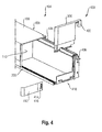
- Fig. 4 shows that the container 104 is associated with a fuse element 400.
- the securing element 400 is designed as a side wall 300 and further comprises a stop 402 integrally formed on the side wall 300 in the present exemplary embodiment.
- the stop 402 is formed so that it engages in a guide 404 of the base body 200 and thus closes an end 406 of the guide 404, in which a door portion 408 of the door 106, 108 engages.
- the stop 402 is formed in the present embodiment on the side wall 300. That is, the side wall 300 and the stopper 402 are in the present embodiment, for example made of plastic material by injection molding.
- the stopper 402 closes the end 406 of the guide 404, so that the door 106, 108 can not be displaced by displacement along the extension direction of the guide 404, until the door portion 408 and the guide 404 disengage.
- the securing element 400 is connected in the present embodiment by a latching connection 410 with the base body 200.
- the latching connection 410 comprises a latching part 412.
- the latching part 412 in the present exemplary embodiment has an engagement section 416, which in the present exemplary embodiment can be displaced manually by a weakening section 414.
- the detent member 412 secures the securing member 400 to the body 200.
- the engaging portion 416 is manually displaced by a user to disengage it from the body 200, the detent member 412 can be removed. Subsequently, the fuse element 400 can be removed from the main body 200 by a user so that the stopper 402 no longer seals the end 406 of the guide 404.
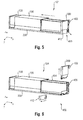
- a first step (see Fig. 5 ) of disassembly, the container 108 is removed from the interior 102 of the refrigeration device 100 by being separated from the inside 116 of the lower refrigerator door 112.
- the side rails 202 of the lower refrigerator door 112 are no longer in contact with the container 108, in particular its side walls 300.
- the side rails 202 no longer block a displacement of the side walls 300 .
- the container 108 is opened by displacing the first door 106 in the container width direction X.
- a second step first the engaging portion 416 is manually displaced by a user, so that the locking part 412 can be removed by a displacement in the arrow direction.
- the locking part 412 is displaced in container depth direction Y.
- the securing element 400 can be removed by a displacement in the second direction of the arrow.
- the securing element 400 is displaced in container high direction Z.
- the first door 106 in the present embodiment is displaced in the direction of the arrow until the door section 408 and the guide 404 are disengaged and thus the first door 106 is separated from the main body 200.
- the displacement takes place in the container width direction X.
- a fourth step (see Fig. 8 ), the second door 108 in the present embodiment is then displaced in the direction of the arrow until the door section 408 and the guide 404 are disengaged and thus the second door 108 is also separated from the main body 200. In the present embodiment, this displacement also takes place in the container width direction X. Subsequently, in the present exemplary embodiment, the separating wall 110 detachably fastened to the base body 200 can be removed.
- the procedure is reversed.
- the partition 110 is reinstalled.
- the second door 108 and then the first door 106 is mounted again, wherein the door portion 408 are again brought by a displacement in the container width direction X in engagement with the guide 404.
- the securing element 400 is again mounted by a displacement in the container vertical direction Z, and then the container by the assembly of the locking part 412 completed, which is this again shifts in container depth direction Y.
- the complete container 108 can be used in the interior 102 of the refrigerator 100 again.
Landscapes
- Engineering & Computer Science (AREA)
- Chemical & Material Sciences (AREA)
- Combustion & Propulsion (AREA)
- Physics & Mathematics (AREA)
- Mechanical Engineering (AREA)
- Thermal Sciences (AREA)
- General Engineering & Computer Science (AREA)
- Refrigerator Housings (AREA)
Applications Claiming Priority (1)
| Application Number | Priority Date | Filing Date | Title |
|---|---|---|---|
| DE102012221799.1A DE102012221799A1 (de) | 2012-11-28 | 2012-11-28 | Kältegerät mit einem Behälter |
Publications (2)
| Publication Number | Publication Date |
|---|---|
| EP2738499A2 true EP2738499A2 (fr) | 2014-06-04 |
| EP2738499A3 EP2738499A3 (fr) | 2017-10-04 |
Family
ID=49641488
Family Applications (1)
| Application Number | Title | Priority Date | Filing Date |
|---|---|---|---|
| EP13192516.6A Withdrawn EP2738499A3 (fr) | 2012-11-28 | 2013-11-12 | Appareil frigorifique doté d'un récipient |
Country Status (2)
| Country | Link |
|---|---|
| EP (1) | EP2738499A3 (fr) |
| DE (1) | DE102012221799A1 (fr) |
Citations (2)
| Publication number | Priority date | Publication date | Assignee | Title |
|---|---|---|---|---|
| US2072300A (en) * | 1935-11-25 | 1937-03-02 | Puffer Hubbard Mfg Co | Sliding door seal for refrigerating apparatus |
| DE102010002415A1 (de) | 2010-02-26 | 2011-09-01 | BSH Bosch und Siemens Hausgeräte GmbH | Kältegerät aufweisend ein Lagerabteil mit Schiebetür |
Family Cites Families (10)
| Publication number | Priority date | Publication date | Assignee | Title |
|---|---|---|---|---|
| US363077A (en) * | 1887-05-17 | Folding crate | ||
| US4561554A (en) * | 1981-09-25 | 1985-12-31 | Swincicki Edmund J | Container for produce, fruits groceries and the like |
| EP0233348A1 (fr) * | 1986-02-05 | 1987-08-26 | Gebrüder Vieler GmbH | Vitrine, en particulier vitrine réfrigérante |
| DE19830325A1 (de) * | 1998-07-07 | 2000-01-13 | Bsh Bosch Siemens Hausgeraete | Abstellfach |
| US7229143B2 (en) * | 2003-09-25 | 2007-06-12 | Maytag Corporation | Refrigerator shelf retainer assembly |
| CN101025325B (zh) * | 2006-02-21 | 2010-10-06 | 海尔集团公司 | 可伸缩式冰箱冷藏瓶座 |
| KR100829131B1 (ko) * | 2006-12-26 | 2008-05-13 | 위니아만도 주식회사 | 저장용기 |
| DE102010003839A1 (de) * | 2010-04-09 | 2011-10-13 | BSH Bosch und Siemens Hausgeräte GmbH | Türabsteller für ein Kältegerät |
| DE102011006235A1 (de) * | 2011-03-28 | 2012-10-04 | BSH Bosch und Siemens Hausgeräte GmbH | Kühlgutablage und Kältegerät |
| KR20120007633U (ko) * | 2011-04-27 | 2012-11-06 | 윤성욱 | 조립식 수납상자 |
-
2012
- 2012-11-28 DE DE102012221799.1A patent/DE102012221799A1/de not_active Withdrawn
-
2013
- 2013-11-12 EP EP13192516.6A patent/EP2738499A3/fr not_active Withdrawn
Patent Citations (2)
| Publication number | Priority date | Publication date | Assignee | Title |
|---|---|---|---|---|
| US2072300A (en) * | 1935-11-25 | 1937-03-02 | Puffer Hubbard Mfg Co | Sliding door seal for refrigerating apparatus |
| DE102010002415A1 (de) | 2010-02-26 | 2011-09-01 | BSH Bosch und Siemens Hausgeräte GmbH | Kältegerät aufweisend ein Lagerabteil mit Schiebetür |
Also Published As
| Publication number | Publication date |
|---|---|
| EP2738499A3 (fr) | 2017-10-04 |
| DE102012221799A1 (de) | 2014-05-28 |
Similar Documents
| Publication | Publication Date | Title |
|---|---|---|
| EP2932173B1 (fr) | Appareil frigorifique muni d'un balconnet de porte | |
| EP2880387B1 (fr) | Appareil frigorifique muni d'une tablette | |
| EP2951515A1 (fr) | Appareil de réfrigération muni d'un bac | |
| DE102009046612A1 (de) | Kältegerät mit einem Türabsteller und einer schwimmend gelagerten Rastvorrichtung | |
| DE102012223110A1 (de) | Haushaltskältegerät mit einem höhenverstellbaren Türabsteller | |
| EP2965028B1 (fr) | Appareil de froid équipé d'un contenant pouvant être déplacé | |
| EP2859287B1 (fr) | Réfrigérateur doté d'un rail de support | |
| EP2738499A2 (fr) | Appareil frigorifique doté d'un récipient | |
| EP2743621B1 (fr) | Appareil frigorifique avec tablette | |
| EP2875293B1 (fr) | Procédé d'assemblage d'un appareil frigorifique, et appareil frigorifique | |
| EP2898272B1 (fr) | Appareil réfrigérant muni d'un bac | |
| EP2618084B1 (fr) | Dispositif de dépôt avec un dispositif de fixation de clapet et appareil ménager réfrigérant avec un tel dispositif de dépôt | |
| EP3019800B1 (fr) | Appareil frigorifique pourvu d'un canal d'air | |
| WO2014135389A1 (fr) | Appareil de froid pourvu d'un tiroir pouvant être déplacé | |
| DE102012221800A1 (de) | Kältegerät mit einem Kunststoffbehälter | |
| EP2743620A2 (fr) | Appareil frigorifique avec tablette | |
| DE102011006798A1 (de) | Haushaltskältegerät mit einer Kühlgut-Aufnahmeeinrichtung sowie Verfahren zur Herstellung einer Kühlgut-Aufnahmeeinrichtung | |
| WO2014090696A1 (fr) | Appareil de froid comportant un balconnet de rangement | |
| DE102012212400A1 (de) | Kältegerät mit einem Behälter | |
| DE102012211770B4 (de) | Kältegerät mit einer Wasserausgabe | |
| DE102010027922A1 (de) | Türblatt und Kältegerät mit einem Türblatt | |
| DE102015014696A1 (de) | Kühlschrank mit innenliegendem Gefrierteil | |
| DE102012216906A1 (de) | Kältegerät mit einem Behälter | |
| DE102012223630A1 (de) | Kältegerät mit einer Eiswürfelbehälter-Einführhilfseinrichtung |
Legal Events
| Date | Code | Title | Description |
|---|---|---|---|
| PUAI | Public reference made under article 153(3) epc to a published international application that has entered the european phase |
Free format text: ORIGINAL CODE: 0009012 |
|
| 17P | Request for examination filed |
Effective date: 20131112 |
|
| AK | Designated contracting states |
Kind code of ref document: A2 Designated state(s): AL AT BE BG CH CY CZ DE DK EE ES FI FR GB GR HR HU IE IS IT LI LT LU LV MC MK MT NL NO PL PT RO RS SE SI SK SM TR |
|
| AX | Request for extension of the european patent |
Extension state: BA ME |
|
| RAP1 | Party data changed (applicant data changed or rights of an application transferred) |
Owner name: BSH HAUSGERAETE GMBH |
|
| PUAL | Search report despatched |
Free format text: ORIGINAL CODE: 0009013 |
|
| AK | Designated contracting states |
Kind code of ref document: A3 Designated state(s): AL AT BE BG CH CY CZ DE DK EE ES FI FR GB GR HR HU IE IS IT LI LT LU LV MC MK MT NL NO PL PT RO RS SE SI SK SM TR |
|
| AX | Request for extension of the european patent |
Extension state: BA ME |
|
| RIC1 | Information provided on ipc code assigned before grant |
Ipc: F25D 23/04 20060101AFI20170831BHEP |
|
| STAA | Information on the status of an ep patent application or granted ep patent |
Free format text: STATUS: REQUEST FOR EXAMINATION WAS MADE |
|
| R17P | Request for examination filed (corrected) |
Effective date: 20180404 |
|
| RBV | Designated contracting states (corrected) |
Designated state(s): AL AT BE BG CH CY CZ DE DK EE ES FI FR GB GR HR HU IE IS IT LI LT LU LV MC MK MT NL NO PL PT RO RS SE SI SK SM TR |
|
| STAA | Information on the status of an ep patent application or granted ep patent |
Free format text: STATUS: EXAMINATION IS IN PROGRESS |
|
| 17Q | First examination report despatched |
Effective date: 20191023 |
|
| GRAP | Despatch of communication of intention to grant a patent |
Free format text: ORIGINAL CODE: EPIDOSNIGR1 |
|
| STAA | Information on the status of an ep patent application or granted ep patent |
Free format text: STATUS: GRANT OF PATENT IS INTENDED |
|
| INTG | Intention to grant announced |
Effective date: 20200930 |
|
| STAA | Information on the status of an ep patent application or granted ep patent |
Free format text: STATUS: THE APPLICATION IS DEEMED TO BE WITHDRAWN |
|
| 18D | Application deemed to be withdrawn |
Effective date: 20210211 |