EP2738510A2 - Échangeur thermique à courant croisé présentant une densité d'ailettes graduée - Google Patents
Échangeur thermique à courant croisé présentant une densité d'ailettes graduée Download PDFInfo
- Publication number
- EP2738510A2 EP2738510A2 EP20130185808 EP13185808A EP2738510A2 EP 2738510 A2 EP2738510 A2 EP 2738510A2 EP 20130185808 EP20130185808 EP 20130185808 EP 13185808 A EP13185808 A EP 13185808A EP 2738510 A2 EP2738510 A2 EP 2738510A2
- Authority
- EP
- European Patent Office
- Prior art keywords
- passages
- row
- fluid
- fins
- air
- Prior art date
- Legal status (The legal status is an assumption and is not a legal conclusion. Google has not performed a legal analysis and makes no representation as to the accuracy of the status listed.)
- Withdrawn
Links
- 239000012530 fluid Substances 0.000 claims description 131
- 238000004891 communication Methods 0.000 claims description 20
- 230000007613 environmental effect Effects 0.000 claims description 13
- 238000000034 method Methods 0.000 claims description 9
- 230000002708 enhancing effect Effects 0.000 claims description 4
- 230000001965 increasing effect Effects 0.000 abstract description 16
- 238000001816 cooling Methods 0.000 abstract description 13
- 230000009286 beneficial effect Effects 0.000 abstract description 4
- 238000010438 heat treatment Methods 0.000 abstract description 4
- 239000002184 metal Substances 0.000 description 30
- 229910052751 metal Inorganic materials 0.000 description 26
- 229910001092 metal group alloy Inorganic materials 0.000 description 15
- 238000010276 construction Methods 0.000 description 10
- 238000005219 brazing Methods 0.000 description 9
- 239000007789 gas Substances 0.000 description 9
- 239000000463 material Substances 0.000 description 7
- 238000010586 diagram Methods 0.000 description 6
- 238000005260 corrosion Methods 0.000 description 4
- 230000007797 corrosion Effects 0.000 description 4
- 230000001143 conditioned effect Effects 0.000 description 3
- 230000007423 decrease Effects 0.000 description 3
- 230000001105 regulatory effect Effects 0.000 description 3
- IJGRMHOSHXDMSA-UHFFFAOYSA-N Atomic nitrogen Chemical compound N#N IJGRMHOSHXDMSA-UHFFFAOYSA-N 0.000 description 2
- 238000004378 air conditioning Methods 0.000 description 2
- 230000001276 controlling effect Effects 0.000 description 2
- XLYOFNOQVPJJNP-UHFFFAOYSA-N water Substances O XLYOFNOQVPJJNP-UHFFFAOYSA-N 0.000 description 2
- RTAQQCXQSZGOHL-UHFFFAOYSA-N Titanium Chemical compound [Ti] RTAQQCXQSZGOHL-UHFFFAOYSA-N 0.000 description 1
- 230000002159 abnormal effect Effects 0.000 description 1
- 229910052782 aluminium Inorganic materials 0.000 description 1
- XAGFODPZIPBFFR-UHFFFAOYSA-N aluminium Chemical compound [Al] XAGFODPZIPBFFR-UHFFFAOYSA-N 0.000 description 1
- 230000006835 compression Effects 0.000 description 1
- 238000007906 compression Methods 0.000 description 1
- 230000000694 effects Effects 0.000 description 1
- 239000000284 extract Substances 0.000 description 1
- 239000000446 fuel Substances 0.000 description 1
- 229910001026 inconel Inorganic materials 0.000 description 1
- 229910052757 nitrogen Inorganic materials 0.000 description 1
- 239000010936 titanium Substances 0.000 description 1
- 229910052719 titanium Inorganic materials 0.000 description 1
- 238000011144 upstream manufacturing Methods 0.000 description 1
Images



Classifications
-
- F—MECHANICAL ENGINEERING; LIGHTING; HEATING; WEAPONS; BLASTING
- F28—HEAT EXCHANGE IN GENERAL
- F28F—DETAILS OF HEAT-EXCHANGE AND HEAT-TRANSFER APPARATUS, OF GENERAL APPLICATION
- F28F3/00—Plate-like or laminated elements; Assemblies of plate-like or laminated elements
- F28F3/02—Elements or assemblies thereof with means for increasing heat-transfer area, e.g. with fins, with recesses, with corrugations
- F28F3/025—Elements or assemblies thereof with means for increasing heat-transfer area, e.g. with fins, with recesses, with corrugations the means being corrugated, plate-like elements
-
- F—MECHANICAL ENGINEERING; LIGHTING; HEATING; WEAPONS; BLASTING
- F28—HEAT EXCHANGE IN GENERAL
- F28D—HEAT-EXCHANGE APPARATUS, NOT PROVIDED FOR IN ANOTHER SUBCLASS, IN WHICH THE HEAT-EXCHANGE MEDIA DO NOT COME INTO DIRECT CONTACT
- F28D9/00—Heat-exchange apparatus having stationary plate-like or laminated conduit assemblies for both heat-exchange media, the media being in contact with different sides of a conduit wall
- F28D9/0062—Heat-exchange apparatus having stationary plate-like or laminated conduit assemblies for both heat-exchange media, the media being in contact with different sides of a conduit wall the conduits for one heat-exchange medium being formed by spaced plates with inserted elements
-
- F—MECHANICAL ENGINEERING; LIGHTING; HEATING; WEAPONS; BLASTING
- F28—HEAT EXCHANGE IN GENERAL
- F28D—HEAT-EXCHANGE APPARATUS, NOT PROVIDED FOR IN ANOTHER SUBCLASS, IN WHICH THE HEAT-EXCHANGE MEDIA DO NOT COME INTO DIRECT CONTACT
- F28D21/00—Heat-exchange apparatus not covered by any of the groups F28D1/00 - F28D20/00
- F28D2021/0019—Other heat exchangers for particular applications; Heat exchange systems not otherwise provided for
- F28D2021/0021—Other heat exchangers for particular applications; Heat exchange systems not otherwise provided for for aircrafts or cosmonautics
-
- F—MECHANICAL ENGINEERING; LIGHTING; HEATING; WEAPONS; BLASTING
- F28—HEAT EXCHANGE IN GENERAL
- F28F—DETAILS OF HEAT-EXCHANGE AND HEAT-TRANSFER APPARATUS, OF GENERAL APPLICATION
- F28F2215/00—Fins
- F28F2215/04—Assemblies of fins having different features, e.g. with different fin densities
Definitions
- This disclosure generally relates to heat exchangers and, more specifically, relates to cross-flow heat exchangers used in conjunction with aircraft environmental control systems.
- pressurized aircraft have an environmental control system (ECS) for maintaining cabin pressurization and controlling cabin temperatures during flight.
- ECS environmental control system
- outside air is supplied to the cabin via air conditioning packs and a portion of the air in the cabin is recirculated by recirculation fans to provide an acceptable level of volumetric airflow to the aircraft passengers.
- bleed air pressurized air
- bleed ports located at various stages of compression in a multi-stage compressor section of the engine.
- a high-pressure bleed port is used to supply sufficient bleed air over the operating range of the aircraft. The temperature of this bleed air is normally too high for the ECS and some precooling of the bleed air is required.
- precooler a cross-flow, air-to-air heat exchanger, called a precooler, for cooling hot air bled from a compressor of a gas turbine engine. That cooled air is then supplied to the aircraft ECS.
- the hot bleed air is cooled in the precooler by cold air diverted from and then returned to the fan duct.
- Precooled air for the ECS travels through air conditioning packs to provide essentially dry, sterile, and dust-free conditioned air to the airplane cabin. This conditioned air is then mixed with a predetermined amount of cabin recirculated air and delivered to the aircraft cabin. Trim air, taken downstream of the precooler, may be added to warm the conditioned air to a suitably comfortable level for the aircraft cabin.
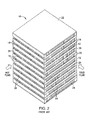
- FIG. 2 illustrates a typical precooler construction.
- This typical precooler 10 is a cross-flow air-to-air heat exchanger comprising a stack of N rows of air passages, where N is an odd integer equal to 3 or more. If the stacked rows of passages were to be numbered from 1 to N , starting at the bottom of the precooler, then it can be seen in FIG. 2 that the odd-numbered rows are aligned in a first direction indicated by the arrow labeled "COLD FLUID", while the even-numbered rows are aligned in a second direction indicated by the arrow labeled "HOT FLUID". (Alternatively, there are some precooler constructions with odd-numbered rows on the hot fluid side and even-numbered rows on the cold fluid side.) In the construction shown in FIG. 2 , the second direction is perpendicular to the first direction.
- Each air passage seen in FIG. 2 has openings at both ends and a constant cross-sectional area along its length.
- the openings of the odd-numbered rows of passages 12 located on one side of precooler 10 which is visible in FIG. 2 are in fluid communication with a source of cold air
- the openings of the even-numbered rows of passages 14 located on the other side of precooler 10 which is visible in FIG. 2 are in fluid communication with a source of hot air.
- passages 12 will be referred to as “cold passages” and passages 14 will be referred to as “hot passages” to reflect the difference in temperatures of the air flowing through those passages.
- the passages within any row have the same height.
- the height of cold passages 12 may be different than the height of hot passages 14.
- the rows of cold and hot passages are arranged so that each row of hot passages 14 is sandwiched between a row of cold passages 12 disposed directly above and a row of cold passages 12 disposed directly below. (Alternatively, each row of cold passages could be sandwiched between respective hot passages above and below.)
- Adjacent rows of hot and cold passages are thermal-conductively coupled to each other by means of respective rectangular planar parting plates disposed inside precooler 10 in mutually parallel relationship.
- a precooler with N rows of stacked hot and cold passages has ( N - 1) parting plates.
- the parting plates are rigidly supported in a mutually parallel relationship by a frame that comprises a multiplicity of pairs of mutually parallel cold passages closure bar 18 (a respective pair of cold passages closure bar flanking each row of cold passages), a multiplicity of pairs of mutually parallel hot passages closure bar 20 (a respective pair of hot passages closure bar flanking each row of hot passages) oriented perpendicular to the cold passages closure bar and having ends interleaved between the ends of cold passages closure bar 18, and a pair of side plates 22 and 24 which are respectively affixed to the outermost (first and last) pairs of cold passages closure bar 18.
- the side plates could be affixed to outermost pairs of hot passages closure bars.
- the side plates 22, 24 are disposed parallel to the parting plates and adjacent to the first and N -th rows of air passages, which in the depicted construction are cold passages.
- precooler 10 During operation of precooler 10 shown in FIG. 2 , cold air flows through cold passages 12 and hot air flows through hot passages 14, which results in the transfer of heat from the hot air to the cold air by thermal conduction.
- the heat exchanger thus extracts heat from the hot air to lower its temperature to the degree required by the particular application.
- each row of air passages using a multiplicity of mutually parallel fins which extend between a respective pair of adjacent parting plates.
- fins 26 partly define cold passages 12, while fins 28 partly define hot passages 14.
- fins 26 are spaced at equal intervals within each row of cold passages 12 (i.e., the rows of cold passages have a constant fin density), while fins 28 are spaced at equal intervals within each row of hot passages 14 (i.e., the rows of hot passages have a constant fin density).
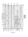
- FIG. 3 shows the hot air front side of a precooler having constant fin density, i.e., the view in FIG. 3 is taken on the side where hot air enters the hot passages.
- Each row of hot passages 14 comprises a corrugated sheet 30 made of metal or metal alloy which is placed between a pair of parting plates 16. The corrugated metal sheet 30 is formed by folding.
- Each corrugated metal sheet 30 is made of a corrosion-resistant metal or metallic alloy having a high thermal conductivity.
- each corrugated metal sheet 30 has three types of corrugated sheet segments: passage top segments 32, passage bottom segment 34, and fins 28 which connect passage ceiling segments 32 to passage floor segments 34.
- passage top segments 32 As seen in FIG. 3 , each corrugated metal sheet 30 has three types of corrugated sheet segments: passage top segments 32, passage bottom segment 34, and fins 28 which connect passage ceiling segments 32 to passage floor segments 34.
- fins 28 which connect passage ceiling segments 32 to passage floor segments 34.
- the first hot passage 14a is formed by fins 28a, 28b, a passage top segment 30a connecting fins 28a, 28b, and a portion of a lower parting plate 16a that opposes passage top segment 30a across hot passage 14a
- the second hot passage 14b is formed by fins 28b, 28c, a passage bottom segment 34a connecting fins 28b, 28c, and a portion of the upper parting plate 16b that opposes passage bottom segment 34a across hot passage 14b.
- all of the passage top segments 32 in each row of hot passages are brazed to the bottom surface of a respective parting plate disposed above the row, while all of the passage bottom segments 34 in each row of hot passages are brazed to the top surface of a respective parting plate disposed below the row.
- the preferred brazing material has high thermal conductivity, thereby facilitating the transfer of heat at the interface between a parting plate and a passage top or bottom segment.
- a heat exchanger is depicted in which the fin density across each row of hot passages is constant. Likewise the fin density across each row of cold passages is constant.
- the subject matter disclosed herein is a cross-flow air-to-air heat exchanger in which rows of hot passages are interleaved with rows of cold passages, adjacent rows of hot and cold passages being separated by respective parting plates made of a corrosion-resistant metal or metallic alloy having a high thermal conductivity (e.g., Inconel).
- the parting plates are parallel to each other.
- the parting plates act as heat sinks which facilitate the transfer of heat from hot passages to cold passages, thereby cooling the hot air that flows through the heat exchanger.
- the heat exchanger has four sides and rectangular planar parting plates having the same shape and dimensions. All of the hot passages can be oriented parallel to a first axis while all of the cold passages can be oriented parallel to a second axis which is not parallel to (and can be perpendicular to) the first axis.
- the cold air enters the cold passages on a first side of the heat exchanger and exits the cold passages on a second side of the heat exchanger opposite to the first side; similarly, the hot air enters the hot passages on a third side of the heat exchanger and exits the hot passages on a fourth side of the heat exchanger opposite to the third side.
- Each row of passages may be formed in part by a respective multiplicity of fins.
- the fins of any row of passages are parallel to each other.
- the fins may be oriented perpendicular to the adjacent parting plates, thereby forming passages which have rectangular cross sections.
- the fins of each row of passages could be oriented to form passages having trapezoidal cross sections.
- Such a row comprises a first set of mutually parallel fins interleaved with a second set of mutually parallel fins, the fins of the second set being not parallel with the fins of the first set.
- the fins may be formed by folding a metal sheet to form corrugations.
- Each corrugated metal sheet is installed between a respective pair of adjacent parting plates.
- Each corrugated metal sheet is made of a corrosion-resistant metal or metallic alloy having a high thermal conductivity.
- the corrugated metal sheet comprises alternating ridges and grooves.
- the same corrugated metal sheet can be described in terms of three types of corrugated sheet segments: a passage top segment, a passage bottom segment, and a passage wall connecting a passage top segment to a passage bottom segment.
- passage walls will be referred to as "fins", and the passage top and bottom segments will not be so designated, i.e., for the purpose of this disclosure, the term “fins” in the appended claims should not be construed to encompass passage top segments or passage bottom segments of a corrugated metal sheet.
- the first air passage can be formed by first and second fins, a first passage top segment connecting the first and second fins, and a portion of the lower parting plate disposed between the first and second fins and opposite to the first passage top segment
- the second air passage can be formed by the second fin and a third fin, a first passage bottom segment connecting the second and third fins, and a portion of the upper parting plate disposed between the second and third fins and opposite to the first passage bottom segment.
- all of the passage top segments are brazed to the upper parting plate, while all of the passage bottom segments are brazed to the lower parting plate.
- the preferred brazing material has high thermal conductivity, thereby facilitating the transfer of heat at the interface between a parting plate and a passage top or bottom segment.
- each row of passages could be formed by brazing a set of mutually parallel fins to the adjacent parting plates.
- brazing material could be placed on both sides of each fin at the latter's top and bottom to form fillets made of brazing material.
- fin density means a number of fins per unit length (e.g., inch). It is known to provide a cross-flow heat exchanger in which each row of hot and cold passages has a uniform (i.e., constant) fin density in a direction normal to the fins that form those passages.
- the heat transfer capacity of a cross-flow heat exchanger can be increased by changing or graduating the density of the fins, which partly define a row of adjacent hot passages, in a direction normal to those fins.
- the fin density in each row of hot passages is lower in a first region near the cold air inlets than it is in a second region located between the first region and the cold air outlets. This has the beneficial effect of increasing the rate of flow of hot air through hot passages adjacent or near to the cold air inlets of the heat exchanger, i.e., where the temperature of the cold air is coldest. As cold air flows along each cold passage, the cold air is heating up, becoming less capable of cooling the hot air in the adjacent hot passages as it gets closer to the cold air outlets.
- this concept can also be applied to the cold passages, i.e., by changing or graduating the density of the fins that form a row of cold passages in the direction normal to those fins.
- One aspect of the disclosed subject matter is a system comprising a source of relatively colder fluid, a source of relatively hotter fluid, and a cross-flow fluid-to-fluid heat exchanger connected to receive fluid from the sources of relatively colder and hotter air, wherein the heat exchanger comprises: a first multiplicity of fins which partly define a first row of passages having respective fluid inlets connected to receive fluid from the source of relatively hotter fluid and respective fluid outlets in fluid communication with the respective fluid inlets of the first row of passages; a second multiplicity of fins which partly define a second row of passages having respective fluid inlets connected to receive fluid from the source of relatively colder fluid and respective fluid outlets in fluid communication with the respective fluid inlets of the second row of passages; and a plate disposed between the first and second multiplicities of fins, wherein at least one of the first and second multiplicities of fins has a non-uniform fin density.
- the non-uniform fin density comprises a first fin density in a first region and a second fin density in a second region of at least one of the first and second rows of passages, the first fin density being less than the second fin density.
- the first region is closer than the second region to the fluid inlets of the at least one of the first and second rows of passages.
- the non-uniform fin density decreases in graduations from the fluid inlets to the fluid outlets of the at least one of the first and second rows of passages.
- the fluid is air in the disclosed embodiments
- the concept of increasing the fin density with increasing distance from the air inlets of the passages has application in cross-flow heat exchangers which use other types of fluid, such as water or oil.
- the sources of relatively colder and relatively hotter fluids are respectively a fan duct and a compressor of a gas turbine engine.
- An environmental control system can be connected to receive cooled air from the heat exchanger.
- Another aspect is a system comprising a source of relatively colder air, a source of relatively hotter air, and a cross-flow air-to-air heat exchanger connected to receive air from the sources of relatively colder and hotter air
- the heat exchanger comprises: a first multiplicity of fins which partly define a first row of passages having respective air inlets connected to receive air from the source of relatively hotter air and respective air outlets in fluid communication with the respective air inlets of the first row of passages; a second multiplicity of fins which partly define a second row of passages having respective air inlets connected to receive air from the source of relatively colder air and respective air outlets in fluid communication with the respective air inlets of the second row of passages; and a plate disposed between the first and second multiplicities of fins, wherein the first multiplicity of fins has a first fin density in a first region and a second fin density greater than the first fin density in a second region, and the first region is closer than the second region to the air inlets of the first row of passages.
- a further aspect of the subject matter disclosed herein is a cross-flow heat exchanger comprising: a first multiplicity of fins which partly define a first row of passages extending in a first direction, each passage of the first row having respective openings at opposite ends thereof; a second multiplicity of fins which partly define a second row of passages extending in a second direction that is not parallel to the first direction, each passage of the second row having respective openings at opposite ends thereof; and a plate disposed between the first and second multiplicities of fins, wherein the first multiplicity of fins comprise first, second and third fins, the first and second fins partly defining a first passage of the first row of passages having a first constant cross-sectional area along its length, and the second and third fins partly defining a second passage of the first row of passages having a second constant cross-sectional area along its length, the first constant cross-sectional area being greater than the second constant cross-sectional area.
- the first multiplicity of fins may comprise respective portions of a continuous corrugated sheet made of metal or metal alloy.
- a cross-flow heat exchanger comprising: a first multiplicity of fins which partly define a first row of passages extending in a first direction, each passage of the first row having respective openings at opposite ends thereof; a second multiplicity of fins which partly define a second row of passages extending in a second direction that is not parallel to the first direction, each passage of the second row having respective openings at opposite ends thereof; a third multiplicity of fins which partly define a third row of passages extending in the first direction, each passage of the third row having respective openings at opposite ends thereof; a first plate disposed between the first and second multiplicities of fins; and a second plate disposed between the second and third multiplicities of fins, wherein the second row of passages is sandwiched between the first and third rows of passages, thermal conductively coupled to the first row of passages via at least the first plate, and thermal conductively coupled to the third row of passages via at least the second plate, and wherein the second multiplicity of fins has
- Another aspect is a method for enhancing performance of a cross-flow heat exchanger, comprising the following steps performed concurrently: passing cold fluid through a first row of passages of the heat exchanger, the passages of the first row being separated by fins; passing hot fluid through first and second sets of passages of a second row of passages of the heat exchanger, the second row of passages being thermal conductively coupled to the first row of passages such that hot fluid flowing through the second row of passages is cooled by cold fluid in the first row of passages, the passages of the second row being separated by fins, wherein the first set of passages of the second row have a first fin density and the second set of passages of the second row have a second fin density less than the first fin density.
- the first set of passages of the second row are disposed within a distance of a fluid inlet side of the first row of passages and the second set of passages of the second row are disposed further away than that distance from the fluid inlet side of the first row of passages.
- the invention can involve a system may include a source of relatively colder fluid, a source of relatively hotter fluid, and a cross-flow fluid-to-fluid heat exchanger connected to receive fluid from the sources of relatively colder and hotter air, wherein the heat exchanger comprises a first multiplicity of fins which partly define a first row of passages having respective fluid inlets connected to receive fluid from the source of relatively hotter fluid and respective fluid outlets in fluid communication with the respective fluid inlets of the first row of passages a second multiplicity of fins which partly define a second row of passages having respective fluid inlets connected to receive fluid from the source of relatively colder fluid and respective fluid outlets in fluid communication with the respective fluid inlets of the second row of passages; and a first plate disposed between the first and second multiplicities of fins, wherein at least one of the first and second multiplicities of fins has a non-uniform fin density.
- the non-uniform fin density may include a first fin density in a first region and a second fin density in a second region, the first fin density being less than the second fin density.
- the first multiplicity of fins may have the first and second fin densities in the first and second regions, the first region being closer than the second region to the fluid inlets of the second row of passages.
- the second multiplicity of fins may have the first and second fin densities in the first and second regions, the first region being closer than the second region to the fluid inlets of the first row of passages.
- the fluid may be air.
- the source of relatively colder fluid may be a fan duct of a gas turbine engine.
- the source of relatively hotter fluid may be a compressor of a gas turbine engine.
- the system may include an environmental control system connected to receive fluid from the fluid outlets of the first row of passages.
- the invention can involve a method for enhancing performance of a cross-flow heat exchanger that may include the following steps performed concurrently: passing cold fluid through a first row of passages of the heat exchanger, the passages of the first row being separated by fins; passing hot fluid through first and second sets of passages of a second row of passages of the heat exchanger, the second row of passages being thermal conductively coupled to the first row of passages such that hot fluid flowing through the second row of passages is cooled by cold fluid in the first row of passages, the passages of the second row being separated by fins, wherein the first set of passages of the second row have a first fin density and the second set of passages of the second row have a second fin density less than the first fin density.
- the first set of passages of the second row may be disposed within a distance of a fluid inlet side of the first row of passages and the second set of passages of the second row are disposed further away than the distance from the fluid inlet side of the first row of passages.
- the invention can involve a system may include a source of relatively colder air, a source of relatively hotter air, and a cross-flow air-to-air heat exchanger connected to receive air from the sources of relatively colder and hotter air, wherein the heat exchanger comprises: a first multiplicity of fins which partly define a first row of passages having respective air inlets connected to receive air from the source of relatively hotter air and respective air outlets in fluid communication with the respective air inlets of the first row of passages; a second multiplicity of fins which partly define a second row of passages having respective air inlets connected to receive air from the source of relatively colder air and respective air outlets in fluid communication with the respective air inlets of the second row of passages; and a first plate disposed between the first and second multiplicities of fins, wherein the first multiplicity of fins has a first fin density in a first region and a second fin density greater than the first fin density in a second region, and the first region is closer than the second region to the air inlets of the first row of
- the source of relatively colder air may be a fan duct of a gas turbine engine.
- the source of relatively hotter air may be a compressor of a gas turbine engine.
- the system may include an environmental control system connected to receive air from the respective air outlets of the one of the first and second rows of passages having air inlets connected to receive air from the source of relatively hotter air.
- the system may also include a third multiplicity of fins which partly define a third row of passages having respective air inlets connected to receive air from the source of relatively hotter air and respective air outlets in fluid communication with the respective air inlets of the third row of passages, the second multiplicity of fins being disposed between the first and third multiplicities of fins; and a second plate disposed between the second and third multiplicities of fins, wherein the third multiplicity of fins has first and second fin densities in first and second regions, the first region being closer than the second region to the air inlets of the third row of passages.
- the invention can include a cross-flow heat exchanger that may include a first multiplicity of fins which partly define a first row of passages extending in a first direction, each passage of the first row having respective openings at opposite ends thereof; a second multiplicity of fins which partly define a second row of passages extending in a second direction that is not parallel to the first direction, each passage of the second row having respective openings at opposite ends thereof; and a first plate disposed between the first and second multiplicities of fins, wherein the first multiplicity of fins may includefirst, second and third fins, the first and second fins partly define a first passage of the first row of passages having a first constant cross-sectional area along its length, and the second and third fins partly define a second passage of the first row of passages having a second constant cross-sectional area along its length, the first constant cross-sectional area being greater than the second constant cross-sectional area.
- the heat exchanger may also include a third multiplicity of fins which partly define a third row of passages extending in the first direction, each passage of the third row having respective openings at opposite ends thereof; and a second plate disposed between second and third multiplicities of fins, wherein the third multiplicity of fins may include fourth, fifth and sixth fins, the fourth and fifth fins partly define a first passage of the third row of passages having the first constant cross-sectional area along its length, and the fifth and sixth fins partly define a second passage of the third row of passages having the second constant cross-sectional area along its length.
- the first multiplicity of fins may include respective portions of a continuous corrugated sheet made of metal or metal alloy.
- the invention can involve a cross-flow heat exchanger that includes a first multiplicity of fins which partly define a first row of passages extending in a first direction, each passage of the first row having respective openings at opposite ends thereof; a second multiplicity of fins which partly define a second row of passages extending in a second direction that is not parallel to the first direction, each passage of the second row having respective openings at opposite ends thereof; and a first plate disposed between the first and second multiplicities of fins, wherein the second row of passages is thermal conductively coupled to the first row of passages via at least the first plate, and the second multiplicity of fins has a non-uniform fin density which varies in a direction normal to the second direction.
- the heat exchanger may also include a third multiplicity of fins which partly define a third row of passages extending in the first direction, each passage of the third row having respective openings at opposite ends thereof; and a second plate disposed between the second and third multiplicities of fins, wherein the second row of passages is thermal conductively coupled to the third row of passages via at least the second plate.
- Each of the first through third multiplicities of fins may include respective portions of a respective continuous corrugated sheet made of metal or metal alloy.
- the method may include delivering cooled air exiting the second row of passages to an environmental control system of an aircraft.
- FIG. 1 shows some components of an aircraft compressor bleed air supply system comprising a heat exchanger 4 for cooling hot compressed air bled from a high-pressure compressor 2 of a gas turbine aircraft engine and then supplying that cooled air to an environmental control system 6.
- the precooler may comprise a cross-flow air-to-air heat exchanger 4 in fluid communication with a source of cooling air, which in the illustrated embodiment is a portion of the rearward air flow produced by the fan 8 of the engine.
- the heat exchanger 4 may be in flow communication with an annular bypass duct (not shown) of the aircraft engine.
- the precooler may also include a variable precooler bypass (not shown) that may be used to bypass the compressor bleed air around the heat exchanger 4.
- precooler heat exchangers are made from lnconel in order to withstand the heat and pressure of the bleed air, but may alternatively be constructed of aluminum or titanium.
- An electronic controller (not shown) is used to control the operation of this compressor bleed air supply system.
- the electronic controller is used to control full or partial opening and closing of various valves (not shown) incorporated in the compressor bleed air supply system.
- the air-to-air heat exchanger 4 may be disposed, for example, inside a core cowl (not shown) surrounding the core engine at a base of struts supporting the nacelle (not shown) and in suitable flow communication with the bypass duct.
- a suitable inlet scoop or door (not shown) in the core cowl operates as a variable fan air valve controlled by the electronic controller.
- the variable fan air valve (not shown) modulates and channels the cooling fan air downstream through the heat exchanger 4.
- the cooling fan air is then conveyed through an outlet channel (not shown), returning the cooling fan air to the bypass duct upstream of a fan outlet at a trailing edge of the nacelle.
- Another option is for outlet fan air to be ducted and dumped overboard.
- the heat exchanger 4 is used to cool the compressor bleed air from the high-pressure compressor 2 with the portion of the fan air diverted from the bypass duct.
- the cooled compressor bleed air then flows to the environmental control system 6 for use therein.
- the compressor bleed air is bled from one of two separate stages (not shown) of the high-pressure compressor 2.
- Bleed shutoff valves may be disposed between the high-pressure compressor 2 and the heat exchanger 4 for opening and closing individual bleed lines under control of the aforementioned electronic controller.
- the pressure of the compressor bleed air may be measured by a pressure sensor incorporated in a regulating shut off valve (not shown) installed in the bleed air inlet line (labeled "BLEED AIR" in FIG.
- a bleed air outlet line (labeled "COOLED AIR" in FIG. 1 ) connects the heat exchanger 4 to the ECS 6.
- a temperature sensor (not shown) can be operably coupled to the bleed air outlet line for measuring a precooler exit temperature of the compressor bleed air before it is conveyed to the ECS 6.
- the temperature sensor is connected to the electronic controller for controlling the fan air modulating valve based at least in part on the temperature measured by the temperature sensor.
- An optional pressure sensor may be operably coupled to the bleed air outlet line for measuring a precooler exit pressure, which may be used to measure pressure differential across the precooler.
- the electronic controller controls and operates the various valves in a manner to maintain the precooler exit temperature in a specified range.
- the function of the compressor bleed air supply system shown in FIG. 1 is to supply compressor bleed air to the ECS 6 and optionally to the aircraft wing anti-icing system and to the nitrogen generation system (not shown).
- the compressor bleed air must be supplied at sufficient flow rates, pressures and temperatures to meet ECS requirements under normal and abnormal operating conditions.
- the heat transfer capacity of a cross-flow heat exchanger having the construction shown in FIG. 3 can be increased by changing or graduating the density of the fins, which partly define a row of adjacent hot passages, in a direction normal to those fins.
- the fin density in each row of hot passages is lower in a first region near the cold air inlets than it is in a second region located between the first region and the cold air outlets. This has the beneficial effect of increasing the rate of flow of hot air through hot passages adjacent or near to the cold air inlets of the heat exchanger, i.e., where the temperature of the cold air is coldest. As cold air flows along each cold passage, the cold air is heating up, becoming less capable of cooling the hot air in the adjacent hot passages as it gets closer to the cold air outlets.
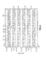
- each row of hot passages has a first region in which the fin density FD 1 is less than the fin density FD 2 in a second region (i.e., FD 1 ⁇ FD 2 ), wherein the first region is disposed between the cold air front side of the precooler and the second region.
- each row of hot passages could have M regions (where M is an integer greater than two), wherein the fin density in the first region is FD 1 is less than the fin density FD 2 in a second region, which in turn is less than the fin density FD 3 in a third region, etc. (i.e., FD 1 ⁇ FD 2 ⁇ FD 3 ⁇ ... ⁇ FD M ), wherein the first through M -th regions are be disposed in sequence from left to right when the precooler is viewed from its hot air front side.
- This principle can be extended to provide a row of hot passages in which the distance separating successive fins decreases incrementally (i.e., the fin density increases incrementally) across the row of hot passages from the cold air front side to the cold air back side of the precooler, i.e., the fin density is graduated.
- fins 26 have a constant fin density across the row of cold passages
- fins 28 have a fin density which increases from FD 1 to FD 2 to FD 3 across the hot passages in a direction from the cold fluid inlets to the cold fluid outlets.
- nonuniform fin density concept can also be applied to the cold passages, i.e., by changing or graduating the density of the fins that form a row of cold passages in the direction normal to those fins.
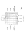
- FIG. 6 is a top view showing a configuration wherein a row of hot passages, separated by parallel fins 26 (indicated by solid lines), are disposed above a row of cold passages, separated by a plurality of fins 26 (indicated by dashed lines) disposed perpendicular to fins 28.
- fins 28 have a constant fin density across the row of hot passages
- fins 26 have a fin density which increases from FD 1 to FD 2 across the cold passages in a direction from the hot fluid inlets to the cold fluid outlets.
- the heat exchanger has four sides and rectangular planar parting plates having the same shape and dimensions. All of the hot passages can be oriented parallel to a first axis while all of the cold passages can be oriented parallel to a second axis which is not parallel to (and can be perpendicular to) the first axis.
- the cold air enters the cold passages on a first side of the heat exchanger and exits the cold passages on a second side of the heat exchanger opposite to the first side; similarly, the hot air enters the hot passages on a third side of the heat exchanger and exits the hot passages on a fourth side of the heat exchanger opposite to the third side.
- Each row of passages may be formed in part by a respective multiplicity of fins.
- the fins of any row of passages are parallel to each other.
- the fins may be oriented perpendicular to the adjacent parting plates, thereby forming passages which have rectangular cross sections.
- the fins of each row of passages could be oriented to form passages having trapezoidal cross sections.
- Such a row comprises a first set of mutually parallel fins interleaved with a second set of mutually parallel fins, the fins of the second set being not parallel with the fins of the first set.
- the fins may be formed by folding a metal sheet to form corrugations.
- Each corrugated metal sheet is installed between a respective pair of adjacent parting plates.
- Each corrugated metal sheet is made of a corrosion-resistant metal or metallic alloy having a high thermal conductivity.
- the corrugated metal sheet comprises alternating ridges and grooves.
- the same corrugated metal sheet can be described in terms of three types of corrugated sheet segments: a passage top segment, a passage bottom segment, and a passage wall connecting a passage top segment to a passage bottom segment.
- the passage walls are "fins", and the passage top and bottom segments will not be so designated, i.e., for the purpose of this disclosure.
- the term “fins” in the appended claims should not be construed to encompass passage top segments or passage bottom segments of a corrugated metal sheet.
- the first air passage can be formed by first and second fins, a first passage top segment connecting the first and second fins, and a portion of the lower parting plate disposed between the first and second fins and opposite to the first passage top segment.
- the second air passage can be formed by the second fin and a third fin, a first passage bottom segment connecting the second and third fins, and a portion of the upper parting plate disposed between the second and third fins and opposite to the first passage bottom segment. Furthermore, this structure is repeated across the row of passages.
- all of the passage top segments are brazed to the upper parting plate, while all of the passage bottom segments are brazed to the lower parting plate.
- the preferred brazing material has high thermal conductivity, thereby facilitating the transfer of heat at the interface between a parting plate and a passage top or bottom segment.
- each row of passages could be formed by brazing a set of mutually parallel fins to the adjacent parting plates.
- brazing material could be placed on both sides of each fin at the latter's top and bottom to form fillets made of brazing material.
- the heat transfer capacity of a cross-flow heat exchanger can be increased by changing or graduating the density of the fins, which partly define a row of adjacent hot passages, in a direction normal to those fins.
- the fin density in each row of hot passages is lower in a first region near the cold air inlets than it is in a second region located between the first region and the cold air outlets. This has the beneficial effect of increasing the rate of flow of hot air through hot passages adjacent or near to the cold air inlets of the heat exchanger, i.e., where the temperature of the cold air is coldest. As cold air flows along each cold passage, the cold air is heating up, becoming less capable of cooling the hot air in the adjacent hot passages as it gets closer to the cold air outlets.
- the heat exchanger includes: a first multiplicity of fins which partly define a first row of passages having respective fluid inlets connected to receive fluid from the source of relatively hotter fluid and respective fluid outlets in fluid communication with the respective fluid inlets of the first row of passages, a second multiplicity of fins which partly define a second row of passages having respective fluid inlets connected to receive fluid from the source of relatively colder fluid and respective fluid outlets in fluid communication with the respective fluid inlets of the second row of passages, and a plate disposed between the first and second multiplicities of fins, wherein at least one of the first and second multiplicities of fins has a non-uniform fin density.
- the non-uniform fin density comprises a first fin density in a first region and a second fin density in a second region of at least one of the first and second rows of passages, the first fin density being less than the second fin density.
- the first region is closer than the second region to the fluid inlets of the at least one of the first and second rows of passages.
- the non-uniform fin density decreases in graduations from the fluid inlets to the fluid outlets of the at least one of the first and second rows of passages.
- the fluid is air in the disclosed embodiments
- the concept of increasing the fin density with increasing distance from the air inlets of the passages has application in cross-flow heat exchangers which use other types of fluid, such as water or oil.
- the sources of relatively colder and relatively hotter fluids are respectively a fan duct and a compressor of a gas turbine engine.
- An environmental control system can be connected to receive cooled air from the heat exchanger.
- Another aspect is a system including a source of relatively colder air, a source of relatively hotter air, and a cross-flow air-to-air heat exchanger connected to receive air from the sources of relatively colder and hotter air, wherein the heat exchanger includes a first multiplicity of fins which partly define a first row of passages having respective air inlets connected to receive air from the source of relatively hotter air and respective air outlets in fluid communication with the respective air inlets of the first row of passages.
- a second multiplicity of fins may be included which partly define a second row of passages having respective air inlets connected to receive air from the source of relatively colder air and respective air outlets in fluid communication with the respective air inlets of the second row of passages.
- a plate may be disposed between the first and second multiplicities of fins.
- the first multiplicity of fins has a first fin density in a first region and a second fin density greater than the first fin density in a second region, and the first region is closer than the second region to the air inlets of the first row of passages.
- a cross-flow heat exchanger that includes a first multiplicity of fins which partly define a first row of passages extending in a first direction.
- each passage of the first row having respective openings at opposite ends thereof and a second multiplicity of fins which partly define a second row of passages extending in a second direction that is not parallel to the first direction.
- each passage of the second row having respective openings at opposite ends thereof, and a plate disposed between the first and second multiplicities of fins.
- the first multiplicity of fins includes first, second and third fins, the first and second fins partly defining a first passage of the first row of passages having a first constant cross-sectional area along its length, and the second and third fins partly defining a second passage of the first row of passages having a second constant cross-sectional area along its length, the first constant cross-sectional area being greater than the second constant cross-sectional area.
- a greater cross-sectional area of the passage corresponds to a reduced fin density (assuming that the fins of the first multiplicity are mutually parallel). More specifically, the first and second fins are separated by a first distance, and the second and third fins are separated by a second distance less than the first distance.
- the first multiplicity of fins may comprise respective portions of a continuous corrugated sheet made of metal or metal alloy.
- a cross-flow heat exchanger comprising: a first multiplicity of fins which partly define a first row of passages extending in a first direction, each passage of the first row having respective openings at opposite ends thereof; a second multiplicity of fins which partly define a second row of passages extending in a second direction that is not parallel to the first direction, each passage of the second row having respective openings at opposite ends thereof, a third multiplicity of fins which partly define a third row of passages extending in the first direction, each passage of the third row having respective openings at opposite ends thereof, a first plate disposed between the first and second multiplicities of fins, and a second plate disposed between the second and third multiplicities of fins.
- the second row of passages is sandwiched between the first and third rows of passages, thermal conductively coupled to the first row of passages via at least the first plate, and thermal conductively coupled to the third row of passages via at least the second plate, and the second multiplicity of fins has a non-uniform fin density which varies in a direction normal to the second direction.
- each multiplicity of fins may comprise respective portions of a respective continuous corrugated sheet made of metal or metal alloy.
- the fin density in each row of cold passages can increase one or more times across the row of cold passages from the hot air front side to the hot air back side of the precooler.
- the distance separating adjacent fins in the lower fin density region will be greater than the distance separating adjacent fins in the higher fin density region.
- the pressure differential across the hot passages will be the same for both the higher and lower fin density regions, but the greater cross-sectional area of the hot passages in the lower fin density region will cause hot air to flow through the hot passages in the lower fin density region at a higher flow rate than is the case for the hot passages in the higher fin density region.
- the hot passages in the lower fin density region would have a cross-sectional area two times the hot passages in the higher fin density region.
- the air flow rate through the hot passages in the lower fin density region will be greater than the air flow rate through the hot passages in the higher (by a factor of 2 or greater) fin density region due to boundary layer effects on the surfaces of the extra fins present in the higher fin density region.
- FIG. 7 is a flowchart showing a performance-enhancing method in accordance with one embodiment.
- Hot air is bled from an aircraft engine to a precooler (step 40).
- cold air from a fan duct is delivered to the precooler (step 44).
- One portion of the bleed air is passed through some passages of one row having a first fin density, while cold air flows through an adjacent row of passages (step 46).
- another portion of the bleed air is passed through other passages of the one row having a second fin density, while cold air flows through the adjacent row of passages (step 48).
- the cooled bleed air can be delivered from the precooler to an environmental control system (step 50). At the same time, the cold air is discharged from the precooler (step 52).
- connection to receive fluid from should be construed broadly to read on connections made via valves which can be opened and closed as well as connections made without intervening valves.
Landscapes
- Engineering & Computer Science (AREA)
- Physics & Mathematics (AREA)
- Thermal Sciences (AREA)
- Mechanical Engineering (AREA)
- General Engineering & Computer Science (AREA)
- Heat-Exchange Devices With Radiators And Conduit Assemblies (AREA)
Applications Claiming Priority (1)
| Application Number | Priority Date | Filing Date | Title |
|---|---|---|---|
| US13/665,396 US9377250B2 (en) | 2012-10-31 | 2012-10-31 | Cross-flow heat exchanger having graduated fin density |
Publications (2)
| Publication Number | Publication Date |
|---|---|
| EP2738510A2 true EP2738510A2 (fr) | 2014-06-04 |
| EP2738510A3 EP2738510A3 (fr) | 2014-10-15 |
Family
ID=49253141
Family Applications (1)
| Application Number | Title | Priority Date | Filing Date |
|---|---|---|---|
| EP13185808.6A Withdrawn EP2738510A3 (fr) | 2012-10-31 | 2013-09-24 | Échangeur thermique à courant croisé présentant une densité d'ailettes graduée |
Country Status (3)
| Country | Link |
|---|---|
| US (1) | US9377250B2 (fr) |
| EP (1) | EP2738510A3 (fr) |
| CA (1) | CA2823977C (fr) |
Cited By (1)
| Publication number | Priority date | Publication date | Assignee | Title |
|---|---|---|---|---|
| WO2019205621A1 (fr) * | 2018-04-24 | 2019-10-31 | 青岛海尔空调器有限总公司 | Échangeur de chaleur et climatiseur |
Families Citing this family (41)
| Publication number | Priority date | Publication date | Assignee | Title |
|---|---|---|---|---|
| US9745069B2 (en) * | 2013-01-21 | 2017-08-29 | Hamilton Sundstrand Corporation | Air-liquid heat exchanger assembly having a bypass valve |
| EP2910765B1 (fr) * | 2014-02-21 | 2017-10-25 | Rolls-Royce Corporation | Échangeurs de chaleur monophasés à micro/mini-canaux pour le refroidissement intermédiaire d'une turbine à gaz et procede correspondant |
| EP2910887B1 (fr) * | 2014-02-21 | 2019-06-26 | Rolls-Royce Corporation | Échangeurs de chaleur à microcanaux pour le refroidissement intérimaire d'une turbine à gaz et la condensation de même que procede correspondant |
| DE102014208955A1 (de) * | 2014-05-12 | 2015-11-12 | Fraunhofer-Gesellschaft zur Förderung der angewandten Forschung e.V. | Wärmeübertragungsvorrichtung und deren Verwendung |
| US10006369B2 (en) | 2014-06-30 | 2018-06-26 | General Electric Company | Method and system for radial tubular duct heat exchangers |
| US9777963B2 (en) | 2014-06-30 | 2017-10-03 | General Electric Company | Method and system for radial tubular heat exchangers |
| NL2013989B1 (en) * | 2014-10-02 | 2016-09-07 | 2Ndair B V | A method of conditioning air and an air-conditioner module. |
| WO2016053099A1 (fr) * | 2014-10-02 | 2016-04-07 | 2Ndair B.V. | Module d'échange de chaleur et de masse et utilisation associée |
| US11199365B2 (en) | 2014-11-03 | 2021-12-14 | Hamilton Sundstrand Corporation | Heat exchanger |
| US10907500B2 (en) * | 2015-02-06 | 2021-02-02 | Raytheon Technologies Corporation | Heat exchanger system with spatially varied additively manufactured heat transfer surfaces |
| US9835380B2 (en) | 2015-03-13 | 2017-12-05 | General Electric Company | Tube in cross-flow conduit heat exchanger |
| US20160377350A1 (en) * | 2015-06-29 | 2016-12-29 | Honeywell International Inc. | Optimized plate fin heat exchanger for improved compliance to improve thermal life |
| TWM528417U (zh) * | 2016-02-19 | 2016-09-11 | 恩佐科技股份有限公司 | 利用散熱體排列達低風壓需求、低噪音、高效能之散熱器 |
| US10386124B2 (en) * | 2016-02-22 | 2019-08-20 | Kentuckiana Curb Company, Inc. | Dual pass opposed (reverse) flow cooling coil with improved performance |
| US10378835B2 (en) | 2016-03-25 | 2019-08-13 | Unison Industries, Llc | Heat exchanger with non-orthogonal perforations |
| US10612414B2 (en) * | 2016-08-22 | 2020-04-07 | United Technologies Corporation | Panel based heat exchanger |
| JP6354868B1 (ja) * | 2017-01-13 | 2018-07-11 | ダイキン工業株式会社 | 水熱交換器 |
| US10175003B2 (en) | 2017-02-28 | 2019-01-08 | General Electric Company | Additively manufactured heat exchanger |
| US20180244127A1 (en) * | 2017-02-28 | 2018-08-30 | General Electric Company | Thermal management system and method |
| US11391523B2 (en) * | 2018-03-23 | 2022-07-19 | Raytheon Technologies Corporation | Asymmetric application of cooling features for a cast plate heat exchanger |
| US20200166293A1 (en) * | 2018-11-27 | 2020-05-28 | Hamilton Sundstrand Corporation | Weaved cross-flow heat exchanger and method of forming a heat exchanger |
| CN112097287B (zh) * | 2019-06-17 | 2022-09-30 | 重庆鑫顺盛达科技有限公司 | 一种锅炉节能与烟气脱白系统、工艺、应用 |
| EP3899400B1 (fr) | 2020-01-03 | 2024-03-06 | RTX Corporation | Échangeur de chaleur de turbine à gaz |
| US11448132B2 (en) | 2020-01-03 | 2022-09-20 | Raytheon Technologies Corporation | Aircraft bypass duct heat exchanger |
| US12297775B2 (en) | 2020-01-03 | 2025-05-13 | Rtx Corporation | Aircraft heat exchanger panel array interconnection |
| US11674758B2 (en) | 2020-01-19 | 2023-06-13 | Raytheon Technologies Corporation | Aircraft heat exchangers and plates |
| WO2021146674A1 (fr) | 2020-01-19 | 2021-07-22 | Raytheon Technologies Corporation | Échangeur de chaleur d'aéronef |
| US11525637B2 (en) | 2020-01-19 | 2022-12-13 | Raytheon Technologies Corporation | Aircraft heat exchanger finned plate manufacture |
| US11585273B2 (en) | 2020-01-20 | 2023-02-21 | Raytheon Technologies Corporation | Aircraft heat exchangers |
| US11585605B2 (en) | 2020-02-07 | 2023-02-21 | Raytheon Technologies Corporation | Aircraft heat exchanger panel attachment |
| US11639828B2 (en) * | 2020-06-25 | 2023-05-02 | Turbine Aeronautics IP Pty Ltd | Heat exchanger |
| CN111735328B (zh) * | 2020-07-02 | 2025-08-05 | 浙江可胜技术股份有限公司 | 一种换热器 |
| CN112774391A (zh) * | 2020-12-31 | 2021-05-11 | 成都易态科技有限公司 | 换热除尘装置 |
| CN113206315B (zh) | 2021-03-25 | 2022-12-30 | 华为数字能源技术有限公司 | 一种电池模组 |
| CN114111399A (zh) * | 2021-11-09 | 2022-03-01 | 珠海格力电器股份有限公司 | 换热设备及其防结霜方法 |
| US20230160647A1 (en) * | 2021-11-19 | 2023-05-25 | Hamilton Sundstrand Corporation | Variable core heat exchanger with flow control |
| CN114562432A (zh) * | 2022-02-23 | 2022-05-31 | 上海电气风电集团股份有限公司 | 一种利用自然风冷散热的机舱冷却系统 |
| US20240125564A1 (en) * | 2022-10-14 | 2024-04-18 | Raytheon Technologies Corporation | Segmented heat exchanger |
| KR102899825B1 (ko) * | 2023-03-27 | 2025-12-16 | 한국기계연구원 | 동결방지가 가능한 열 교환기 |
| US12259194B2 (en) | 2023-07-10 | 2025-03-25 | General Electric Company | Thermal management system |
| CN117628949B (zh) * | 2024-01-25 | 2024-04-09 | 中国核动力研究设计院 | 一种微通道散热塔及其焊接工装 |
Citations (2)
| Publication number | Priority date | Publication date | Assignee | Title |
|---|---|---|---|---|
| FR2499233A1 (fr) * | 1981-01-30 | 1982-08-06 | Valeo | Echangeur de chaleur a faisceau de tubes |
| US20040177668A1 (en) * | 2003-02-06 | 2004-09-16 | Sagasser Rob J. | Insert for heat exchanger tube |
Family Cites Families (18)
| Publication number | Priority date | Publication date | Assignee | Title |
|---|---|---|---|---|
| US2595457A (en) * | 1947-06-03 | 1952-05-06 | Air Preheater | Pin fin heat exchanger |
| US3542124A (en) * | 1968-08-08 | 1970-11-24 | Garrett Corp | Heat exchanger |
| US3775972A (en) * | 1972-01-31 | 1973-12-04 | Garrett Corp | Heat exchanger mounting |
| US4049051A (en) * | 1974-07-22 | 1977-09-20 | The Garrett Corporation | Heat exchanger with variable thermal response core |
| US4198830B1 (en) * | 1978-07-03 | 1995-04-18 | Garrett Corp | Fluid conditioning apparatus and system |
| US4262495A (en) | 1979-09-20 | 1981-04-21 | The Boeing Company | Cabin-air recirculation system powered by cabin-to-ambient pressure differential |
| US4285466A (en) | 1980-02-25 | 1981-08-25 | The Boeing Co. | Apparatus for mixing high and low pressure air from a jet engine |
| US4482114A (en) | 1981-01-26 | 1984-11-13 | The Boeing Company | Integrated thermal anti-icing and environmental control system |
| JPS60238684A (ja) | 1984-05-11 | 1985-11-27 | Mitsubishi Electric Corp | 熱交換器 |
| JPS60238689A (ja) | 1984-05-11 | 1985-11-27 | Mitsubishi Electric Corp | 熱交換器 |
| US4623019A (en) * | 1985-09-30 | 1986-11-18 | United Aircraft Products, Inc. | Heat exchanger with heat transfer control |
| US7121100B2 (en) | 2003-09-09 | 2006-10-17 | The Boeing Company | High efficiency aircraft cabin air supply cooling system |
| US7073573B2 (en) * | 2004-06-09 | 2006-07-11 | Honeywell International, Inc. | Decreased hot side fin density heat exchanger |
| DE102004050758A1 (de) | 2004-10-16 | 2006-04-27 | Daimlerchrysler Ag | Kreuzstrom-Wärmetauscher sowie Abgasrückführeinheit |
| DE202005009948U1 (de) * | 2005-06-23 | 2006-11-16 | Autokühler GmbH & Co. KG | Wärmeaustauschelement und damit hergestellter Wärmeaustauscher |
| US7871038B2 (en) | 2007-05-17 | 2011-01-18 | The Boeing Company | Systems and methods for providing airflow in an aerospace vehicle |
| US9033030B2 (en) * | 2009-08-26 | 2015-05-19 | Munters Corporation | Apparatus and method for equalizing hot fluid exit plane plate temperatures in heat exchangers |
| US8397487B2 (en) | 2011-02-28 | 2013-03-19 | General Electric Company | Environmental control system supply precooler bypass |
-
2012
- 2012-10-31 US US13/665,396 patent/US9377250B2/en not_active Expired - Fee Related
-
2013
- 2013-08-16 CA CA2823977A patent/CA2823977C/fr active Active
- 2013-09-24 EP EP13185808.6A patent/EP2738510A3/fr not_active Withdrawn
Patent Citations (2)
| Publication number | Priority date | Publication date | Assignee | Title |
|---|---|---|---|---|
| FR2499233A1 (fr) * | 1981-01-30 | 1982-08-06 | Valeo | Echangeur de chaleur a faisceau de tubes |
| US20040177668A1 (en) * | 2003-02-06 | 2004-09-16 | Sagasser Rob J. | Insert for heat exchanger tube |
Cited By (1)
| Publication number | Priority date | Publication date | Assignee | Title |
|---|---|---|---|---|
| WO2019205621A1 (fr) * | 2018-04-24 | 2019-10-31 | 青岛海尔空调器有限总公司 | Échangeur de chaleur et climatiseur |
Also Published As
| Publication number | Publication date |
|---|---|
| US20140116664A1 (en) | 2014-05-01 |
| CA2823977C (fr) | 2017-11-14 |
| EP2738510A3 (fr) | 2014-10-15 |
| US9377250B2 (en) | 2016-06-28 |
| CA2823977A1 (fr) | 2014-04-30 |
Similar Documents
| Publication | Publication Date | Title |
|---|---|---|
| US9377250B2 (en) | Cross-flow heat exchanger having graduated fin density | |
| US9222411B2 (en) | Bleed air and hot section component cooling air system and method | |
| US10222142B2 (en) | Heat exchanger designs using variable geometries and configurations | |
| US10100733B2 (en) | Turbine engine with anti-ice valve assembly, bleed air valve, and method of operating | |
| US10954858B2 (en) | Plate fin heat exchanger | |
| US20140202663A1 (en) | Sub freezing load heat exchanger bypass | |
| CN111674555B (zh) | 包括热交换器系统的飞行器推进系统 | |
| US20230194185A1 (en) | Evolutive precooler | |
| US20190088846A1 (en) | Energy recovery unit for vehicle use | |
| EP4151529B1 (fr) | Pré-refroidisseur ecs refroidi par carburant cryogénique | |
| EP3524919B1 (fr) | Système de dégivrage d'échangeur de chaleur d'aéronef | |
| EP3680467B1 (fr) | Échangeur de chaleur | |
| US20160122024A1 (en) | Heat exchanger | |
| CN111674556A (zh) | 包括热交换器系统的飞行器推进系统 | |
| EP2562393A2 (fr) | Serpentins de refroidisseur à température variable | |
| US20250257957A1 (en) | Interwoven heat exchanger core with end face features | |
| US20250347475A1 (en) | Improved heat exchanger device for an aircraft turbomachine | |
| CN116398253B (zh) | 一种涡轮叶片尾缘冷却结构及涡轮叶片 | |
| US20240351695A1 (en) | Suspension pylon for an aircraft engine fitted with a counterflow cooling exchanger | |
| US7251951B2 (en) | Heated sub-freezing airflow diverter | |
| US11046441B2 (en) | Adaptive plate-fin heat exchanger | |
| EP4008985A1 (fr) | Échangeur de chaleur sous le point de congélation avec fluide fondu séparé | |
| CN111319776B (zh) | 飞行器的推进系统和飞行器 | |
| US12292244B2 (en) | Additively manufactured heat exchanger layer | |
| RU197201U1 (ru) | Колпак блока маслоохладителя турбокомпрессорного агрегата |
Legal Events
| Date | Code | Title | Description |
|---|---|---|---|
| PUAI | Public reference made under article 153(3) epc to a published international application that has entered the european phase |
Free format text: ORIGINAL CODE: 0009012 |
|
| 17P | Request for examination filed |
Effective date: 20130924 |
|
| AK | Designated contracting states |
Kind code of ref document: A2 Designated state(s): AL AT BE BG CH CY CZ DE DK EE ES FI FR GB GR HR HU IE IS IT LI LT LU LV MC MK MT NL NO PL PT RO RS SE SI SK SM TR |
|
| AX | Request for extension of the european patent |
Extension state: BA ME |
|
| PUAL | Search report despatched |
Free format text: ORIGINAL CODE: 0009013 |
|
| AK | Designated contracting states |
Kind code of ref document: A3 Designated state(s): AL AT BE BG CH CY CZ DE DK EE ES FI FR GB GR HR HU IE IS IT LI LT LU LV MC MK MT NL NO PL PT RO RS SE SI SK SM TR |
|
| AX | Request for extension of the european patent |
Extension state: BA ME |
|
| RIC1 | Information provided on ipc code assigned before grant |
Ipc: F28D 9/00 20060101ALI20140911BHEP Ipc: F28F 3/02 20060101AFI20140911BHEP |
|
| R17P | Request for examination filed (corrected) |
Effective date: 20150415 |
|
| RBV | Designated contracting states (corrected) |
Designated state(s): AL AT BE BG CH CY CZ DE DK EE ES FI FR GB GR HR HU IE IS IT LI LT LU LV MC MK MT NL NO PL PT RO RS SE SI SK SM TR |
|
| 17Q | First examination report despatched |
Effective date: 20151214 |
|
| STAA | Information on the status of an ep patent application or granted ep patent |
Free format text: STATUS: THE APPLICATION IS DEEMED TO BE WITHDRAWN |
|
| 18D | Application deemed to be withdrawn |
Effective date: 20170419 |