EP2739902B1 - Luminaire à diodes électroluminescentes destiné à être branché en série - Google Patents
Luminaire à diodes électroluminescentes destiné à être branché en série Download PDFInfo
- Publication number
- EP2739902B1 EP2739902B1 EP12819620.1A EP12819620A EP2739902B1 EP 2739902 B1 EP2739902 B1 EP 2739902B1 EP 12819620 A EP12819620 A EP 12819620A EP 2739902 B1 EP2739902 B1 EP 2739902B1
- Authority
- EP
- European Patent Office
- Prior art keywords
- led
- heat sink
- luminaire
- current
- power supply
- Prior art date
- Legal status (The legal status is an assumption and is not a legal conclusion. Google has not performed a legal analysis and makes no representation as to the accuracy of the status listed.)
- Active
Links
Images


Classifications
-
- F—MECHANICAL ENGINEERING; LIGHTING; HEATING; WEAPONS; BLASTING
- F21—LIGHTING
- F21V—FUNCTIONAL FEATURES OR DETAILS OF LIGHTING DEVICES OR SYSTEMS THEREOF; STRUCTURAL COMBINATIONS OF LIGHTING DEVICES WITH OTHER ARTICLES, NOT OTHERWISE PROVIDED FOR
- F21V23/00—Arrangement of electric circuit elements in or on lighting devices
- F21V23/003—Arrangement of electric circuit elements in or on lighting devices the elements being electronics drivers or controllers for operating the light source, e.g. for a LED array
- F21V23/004—Arrangement of electric circuit elements in or on lighting devices the elements being electronics drivers or controllers for operating the light source, e.g. for a LED array arranged on a substrate, e.g. a printed circuit board
- F21V23/006—Arrangement of electric circuit elements in or on lighting devices the elements being electronics drivers or controllers for operating the light source, e.g. for a LED array arranged on a substrate, e.g. a printed circuit board the substrate being distinct from the light source holder
-
- F—MECHANICAL ENGINEERING; LIGHTING; HEATING; WEAPONS; BLASTING
- F21—LIGHTING
- F21K—NON-ELECTRIC LIGHT SOURCES USING LUMINESCENCE; LIGHT SOURCES USING ELECTROCHEMILUMINESCENCE; LIGHT SOURCES USING CHARGES OF COMBUSTIBLE MATERIAL; LIGHT SOURCES USING SEMICONDUCTOR DEVICES AS LIGHT-GENERATING ELEMENTS; LIGHT SOURCES NOT OTHERWISE PROVIDED FOR
- F21K9/00—Light sources using semiconductor devices as light-generating elements, e.g. using light-emitting diodes [LED] or lasers
- F21K9/20—Light sources comprising attachment means
- F21K9/23—Retrofit light sources for lighting devices with a single fitting for each light source, e.g. for substitution of incandescent lamps with bayonet or threaded fittings
- F21K9/232—Retrofit light sources for lighting devices with a single fitting for each light source, e.g. for substitution of incandescent lamps with bayonet or threaded fittings specially adapted for generating an essentially omnidirectional light distribution, e.g. with a glass bulb
-
- F—MECHANICAL ENGINEERING; LIGHTING; HEATING; WEAPONS; BLASTING
- F21—LIGHTING
- F21K—NON-ELECTRIC LIGHT SOURCES USING LUMINESCENCE; LIGHT SOURCES USING ELECTROCHEMILUMINESCENCE; LIGHT SOURCES USING CHARGES OF COMBUSTIBLE MATERIAL; LIGHT SOURCES USING SEMICONDUCTOR DEVICES AS LIGHT-GENERATING ELEMENTS; LIGHT SOURCES NOT OTHERWISE PROVIDED FOR
- F21K9/00—Light sources using semiconductor devices as light-generating elements, e.g. using light-emitting diodes [LED] or lasers
- F21K9/20—Light sources comprising attachment means
- F21K9/23—Retrofit light sources for lighting devices with a single fitting for each light source, e.g. for substitution of incandescent lamps with bayonet or threaded fittings
- F21K9/238—Arrangement or mounting of circuit elements integrated in the light source
-
- H—ELECTRICITY
- H05—ELECTRIC TECHNIQUES NOT OTHERWISE PROVIDED FOR
- H05B—ELECTRIC HEATING; ELECTRIC LIGHT SOURCES NOT OTHERWISE PROVIDED FOR; CIRCUIT ARRANGEMENTS FOR ELECTRIC LIGHT SOURCES, IN GENERAL
- H05B45/00—Circuit arrangements for operating light-emitting diodes [LED]
- H05B45/30—Driver circuits
- H05B45/37—Converter circuits
- H05B45/3725—Switched mode power supply [SMPS]
- H05B45/385—Switched mode power supply [SMPS] using flyback topology
Definitions
- incandescent light bulbs are inefficient and need to be replaced regularly. Some applications may use a very large number of incandescent light bulbs. As a result, if the light bulbs regularly fail, having a large number of incandescent light bulbs creates a high cost due to both the cost of the new bulb and labor associated with its replacement.
- incandescent light bulbs In addition, some lighting systems require the incandescent light bulbs to be electrically connected in series.
- Traditional incandescent light bulbs can be connected in series across an AC or DC power supply. This allows lights to be used where the only supply available may be much higher than the voltage rating of the lights. Since the impedance of the incandescent light bulbs is constant, each receives an equal share of the total voltage and so operate predictably. Furthermore, since a filament bulb is a resistive load when connected in a serial string across an AC supply, power factor is unity.
- US 2010/207534 describes an integrated LED-based luminaire for general lighting.
- the LED light sources are integrated with other components in the form of a luminaire or other general purpose lighting structure.
- EP 2 214 456 A1 describes a high power LED lamp circuit with a fan.
- the present invention provides a light emitting diode (LED) luminaire system in accordance with claim 1.
- LED light emitting diode
- Preferred embodiments are set out in claim 2 et seq.
- Embodiments of the present disclosure are directed towards a light emitting diode (LED) luminaire for connection in series.
- LED light emitting diode
- some light sources have behavior that prevents proper operation if electrically connected in series.
- LED luminaires with power factor corrected drivers are one example of such a light source.
- Traditional LED circuits include a current control loop, also referred to as a current regulator.
- the current control loop adjusts the current delivered to the LED as it detects changes in voltages within the circuit.
- AC alternating current
- More sophisticated LED luminaires generally utilize switch mode topologies for maximum efficiency along with power factor correction circuits and circuitry to control the LED current. But such circuitry has the effect of changing the input impedance to the LED luminaire as the supply voltage changes. As the supply voltage reduces, the LED luminaire draws more current to maintain a constant output power, so reducing the input impedance. If the supply voltage increases the input current is reduced, so raising the input impedance.
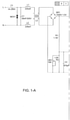
- FIG. 1 illustrates a diagram of a circuit 100 of a typical LED light source.
- the circuit diagram 100 includes various portions or modules that comprise the current control loops, e.g., an LED-current control loop.
- a portion 102 provides over voltage protection that includes a zener diode ZD1.
- a portion 104 provides a current feedback that includes a resistor R13 and an amplifier U2:A.
- a portion 106 provides an over temperature control that includes an amplifier U2:B, capacitor C11 and a transistor Q2.
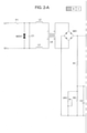
- FIG. 2 illustrates a diagram of a circuit 200 of an LED circuit without a current control loop, e.g., an LED-current control loop, according to the present invention. It should be noted that the circuit 200 is only one way to achieve constant input impedance to allow LED luminaires to be connected in series. It should be noted that other designs may be used to achieve a constant input impedance.
- the circuit 200 is without the current control loop illustrated in the circuit 100. In other words, the current control loop is absent from the circuit 200. Said another way, the circuit 200 does not have a current control loop or any type of current regulator monitoring the LED circuit current.
- the circuit 200 comprises a power factor correction control integrated circuit (IC) 202 having a plurality of pins labeled 1-8. Notably, the circuit 200 directly connects a feedback pin (pin 1) to the return through a resistor R3, thus, disabling the current control loop. Unlike the circuit 100, the circuit 200 does not include the over voltage protection, LED current feedback or the over temperature control.
- IC power factor correction control integrated circuit
- the LED current (at a given supply voltage) is set by resistors R1, R2 and VR1, which drive the input-current wave-shape programming pin, pin 3.
- the supply voltage (which can vary) is the reference determining the LED current in the present circuit 200.
- the LED current may now be set by the input voltage, thus, achieving the desired constant input impedance.
- the peak current in the switching FET Q1 is limited by means of current sense resistor R9 and the peak current sense pin, pin 4. This determines how much power is transferred through the transformer to the LEDs, so limiting their current.
- the pin 1 does not connect directly to any LEDs. Normally, the pin 1 would be used to sense a voltage across a current sense resistor, either directly or indirectly, from a current sense amplifier connected to the LEDs. However, in FIG. 2 , pin 1 is connected to the return so as to disable the constant-LED-current feedback loop, as well as any over voltage or temperature feedback as noted above.
- FIG. 9 illustrates a light system 900 comprising the LED luminaires 300 connected in series.
- a plurality of LED luminaires 300 are connected in series to a power supply 902.
- the circuit 200 is under driven with current. In other words, since there is no longer a current regulation mechanism on the circuit 200, a slightly lower amount of current is driven through the circuit 200 than what the circuit 100 would typically receive or the LED is rated for.
- the circuit 200 maintains power factor correction.
- Power factor correction may be defined as forcing the input current to follow the same shape as the input voltage. In other words, the input current is corrected to form a sine wave when driven from an AC supply. Power factor correction is important for some applications where a company can be penalized by the power generating companies for bad power factor that can generate harmonics that can cause problems for the power generation system.
- the circuit 200 illustrated in FIG. 2 allows the LED luminaires to be connected in series so that the circuit 200 provides a constant input impedance necessary for series connection.
- the LED current is proportional to the input voltage.
- the LED current (and hence the input current) is allowed to vary in proportion to the supply voltage. It should be noted that although one way to achieve this goal is by removing the current control loop as illustrated in FIG. 2 , other methods may be employed to achieve this goal to allow LED luminaires to be connected in series.
- FIG. 3 illustrates an exploded isometric view of an LED luminaire 300 having an LED circuit without the current control loop.
- the LED luminaire 300 has a circuit 200 similar to the one illustrated in FIG. 2 .
- the LED luminaire 300 comprises a housing 302, a power supply 306, a heat sink 310 and an outer lens 318.
- the power supply 306 is designed with the circuit 200 illustrated in FIG. 2 . In other words, the power supply 306 does not have a current control loop and provides a constant input impedence.
- the housing 302 may be a Edison base.
- the heat sink 310 may include one or more fins 324 to help dissipate heat away from the LED luminaire 300.
- the LED luminaire 300 is assembled by inserting the power supply 306 into the housing 302.
- the housing 302 may include potting.
- a gasket 304 may be placed in between the housing 302 and the heat sink 310.
- An insulator 308 is placed on top of the power supply 306.
- the insulator 308 may be fabricated from a material such as Mylar ® , for example.
- FIG. 4 illustrates a top view of the power supply 306 inserted into the heat sink 310.
- a semiconductor package 320 e.g., a D2 PAK, of the power supply 306 is in contact with a protruding portion 330 of the heat sink 310.
- the semiconductor package 320 may be bonded to the heat sink 310 via an adhesive or epoxy.
- the power supply 306 is in direct contact with multiple points of an interior volume of the heat sink 310. This helps to quickly dissipate heat out of the LED luminaire 300 and require less potting.
- a thermal backing 314 may be placed on top of the heat sink 310 and under the light engine 316.
- the light engine 316, the thermal backing 314, the heat sink 310, the gasket 304 and the housing 302 may be coupled together via one or more screws 312.
- the outer lens 318 is be coupled to the heat sink 310.
- FIG. 5 illustrates a top view of the light engine 316.
- the light engine 316 includes one or more LEDs 502.
- the one or more LEDs 502 in the light engine 316 may be connected in series or in parallel.
- the light engine 316 may also include one or more alignment slots 504 to properly align the light engine 316 to the heat sink 310.
- FIGs. 6-8 illustrate various views of a vibration damper 600.
- the vibration damper 600 may be optional.
- FIG. 6 illustrates a top view of the vibration damper 600.
- the vibration damper 600 may be fabricated from any type of polymer, e.g., polycarbonate.
- the vibration damper 600 may be coupled to the bottom of the housing 302. The threaded end of the housing 302 may be fed through the opening 602 of the vibration damper 600.
- FIG. 7 illustrates a cross-sectional side view of the optional vibration damper 600.
- FIG. 8 illustrates a bottom view of the vibration damper 600.
- the vibration damper 600 may provide vibration dampening to the LED luminaire 300.
- the vibration damper 600 may provide a more sturdy base to support the weight of the LED luminaire 300 when they are installed in series, e.g., as part of railway lighting system where high vibration levels may occur.
Landscapes
- Engineering & Computer Science (AREA)
- Microelectronics & Electronic Packaging (AREA)
- General Engineering & Computer Science (AREA)
- Physics & Mathematics (AREA)
- Optics & Photonics (AREA)
- Circuit Arrangement For Electric Light Sources In General (AREA)
- Non-Portable Lighting Devices Or Systems Thereof (AREA)
- Electroluminescent Light Sources (AREA)
Claims (5)
- Système de luminaires à diodes électroluminescentes (LED) (900), comprenant :une alimentation électrique (902) ; etune pluralité de luminaires à LED (300) qui sont connectés en série à l'alimentation électrique (902), dans lequel chacun de la pluralité de luminaires à LED (300) comprend :un logement (302) ;un dissipateur de chaleur (310) qui est couplé au logement ;une ou plusieurs LED (502) ;une lentille (318) qui est couplée au dissipateur de chaleur et qui renferme les une ou plusieurs LED (502) ; dans lequel le dissipateur de chaleur est couplé à la lentille au niveau d'une première extrémité du dissipateur de chaleur et est couplé au logement au niveau d'une seconde extrémité opposée du dissipateur de chaleur ;une alimentation électrique de luminaire (306) qui est configurée pour fournir une tension d'alimentation variable aux une ou plusieurs LED (502) et qui est insérée à l'intérieur d'un volume intérieur du dissipateur de chaleur (310), dans lequel l'alimentation électrique de luminaire (306) est alignée et insérée à l'intérieur du dissipateur de chaleur (322) via des fentes (322) du dissipateur de chaleur (310) de telle sorte qu'un module semiconducteur (320) de l'alimentation électrique (306) soit en contact avec une partie faisant saillie (330) du dissipateur de chaleur (310) ; etun isolant (308) qui est placé sur le dessus de l'alimentation électrique de luminaire (306) ;dans lequel l'alimentation électrique de luminaire (306) comprend un circuit intégré de commande de correction de facteur de puissance (202) qui est configuré pour fournir une impédance d'entrée constante en commandant un courant de LED de telle sorte qu'il varie en proportion de la tension d'alimentation, dans lequel les une ou plusieurs LED sont connectées à une sortie du circuit intégré de commande de correction de facteur de puissance (202) ;dans lequel le circuit intégré de commande de correction de facteur de puissance (202) comporte une pluralité de broches et dans lequel une première de la pluralité de broches est connectée à une ou plusieurs résistances (R1, R2, VR1) qui règlent un courant sur la base de la tension d'alimentation qui varie ; etdans lequel une seconde de la pluralité de broches est couplée pour assurer un retour au travers d'une résistance (R3).
- Système de luminaires à LED selon la revendication 1, dans lequel le courant de LED au travers des une ou plusieurs LED (502) présente une valeur de courant plus faible que la valeur de courant nominal pour laquelle chacune des une ou plusieurs LED est conçue.
- Système de luminaires à LED selon la revendication 1, dans lequel l'alimentation électrique de luminaire (306) est en contact direct avec plusieurs points d'un volume intérieur du dissipateur de chaleur (310).
- Système de luminaires à LED selon la revendication 1, dans lequel le système est inclus dans un système d'éclairage ferroviaire.
- Système de luminaires à LED selon la revendication 1, dans lequel une troisième de la pluralité de broches est couplée à une résistance de détection de courant pour limiter un courant de crête dans un transistor à effet de champ de commutation.
Applications Claiming Priority (2)
| Application Number | Priority Date | Filing Date | Title |
|---|---|---|---|
| US13/196,277 US8908403B2 (en) | 2011-08-02 | 2011-08-02 | Light emitting diode luminaire for connection in series |
| PCT/US2012/049205 WO2013019887A1 (fr) | 2011-08-02 | 2012-08-01 | Luminaire à diodes électroluminescentes destiné à être branché en série |
Publications (3)
| Publication Number | Publication Date |
|---|---|
| EP2739902A1 EP2739902A1 (fr) | 2014-06-11 |
| EP2739902A4 EP2739902A4 (fr) | 2016-06-08 |
| EP2739902B1 true EP2739902B1 (fr) | 2022-01-19 |
Family
ID=47626560
Family Applications (1)
| Application Number | Title | Priority Date | Filing Date |
|---|---|---|---|
| EP12819620.1A Active EP2739902B1 (fr) | 2011-08-02 | 2012-08-01 | Luminaire à diodes électroluminescentes destiné à être branché en série |
Country Status (7)
| Country | Link |
|---|---|
| US (1) | US8908403B2 (fr) |
| EP (1) | EP2739902B1 (fr) |
| AU (1) | AU2012290102B2 (fr) |
| BR (1) | BR112014002470A2 (fr) |
| CA (2) | CA2843591C (fr) |
| MX (1) | MX2014001178A (fr) |
| WO (1) | WO2013019887A1 (fr) |
Families Citing this family (3)
| Publication number | Priority date | Publication date | Assignee | Title |
|---|---|---|---|---|
| KR20150063646A (ko) * | 2013-12-02 | 2015-06-10 | 주식회사 케이엠더블유 | 방출 광량비를 조절할 수 있는 엘이디 조명기구 |
| US20150173135A1 (en) * | 2013-12-17 | 2015-06-18 | Liteideas, Llc | System and method of variable resistance led lighting circuit |
| US10251225B2 (en) * | 2015-12-28 | 2019-04-02 | Eaton Intelligent Power Limited | Multi-mode power supply for an LED illumination device |
Family Cites Families (16)
| Publication number | Priority date | Publication date | Assignee | Title |
|---|---|---|---|---|
| US6461019B1 (en) | 1998-08-28 | 2002-10-08 | Fiber Optic Designs, Inc. | Preferred embodiment to LED light string |
| US7931390B2 (en) * | 1999-02-12 | 2011-04-26 | Fiber Optic Designs, Inc. | Jacketed LED assemblies and light strings containing same |
| US6435459B1 (en) * | 1999-10-28 | 2002-08-20 | Dialight Corporation | LED wayside signal for a railway |
| US6465990B2 (en) * | 2001-03-15 | 2002-10-15 | Bensys Corporation | Power factor correction circuit |
| EE04791B1 (et) * | 2004-12-14 | 2007-02-15 | Tallinna Tehnikaülikool | Vahelduvvoolu-alalisvoolu muundurite võimsusteguri korrektsioonimeetod ja muundur meetodi realiseerimiseks |
| US7649327B2 (en) | 2006-05-22 | 2010-01-19 | Permlight Products, Inc. | System and method for selectively dimming an LED |
| US20100109537A1 (en) * | 2006-10-25 | 2010-05-06 | Panasonic Electric Works Co., Ltd. | Led lighting circuit and illuminating apparatus using the same |
| RU2543987C2 (ru) * | 2007-10-09 | 2015-03-10 | Филипс Солид-Стейт Лайтинг Солюшнз Инк. | Сборное осветительное устройство на основе сид для общего освещения |
| US8382329B2 (en) * | 2008-05-15 | 2013-02-26 | Innovx Group Llc | Adjustable beam lamp |
| US7575346B1 (en) * | 2008-07-22 | 2009-08-18 | Sunonwealth Electric Machine Industry Co., Ltd. | Lamp |
| EP2214456A1 (fr) | 2009-01-22 | 2010-08-04 | Nanker(Guang Zhou)Semiconductor Manufacturing Corp. | Circuit de lampe à diodes |
| US20100264737A1 (en) * | 2009-04-21 | 2010-10-21 | Innovative Engineering & Product Development, Inc. | Thermal control for an encased power supply in an led lighting module |
| US20100277067A1 (en) | 2009-04-30 | 2010-11-04 | Lighting Science Group Corporation | Dimmable led luminaire |
| US8305004B2 (en) * | 2009-06-09 | 2012-11-06 | Stmicroelectronics, Inc. | Apparatus and method for constant power offline LED driver |
| US8344657B2 (en) * | 2009-11-03 | 2013-01-01 | Intersil Americas Inc. | LED driver with open loop dimming control |
| TW201207310A (en) * | 2010-08-13 | 2012-02-16 | Foxsemicon Integrated Tech Inc | LED lamp and method for manufacturing a heat sink of the LED lamp |
-
2011
- 2011-08-02 US US13/196,277 patent/US8908403B2/en active Active
-
2012
- 2012-08-01 BR BR112014002470A patent/BR112014002470A2/pt not_active IP Right Cessation
- 2012-08-01 AU AU2012290102A patent/AU2012290102B2/en active Active
- 2012-08-01 CA CA2843591A patent/CA2843591C/fr active Active
- 2012-08-01 CA CA2957973A patent/CA2957973C/fr active Active
- 2012-08-01 MX MX2014001178A patent/MX2014001178A/es active IP Right Grant
- 2012-08-01 WO PCT/US2012/049205 patent/WO2013019887A1/fr not_active Ceased
- 2012-08-01 EP EP12819620.1A patent/EP2739902B1/fr active Active
Also Published As
| Publication number | Publication date |
|---|---|
| BR112014002470A2 (pt) | 2017-02-21 |
| CA2957973C (fr) | 2020-03-24 |
| MX2014001178A (es) | 2014-05-13 |
| EP2739902A1 (fr) | 2014-06-11 |
| US8908403B2 (en) | 2014-12-09 |
| AU2012290102A1 (en) | 2014-02-20 |
| WO2013019887A1 (fr) | 2013-02-07 |
| US20130033176A1 (en) | 2013-02-07 |
| EP2739902A4 (fr) | 2016-06-08 |
| CA2843591C (fr) | 2017-03-28 |
| CA2957973A1 (fr) | 2013-02-07 |
| AU2012290102B2 (en) | 2016-01-21 |
| CA2843591A1 (fr) | 2013-02-07 |
Similar Documents
| Publication | Publication Date | Title |
|---|---|---|
| US10298014B2 (en) | System and method for controlling solid state lamps | |
| KR100996670B1 (ko) | 전자식 안정기 타입의 엘이디 형광등 | |
| CN103238373B (zh) | Led驱动器电路 | |
| US10681782B2 (en) | Dimmable universal voltage LED power supply with regenerating power source circuitry and non-isolated load | |
| US20120268008A1 (en) | LED Circuits and Assemblies | |
| US9726364B1 (en) | Highly efficient LED lighting fixture | |
| EP3329743B1 (fr) | Circuit d'attaque directement en courant alternatif et luminaire | |
| EP2739902B1 (fr) | Luminaire à diodes électroluminescentes destiné à être branché en série | |
| US8492923B2 (en) | Lamp circuit with simplified circuitry complexity | |
| US8937442B1 (en) | Light emitting diode driving circuit structure | |
| US9591706B2 (en) | Universal voltage LED power supply with regenerating power source circuitry, non-isolated load, and 0-10V dimming circuit | |
| CN105794318B (zh) | 动态控制电路 | |
| JP5322849B2 (ja) | 発光ダイオードの駆動回路、それを用いた発光装置および照明装置 | |
| KR20180120394A (ko) | 우회 전력 소모 수단을 이용한 과전압 보호 장치 | |
| KR101645856B1 (ko) | 교류 전구용 엘이디 조명 | |
| US20120081004A1 (en) | Light emitting diode system | |
| JP6423861B2 (ja) | 3段階切り替え式全方向性ledランプ駆動回路 | |
| CN204145853U (zh) | 高压直驱led照明系统 | |
| US20150156835A1 (en) | Ac direct drive led power supply capable of handling overvoltage | |
| CN204806824U (zh) | 照明结构和冰箱 | |
| TWM514174U (zh) | 發光驅動電路及發光裝置 | |
| US20170048948A1 (en) | Ac direct drive led power supply capable of handling overvoltage | |
| HK1105508A1 (en) | Ac light emitting diode and ac led drive methods and apparatus | |
| HK1105508B (en) | Ac light emitting diode and ac led drive methods and apparatus | |
| TW201820934A (zh) | 智慧型led驅動系統 |
Legal Events
| Date | Code | Title | Description |
|---|---|---|---|
| PUAI | Public reference made under article 153(3) epc to a published international application that has entered the european phase |
Free format text: ORIGINAL CODE: 0009012 |
|
| 17P | Request for examination filed |
Effective date: 20140224 |
|
| AK | Designated contracting states |
Kind code of ref document: A1 Designated state(s): AL AT BE BG CH CY CZ DE DK EE ES FI FR GB GR HR HU IE IS IT LI LT LU LV MC MK MT NL NO PL PT RO RS SE SI SK SM TR |
|
| DAX | Request for extension of the european patent (deleted) | ||
| RA4 | Supplementary search report drawn up and despatched (corrected) |
Effective date: 20160509 |
|
| RIC1 | Information provided on ipc code assigned before grant |
Ipc: H05B 33/08 20060101ALI20160502BHEP Ipc: F21V 23/02 20060101AFI20160502BHEP |
|
| STAA | Information on the status of an ep patent application or granted ep patent |
Free format text: STATUS: EXAMINATION IS IN PROGRESS |
|
| 17Q | First examination report despatched |
Effective date: 20181010 |
|
| GRAP | Despatch of communication of intention to grant a patent |
Free format text: ORIGINAL CODE: EPIDOSNIGR1 |
|
| STAA | Information on the status of an ep patent application or granted ep patent |
Free format text: STATUS: GRANT OF PATENT IS INTENDED |
|
| INTG | Intention to grant announced |
Effective date: 20210810 |
|
| GRAS | Grant fee paid |
Free format text: ORIGINAL CODE: EPIDOSNIGR3 |
|
| GRAA | (expected) grant |
Free format text: ORIGINAL CODE: 0009210 |
|
| STAA | Information on the status of an ep patent application or granted ep patent |
Free format text: STATUS: THE PATENT HAS BEEN GRANTED |
|
| AK | Designated contracting states |
Kind code of ref document: B1 Designated state(s): AL AT BE BG CH CY CZ DE DK EE ES FI FR GB GR HR HU IE IS IT LI LT LU LV MC MK MT NL NO PL PT RO RS SE SI SK SM TR |
|
| REG | Reference to a national code |
Ref country code: GB Ref legal event code: FG4D |
|
| REG | Reference to a national code |
Ref country code: CH Ref legal event code: EP |
|
| REG | Reference to a national code |
Ref country code: DE Ref legal event code: R096 Ref document number: 602012077556 Country of ref document: DE |
|
| REG | Reference to a national code |
Ref country code: AT Ref legal event code: REF Ref document number: 1463997 Country of ref document: AT Kind code of ref document: T Effective date: 20220215 |
|
| REG | Reference to a national code |
Ref country code: IE Ref legal event code: FG4D |
|
| REG | Reference to a national code |
Ref country code: LT Ref legal event code: MG9D |
|
| REG | Reference to a national code |
Ref country code: NL Ref legal event code: MP Effective date: 20220119 |
|
| REG | Reference to a national code |
Ref country code: AT Ref legal event code: MK05 Ref document number: 1463997 Country of ref document: AT Kind code of ref document: T Effective date: 20220119 |
|
| PG25 | Lapsed in a contracting state [announced via postgrant information from national office to epo] |
Ref country code: NL Free format text: LAPSE BECAUSE OF FAILURE TO SUBMIT A TRANSLATION OF THE DESCRIPTION OR TO PAY THE FEE WITHIN THE PRESCRIBED TIME-LIMIT Effective date: 20220119 |
|
| PG25 | Lapsed in a contracting state [announced via postgrant information from national office to epo] |
Ref country code: SE Free format text: LAPSE BECAUSE OF FAILURE TO SUBMIT A TRANSLATION OF THE DESCRIPTION OR TO PAY THE FEE WITHIN THE PRESCRIBED TIME-LIMIT Effective date: 20220119 Ref country code: RS Free format text: LAPSE BECAUSE OF FAILURE TO SUBMIT A TRANSLATION OF THE DESCRIPTION OR TO PAY THE FEE WITHIN THE PRESCRIBED TIME-LIMIT Effective date: 20220119 Ref country code: PT Free format text: LAPSE BECAUSE OF FAILURE TO SUBMIT A TRANSLATION OF THE DESCRIPTION OR TO PAY THE FEE WITHIN THE PRESCRIBED TIME-LIMIT Effective date: 20220519 Ref country code: NO Free format text: LAPSE BECAUSE OF FAILURE TO SUBMIT A TRANSLATION OF THE DESCRIPTION OR TO PAY THE FEE WITHIN THE PRESCRIBED TIME-LIMIT Effective date: 20220419 Ref country code: LT Free format text: LAPSE BECAUSE OF FAILURE TO SUBMIT A TRANSLATION OF THE DESCRIPTION OR TO PAY THE FEE WITHIN THE PRESCRIBED TIME-LIMIT Effective date: 20220119 Ref country code: HR Free format text: LAPSE BECAUSE OF FAILURE TO SUBMIT A TRANSLATION OF THE DESCRIPTION OR TO PAY THE FEE WITHIN THE PRESCRIBED TIME-LIMIT Effective date: 20220119 Ref country code: ES Free format text: LAPSE BECAUSE OF FAILURE TO SUBMIT A TRANSLATION OF THE DESCRIPTION OR TO PAY THE FEE WITHIN THE PRESCRIBED TIME-LIMIT Effective date: 20220119 Ref country code: BG Free format text: LAPSE BECAUSE OF FAILURE TO SUBMIT A TRANSLATION OF THE DESCRIPTION OR TO PAY THE FEE WITHIN THE PRESCRIBED TIME-LIMIT Effective date: 20220419 |
|
| PG25 | Lapsed in a contracting state [announced via postgrant information from national office to epo] |
Ref country code: PL Free format text: LAPSE BECAUSE OF FAILURE TO SUBMIT A TRANSLATION OF THE DESCRIPTION OR TO PAY THE FEE WITHIN THE PRESCRIBED TIME-LIMIT Effective date: 20220119 Ref country code: LV Free format text: LAPSE BECAUSE OF FAILURE TO SUBMIT A TRANSLATION OF THE DESCRIPTION OR TO PAY THE FEE WITHIN THE PRESCRIBED TIME-LIMIT Effective date: 20220119 Ref country code: GR Free format text: LAPSE BECAUSE OF FAILURE TO SUBMIT A TRANSLATION OF THE DESCRIPTION OR TO PAY THE FEE WITHIN THE PRESCRIBED TIME-LIMIT Effective date: 20220420 Ref country code: FI Free format text: LAPSE BECAUSE OF FAILURE TO SUBMIT A TRANSLATION OF THE DESCRIPTION OR TO PAY THE FEE WITHIN THE PRESCRIBED TIME-LIMIT Effective date: 20220119 Ref country code: AT Free format text: LAPSE BECAUSE OF FAILURE TO SUBMIT A TRANSLATION OF THE DESCRIPTION OR TO PAY THE FEE WITHIN THE PRESCRIBED TIME-LIMIT Effective date: 20220119 |
|
| PG25 | Lapsed in a contracting state [announced via postgrant information from national office to epo] |
Ref country code: IS Free format text: LAPSE BECAUSE OF FAILURE TO SUBMIT A TRANSLATION OF THE DESCRIPTION OR TO PAY THE FEE WITHIN THE PRESCRIBED TIME-LIMIT Effective date: 20220519 |
|
| REG | Reference to a national code |
Ref country code: DE Ref legal event code: R097 Ref document number: 602012077556 Country of ref document: DE |
|
| PG25 | Lapsed in a contracting state [announced via postgrant information from national office to epo] |
Ref country code: SM Free format text: LAPSE BECAUSE OF FAILURE TO SUBMIT A TRANSLATION OF THE DESCRIPTION OR TO PAY THE FEE WITHIN THE PRESCRIBED TIME-LIMIT Effective date: 20220119 Ref country code: SK Free format text: LAPSE BECAUSE OF FAILURE TO SUBMIT A TRANSLATION OF THE DESCRIPTION OR TO PAY THE FEE WITHIN THE PRESCRIBED TIME-LIMIT Effective date: 20220119 Ref country code: RO Free format text: LAPSE BECAUSE OF FAILURE TO SUBMIT A TRANSLATION OF THE DESCRIPTION OR TO PAY THE FEE WITHIN THE PRESCRIBED TIME-LIMIT Effective date: 20220119 Ref country code: EE Free format text: LAPSE BECAUSE OF FAILURE TO SUBMIT A TRANSLATION OF THE DESCRIPTION OR TO PAY THE FEE WITHIN THE PRESCRIBED TIME-LIMIT Effective date: 20220119 Ref country code: DK Free format text: LAPSE BECAUSE OF FAILURE TO SUBMIT A TRANSLATION OF THE DESCRIPTION OR TO PAY THE FEE WITHIN THE PRESCRIBED TIME-LIMIT Effective date: 20220119 Ref country code: CZ Free format text: LAPSE BECAUSE OF FAILURE TO SUBMIT A TRANSLATION OF THE DESCRIPTION OR TO PAY THE FEE WITHIN THE PRESCRIBED TIME-LIMIT Effective date: 20220119 |
|
| PLBE | No opposition filed within time limit |
Free format text: ORIGINAL CODE: 0009261 |
|
| STAA | Information on the status of an ep patent application or granted ep patent |
Free format text: STATUS: NO OPPOSITION FILED WITHIN TIME LIMIT |
|
| PG25 | Lapsed in a contracting state [announced via postgrant information from national office to epo] |
Ref country code: AL Free format text: LAPSE BECAUSE OF FAILURE TO SUBMIT A TRANSLATION OF THE DESCRIPTION OR TO PAY THE FEE WITHIN THE PRESCRIBED TIME-LIMIT Effective date: 20220119 |
|
| 26N | No opposition filed |
Effective date: 20221020 |
|
| PG25 | Lapsed in a contracting state [announced via postgrant information from national office to epo] |
Ref country code: SI Free format text: LAPSE BECAUSE OF FAILURE TO SUBMIT A TRANSLATION OF THE DESCRIPTION OR TO PAY THE FEE WITHIN THE PRESCRIBED TIME-LIMIT Effective date: 20220119 |
|
| PG25 | Lapsed in a contracting state [announced via postgrant information from national office to epo] |
Ref country code: MC Free format text: LAPSE BECAUSE OF FAILURE TO SUBMIT A TRANSLATION OF THE DESCRIPTION OR TO PAY THE FEE WITHIN THE PRESCRIBED TIME-LIMIT Effective date: 20220119 |
|
| REG | Reference to a national code |
Ref country code: CH Ref legal event code: PL |
|
| PG25 | Lapsed in a contracting state [announced via postgrant information from national office to epo] |
Ref country code: LU Free format text: LAPSE BECAUSE OF NON-PAYMENT OF DUE FEES Effective date: 20220801 Ref country code: LI Free format text: LAPSE BECAUSE OF NON-PAYMENT OF DUE FEES Effective date: 20220831 Ref country code: CH Free format text: LAPSE BECAUSE OF NON-PAYMENT OF DUE FEES Effective date: 20220831 |
|
| REG | Reference to a national code |
Ref country code: BE Ref legal event code: MM Effective date: 20220831 |
|
| P01 | Opt-out of the competence of the unified patent court (upc) registered |
Effective date: 20230524 |
|
| PG25 | Lapsed in a contracting state [announced via postgrant information from national office to epo] |
Ref country code: IT Free format text: LAPSE BECAUSE OF FAILURE TO SUBMIT A TRANSLATION OF THE DESCRIPTION OR TO PAY THE FEE WITHIN THE PRESCRIBED TIME-LIMIT Effective date: 20220119 Ref country code: IE Free format text: LAPSE BECAUSE OF NON-PAYMENT OF DUE FEES Effective date: 20220801 |
|
| PG25 | Lapsed in a contracting state [announced via postgrant information from national office to epo] |
Ref country code: BE Free format text: LAPSE BECAUSE OF NON-PAYMENT OF DUE FEES Effective date: 20220831 |
|
| PG25 | Lapsed in a contracting state [announced via postgrant information from national office to epo] |
Ref country code: HU Free format text: LAPSE BECAUSE OF FAILURE TO SUBMIT A TRANSLATION OF THE DESCRIPTION OR TO PAY THE FEE WITHIN THE PRESCRIBED TIME-LIMIT; INVALID AB INITIO Effective date: 20120801 |
|
| PG25 | Lapsed in a contracting state [announced via postgrant information from national office to epo] |
Ref country code: MK Free format text: LAPSE BECAUSE OF FAILURE TO SUBMIT A TRANSLATION OF THE DESCRIPTION OR TO PAY THE FEE WITHIN THE PRESCRIBED TIME-LIMIT Effective date: 20220119 Ref country code: CY Free format text: LAPSE BECAUSE OF FAILURE TO SUBMIT A TRANSLATION OF THE DESCRIPTION OR TO PAY THE FEE WITHIN THE PRESCRIBED TIME-LIMIT Effective date: 20220119 |
|
| PG25 | Lapsed in a contracting state [announced via postgrant information from national office to epo] |
Ref country code: MT Free format text: LAPSE BECAUSE OF FAILURE TO SUBMIT A TRANSLATION OF THE DESCRIPTION OR TO PAY THE FEE WITHIN THE PRESCRIBED TIME-LIMIT Effective date: 20220119 |
|
| PGFP | Annual fee paid to national office [announced via postgrant information from national office to epo] |
Ref country code: DE Payment date: 20250709 Year of fee payment: 14 |
|
| PGFP | Annual fee paid to national office [announced via postgrant information from national office to epo] |
Ref country code: GB Payment date: 20250710 Year of fee payment: 14 |
|
| PGFP | Annual fee paid to national office [announced via postgrant information from national office to epo] |
Ref country code: FR Payment date: 20250709 Year of fee payment: 14 |
|
| PG25 | Lapsed in a contracting state [announced via postgrant information from national office to epo] |
Ref country code: TR Free format text: LAPSE BECAUSE OF FAILURE TO SUBMIT A TRANSLATION OF THE DESCRIPTION OR TO PAY THE FEE WITHIN THE PRESCRIBED TIME-LIMIT Effective date: 20220119 |