EP2740153B1 - Dispositif de refroidissement muni d'un capteur thermoelectrique - Google Patents
Dispositif de refroidissement muni d'un capteur thermoelectrique Download PDFInfo
- Publication number
- EP2740153B1 EP2740153B1 EP12758526.3A EP12758526A EP2740153B1 EP 2740153 B1 EP2740153 B1 EP 2740153B1 EP 12758526 A EP12758526 A EP 12758526A EP 2740153 B1 EP2740153 B1 EP 2740153B1
- Authority
- EP
- European Patent Office
- Prior art keywords
- channel
- component
- cooling
- thermoelectric module
- control circuit
- Prior art date
- Legal status (The legal status is an assumption and is not a legal conclusion. Google has not performed a legal analysis and makes no representation as to the accuracy of the status listed.)
- Not-in-force
Links
Images


Classifications
-
- H—ELECTRICITY
- H05—ELECTRIC TECHNIQUES NOT OTHERWISE PROVIDED FOR
- H05K—PRINTED CIRCUITS; CASINGS OR CONSTRUCTIONAL DETAILS OF ELECTRIC APPARATUS; MANUFACTURE OF ASSEMBLAGES OF ELECTRICAL COMPONENTS
- H05K7/00—Constructional details common to different types of electric apparatus
- H05K7/20—Modifications to facilitate cooling, ventilating, or heating
- H05K7/20218—Modifications to facilitate cooling, ventilating, or heating using a liquid coolant without phase change in electronic enclosures
- H05K7/20281—Thermal management, e.g. liquid flow control
-
- G—PHYSICS
- G06—COMPUTING OR CALCULATING; COUNTING
- G06F—ELECTRIC DIGITAL DATA PROCESSING
- G06F1/00—Details not covered by groups G06F3/00 - G06F13/00 and G06F21/00
- G06F1/16—Constructional details or arrangements
- G06F1/20—Cooling means
- G06F1/206—Cooling means comprising thermal management
-
- H—ELECTRICITY
- H10—SEMICONDUCTOR DEVICES; ELECTRIC SOLID-STATE DEVICES NOT OTHERWISE PROVIDED FOR
- H10W—GENERIC PACKAGES, INTERCONNECTIONS, CONNECTORS OR OTHER CONSTRUCTIONAL DETAILS OF DEVICES COVERED BY CLASS H10
- H10W40/00—Arrangements for thermal protection or thermal control
-
- H—ELECTRICITY
- H10—SEMICONDUCTOR DEVICES; ELECTRIC SOLID-STATE DEVICES NOT OTHERWISE PROVIDED FOR
- H10W—GENERIC PACKAGES, INTERCONNECTIONS, CONNECTORS OR OTHER CONSTRUCTIONAL DETAILS OF DEVICES COVERED BY CLASS H10
- H10W40/00—Arrangements for thermal protection or thermal control
- H10W40/20—Arrangements for cooling
- H10W40/25—Arrangements for cooling characterised by their materials
- H10W40/251—Organics
-
- H—ELECTRICITY
- H10—SEMICONDUCTOR DEVICES; ELECTRIC SOLID-STATE DEVICES NOT OTHERWISE PROVIDED FOR
- H10W—GENERIC PACKAGES, INTERCONNECTIONS, CONNECTORS OR OTHER CONSTRUCTIONAL DETAILS OF DEVICES COVERED BY CLASS H10
- H10W40/00—Arrangements for thermal protection or thermal control
- H10W40/20—Arrangements for cooling
- H10W40/28—Arrangements for cooling comprising Peltier coolers
-
- H—ELECTRICITY
- H10—SEMICONDUCTOR DEVICES; ELECTRIC SOLID-STATE DEVICES NOT OTHERWISE PROVIDED FOR
- H10W—GENERIC PACKAGES, INTERCONNECTIONS, CONNECTORS OR OTHER CONSTRUCTIONAL DETAILS OF DEVICES COVERED BY CLASS H10
- H10W40/00—Arrangements for thermal protection or thermal control
- H10W40/40—Arrangements for thermal protection or thermal control involving heat exchange by flowing fluids
-
- H—ELECTRICITY
- H10—SEMICONDUCTOR DEVICES; ELECTRIC SOLID-STATE DEVICES NOT OTHERWISE PROVIDED FOR
- H10W—GENERIC PACKAGES, INTERCONNECTIONS, CONNECTORS OR OTHER CONSTRUCTIONAL DETAILS OF DEVICES COVERED BY CLASS H10
- H10W40/00—Arrangements for thermal protection or thermal control
- H10W40/40—Arrangements for thermal protection or thermal control involving heat exchange by flowing fluids
- H10W40/47—Arrangements for thermal protection or thermal control involving heat exchange by flowing fluids by flowing liquids, e.g. forced water cooling
-
- Y—GENERAL TAGGING OF NEW TECHNOLOGICAL DEVELOPMENTS; GENERAL TAGGING OF CROSS-SECTIONAL TECHNOLOGIES SPANNING OVER SEVERAL SECTIONS OF THE IPC; TECHNICAL SUBJECTS COVERED BY FORMER USPC CROSS-REFERENCE ART COLLECTIONS [XRACs] AND DIGESTS
- Y02—TECHNOLOGIES OR APPLICATIONS FOR MITIGATION OR ADAPTATION AGAINST CLIMATE CHANGE
- Y02D—CLIMATE CHANGE MITIGATION TECHNOLOGIES IN INFORMATION AND COMMUNICATION TECHNOLOGIES [ICT], I.E. INFORMATION AND COMMUNICATION TECHNOLOGIES AIMING AT THE REDUCTION OF THEIR OWN ENERGY USE
- Y02D10/00—Energy efficient computing, e.g. low power processors, power management or thermal management
Definitions
- the invention relates to the thermal management of components, and more particularly to a cooling device provided with a heat transfer fluid in circulation.
- Passive cooling devices use a radiator or thermal via to remove heat from the components to the outside.
- the use of a radiator is constraining for the integration of the electronic system in a small device, such as a mobile phone.
- High performance thermal via, for example carbon nanotubes, are difficult to manufacture and complexify the architecture of the system.
- Passive devices may be associated with air ventilation to improve cooling performance.
- a circulating coolant should be used.
- the figure 1 schematically represents an electronic system cooled by a circulating liquid, as described in the patent application US2010 / 0290188 .
- the electronic system is formed of a stack of integrated circuits 2.
- the stack is fixed to a printed circuit board 4 by means of solder balls 6.
- the circuits 2 are interconnected by metal pins 8, formed in pads 10 in silicon.
- the integrated circuits 2 of the stack are spaced apart from each other by means of the interconnection pads 10. These spacings allow the circulation of a coolant 12.
- the liquid 12 also circulates between the upper circuit 2 and a wall a housing 14 serving as a liquid containment structure.
- the housing 14 comprises an inlet port 16a and an outlet orifice 16b of the coolant, disposed on either side of the stack.
- the flow of liquid 12, generated by a pump circulates in contact with the circuits 2 from one end to the other of the housing 14.
- the control of the flow of coolant is provided by the pump.
- the flow rate is usually set to a high value to ensure maximum cooling whatever the thermal conditions of the system. This control does not take into account the actual need for cooling at the component level.
- the liquid consumption, and therefore the power consumption of the pump, are not optimized.
- the document US5966940 discloses a device for managing the temperature of a semiconductor component.
- the component is disposed on a thermal plate containing a temperature sensor, for example a thermocouple operating in a Peltier mode.
- the sensor is installed in the hot zone.
- the document JP S6138381 deals with a cooling device provided with two thermometers configured to respectively measure the ambient temperature and the temperature of the coolant.
- the cooling device is configured to prevent condensation on the cooling circuit.
- thermoelectric module comprises several thermoelectric elements.
- a device for cooling a component comprising at least one channel in which circulates a first heat transfer fluid for cooling a hot zone of the component.
- the device comprises a thermoelectric module configured to measure a temperature difference between the hot zone of the component and the channel, and a control circuit configured to modulate the flow of the first heat transfer fluid in the channel as a function of the temperature difference.
- the surface of the channel in contact with the first heat transfer fluid is covered with a layer of polymer material having a first surface energy under a first excitation condition and a second surface energy under a second condition. excitation, the first and second excitation conditions being set by the control circuit.
- the layer of polymer material is a self-assembled monolayer comprising mercapto-hexadecanoic acid particles and the thermoelectric module is configured to apply a temperature variation to the self-assembled monolayer representative of the first and second conditions of excitation.
- the layer of polymer material comprises isopropylacrylamide monomers and the control circuit is configured to apply a variation of electrical potential to the layer of polymer material representative of the first and second excitation conditions.
- thermoelectric sensor In order to optimize the heat transfer fluid flow rate in a cooling circuit, a thermoelectric sensor is provided between the cooling circuit and a hot zone of a component to be cooled. This sensor measures the characteristics of the thermal environment of the component, in particular the temperature difference between the component and the coolant. The sensor is coupled to a control circuit that regulates the heat transfer fluid flow as a function of this temperature difference. The flow rate of the fluid is thus continuously adapted to the cooling needs of the component.
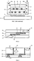
- the figure 2 represents an embodiment of cooling device provided with a thermoelectric module.
- the cooling device comprises a cooling circuit 18 and a thermoelectric module 20, disposed between the circuit 18 and a hot zone 22 of the component.
- the cooling circuit 18 comprises at least one channel or heat pipe in which circulates the coolant.
- the circuit 18 is formed of a network of channels.
- thermoelectric module 20 is in thermal contact with the channel network 18, forming a cold source, and a second end is in thermal contact with the hot source 22.
- the thermoelectric module 20 is thus subjected to a temperature difference at its ends. It is further electrically connected to a control circuit (not shown on the figure 2 ).
- the cooling device is integrated with the component to be cooled.
- the component is formed of an integrated circuit stack 24, each integrated circuit having a hot zone 22.
- the integrated circuits 24 are conventionally separated by an interconnection layer 26 containing metal via. These via electrically connect the integrated circuits 24.
- the cooling circuit 18 and the thermoelectric module 20 are preferably formed in the interconnection layer 26.
- thermoelectric module As shown on the figure 2 the same network of channels 18 can participate in the cooling of several hot zones 22, each zone 22 being separated from the network 18 by a thermoelectric module.
- the cooling device comprises a plurality of cooling circuits and several thermoelectric modules, distributed in different levels of the stack. It is then possible to individually cool each integrated circuit of the stack.
- the cooling circuits can be independent or connected to form a single heat transfer fluid distribution network.
- the heat transfer fluid is a gas or a liquid at a temperature lower than that of the component in the hot zone. It is preferably selected from water, nitrogen and an alcohol.
- the figure 3 represents an alternative embodiment of cooling device, in which the cooling circuit is remote from the component.
- the device comprises a cooling layer 28, in which the channels 18 are formed, and at least one thermoelectric module 20 formed on the layer 28.
- the layer 28 and the module 20 are surmounted by at least one component 24 to be cooled.
- the component 24 comprises two hot spots 22, each associated with a set of channels 18 and a module 20.
- One end of each module 20 is in thermal contact with the channels 18.
- the other end is in thermal contact with a point 22, preferably via a thermal via 30 (also called thermal bridge).
- the thermal vias 30 are formed of a material having a high thermal conductivity, preferably greater than the thermal conductivity of the material forming the component 24.
- the vias 30 are, for example, formed of a metal. In this case, the via 30 can make the electrical connection of the thermoelectric modules 20 to the control circuit, arranged for example above the component 24 or on the same substrate as that of the component 24.
- the layer 28 constitutes a support in which the fluid circuit is formed.
- This support is, for example, silicon and may further serve to form the control circuit.
- the layer 28 may also be formed of a thermal insulating material such as glass.
- a cooling layer 28, covered with thermoelectric modules 20, can be used to cool several stacked components 24.
- this variant of the cooling device is particularly simple to implement. The cooling device and the component can be manufactured separately and then the component is attached to the cooling device.
- the figure 4 represents a block diagram of the cooling device of the Figures 2 and 3 , coupled to a component 24.
- the black arrows represent the electrical signals received and sent by the various elements of the device while the white arrows represent the flow of heat.
- thermoelectric module 20 measures the temperature difference between the component 24 and the cooling circuit 18.
- An electrical signal representative of this difference for example the voltage at the ends of the module 20, is transmitted to the control circuit 32.
- the control circuit 32 controls the cooling circuit 18 so as to modify the flow of the coolant as a function of the temperature difference .
- the heat of the component is largely evacuated by the network of channels 18. This heat transfer is carried out by thermal conduction of the various layers separating the hot zone 22 and the channel network 18.
- thermoelectric module 20 also participates in cooling the component. Indeed, a portion of the heat flow passes through the thermoelectric material, from the hot source 22 to the cold source 18. This transfer is however limited because of the small volume occupied by the thermoelectric module and the low thermal conductivity of the materials which the up.
- the control circuit 32 comprises, for example, an amplifier of the measurement signal, at the output of the thermoelectric sensor 20, a processing algorithm in the form of a microprocessor and a circuit for generating the control signals.
- the control circuit receives and processes all the measurement signals, for example simultaneously.
- the figure 5 represents examples of cooling circuit for modulating the heat transfer fluid flow.
- the cooling circuit has been simplified: it is formed of a single channel 18 of trapezoidal section.
- the coolant flow 12 is modulated by varying the surface energy between the channel 18 and the fluid 12.
- the surface of the channel in contact with the fluid is covered with a layer in polymeric material 34.
- the control circuit sends an electrical or thermal stimulus to the layer 34.
- This modifies the internal structure of the polymer layer 34 and therefore its surface energy. In the case of water as heat transfer fluid, this amounts to modifying the wettability of the channel surface, that is to say its hydrophilic or hydrophobic character.
- control circuit 32 defines excitation conditions, to pass the polymer layer 34 from a first state to a second state, the surface energy of the polymer being different between the two states.
- the polymer layer is, for example, a self-assembled monolayer (SAM) as described in the article.
- SAM self-assembled monolayer
- MHA mercapto-hexadecanoic acid
- the polymer layer comprises monomers of N-isopropylacrylamide (PNIPAM), described in the article "A reversible Switching Surface". These monomers are temperature sensitive.
- the polymer layer becomes hydrophobic by heating it above a given temperature, of the order of 32 ° C. On the contrary, it becomes hydrophilic by cooling it below this temperature.
- Some of these molecules are grafted onto a particular type of surface to form a SAM self-assembly monolayer.
- the channel 18 is then formed in a material allowing the grafting of the molecules used, for example gold in the case of MHA molecules.
- the electrical stimulus is preferably transmitted by the thermoelectric module to the polymer layer.
- the thermoelectric module is electrically connected to the control circuit.
- the control circuit can therefore send an electrical signal to the polymer layer, via the thermoelectric module (arrow in broken lines on the figure 4 ).
- thermoelectric module directly discharges a portion of the heat flow to the cooling circuit. This heat transfer can therefore be used to locally modify the structure of the polymer layer.
- thermoelectric module in direct contact with the channel, transmits the thermal information causing the modification of the polymer layer.
- the surface of the channel 18 covered with polymeric material depends on the maximum variation of flow envisaged.
- the polymer layer 34 may be deposited on the entire surface of the channel 18 ( Fig.5 ).
- the fluid will then be directed to another branch of the cooling circuit, to evacuate the heat of another component.
- the polymer material can be deposited on a single wall of the channel 18 when it is desired to vary the flow rate to a lesser extent.
- the polymer layer 34 is preferably deposited on the channel 18 in the vicinity of the thermoelectric module 20. It may also be disposed upstream or downstream of the thermoelectric module in the fluid flow direction. An additional thermal or electrical conductor, distinct from a thermoelectric module, is then provided for conveying the associated signal.
- the surface of the channel 18 in contact with the fluid 12 is advantageously structured in order to carry out a more precise control of the surface energy.
- the cooling device described above allows the use of a closed cooling circuit 18. Indeed, by modifying the surface energy locally, in several consecutive zones of the circuit 18, it is possible to create a movement of the coolant.
- a closed circuit is particularly interesting for nomadic applications. Indeed, it is then dispensed with a pump to force the circulation of heat transfer fluid, which represents a gain in consumption and a saving of space.
- the control circuit 32 may also control an introduction valve connected to a reservoir of an additional heat transfer fluid.
- This second heat transfer fluid preferably has a thermal capacity different from that of the first fluid.
- the second fluid when introduced into the circuit 18, it increases or decreases the cooling capacity (or heat value) of the first heat transfer fluid.
- the two fluids are chosen to trigger an endothermic reaction when they are mixed. They are preferably conveyed by separate channels and then mixed at the thermoelectric module.
- Article Microfluidic Bubble Logic (Prakash et al., Science, Vol 315, pp. 832-835, Feb. 2007) ) describes an example of a fluid system for such a mixture.
- the Figures 6 to 8 represent steps of a method of producing a cooling device according to the figure 3 .
- the stage of figure 6 corresponds to the formation of the cooling layer 28 containing the channels 18.
- the channels are preferably etched in a silicon substrate. They have, for example, a cylindrical shape and a diameter of between 10 microns and 1 mm.
- the surface of the channels 18 in contact with the coolant is, if necessary, covered with a thin layer of gold, aluminum or titanium, 10 nm to 100 ⁇ m thick, before depositing the polymeric material.
- the thickness of the polymer layer varies between 10 nm and 1 ⁇ m.
- thermoelectric module 20 is formed on the surface of the cooling layer 28. One end of the module 20 is disposed in contact with the channels 18.
- thermoelectric module 20 is advantageously formed of a plurality of thermocouples.
- Each thermocouple comprises two thermoelectric pads 36a and 36b connected together at one of their ends by an internal metal connector 38.
- the thermocouples are electrically connected in series by means of metal connectors 40.
- the pads 36a and 36b have different thermoelectric natures.
- the stud 36a is made of P-type silicon and the stud 36b is made of N-type silicon.
- Other materials, semi-conductors or semi-metals, can be envisaged, such as germanium, bismuth, antimony and their alloys.
- the pads 36a and 36b are preferably of identical dimensions. Their thickness is, for example, between 5 nm and 500 microns according to the production method used.
- the component 24 is then glued on the cooling device ( Fig.8 ). It preferably comprises metal vias 30 for conducting heat from the hot zone 22, located inside the component, to the thermoelectric module 20.
- connection connectors 40 are in contact with the metal via 30, individually so as not to form a short circuit.
- the internal connectors 36 are arranged on the channels 18. The thermocouples are thus arranged in parallel between a hot source formed by the component and a cold source formed by the channels 18.
- the temperature (cold) of the coolant increases.
- the regulation of the flow (and / or the modulation of the thermal capacity of the fluid), provided by the control circuit makes it possible, however, to maintain the temperature of the cold source at a suitable value.
- the signal delivered by the thermoelectric sensor reflects, at each moment, the thermal conditions in which the component is located.
- thermoelectric module makes it possible to follow the evolution of the temperature of the component and to adapt in real time the flow and the path of the coolant.
- the consumption of the fluid can then be limited to the need of the component. Since the fluid flow rate is generally imposed by a pump, this represents a saving of electrical energy.
- the thermoelectric module does not consume current since it functions as a temperature sensor, and not in Peltier mode. We then obtain a cooling device having a lower power consumption than those of conventional active devices.
- a closed cooling circuit that is to say without a pump, will be preferred.
- the electrical consumption of the cooling device will then be minimal and will correspond to that of the control circuit.
Landscapes
- Engineering & Computer Science (AREA)
- Theoretical Computer Science (AREA)
- Physics & Mathematics (AREA)
- Microelectronics & Electronic Packaging (AREA)
- Human Computer Interaction (AREA)
- General Engineering & Computer Science (AREA)
- General Physics & Mathematics (AREA)
- Thermal Sciences (AREA)
- Cooling Or The Like Of Semiconductors Or Solid State Devices (AREA)
- Cooling Or The Like Of Electrical Apparatus (AREA)
- Chemical & Material Sciences (AREA)
- Materials Engineering (AREA)
Description
- L'invention est relative à la gestion thermique de composants, et plus particulièrement à un dispositif de refroidissement muni d'un fluide caloporteur en circulation.
- L'intégration massive de composants dans les systèmes électroniques pose inévitablement le problème du refroidissement. En effet, plus les composants sont nombreux dans un volume donné, plus le système électronique chauffe et plus le risque de détérioration due à une surchauffe est important.
- Il existe différentes solutions de refroidissement. Les dispositifs de refroidissement passifs utilisent un radiateur ou des via thermiques pour évacuer la chaleur des composants vers l'extérieur. L'utilisation d'un radiateur est contraignante pour l'intégration du système électronique dans un appareil de taille réduite, tel qu'un téléphone portable. Les via thermiques performants, par exemple en nanotubes de carbone, sont difficiles à fabriquer et complexifient l'architecture du système.
- Les dispositifs passifs peuvent être associés à une ventilation d'air afin d'améliorer les performances de refroidissement. Lorsque la convection d'air, naturelle ou forcée, n'est plus suffisante pour évacuer l'énergie dissipée par le système, il convient d'utiliser un liquide de refroidissement en circulation.
- La
figure 1 représente schématiquement un système électronique refroidi par un liquide en circulation, tel que décrit dans la demande de brevetUS2010/0290188 . - Le système électronique est formé d'un empilement de circuits intégrés 2. L'empilement est fixé à un circuit imprimé 4 à l'aide de billes de soudure 6. Les circuits 2 sont interconnectés par des via métalliques 8, formés dans des plots 10 en silicium.
- Les circuits intégrés 2 de l'empilement sont espacés entre eux, à l'aide des plots d'interconnexion 10. Ces espacements permettent la circulation d'un liquide de refroidissement 12. Le liquide 12 circule également entre le circuit 2 supérieur et une paroi d'un boîtier 14 servant de structure de confinement au liquide. Le boîtier 14 comprend un orifice d'entrée 16a et un orifice de sortie 16b du liquide de refroidissement, disposés de part et d'autre de l'empilement. Ainsi, le flux de liquide 12, généré par une pompe, circule en contact des circuits 2 d'une extrémité à l'autre du boîtier 14.
- Dans ce type de système, le contrôle du débit du liquide de refroidissement est assuré par la pompe. Le débit est généralement fixé à une valeur élevée pour assurer un refroidissement maximal quelles que soient les conditions thermiques du système. Ce contrôle ne tient pas compte du besoin réel de refroidissement au niveau des composants. La consommation de liquide, et donc la consommation électrique de la pompe, ne sont pas optimisées.
- Le document
US5966940 divulgue un dispositif de gestion de la température d'un composant semi-conducteur. Le composant est disposé sur une plaque thermique contenant un capteur de température, par exemple un thermocouple fonctionnant ne mode Peltier. Le capteur est installé dans la zone chaude. - Le document
JP S6138381 - Le document
JP 2005117835 - On constate qu'il existe un besoin de prévoir un dispositif permettant un refroidissement optimisé tout en ayant une consommation électrique et fluidique réduite.
- On tend à satisfaire ce besoin en prévoyant un dispositif de refroidissement d'un composant comprenant au moins un canal dans lequel circule un premier fluide caloporteur destiné à refroidir une zone chaude du composant. Le dispositif comporte un module thermoélectrique configuré pour mesurer une différence de température entre la zone chaude du composant et le canal, et un circuit de contrôle configuré pour moduler le débit du premier fluide caloporteur dans le canal en fonction de la différence de température.
- Dans un mode de réalisation préférentiel, la surface du canal en contact avec le premier fluide caloporteur est recouverte d'une couche en matériau polymère présentant une première énergie de surface sous une première condition d'excitation et une deuxième énergie de surface sous une deuxième condition d'excitation, les première et deuxième conditions d'excitation étant fixées par le circuit de contrôle.
- Selon un développement, la couche en matériau polymère est une monocouche auto-assemblée comprenant des particules d'acide mercapto-hexadécanoïque et le module thermoélectrique est configuré pour appliquer une variation de température à la monocouche auto-assemblée représentative des première et deuxième conditions d'excitation.
- Selon un autre développement, la couche en matériau polymère comprend des monomères d'isopropylacrylamide et le circuit de contrôle est configuré pour appliquer une variation de potentiel électrique à la couche en matériau polymère représentative des première et deuxième conditions d'excitation.
- D'autres avantages et caractéristiques ressortiront plus clairement de la description qui va suivre de modes particuliers de réalisation donnés à titre d'exemples non limitatifs et illustrés à l'aide des dessins annexés, dans lesquels :
- la
figure 1 , précédemment décrite, représente un dispositif classique de refroidissement d'un système électronique ; - la
figure 2 représente un mode de réalisation de dispositif de refroidissement selon l'invention ; - la
figure 3 représente une variante de réalisation de dispositif de refroidissement selon l'invention ; - la
figure 4 représente un schéma synoptique d'un dispositif de refroidissement selon l'invention ; - la
figure 5 représente différentes configurations d'un circuit de refroidissement utilisé dans le dispositif de refroidissement selon l'invention ; et - les
figures 6 à 8 représentent des étapes de fabrication d'un dispositif de refroidissement selon lafigure 3 . - Afin d'optimiser le débit de fluide caloporteur dans un circuit de refroidissement, on dispose un capteur thermoélectrique entre le circuit de refroidissement et une zone chaude d'un composant à refroidir. Ce capteur mesure les caractéristiques de l'environnement thermique du composant, en particulier la différence de température entre le composant et le fluide caloporteur. Le capteur est couplé à un circuit de contrôle qui régule le débit de fluide caloporteur en fonction de cette différence de température. Le débit du fluide est ainsi adapté, en continu, aux besoins de refroidissement du composant.
- La
figure 2 représente un mode de réalisation de dispositif de refroidissement muni d'un module thermoélectrique. - Le dispositif de refroidissement comprend un circuit de refroidissement 18 et un module thermoélectrique 20, disposé entre le circuit 18 et une zone chaude 22 du composant. Le circuit de refroidissement 18 comprend au moins un canal ou caloduc dans lequel circule le fluide caloporteur. Avantageusement, le circuit 18 est formé d'un réseau de canaux.
- Une première extrémité du module 20 est en contact thermique avec le réseau de canaux 18, formant une source froide, et une deuxième extrémité est en contact thermique avec la source chaude 22. Le module thermoélectrique 20 est ainsi soumis à une différence de température à ses extrémités. Il est en outre relié électriquement à un circuit de contrôle (non représenté sur la
figure 2 ). - Dans ce mode de réalisation, le dispositif de refroidissement est intégré au composant à refroidir. A titre d'illustration, le composant est formé d'un empilement de circuits intégrés 24, chaque circuit intégré disposant d'une zone chaude 22. Les circuits intégrés 24 sont classiquement séparés par une couche d'interconnexion 26 contenant des via métalliques. Ces via relient électriquement les circuits intégrés 24. Le circuit de refroidissement 18 et le module thermoélectrique 20 sont, de préférence, formés dans la couche d'interconnexion 26.
- Comme cela est représenté sur la
figure 2 , un même réseau de canaux 18 peut participer au refroidissement de plusieurs zones chaudes 22, chaque zone 22 étant séparée du réseau 18 par un module thermoélectrique. - Avantageusement, le dispositif de refroidissement comprend plusieurs circuits de refroidissement et plusieurs modules thermoélectriques, répartis dans des niveaux différents de l'empilement. Il est alors possible de refroidir individuellement chaque circuit intégré de l'empilement. Les circuits de refroidissement peuvent être indépendants ou reliés pour former un unique réseau de distribution du fluide caloporteur.
- Le fluide caloporteur est un gaz ou un liquide à une température inférieure à celle du composant dans la zone chaude. Il est, de préférence, choisi parmi l'eau, l'azote et un alcool.
- La
figure 3 représente une variante de réalisation de dispositif de refroidissement, dans laquelle le circuit de refroidissement est déporté du composant. - Le dispositif comprend une couche de refroidissement 28, dans laquelle sont formés les canaux 18, et au moins un module thermoélectrique 20 formé sur la couche 28. La couche 28 et le module 20 sont surmontés d'au moins un composant 24 à refroidir.
- Dans l'exemple de la
figure 3 , le composant 24 comprend deux points chauds 22, chacun étant associé à un ensemble de canaux 18 et un module 20. Une extrémité de chaque module 20 est en contact thermique avec les canaux 18. L'autre extrémité est en contact thermique avec un point chaud 22, de préférence par l'intermédiaire d'un via thermique 30 (appelé également pont thermique). - Les via thermiques 30 sont formés d'un matériau ayant une conductivité thermique élevée, de préférence supérieure à la conductivité thermique du matériau formant le composant 24. Les via 30 sont, par exemple, formés d'un métal. Dans ce cas, les via 30 peuvent réaliser la connexion électrique des modules thermoélectriques 20 au circuit de contrôle, disposé par exemple au-dessus du composant 24 ou sur le même substrat que celui du composant 24.
- La couche 28 constitue un support dans lequel est formé le circuit fluidique. Ce support est, par exemple, en silicium et peut en outre servir à former le circuit de contrôle. La couche 28 peut aussi être formée d'un matériau isolant thermique comme le verre.
- Dans cette configuration, une couche de refroidissement 28, recouverte de modules thermoélectriques 20, peut servir à refroidir plusieurs composants 24 empilés. Comme cela sera décrit plus loin, cette variante du dispositif de refroidissement est particulièrement simple à mettre en oeuvre. Le dispositif de refroidissement et le composant peuvent être fabriqués séparément, puis le composant est rapporté sur le dispositif de refroidissement.
- La
figure 4 représente un schéma synoptique du dispositif de refroidissement desfigures 2 et 3 , couplé à un composant 24. Les flèches noires représentent les signaux électriques reçus et envoyés par les différents éléments du dispositif tandis que les flèches blanches représentent le flux de chaleur. - Le module thermoélectrique 20 (TE) mesure la différence de température entre le composant 24 et le circuit de refroidissement 18. Un signal électrique représentatif de cette différence, par exemple la tension aux extrémités du module 20, est transmis au circuit de contrôle 32. Le circuit de contrôle 32 commande le circuit de refroidissement 18 de manière à modifier le flux du fluide caloporteur en fonction de la différence de température.
- La chaleur du composant est en grande partie évacuée par le réseau de canaux 18. Ce transfert de chaleur s'effectue par conduction thermique des différentes couches séparant la zone chaude 22 et le réseau de canaux 18.
- Le module thermoélectrique 20 participe également au refroidissement du composant. En effet, une partie du flux de chaleur traverse le matériau thermoélectrique, de la source chaude 22 à la source froide 18. Ce transfert est toutefois limité en raison du faible volume occupé par le module thermoélectrique et de la faible conductivité thermique des matériaux qui le constituent.
- Le circuit de contrôle 32 comprend, par exemple, un amplificateur du signal de mesure, en sortie du capteur thermoélectrique 20, un algorithme de traitement sous la forme d'un microprocesseur et un circuit de génération des signaux de commande. Lorsque plusieurs modules thermoélectriques sont utilisés, le circuit de contrôle reçoit et traite tous les signaux de mesure, par exemple simultanément.
- La
figure 5 représente des exemples de circuit de refroidissement permettant de moduler le débit de fluide caloporteur. Dans ces exemples, le circuit de refroidissement a été simplifié : il est formé d'un seul canal 18, de section trapézoïdale. - Dans un mode de réalisation préférentiel, le débit de fluide caloporteur 12 est modulé en faisant varier l'énergie de surface entre le canal 18 et le fluide 12. Pour cela, la surface du canal en contact avec le fluide est recouverte d'une couche en matériau polymère 34.
- Le circuit de contrôle envoie un stimulus électrique ou thermique à la couche 34. Celui-ci modifie la structure interne de la couche polymère 34 et donc son énergie de surface. Dans le cas de l'eau comme fluide caloporteur, cela revient à modifier la mouillabilité de la surface du canal, c'est-à-dire son caractère hydrophile ou hydrophobe.
- En d'autres termes, le circuit de contrôle 32 définit des conditions d'excitation, pour faire passer la couche polymère 34 d'un premier état à un second état, l'énergie de surface du polymère étant différente entre les deux états.
- La couche polymère est, par exemple, une monocouche auto-assemblée (SAM, « Self-Assembled Monolayer ») telle que décrite dans l'article « Réversible Switching between Superhydrophilicity and Superhydrophobicity » (Taolei et al., Angew. Chem. Int., 43, 357-360, 2004). Elle comprend des molécules d'acide mercapto-hexadécanoïque (MHA). Selon qu'on applique un potentiel électrique positif ou négatif sur le canal, la couche polymère présente un caractère hydrophobe ou hydrophile.
- Alternativement, la couche polymère comprend des monomères de N-isopropylacrylamide (PNIPAM), décrits dans l'article « A réversible Switching Surface ». Ces monomères sont sensibles à la température. La couche polymère devient hydrophobe en la chauffant au-delà d'une température donnée, de l'ordre de 32 °C. A l'inverse, elle devient hydrophile en la refroidissant en dessous de cette température.
- D'autres types de molécules peuvent être envisagées, comme le poly(acrylamide n-substitué), le poly(N-(L)-(1-hydroxyméthyle) propylméthacrylamide) (P(L-HMPMAAm)), et le poly(N-acryloyl-N0-alkylpipérazine). Ces exemples de polymère réagissent à des stimuli thermiques.
- Certaines de ces molécules se greffent sur un type particulier de surface pour former une monocouche auto-assemblée SAM. Le canal 18 est alors formé dans un matériau permettant la greffe des molécules utilisées, par exemple l'or dans le cas des molécules MHA.
- Ainsi, il est possible de contrôler le débit dans le circuit de refroidissement en modifiant les propriétés de la couche en matériau polymère. Une surface rendue hydrophobe limitera la circulation d'eau, en réduisant la section du canal. A l'inverse, un canal dont la surface est hydrophile favorise la circulation d'eau et augmente donc le débit.
- Le stimulus électrique est, de préférence, transmis par le module thermoélectrique à la couche polymère. Le module thermoélectrique est relié électriquement au circuit de contrôle. Le circuit de contrôle peut donc envoyer un signal électrique à la couche polymère, par l'intermédiaire du module thermoélectrique (flèche en traits pointillés sur la
figure 4 ). - En outre, le module évacue directement une partie du flux de chaleur au circuit de refroidissement. Ce transfert de chaleur peut donc servir à modifier localement la structure de la couche polymère. En d'autres termes, le module thermoélectrique, en contact direct avec le canal, transmet l'information thermique provoquant la modification de la couche polymère.
- La surface du canal 18 recouverte de matériau polymère dépend de la variation maximale de débit envisagée. A titre d'exemple, si l'on souhaite interrompre complètement la circulation du fluide caloporteur, la couche polymère 34 pourra être déposée sur toute la surface du canal 18 (
Fig.5 ). Le fluide sera alors dirigé vers une autre branche du circuit de refroidissement, pour évacuer la chaleur d'un autre composant. Le matériau polymère peut être déposé sur une seule paroi du canal 18 lorsque qu'on souhaite faire varier le débit dans une moindre mesure. - La couche polymère 34 est, de préférence, déposée sur le canal 18 au voisinage du module thermoélectrique 20. Elle peut également être disposée en amont ou en aval du module thermoélectrique dans le sens de circulation du fluide. On prévoit alors un conducteur thermique ou électrique additionnel, distinct de module thermoélectrique, pour acheminer le signal associé.
- Comme cela est représenté à droite sur la
figure 5 , la surface du canal 18 en contact avec le fluide 12 est avantageusement structurée afin d'effectuer un contrôle plus précis de l'énergie de surface. - Le dispositif de refroidissement décrit ci-dessus permet l'utilisation d'un circuit de refroidissement 18 fermé. En effet, en modifiant l'énergie de surface localement, en plusieurs zones consécutives du circuit 18, il est possible de créer un mouvement du fluide caloporteur. Un circuit fermé est particulièrement intéressant pour les applications nomades. En effet, on s'affranchit alors d'une pompe pour forcer la circulation du fluide caloporteur, ce qui représente un gain de consommation ainsi qu'un gain de place.
- Le circuit de contrôle 32 peut également commander une vanne d'introduction reliée à un réservoir d'un fluide caloporteur additionnel. Ce second fluide caloporteur présente, de préférence, une capacité thermique différente de celle de premier fluide. Ainsi, lorsque le second fluide est introduit dans le circuit 18, il augmente ou diminue le pouvoir de refroidissement (ou pouvoir calorifique) du premier fluide caloporteur.
- Dans un mode de réalisation, les deux fluides sont choisis pour déclencher une réaction endothermique lorsqu'ils sont mélangés. Ils sont, de préférence, acheminés par des canaux distincts, puis mélangés au niveau du module thermoélectrique. L'article « Microfluidic Bubble Logic » (M. Prakash et al, Science, Vol. 315, pp. 832-835, Feb. 2007) décrit un exemple de système fluidique permettant un tel mélange.
- On pourra également envisager un fluide caloporteur contenant des molécules polaires et appliquer un champ électrique pour diriger ces molécules.
- Les
figures 6 à 8 représentent des étapes d'un procédé de réalisation d'un dispositif de refroidissement selon lafigure 3 . - L'étape de la
figure 6 correspond à la formation de la couche de refroidissement 28 contenant les canaux 18. Les canaux sont, de préférence, gravés dans un substrat en silicium. Ils ont, par exemple, une forme cylindrique et un diamètre compris entre 10 µm et 1mm. La surface des canaux 18 en contact avec le fluide caloporteur est, le cas échant, recouverte d'une fine couche d'or, d'aluminium ou de titane, de 10 nm à 100 µm d'épaisseur, avant d'y déposer le matériau polymère. L'épaisseur de la couche polymère varie entre 10 nm et 1 µm. - A l'étape de la
figure 7A , on forme le module thermoélectrique 20 sur la surface de la couche de refroidissement 28. Une extrémité du module 20 est disposée en contact avec les canaux 18. - Comme cela est représenté en vue de dessus sur la
figure 7B , le module thermoélectrique 20 est avantageusement formé d'une pluralité de thermocouples. Chaque thermocouple comprend deux plots thermoélectriques 36a et 36b, reliés entre eux à l'une de leurs extrémités par un connecteur métallique interne 38. Les thermocouples sont connectés électriquement en série à l'aide de connecteurs métalliques de liaison 40. - Les plots 36a et 36b ont des natures thermoélectriques différentes. Par exemple, le plot 36a est en silicium de type P et le plot 36b est en silicium de type N. D'autres matériaux, semi-conducteurs ou semi-métaux, peuvent être envisagés, comme le germanium, le bismuth, l'antimoine et leurs alliages. Les plots 36a et 36b sont, de préférence, de dimensions identiques. Leur épaisseur est, par exemple, comprise entre 5 nm et 500 µm selon le procédé de réalisation utilisé.
- Le composant 24 est ensuite collé sur le dispositif de refroidissement (
Fig.8 ). Il comprend, de préférence, des via métalliques 30 destinés à conduire la chaleur de la zone chaude 22, située à l'intérieur du composant, vers le module thermoélectrique 20. - Les connecteurs de liaison 40 sont en contact avec les via métalliques 30, de façon individuelle afin de ne pas former de court-circuit. Les connecteurs internes 36 sont disposés sur les canaux 18. Les thermocouples sont ainsi disposés en parallèle entre une source chaude formée par le composant et une source froide formée par les canaux 18.
- Au fur et à mesure qu'on évacue la chaleur du composant, la température (froide) du fluide caloporteur augmente. La régulation du débit (et/ou la modulation de la capacité thermique du fluide), assurée par le circuit de contrôle, permet toutefois de maintenir la température de la source froide à une valeur adéquate. Ainsi, le signal délivré par le capteur thermoélectrique reflète, à chaque instant, les conditions thermiques dans lesquelles se trouve le composant.
- Le module thermoélectrique permet de suivre l'évolution de la température du composant et d'adapter en temps réel le débit et le cheminement du fluide caloporteur. La consommation du fluide peut alors être limitée au besoin du composant. Comme le débit de fluide est généralement imposé par une pompe, cela représente une économie d'énergie électrique. En outre, le module thermoélectrique ne consomme pas de courant compte tenu qu'il fonctionne en tant que capteur de température, et non en mode Peltier. On obtient alors un dispositif de refroidissement ayant une consommation électrique inférieure à celles des dispositifs actifs classiques.
- Pour les applications nomades, on privilégiera un circuit de refroidissement fermé, c'est-à-dire sans pompe. La consommation électrique du dispositif de refroidissement sera alors minimale et correspondra à celle du circuit de contrôle.
Claims (7)
- Dispositif de refroidissement d'un composant (24) comprenant au moins un canal (18) dans lequel circule un premier fluide caloporteur (12) destiné à refroidir une zone chaude (22) du composant, caractérisé en ce qu'il comporte :- un module thermoélectrique (20) en contact thermique avec la zone chaude (22) à une première extrémité et avec le canal (18) à une deuxième extrémité, le module thermoélectrique (20) étant configuré pour mesurer une différence de température entre la zone chaude (22) du composant et le canal (18); et- un circuit de contrôle (32) configuré pour moduler le débit du premier fluide caloporteur dans le canal en fonction de la différence de température.
- Dispositif selon la revendication 1, dans lequel la surface du canal (18) en contact avec le premier fluide caloporteur (12) est recouverte d'une couche en matériau polymère (34) présentant une première énergie de surface sous une première condition d'excitation et une deuxième énergie de surface sous une deuxième condition d'excitation, les première et deuxième conditions d'excitation étant fixées par le circuit de contrôle (32).
- Dispositif selon la revendication 2, dans lequel la couche en matériau polymère (34) est une monocouche auto-assemblée (SAM) comprenant des particules d'acide mercapto-hexadécanoïque et dans lequel le module thermoélectrique (20) est configuré pour appliquer une variation de température à la monocouche auto-assemblée (SAM) représentative des première et deuxième conditions d'excitation.
- Dispositif selon la revendication 2, dans lequel la couche en matériau polymère (34) comprend des monomères d'isopropylacrylamide et dans lequel le circuit de contrôle (32) est configuré pour appliquer une variation de potentiel électrique à la couche en matériau polymère représentative des première et deuxième conditions d'excitation.
- Dispositif selon la revendication 1, comprenant un réservoir d'un deuxième fluide caloporteur ayant une capacité thermique différente de celle du premier fluide caloporteur, et une vanne d'introduction du deuxième fluide caloporteur dans le canal (18) commandée par le circuit de contrôle (32).
- Dispositif selon la revendication 1, dans lequel le module thermoélectrique (20) est formé par une pluralité de thermocouples connectés électriquement en série et thermiquement en parallèle entre la zone chaude (22) du composant (24) et le canal (18).
- Dispositif selon la revendication 1, comprenant une pluralité de canaux (18).
Applications Claiming Priority (2)
| Application Number | Priority Date | Filing Date | Title |
|---|---|---|---|
| FR1102425A FR2978871B1 (fr) | 2011-08-02 | 2011-08-02 | Dispositif de refroidissement muni d'un capteur thermoelectrique |
| PCT/FR2012/000319 WO2013017750A1 (fr) | 2011-08-02 | 2012-07-30 | Dispositif de refroidissement muni d'un capteur thermoelectrique |
Publications (2)
| Publication Number | Publication Date |
|---|---|
| EP2740153A1 EP2740153A1 (fr) | 2014-06-11 |
| EP2740153B1 true EP2740153B1 (fr) | 2018-04-04 |
Family
ID=46832452
Family Applications (1)
| Application Number | Title | Priority Date | Filing Date |
|---|---|---|---|
| EP12758526.3A Not-in-force EP2740153B1 (fr) | 2011-08-02 | 2012-07-30 | Dispositif de refroidissement muni d'un capteur thermoelectrique |
Country Status (6)
| Country | Link |
|---|---|
| US (1) | US9301423B2 (fr) |
| EP (1) | EP2740153B1 (fr) |
| JP (1) | JP6121416B2 (fr) |
| KR (1) | KR20140063658A (fr) |
| FR (1) | FR2978871B1 (fr) |
| WO (1) | WO2013017750A1 (fr) |
Families Citing this family (15)
| Publication number | Priority date | Publication date | Assignee | Title |
|---|---|---|---|---|
| US20150021465A1 (en) | 2013-07-16 | 2015-01-22 | Leeo, Inc. | Electronic device with environmental monitoring |
| US9116137B1 (en) | 2014-07-15 | 2015-08-25 | Leeo, Inc. | Selective electrical coupling based on environmental conditions |
| US9372477B2 (en) | 2014-07-15 | 2016-06-21 | Leeo, Inc. | Selective electrical coupling based on environmental conditions |
| US8967855B1 (en) * | 2014-08-20 | 2015-03-03 | Leeo, Inc. | Electronic device for determining external temperature |
| US9092060B1 (en) | 2014-08-27 | 2015-07-28 | Leeo, Inc. | Intuitive thermal user interface |
| US10043211B2 (en) | 2014-09-08 | 2018-08-07 | Leeo, Inc. | Identifying fault conditions in combinations of components |
| US10026304B2 (en) | 2014-10-20 | 2018-07-17 | Leeo, Inc. | Calibrating an environmental monitoring device |
| US9445451B2 (en) | 2014-10-20 | 2016-09-13 | Leeo, Inc. | Communicating arbitrary attributes using a predefined characteristic |
| FI20146041A (fi) | 2014-11-27 | 2016-05-28 | Lappeenrannan Teknillinen Yliopisto | Elektroninen laite |
| EP3048643A1 (fr) * | 2015-01-23 | 2016-07-27 | Alcatel Lucent | Dispositif et procédé |
| US9801013B2 (en) | 2015-11-06 | 2017-10-24 | Leeo, Inc. | Electronic-device association based on location duration |
| US10805775B2 (en) | 2015-11-06 | 2020-10-13 | Jon Castor | Electronic-device detection and activity association |
| US10386897B2 (en) * | 2016-07-14 | 2019-08-20 | John V. Rivera, Jr. | Smart device cooling system |
| US10159165B2 (en) * | 2017-02-02 | 2018-12-18 | Qualcomm Incorporated | Evaporative cooling solution for handheld electronic devices |
| WO2020123557A1 (fr) | 2018-12-12 | 2020-06-18 | Edwards George Anthony | Dispositif et procédé de refroidissement de composant informatique |
Citations (2)
| Publication number | Priority date | Publication date | Assignee | Title |
|---|---|---|---|---|
| JPS6138381A (ja) * | 1984-07-30 | 1986-02-24 | 日本電気株式会社 | 冷却装置 |
| JP2005117835A (ja) * | 2003-10-09 | 2005-04-28 | Toyota Motor Corp | 熱電発電システムの温度検出装置 |
Family Cites Families (22)
| Publication number | Priority date | Publication date | Assignee | Title |
|---|---|---|---|---|
| US3807489A (en) * | 1970-11-10 | 1974-04-30 | Oxy Metal Finishing Corp | Condensate sensing system |
| US5966940A (en) * | 1997-11-18 | 1999-10-19 | Micro Component Technology, Inc. | Semiconductor thermal conditioning apparatus and method |
| JP3399425B2 (ja) * | 1999-11-19 | 2003-04-21 | 株式会社村田製作所 | サーモパイル型熱電センサ |
| US6711904B1 (en) * | 2003-03-06 | 2004-03-30 | Texas Instruments Incorporated | Active thermal management of semiconductor devices |
| JP2004295718A (ja) * | 2003-03-28 | 2004-10-21 | Hitachi Ltd | 情報処理装置の液例システム |
| US7591302B1 (en) * | 2003-07-23 | 2009-09-22 | Cooligy Inc. | Pump and fan control concepts in a cooling system |
| JP2006156711A (ja) * | 2004-11-30 | 2006-06-15 | Mitsubishi Electric Corp | パワー半導体モジュールの冷却システム |
| JP2007016689A (ja) * | 2005-07-07 | 2007-01-25 | Energy Support Corp | ポンプ及びそれを備えた熱交換器 |
| JP4634309B2 (ja) * | 2006-01-24 | 2011-02-16 | セイコーインスツル株式会社 | マイクロ流路デバイス及び液体の送液方法 |
| US20080264464A1 (en) * | 2007-01-11 | 2008-10-30 | Nextreme Thermal Solutions, Inc. | Temperature Control Including Integrated Thermoelectric Sensing and Heat Pumping Devices and Related Methods and Systems |
| US20080168775A1 (en) * | 2007-01-11 | 2008-07-17 | Nextreme Thermal Solutions, Inc. | Temperature Control Including Integrated Thermoelectric Temperature Sensing and Related Methods and Systems |
| US20080229759A1 (en) * | 2007-03-21 | 2008-09-25 | Chien Ouyang | Method and apparatus for cooling integrated circuit chips using recycled power |
| TWI423403B (zh) * | 2007-09-17 | 2014-01-11 | 萬國商業機器公司 | 積體電路疊層 |
| US20090200007A1 (en) * | 2008-02-13 | 2009-08-13 | Lockheed Martin Corporation | Heat exchanger having temperature-actuated valves |
| US8190303B2 (en) * | 2008-12-18 | 2012-05-29 | Dell Products, Lp | Systems and methods to dissipate heat in an information handling system |
| JP2010172850A (ja) * | 2009-01-30 | 2010-08-12 | Nokodai Tlo Kk | マクロチップデバイス |
| FR2948820A1 (fr) * | 2009-07-29 | 2011-02-04 | St Ericsson Grenoble Sas | Dispositif thermoelectrique en technologie de semi-conducteurs |
| FR2950133B1 (fr) * | 2009-09-14 | 2011-12-09 | Commissariat Energie Atomique | Dispositif d'echange thermique a efficacite amelioree |
| FR2959874B1 (fr) * | 2010-05-05 | 2013-12-27 | Commissariat Energie Atomique | Module thermoelectrique optimise pour un fonctionnement en mode peltier et en mode seebeck. |
| JP5521768B2 (ja) * | 2010-05-21 | 2014-06-18 | 株式会社明電舎 | 半導体電力変換装置の冷却装置 |
| FR2970778B1 (fr) * | 2011-01-21 | 2015-08-07 | Commissariat Energie Atomique | Dispositif de mesure ou de determination d'une caracteristique d'un flux thermique echange entre un premier milieu et un deuxieme milieu |
| US9513240B2 (en) * | 2011-02-22 | 2016-12-06 | The Trustees Of Columbia University In The City Of New York | MEMS-based calorimeter, fabrication, and use thereof |
-
2011
- 2011-08-02 FR FR1102425A patent/FR2978871B1/fr not_active Expired - Fee Related
-
2012
- 2012-07-30 KR KR1020147005580A patent/KR20140063658A/ko not_active Ceased
- 2012-07-30 EP EP12758526.3A patent/EP2740153B1/fr not_active Not-in-force
- 2012-07-30 JP JP2014523355A patent/JP6121416B2/ja active Active
- 2012-07-30 WO PCT/FR2012/000319 patent/WO2013017750A1/fr not_active Ceased
- 2012-07-30 US US14/236,722 patent/US9301423B2/en not_active Expired - Fee Related
Patent Citations (2)
| Publication number | Priority date | Publication date | Assignee | Title |
|---|---|---|---|---|
| JPS6138381A (ja) * | 1984-07-30 | 1986-02-24 | 日本電気株式会社 | 冷却装置 |
| JP2005117835A (ja) * | 2003-10-09 | 2005-04-28 | Toyota Motor Corp | 熱電発電システムの温度検出装置 |
Also Published As
| Publication number | Publication date |
|---|---|
| FR2978871A1 (fr) | 2013-02-08 |
| US9301423B2 (en) | 2016-03-29 |
| JP6121416B2 (ja) | 2017-04-26 |
| FR2978871B1 (fr) | 2013-07-19 |
| US20140233186A1 (en) | 2014-08-21 |
| WO2013017750A1 (fr) | 2013-02-07 |
| KR20140063658A (ko) | 2014-05-27 |
| JP2014529878A (ja) | 2014-11-13 |
| EP2740153A1 (fr) | 2014-06-11 |
Similar Documents
| Publication | Publication Date | Title |
|---|---|---|
| EP2740153B1 (fr) | Dispositif de refroidissement muni d'un capteur thermoelectrique | |
| EP2815498B1 (fr) | Dispositif de recuperation et de conversion d'energie thermique en energie electrique | |
| WO2012175627A2 (fr) | Systeme de gestion thermique a materiau a volume variable | |
| FR2527838A1 (fr) | Dispositif et procede de transfert thermique entre solides, avec assistance par un gaz, pour une tranche de semi-conducteur | |
| FR2760593A1 (fr) | Ensemble electrique a forte dissipation de chaleur | |
| EP1121199B1 (fr) | Dispositif d'analyse chimique et/ou biochimique avec un support d'analyse | |
| Dang et al. | Wafer-level microfluidic cooling interconnects for GSI | |
| WO2011138748A1 (fr) | Support de puce microfluidique et systeme de regulation thermique d'un echantillon | |
| EP1531267A2 (fr) | Dispositif de pompage par micropompes à transpiration thermique | |
| EP3009677B1 (fr) | Dispositif de refroidissement par liquide caloporteur pour composants electroniques | |
| EP3956624A1 (fr) | Dispositif de régulation thermique, notamment de refroidissement pour véhicule automobile | |
| BE1026401B1 (fr) | Dispositif pour la regulation de la temperature dans une enceinte | |
| EP2591513B1 (fr) | Dispositif de génération de courant et/ou de tension à base de module thermoélectrique disposé dans un flux de fluide | |
| CA2915853C (fr) | Capteur differentiel de temperature | |
| WO1997018606A1 (fr) | Assemblage de barrettes de diodes laser refroidies | |
| FR2813662A1 (fr) | Evaporateur capillaire pour boucle de transfert | |
| FR2981500A1 (fr) | Hybridation flip-chip de composants microelectroniques au moyen d'elements de connexion resistifs fusibles suspendus | |
| EP3506358B1 (fr) | Dispositif thermoelectrique a jonction thermoelectrique formee dans l'epaisseur d'un substrat et procede de fabrication du dispositif thermoelectrique | |
| FR3081214A1 (fr) | Evaporateur d'une boucle fluide et boucle fluide comprenant un tel evaporateur | |
| FR3095012A1 (fr) | Système de production d’électricité comprenant un générateur thermoélectrique par récupération d’énergie d’un gaz chaud. | |
| FR3115587A1 (fr) | Dispositif de transfert thermique à fluide de travail diphasique | |
| EP3194874A1 (fr) | Caloduc et procédé de réalisation d'un caloduc. | |
| FR3060418A1 (fr) | Puce micro fluidique, systeme utilisant une telle puce et procede pcr pour la detection de sequences adn | |
| FR2894668A1 (fr) | Calorimetre permettant l'etude d'une reaction chimique en continu | |
| FR2836595A1 (fr) | Systeme de repartition homogene de la temperature a la surface d'une semelle sur laquelle est dispose un element |
Legal Events
| Date | Code | Title | Description |
|---|---|---|---|
| PUAI | Public reference made under article 153(3) epc to a published international application that has entered the european phase |
Free format text: ORIGINAL CODE: 0009012 |
|
| 17P | Request for examination filed |
Effective date: 20140131 |
|
| AK | Designated contracting states |
Kind code of ref document: A1 Designated state(s): AL AT BE BG CH CY CZ DE DK EE ES FI FR GB GR HR HU IE IS IT LI LT LU LV MC MK MT NL NO PL PT RO RS SE SI SK SM TR |
|
| DAX | Request for extension of the european patent (deleted) | ||
| 17Q | First examination report despatched |
Effective date: 20161223 |
|
| GRAP | Despatch of communication of intention to grant a patent |
Free format text: ORIGINAL CODE: EPIDOSNIGR1 |
|
| RIC1 | Information provided on ipc code assigned before grant |
Ipc: H01L 23/46 20060101ALN20170912BHEP Ipc: H01L 23/373 20060101ALI20170912BHEP Ipc: H01L 23/473 20060101ALN20170912BHEP Ipc: H01L 23/34 20060101ALI20170912BHEP Ipc: G06F 1/20 20060101AFI20170912BHEP Ipc: H01L 23/38 20060101ALN20170912BHEP Ipc: H05K 7/20 20060101ALN20170912BHEP |
|
| RIC1 | Information provided on ipc code assigned before grant |
Ipc: H05K 7/20 20060101ALN20170921BHEP Ipc: G06F 1/20 20060101AFI20170921BHEP Ipc: H01L 23/46 20060101ALN20170921BHEP Ipc: H01L 23/38 20060101ALN20170921BHEP Ipc: H01L 23/473 20060101ALN20170921BHEP Ipc: H01L 23/34 20060101ALI20170921BHEP Ipc: H01L 23/373 20060101ALI20170921BHEP |
|
| INTG | Intention to grant announced |
Effective date: 20171005 |
|
| GRAS | Grant fee paid |
Free format text: ORIGINAL CODE: EPIDOSNIGR3 |
|
| GRAJ | Information related to disapproval of communication of intention to grant by the applicant or resumption of examination proceedings by the epo deleted |
Free format text: ORIGINAL CODE: EPIDOSDIGR1 |
|
| GRAL | Information related to payment of fee for publishing/printing deleted |
Free format text: ORIGINAL CODE: EPIDOSDIGR3 |
|
| REG | Reference to a national code |
Ref country code: DE Ref legal event code: R079 Ref document number: 602012044773 Country of ref document: DE Free format text: PREVIOUS MAIN CLASS: H01L0023340000 Ipc: G06F0001200000 |
|
| GRAR | Information related to intention to grant a patent recorded |
Free format text: ORIGINAL CODE: EPIDOSNIGR71 |
|
| GRAA | (expected) grant |
Free format text: ORIGINAL CODE: 0009210 |
|
| INTC | Intention to grant announced (deleted) | ||
| AK | Designated contracting states |
Kind code of ref document: B1 Designated state(s): AL AT BE BG CH CY CZ DE DK EE ES FI FR GB GR HR HU IE IS IT LI LT LU LV MC MK MT NL NO PL PT RO RS SE SI SK SM TR |
|
| INTG | Intention to grant announced |
Effective date: 20180228 |
|
| REG | Reference to a national code |
Ref country code: GB Ref legal event code: FG4D Free format text: NOT ENGLISH |
|
| RIC1 | Information provided on ipc code assigned before grant |
Ipc: H01L 23/373 20060101ALI20180226BHEP Ipc: H01L 23/473 20060101ALN20180226BHEP Ipc: H01L 23/38 20060101ALN20180226BHEP Ipc: H01L 23/34 20060101ALI20180226BHEP Ipc: H05K 7/20 20060101ALN20180226BHEP Ipc: G06F 1/20 20060101AFI20180226BHEP Ipc: H01L 23/46 20060101ALN20180226BHEP |
|
| REG | Reference to a national code |
Ref country code: CH Ref legal event code: EP |
|
| REG | Reference to a national code |
Ref country code: AT Ref legal event code: REF Ref document number: 986250 Country of ref document: AT Kind code of ref document: T Effective date: 20180415 |
|
| REG | Reference to a national code |
Ref country code: IE Ref legal event code: FG4D Free format text: LANGUAGE OF EP DOCUMENT: FRENCH |
|
| REG | Reference to a national code |
Ref country code: DE Ref legal event code: R096 Ref document number: 602012044773 Country of ref document: DE |
|
| REG | Reference to a national code |
Ref country code: FR Ref legal event code: PLFP Year of fee payment: 7 |
|
| REG | Reference to a national code |
Ref country code: NL Ref legal event code: MP Effective date: 20180404 |
|
| REG | Reference to a national code |
Ref country code: LT Ref legal event code: MG4D |
|
| PG25 | Lapsed in a contracting state [announced via postgrant information from national office to epo] |
Ref country code: NL Free format text: LAPSE BECAUSE OF FAILURE TO SUBMIT A TRANSLATION OF THE DESCRIPTION OR TO PAY THE FEE WITHIN THE PRESCRIBED TIME-LIMIT Effective date: 20180404 |
|
| PG25 | Lapsed in a contracting state [announced via postgrant information from national office to epo] |
Ref country code: SE Free format text: LAPSE BECAUSE OF FAILURE TO SUBMIT A TRANSLATION OF THE DESCRIPTION OR TO PAY THE FEE WITHIN THE PRESCRIBED TIME-LIMIT Effective date: 20180404 Ref country code: LT Free format text: LAPSE BECAUSE OF FAILURE TO SUBMIT A TRANSLATION OF THE DESCRIPTION OR TO PAY THE FEE WITHIN THE PRESCRIBED TIME-LIMIT Effective date: 20180404 Ref country code: PL Free format text: LAPSE BECAUSE OF FAILURE TO SUBMIT A TRANSLATION OF THE DESCRIPTION OR TO PAY THE FEE WITHIN THE PRESCRIBED TIME-LIMIT Effective date: 20180404 Ref country code: ES Free format text: LAPSE BECAUSE OF FAILURE TO SUBMIT A TRANSLATION OF THE DESCRIPTION OR TO PAY THE FEE WITHIN THE PRESCRIBED TIME-LIMIT Effective date: 20180404 Ref country code: AL Free format text: LAPSE BECAUSE OF FAILURE TO SUBMIT A TRANSLATION OF THE DESCRIPTION OR TO PAY THE FEE WITHIN THE PRESCRIBED TIME-LIMIT Effective date: 20180404 Ref country code: FI Free format text: LAPSE BECAUSE OF FAILURE TO SUBMIT A TRANSLATION OF THE DESCRIPTION OR TO PAY THE FEE WITHIN THE PRESCRIBED TIME-LIMIT Effective date: 20180404 Ref country code: NO Free format text: LAPSE BECAUSE OF FAILURE TO SUBMIT A TRANSLATION OF THE DESCRIPTION OR TO PAY THE FEE WITHIN THE PRESCRIBED TIME-LIMIT Effective date: 20180704 Ref country code: BG Free format text: LAPSE BECAUSE OF FAILURE TO SUBMIT A TRANSLATION OF THE DESCRIPTION OR TO PAY THE FEE WITHIN THE PRESCRIBED TIME-LIMIT Effective date: 20180704 |
|
| PG25 | Lapsed in a contracting state [announced via postgrant information from national office to epo] |
Ref country code: RS Free format text: LAPSE BECAUSE OF FAILURE TO SUBMIT A TRANSLATION OF THE DESCRIPTION OR TO PAY THE FEE WITHIN THE PRESCRIBED TIME-LIMIT Effective date: 20180404 Ref country code: HR Free format text: LAPSE BECAUSE OF FAILURE TO SUBMIT A TRANSLATION OF THE DESCRIPTION OR TO PAY THE FEE WITHIN THE PRESCRIBED TIME-LIMIT Effective date: 20180404 Ref country code: GR Free format text: LAPSE BECAUSE OF FAILURE TO SUBMIT A TRANSLATION OF THE DESCRIPTION OR TO PAY THE FEE WITHIN THE PRESCRIBED TIME-LIMIT Effective date: 20180705 Ref country code: LV Free format text: LAPSE BECAUSE OF FAILURE TO SUBMIT A TRANSLATION OF THE DESCRIPTION OR TO PAY THE FEE WITHIN THE PRESCRIBED TIME-LIMIT Effective date: 20180404 |
|
| REG | Reference to a national code |
Ref country code: AT Ref legal event code: MK05 Ref document number: 986250 Country of ref document: AT Kind code of ref document: T Effective date: 20180404 |
|
| PG25 | Lapsed in a contracting state [announced via postgrant information from national office to epo] |
Ref country code: PT Free format text: LAPSE BECAUSE OF FAILURE TO SUBMIT A TRANSLATION OF THE DESCRIPTION OR TO PAY THE FEE WITHIN THE PRESCRIBED TIME-LIMIT Effective date: 20180806 |
|
| REG | Reference to a national code |
Ref country code: DE Ref legal event code: R097 Ref document number: 602012044773 Country of ref document: DE |
|
| PG25 | Lapsed in a contracting state [announced via postgrant information from national office to epo] |
Ref country code: AT Free format text: LAPSE BECAUSE OF FAILURE TO SUBMIT A TRANSLATION OF THE DESCRIPTION OR TO PAY THE FEE WITHIN THE PRESCRIBED TIME-LIMIT Effective date: 20180404 Ref country code: DK Free format text: LAPSE BECAUSE OF FAILURE TO SUBMIT A TRANSLATION OF THE DESCRIPTION OR TO PAY THE FEE WITHIN THE PRESCRIBED TIME-LIMIT Effective date: 20180404 Ref country code: EE Free format text: LAPSE BECAUSE OF FAILURE TO SUBMIT A TRANSLATION OF THE DESCRIPTION OR TO PAY THE FEE WITHIN THE PRESCRIBED TIME-LIMIT Effective date: 20180404 Ref country code: SK Free format text: LAPSE BECAUSE OF FAILURE TO SUBMIT A TRANSLATION OF THE DESCRIPTION OR TO PAY THE FEE WITHIN THE PRESCRIBED TIME-LIMIT Effective date: 20180404 Ref country code: RO Free format text: LAPSE BECAUSE OF FAILURE TO SUBMIT A TRANSLATION OF THE DESCRIPTION OR TO PAY THE FEE WITHIN THE PRESCRIBED TIME-LIMIT Effective date: 20180404 Ref country code: CZ Free format text: LAPSE BECAUSE OF FAILURE TO SUBMIT A TRANSLATION OF THE DESCRIPTION OR TO PAY THE FEE WITHIN THE PRESCRIBED TIME-LIMIT Effective date: 20180404 |
|
| PLBE | No opposition filed within time limit |
Free format text: ORIGINAL CODE: 0009261 |
|
| STAA | Information on the status of an ep patent application or granted ep patent |
Free format text: STATUS: NO OPPOSITION FILED WITHIN TIME LIMIT |
|
| PG25 | Lapsed in a contracting state [announced via postgrant information from national office to epo] |
Ref country code: SM Free format text: LAPSE BECAUSE OF FAILURE TO SUBMIT A TRANSLATION OF THE DESCRIPTION OR TO PAY THE FEE WITHIN THE PRESCRIBED TIME-LIMIT Effective date: 20180404 |
|
| REG | Reference to a national code |
Ref country code: CH Ref legal event code: PL |
|
| 26N | No opposition filed |
Effective date: 20190107 |
|
| GBPC | Gb: european patent ceased through non-payment of renewal fee |
Effective date: 20180730 |
|
| PG25 | Lapsed in a contracting state [announced via postgrant information from national office to epo] |
Ref country code: LU Free format text: LAPSE BECAUSE OF NON-PAYMENT OF DUE FEES Effective date: 20180730 Ref country code: MC Free format text: LAPSE BECAUSE OF FAILURE TO SUBMIT A TRANSLATION OF THE DESCRIPTION OR TO PAY THE FEE WITHIN THE PRESCRIBED TIME-LIMIT Effective date: 20180404 |
|
| REG | Reference to a national code |
Ref country code: BE Ref legal event code: MM Effective date: 20180731 |
|
| PG25 | Lapsed in a contracting state [announced via postgrant information from national office to epo] |
Ref country code: CH Free format text: LAPSE BECAUSE OF NON-PAYMENT OF DUE FEES Effective date: 20180731 Ref country code: LI Free format text: LAPSE BECAUSE OF NON-PAYMENT OF DUE FEES Effective date: 20180731 Ref country code: GB Free format text: LAPSE BECAUSE OF NON-PAYMENT OF DUE FEES Effective date: 20180730 |
|
| REG | Reference to a national code |
Ref country code: IE Ref legal event code: MM4A |
|
| PG25 | Lapsed in a contracting state [announced via postgrant information from national office to epo] |
Ref country code: BE Free format text: LAPSE BECAUSE OF NON-PAYMENT OF DUE FEES Effective date: 20180731 Ref country code: SI Free format text: LAPSE BECAUSE OF FAILURE TO SUBMIT A TRANSLATION OF THE DESCRIPTION OR TO PAY THE FEE WITHIN THE PRESCRIBED TIME-LIMIT Effective date: 20180404 |
|
| PG25 | Lapsed in a contracting state [announced via postgrant information from national office to epo] |
Ref country code: IE Free format text: LAPSE BECAUSE OF NON-PAYMENT OF DUE FEES Effective date: 20180730 |
|
| PG25 | Lapsed in a contracting state [announced via postgrant information from national office to epo] |
Ref country code: MT Free format text: LAPSE BECAUSE OF FAILURE TO SUBMIT A TRANSLATION OF THE DESCRIPTION OR TO PAY THE FEE WITHIN THE PRESCRIBED TIME-LIMIT Effective date: 20180404 |
|
| PG25 | Lapsed in a contracting state [announced via postgrant information from national office to epo] |
Ref country code: TR Free format text: LAPSE BECAUSE OF FAILURE TO SUBMIT A TRANSLATION OF THE DESCRIPTION OR TO PAY THE FEE WITHIN THE PRESCRIBED TIME-LIMIT Effective date: 20180404 |
|
| PG25 | Lapsed in a contracting state [announced via postgrant information from national office to epo] |
Ref country code: HU Free format text: LAPSE BECAUSE OF FAILURE TO SUBMIT A TRANSLATION OF THE DESCRIPTION OR TO PAY THE FEE WITHIN THE PRESCRIBED TIME-LIMIT; INVALID AB INITIO Effective date: 20120730 |
|
| PG25 | Lapsed in a contracting state [announced via postgrant information from national office to epo] |
Ref country code: CY Free format text: LAPSE BECAUSE OF FAILURE TO SUBMIT A TRANSLATION OF THE DESCRIPTION OR TO PAY THE FEE WITHIN THE PRESCRIBED TIME-LIMIT Effective date: 20180404 Ref country code: MK Free format text: LAPSE BECAUSE OF NON-PAYMENT OF DUE FEES Effective date: 20180404 |
|
| PG25 | Lapsed in a contracting state [announced via postgrant information from national office to epo] |
Ref country code: IS Free format text: LAPSE BECAUSE OF FAILURE TO SUBMIT A TRANSLATION OF THE DESCRIPTION OR TO PAY THE FEE WITHIN THE PRESCRIBED TIME-LIMIT Effective date: 20180804 |
|
| PGFP | Annual fee paid to national office [announced via postgrant information from national office to epo] |
Ref country code: IT Payment date: 20220729 Year of fee payment: 11 Ref country code: DE Payment date: 20220621 Year of fee payment: 11 |
|
| PGFP | Annual fee paid to national office [announced via postgrant information from national office to epo] |
Ref country code: FR Payment date: 20220725 Year of fee payment: 11 |
|
| REG | Reference to a national code |
Ref country code: DE Ref legal event code: R119 Ref document number: 602012044773 Country of ref document: DE |
|
| PG25 | Lapsed in a contracting state [announced via postgrant information from national office to epo] |
Ref country code: DE Free format text: LAPSE BECAUSE OF NON-PAYMENT OF DUE FEES Effective date: 20240201 |
|
| PG25 | Lapsed in a contracting state [announced via postgrant information from national office to epo] |
Ref country code: FR Free format text: LAPSE BECAUSE OF NON-PAYMENT OF DUE FEES Effective date: 20230731 |
|
| PG25 | Lapsed in a contracting state [announced via postgrant information from national office to epo] |
Ref country code: IT Free format text: LAPSE BECAUSE OF NON-PAYMENT OF DUE FEES Effective date: 20230730 |