EP2740432A2 - Cathéter Lasso doté d' électrode à pointe - Google Patents
Cathéter Lasso doté d' électrode à pointe Download PDFInfo
- Publication number
- EP2740432A2 EP2740432A2 EP13196103.9A EP13196103A EP2740432A2 EP 2740432 A2 EP2740432 A2 EP 2740432A2 EP 13196103 A EP13196103 A EP 13196103A EP 2740432 A2 EP2740432 A2 EP 2740432A2
- Authority
- EP
- European Patent Office
- Prior art keywords
- end section
- tip electrode
- probe
- sheath
- electrodes
- Prior art date
- Legal status (The legal status is an assumption and is not a legal conclusion. Google has not performed a legal analysis and makes no representation as to the accuracy of the status listed.)
- Granted
Links
Images


Classifications
-
- A—HUMAN NECESSITIES
- A61—MEDICAL OR VETERINARY SCIENCE; HYGIENE
- A61B—DIAGNOSIS; SURGERY; IDENTIFICATION
- A61B18/00—Surgical instruments, devices or methods for transferring non-mechanical forms of energy to or from the body
- A61B18/04—Surgical instruments, devices or methods for transferring non-mechanical forms of energy to or from the body by heating
- A61B18/12—Surgical instruments, devices or methods for transferring non-mechanical forms of energy to or from the body by heating by passing a current through the tissue to be heated, e.g. high-frequency current
- A61B18/14—Probes or electrodes therefor
- A61B18/1492—Probes or electrodes therefor having a flexible, catheter-like structure, e.g. for heart ablation
-
- A—HUMAN NECESSITIES
- A61—MEDICAL OR VETERINARY SCIENCE; HYGIENE
- A61B—DIAGNOSIS; SURGERY; IDENTIFICATION
- A61B18/00—Surgical instruments, devices or methods for transferring non-mechanical forms of energy to or from the body
- A61B18/04—Surgical instruments, devices or methods for transferring non-mechanical forms of energy to or from the body by heating
- A61B18/12—Surgical instruments, devices or methods for transferring non-mechanical forms of energy to or from the body by heating by passing a current through the tissue to be heated, e.g. high-frequency current
- A61B18/1206—Generators therefor
-
- A—HUMAN NECESSITIES
- A61—MEDICAL OR VETERINARY SCIENCE; HYGIENE
- A61B—DIAGNOSIS; SURGERY; IDENTIFICATION
- A61B18/00—Surgical instruments, devices or methods for transferring non-mechanical forms of energy to or from the body
- A61B2018/00315—Surgical instruments, devices or methods for transferring non-mechanical forms of energy to or from the body for treatment of particular body parts
- A61B2018/00345—Vascular system
- A61B2018/00351—Heart
- A61B2018/00357—Endocardium
-
- A—HUMAN NECESSITIES
- A61—MEDICAL OR VETERINARY SCIENCE; HYGIENE
- A61B—DIAGNOSIS; SURGERY; IDENTIFICATION
- A61B18/00—Surgical instruments, devices or methods for transferring non-mechanical forms of energy to or from the body
- A61B2018/00571—Surgical instruments, devices or methods for transferring non-mechanical forms of energy to or from the body for achieving a particular surgical effect
- A61B2018/00577—Ablation
-
- A—HUMAN NECESSITIES
- A61—MEDICAL OR VETERINARY SCIENCE; HYGIENE
- A61B—DIAGNOSIS; SURGERY; IDENTIFICATION
- A61B18/00—Surgical instruments, devices or methods for transferring non-mechanical forms of energy to or from the body
- A61B2018/00636—Sensing and controlling the application of energy
- A61B2018/00696—Controlled or regulated parameters
- A61B2018/00702—Power or energy
- A61B2018/00708—Power or energy switching the power on or off
-
- A—HUMAN NECESSITIES
- A61—MEDICAL OR VETERINARY SCIENCE; HYGIENE
- A61B—DIAGNOSIS; SURGERY; IDENTIFICATION
- A61B34/00—Computer-aided surgery; Manipulators or robots specially adapted for use in surgery
- A61B34/20—Surgical navigation systems; Devices for tracking or guiding surgical instruments, e.g. for frameless stereotaxis
- A61B2034/2046—Tracking techniques
- A61B2034/2051—Electromagnetic tracking systems
-
- A—HUMAN NECESSITIES
- A61—MEDICAL OR VETERINARY SCIENCE; HYGIENE
- A61B—DIAGNOSIS; SURGERY; IDENTIFICATION
- A61B2218/00—Details of surgical instruments, devices or methods for transferring non-mechanical forms of energy to or from the body
- A61B2218/001—Details of surgical instruments, devices or methods for transferring non-mechanical forms of energy to or from the body having means for irrigation and/or aspiration of substances to and/or from the surgical site
- A61B2218/002—Irrigation
Definitions
- the present invention relates generally to methods and devices for invasive medical treatment, and specifically to catheters.
- RF ablation for example, a catheter is inserted into the heart and brought into contact with tissue at a target location. RF energy is then applied through an electrode on the catheter in order to create a lesion for the purpose of breaking arrhythmogenic current paths in the tissue.
- RF radio-frequency
- U.S. Patent 6,064,902 describes a catheter for ablating tissue on the inner wall of a blood vessel, such as a pulmonary vein.
- the tip portion of the catheter is deflectable from a first, generally straight, configuration, in which the proximal and distal sections are substantially co-linear, to a second, J-shaped, configuration in which the proximal and distal sections are generally parallel with a separation therebetween substantially corresponding to the inside diameter of the blood vessel.
- the distal end portion of the catheter is rotated about the longitudinal axis of the catheter to cause a circumferential displacement of proximal and distal ablation electrodes on the catheter along the inner wall of the pulmonary vein.
- the electrode catheter may be used to ablate a number of circumferentially-spaced sites on the inner wall of the pulmonary vein by ablating one or two sites at each circumferential position.
- a catheter for circumferentially mapping a pulmonary vein includes a curved section shaped to generally conform to the shape of the interior surface of the PV.
- the curved section comprises one or more sensing electrodes, and its proximal end is joined at a fixed or generally known angle to a base section of the catheter.
- Position sensors are fixed to the curved section of the catheter and to the distal end of the base section.
- the catheter is inserted into the heart, and the curved section is positioned in contact with the wall of the PV, while the base section remains within the left atrium, typically positioned such that the joint with the curved section is at the ostium of the vein.
- the information generated by the three position sensors is used to calculate the locations and orientations of the sensing electrodes, which enables mapping of the surface of the PV.
- the sensing electrodes may additionally perform ablation of selected sites, or the catheter may further comprise ablation elements.
- U.S. Patent Application Publication 2010/0168548 whose disclosure is incorporated herein by reference, describes a lasso catheter for use in a system for electrical mapping of the heart.
- the catheter has an array of raised, perforated electrodes, which are in fluid communication with an irrigating lumen.
- the electrodes are sensing electrodes that may be adapted for pacing or ablation.
- the raised electrodes securely contact cardiac tissue, forming electrical connections having little resistance.
- U.S. Patent Application Publication 2011/0160719 whose disclosure is incorporated herein by reference, describes a catheter with an arcuate end section.
- the end section is formed so as to define, when unconstrained, an arc oriented obliquely relative to the axis of the catheter shaft and having a center of curvature on the axis.
- One or more electrodes are disposed at respective locations along the end section. In some embodiments, these electrodes include a tip electrode extending over the tip and a plurality of proximal electrodes distributed along the end section.
- the end section is configured so that when the unconstrained end section is advanced axially against a tissue surface in the body, the end section engages the tissue surface along the arc so that the tip electrode and at least some of the proximal electrodes contact the tissue surface simultaneously.
- the end section includes one or more joints, which can be straightened and steered so as to bring the tip electrode alone into contact with the tissue surface.
- Embodiments of the present invention that are described hereinbelow provide invasive devices and methods for contacting tissue within the body with enhanced ease and versatility.
- medical apparatus which includes a sheath, adapted for insertion into a body of a patient and having a lumen with a distal opening.
- a flexible probe is adapted for insertion through the sheath and includes an insertion shaft, having a distal end; an end section, which is connected to the distal end of the insertion shaft and includes a distal tip; a tip electrode extending over the tip; and a plurality of proximal electrodes distributed along the end section.
- the probe is manipulable, within the sheath, between a retracted configuration in which the end section is contained within the lumen so that only the tip electrode protrudes through the distal opening, and an extended configuration in which the entire end section protrudes from the distal opening and assumes an arcuate shape.
- An energy generator is configured to apply electrical energy only to the tip electrode while the probe is in the retracted configuration and to apply the electrical energy to at least the proximal electrodes while the probe is in the extended configuration.
- the end section is resilient and is formed so as to define, when unconstrained, the arcuate shape.
- the end section is configured so that when the unconstrained end section is advanced axially against a tissue surface in the body, the end section engages the tissue surface along the arc so that the tip electrode and at least some of the proximal electrodes contact the tissue surface simultaneously.
- the probe includes a transducer, which is configured to provide a signal indicating that the probe is in the retracted configuration.
- the transducer may be one of multiple position transducers, which are disposed along the end section and are configured to provide signals indication of a position of the end section within the body.
- the sheath includes a positioning element in proximity to the distal opening, wherein the energy generator is configured to apply the electrical energy only to the tip electrode when the signal provided by the transducer indicates that the transducer is within a predetermined minimum distance of the positioning element.
- the sheath and the probe are adapted for insertion into a chamber of a heart within the body, so as to bring the tip electrode and proximal electrodes into contact with myocardial tissue in the chamber, and application of the electrical energy through the electrodes ablates the myocardial tissue with which the electrodes are in contact.
- a method for treatment which includes inserting a sheath, having a lumen with a distal opening, into body of a patient.
- a flexible probe is inserted through the sheath so that an end section, at a distal end of the probe, protrudes from the distal opening and assumes an arcuate shape. While the end section protrudes from the distal opening, the arcuate shape is brought into contact with tissue in the body, and a plurality of electrodes, distributed along the end section, are actuated to apply electrical energy to the tissue.
- the flexible probe may also be withdrawn into the sheath so that the end section is contained within the lumen and only a tip electrode, at a distal tip of the end section, protrudes through the distal opening. While the end section is contained within the lumen, the tip electrode is brought into contact with the tissue, and only the tip electrode is actuated with the electrical energy.
- a medical probe which includes a flexible insertion shaft, having a distal end and an end section, which is connected to the distal end of the insertion shaft and comprises a distal tip.
- a perforated tip electrode extends over the tip, and a plurality of perforated proximal electrodes are distributed along the end section.
- a first irrigation lumen within the insertion shaft is coupled to convey an irrigation fluid to the tip electrode, while a second irrigation lumen within the insertion shaft, separate from the first irrigation lumen, is coupled to convey the irrigation fluid to the proximal electrodes.
- Embodiments of the present invention that are described hereinbelow provide a flexible invasive probe, such as a catheter, with an arcuate end section and a sheath, which be used simply and conveniently to make contact with the surface of an organ either along an arc or at individual points.
- the operator chooses between the arcuate configuration and of the end section and a straight configuration, for contacting individual points, by advancing and retracting the probe through the sheath.
- the end section comprises a tip electrode and multiple proximal electrodes distributed along the length of the end section, which can be actuated to ablate tissue with which the electrodes are in contact.
- the tip electrode In the straight configuration, only the tip electrode is actuated, whereas in the arcuate configuration, all of the electrodes may be actuated to create arcuate lesions in the tissue.
- the disclosed combination of the catheter with the sheath thus provides a simple, practical way in which a lasso catheter can be used for single-point ablation, without requiring substantial mechanical modification to existing lasso catheter designs.
- the added point-ablation capability of the lasso catheter obviates the need to remove the lasso catheter and insert a different, straight catheter when point ablation is needed.
- Fig. 1 is a schematic pictorial illustration of a system 20 for ablation of tissue in a heart 26 of a patient 28, in accordance with an embodiment of the present invention.
- An operator 22 such as a cardiologist, inserts a flexible probe, such as a catheter 24, through the vascular system of patient 28 so that the distal end of the catheter enters a chamber of the patient's heart.
- Operator 22 advances the catheter so that the end section of the catheter engages endocardial tissue at a desired location or locations, as shown in the figures that follow.
- Catheter 24 is connected by a suitable connector (not shown) at its proximal end to a console 30.
- the console comprises an RF generator 36 for applying RF energy through electrodes on the end section of the catheter in order to ablate the tissue contacted by the distal section.
- catheter 24 may be used for other diagnostic and/or therapeutic functions, such as intracardiac electrical mapping or other types of ablation therapy, including diagnostic and therapeutic functions in organs other than the heart.
- system 20 uses magnetic position sensing to determine position coordinates of the end section of the catheter inside heart 26.
- a driver circuit 34 in console 30 drives field generators 32 to generate magnetic fields within the body of patient 28.
- field generators 32 comprise coils, which are placed below the patient's torso at known positions external to the body. These coils generate magnetic fields in a predefined working volume that contains heart 26.
- One or more magnetic field sensors within the end section of catheter 24 (as shown in Figs. 3 and 4 ) generate electrical signals in response to these magnetic fields.
- the console processes these signals in order to determine the position (location and/or orientation) coordinates of the end section of catheter 24, and possibly also the deformation of the end section, as explained below.
- Console 30 may use the coordinates in driving a display 38 to show the location and status of the catheter. This method of position sensing and processing is described in detail, for example, in PCT International Publication WO 96/05768 , whose disclosure is incorporated herein by reference, and is implemented in the CARTOTM system produced by Biosense Webster Inc. (Diamond Bar, California).
- system 20 may comprise an automated mechanism (not shown) for maneuvering and operating catheter 24 within the body of patient 28.
- Such mechanisms are typically capable of controlling both the longitudinal motion (advance/retract) and the rotation of catheter 24.
- console 30 generates a control input for controlling the motion of the catheter based on the signals provided by the position sensing system.
- Fig. 1 shows a particular system configuration
- the methods described hereinbelow may be applied using position transducers of other types, such as impedance-based or ultrasonic position sensors.
- position transducer refers to an element mounted on or in catheter 24 that causes console 30 to receive signals indicative of the coordinates of the element.
- the position transducer may thus comprise a receiver in the catheter, which generates a position signal to the control unit based on energy received by the transducer; or it may comprise a transmitter, emitting energy that is sensed by a receiver external to the probe.
- the methods described hereinbelow may similarly be applied in mapping and measurement applications using not only catheters, but also probes of other types, both in the heart and in other body organs and regions.
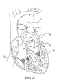
- Fig. 2 is a schematic sectional view of heart 26, showing insertion of catheter 24 into the heart, in accordance with an embodiment of the present invention.
- the operator first passes a sheath 40 percutaneously through the vascular system and into right atrium 44 of the heart through ascending vena cava 42.
- the sheath penetrates through interatrial septum 48, typically via the fossa ovalis, into left atrium 46.
- Catheter 24 is then inserted through the lumen of sheath 40 until an end section 52 of the catheter passes out of the distal opening at the end of the sheath into the left atrium, as shown in the figure.
- the end section is formed so as to define an arc when unconstrained, as is shown and described in greater detail hereinbelow with reference to Fig. 3 . While end section 52 is passing through sheath 40, however, the smaller inner diameter of the sheath holds the end section straight and roughly parallel to the catheter axis, as shown in Fig. 4 .
- Operator 22 aligns the longitudinal axis of sheath 40 (and of catheter 24) inside left atrium 46 with the axis of one of pulmonary veins 50.
- the operator may carry out this alignment using the position sensing methods described above, along with a pre-acquired map or image of heart 26. Alternatively or additionally, the alignment may be performed under fluoroscopic or other means of visualization.
- the operator advances end section 52 of the catheter toward the target pulmonary vein so that the arc contacts the ostium, and the end section either partly or fully surrounds the vein (depending on the angle subtended by the arc).
- the operator then rotates the catheter about its axis within the sheath so that the end section traces an annular path around the circumference of the vein. Meanwhile, the operator actuates RF generator 36 to ablate the tissue along the path. After completing this procedure around one pulmonary vein, the operator may shift the sheath and catheter and repeat the procedure around one or more of the other pulmonary veins.
- operator 22 may assess the extent and quality of the ablation by various means that are known in the art, such as ultrasonic sensing, magnetic resonance imaging (MRI), or measurement of local electrical properties of the tissue (such as impedance and/or activation voltage). If the operator discovers by such means (or in any other manner) that a certain point or points have not been sufficiently ablated, the operator may withdraw catheter 24 into sheath 40 until only the distal tip of end section 52 protrudes from the sheath. This sort of configuration is shown in Fig. 4 and is described in greater detail with reference thereto. In this latter configuration, the operator may advance the sheath and catheter so that only the distal tip of the catheter contacts the tissue at each point requiring further ablation. While the catheter contacts the tissue in this manner, the tip electrode of the catheter may be energized by RF generator 36 to ablate the tissue.
- Fig. 3 is a schematic side view of the distal portion of catheter 24, including end section 52 in its extended, arcuate configuration, in accordance with an embodiment of the present invention.
- the catheter comprises an insertion shaft 54, which connects at its distal end to the base of end section 52.
- Shaft 54 and end section 52 typically comprise an outer shell made from a suitable flexible biocompatible material, such as polyurethane, having a diameter around 2-3 mm, with internal wires and tubing as required.
- the size of the shaft is 7 Fr (about 2.3 mm diameter), while the end section is of the same or slightly larger size (such as 7.5 Fr).
- the shaft is 7 Fr, while the end section has a diameter between 1 and 2.5 mm.
- End section 52 is formed as a complete or partial lasso, i.e., as a preformed arcuate structure, which typically subtends between 180° and 360°.
- the radius of curvature of end section 52, when unconstrained, is typically between 7.5 mm and 15 mm. Because the arc structure is resilient and, possibly, slightly helical, when end section 52 is positioned in the heart (against the ostium of a pulmonary vein, for example), and insertion shaft 54 is advanced distally, the end section will press against the heart tissue over the entire length of the arc, thus facilitating good tissue contact.
- end section 52 may be maintained, for example, by incorporating a thin strut made from a shape memory material, such as Nitinol (not shown in the figures), in the desired shape within the end section.
- the strut is made sufficiently flexible to permit the end section to straighten during insertion and withdrawal through sheath 40, but to resume its arcuate form when it is unconstrained inside the heart chamber.
- End section 52 comprises an array of electrodes along its length, including, in this example, a tip electrode 60 extending over the distal tip of the end section and proximal electrodes 58 distributed along the end section.
- electrodes 58 have a width between 1 mm and 4 mm, and are spaced between 1 mm and 10 mm apart.
- Electrodes 58 and 60 are connected to the connector at the proximal end of catheter 24 by wires (not shown) running through the catheter.
- the end section may include smaller "bump" electrodes, as described in the above-mentioned U.S. Patent Application Publication 2010/0168548 .
- the electrodes may be used for sensing and/or ablation.
- catheter 24 may be rotated ("clocked") about its axis while applying RF electrical energy to the electrodes, as noted above.
- electrodes 58 and 60 may have perforations for irrigation.
- Perforations of this type are described and shown, for example, in U.S. Patent Application Publication 2010/0168548 .
- the perforations are coupled to one or more lumens in end section 52, which carries irrigation fluid from shaft 54 to the electrodes and to the tissue surrounding them. Details of an arrangement of electrodes and irrigation lumens that may be used for this purpose are described hereinbelow with reference to Fig. 5 .
- Catheter 24 may also include one or more position transducers, such as positions sensors 62, 64 and 66.
- sensors 62, 64 and 66 comprise coils, which output position signals in response to the magnetic fields of field generators 32 ( Fig. 1 ).
- sensor 66 may comprise three coils, which give full location and orientation information with regard to the base of end section 52, while sensors 62 and 64 each comprise a single coil, giving location and partial orientation information. This sort of arrangement is described further in the above-mentioned U.S. Patent Application Publication 2005/0033135 . It enables console 30 to track both the base location and the deformation of end section 52, so that the operator can verify that the end section is properly located and in good contact with the tissue. Alternatively, other types of position transducers and sensing configurations may be used in catheter 24 and system 20.
- Sheath 40 may also comprise one or more position transducers, as shown in Fig. 4 .
- Fig. 4 is a schematic side view of the distal end of catheter 24, showing end section 52 in its retracted, straightened configuration, in accordance with an embodiment of the present invention.
- Catheter 24 has been withdrawn into sheath 40 so that only tip electrode 60 protrudes distally, while proximal electrodes 58 are held inside the sheath.
- operator 22 may advance sheath 40 and catheter 24 together so that electrode 60 contacts particular points on the endocardium for purposes of electrical measurement and/or ablation.
- RF generator 36 applies energy only to tip electrode 60, and proximal electrodes 58 are not actuated.
- sheath 40 may contain one or more position transducers 70, as well.
- the position signals provided by transducer 70 in proximity to the distal opening of sheath 40 can be used for either or both of two purposes:
- other positioning elements may be used to sense the location of the distal tip of catheter 24 relative to sheath 40.
- a magnetic structure at the end of the sheath may be used for this purpose, as described in U.S. Patent Application 13/467,158 , whose disclosure is incorporated herein by reference.
- other sorts of transducers in the probe and/or sheath such as proximity sensors, may be used to ascertain the configuration of end section 52 relative to sheath 40.
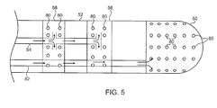
- Fig. 5 is a schematic side view of the distal tip of end section 52 of catheter 24, in accordance with an embodiment of the present invention.
- electrodes 58 and 60 have multiple perforations through which irrigation fluid may be delivered to tissue with which the catheter is in contact during ablation. Because tip electrode 60 may be actuated individually (in the configuration shown in Fig. 4 , for example), separately from ring electrodes 58, it is desirable that the tip electrode be irrigated separately from the ring electrodes.
- tip electrode 60 is served by a separate irrigation lumen 82, while ring electrodes 58 are served by a common irrigation lumen 84.
- console 30 supplies irrigation fluid to catheter 24 via both of lumens 82 and 84, so that all electrodes are irrigated.
- the console supplies irrigation fluid only to lumen 82.
- This sort of differential irrigation scheme may be applied, as well, to electrodes of other types (such as the bump electrodes shown in the above-mentioned U.S. Patent Application Publication 2010/0168548 ), and in substantially any other type of irrigated ablation probe in which multiple electrodes are actuated selectively.
Landscapes
- Health & Medical Sciences (AREA)
- Surgery (AREA)
- Engineering & Computer Science (AREA)
- Life Sciences & Earth Sciences (AREA)
- Biomedical Technology (AREA)
- Molecular Biology (AREA)
- Nuclear Medicine, Radiotherapy & Molecular Imaging (AREA)
- Plasma & Fusion (AREA)
- Physics & Mathematics (AREA)
- Heart & Thoracic Surgery (AREA)
- Medical Informatics (AREA)
- Otolaryngology (AREA)
- Animal Behavior & Ethology (AREA)
- General Health & Medical Sciences (AREA)
- Public Health (AREA)
- Veterinary Medicine (AREA)
- Cardiology (AREA)
- Surgical Instruments (AREA)
Applications Claiming Priority (1)
| Application Number | Priority Date | Filing Date | Title |
|---|---|---|---|
| US13/707,974 US9023036B2 (en) | 2012-12-07 | 2012-12-07 | Lasso catheter with tip electrode |
Publications (3)
| Publication Number | Publication Date |
|---|---|
| EP2740432A2 true EP2740432A2 (fr) | 2014-06-11 |
| EP2740432A3 EP2740432A3 (fr) | 2017-12-27 |
| EP2740432B1 EP2740432B1 (fr) | 2019-01-23 |
Family
ID=49753001
Family Applications (1)
| Application Number | Title | Priority Date | Filing Date |
|---|---|---|---|
| EP13196103.9A Active EP2740432B1 (fr) | 2012-12-07 | 2013-12-06 | Cathéter Lasso doté d' électrode à pointe |
Country Status (7)
| Country | Link |
|---|---|
| US (1) | US9023036B2 (fr) |
| EP (1) | EP2740432B1 (fr) |
| JP (1) | JP6333545B2 (fr) |
| CN (1) | CN103860264B (fr) |
| AU (2) | AU2013260655B2 (fr) |
| CA (1) | CA2835769C (fr) |
| IL (1) | IL229456A (fr) |
Cited By (3)
| Publication number | Priority date | Publication date | Assignee | Title |
|---|---|---|---|---|
| EP2977021A1 (fr) * | 2014-07-22 | 2016-01-27 | Biosense Webster (Israel) Ltd. | Catheter pourvu de multiples electrodes irriguees et un capteur de force |
| US9539056B2 (en) | 2012-03-20 | 2017-01-10 | Biosense Webster (Israel) Ltd. | Catheter with multiple irrigated electrodes and a force sensor |
| EP3381358A1 (fr) * | 2017-03-27 | 2018-10-03 | Biosense Webster (Israel) Ltd. | Capteur pour faciliter la visualisation d'un cathéter |
Families Citing this family (53)
| Publication number | Priority date | Publication date | Assignee | Title |
|---|---|---|---|---|
| JP6301926B2 (ja) | 2012-08-09 | 2018-03-28 | ユニバーシティ オブ アイオワ リサーチ ファウンデーション | カテーテル、カテーテルシステム、及び組織構造を刺通する方法 |
| US10098694B2 (en) | 2013-04-08 | 2018-10-16 | Apama Medical, Inc. | Tissue ablation and monitoring thereof |
| WO2015103574A1 (fr) | 2014-01-06 | 2015-07-09 | Iowa Approach Inc. | Appareil et procédés pour ablation de dénervation rénale |
| EP4670627A3 (fr) | 2014-05-07 | 2026-03-25 | Boston Scientific Scimed, Inc. | Procédés et appareil d'ablation sélective de tissu |
| WO2015175944A1 (fr) | 2014-05-16 | 2015-11-19 | Gary Long | Méthodes et appareil d'ablation tissulaire à plusieurs cathéters |
| WO2015192018A1 (fr) | 2014-06-12 | 2015-12-17 | Iowa Approach Inc. | Procédé et appareil d'ablation de tissu rapide et sélective à l'aide de refroidissement |
| EP3154463B1 (fr) | 2014-06-12 | 2019-03-27 | Farapulse, Inc. | Appareil d'ablation transurétrale de tissu rapide et sélective |
| HK1232111A1 (zh) * | 2014-06-24 | 2018-01-05 | Apama Medical, Inc. | 组织消融及其监测 |
| EP3206613B1 (fr) | 2014-10-14 | 2019-07-03 | Farapulse, Inc. | Appareil pour l'ablation rapide et sûre d'une veine cardiopulmonaire |
| US11013554B2 (en) * | 2014-11-14 | 2021-05-25 | Medtronic Ardian Lexembourg S.A.R.L. | Catheter apparatuses for modulation of nerves in communication with pulmonary system and associated systems and methods |
| EP3307188A4 (fr) * | 2015-06-10 | 2019-01-23 | CathRx Ltd | Cathéter à double forme |
| US10130423B1 (en) | 2017-07-06 | 2018-11-20 | Farapulse, Inc. | Systems, devices, and methods for focal ablation |
| US12144541B2 (en) | 2016-01-05 | 2024-11-19 | Boston Scientific Scimed, Inc. | Systems, apparatuses and methods for delivery of ablative energy to tissue |
| US10660702B2 (en) | 2016-01-05 | 2020-05-26 | Farapulse, Inc. | Systems, devices, and methods for focal ablation |
| US20170189097A1 (en) | 2016-01-05 | 2017-07-06 | Iowa Approach Inc. | Systems, apparatuses and methods for delivery of ablative energy to tissue |
| US10172673B2 (en) | 2016-01-05 | 2019-01-08 | Farapulse, Inc. | Systems devices, and methods for delivery of pulsed electric field ablative energy to endocardial tissue |
| US10905329B2 (en) | 2016-06-09 | 2021-02-02 | Biosense Webster (Israel) Ltd. | Multi-function conducting elements for a catheter |
| EP3471631A4 (fr) | 2016-06-16 | 2020-03-04 | Farapulse, Inc. | Systèmes, appareils et procédés de distribution de fil de guidage |
| US10702177B2 (en) * | 2016-08-24 | 2020-07-07 | Biosense Webster (Israel) Ltd. | Catheter with bipole electrode spacer and related methods |
| US10898262B2 (en) | 2016-10-25 | 2021-01-26 | Biosense Webster (Israel) Ltd. | Catheter distal end made of plastic tube and flexible printed circuit boards |
| US10849677B2 (en) * | 2017-01-27 | 2020-12-01 | Medtronic, Inc. | Methods of ensuring pulsed field ablation generator system electrical safety |
| US9987081B1 (en) | 2017-04-27 | 2018-06-05 | Iowa Approach, Inc. | Systems, devices, and methods for signal generation |
| US10617867B2 (en) | 2017-04-28 | 2020-04-14 | Farapulse, Inc. | Systems, devices, and methods for delivery of pulsed electric field ablative energy to esophageal tissue |
| CN115844523A (zh) | 2017-09-12 | 2023-03-28 | 波士顿科学医学有限公司 | 用于心室局灶性消融的系统、设备和方法 |
| EP3461526A1 (fr) * | 2017-09-28 | 2019-04-03 | Koninklijke Philips N.V. | Dispositif médical invasif et procédé de fabrication |
| US10893902B2 (en) * | 2017-10-25 | 2021-01-19 | Biosense Webster (Israel) Ltd. | Integrated resistive filters in catheter distal end |
| US12458435B2 (en) * | 2018-01-24 | 2025-11-04 | Medtronic Ireland Manufacturing Unlimited Company | Multielectrode catheter |
| EP3749238B1 (fr) | 2018-02-08 | 2023-08-16 | Farapulse, Inc. | Appareil d'application contrôlée d'une énergie d'ablation à champ électrique pulsé sur un tissu |
| US11864825B2 (en) * | 2018-05-02 | 2024-01-09 | Biosense Webster (Israel) Ltd. | Ablation catheter with selective radial energy delivery |
| US20190336198A1 (en) | 2018-05-03 | 2019-11-07 | Farapulse, Inc. | Systems, devices, and methods for ablation using surgical clamps |
| CN116327352A (zh) | 2018-05-07 | 2023-06-27 | 波士顿科学医学有限公司 | 心外膜消融导管 |
| CN115836908A (zh) | 2018-05-07 | 2023-03-24 | 波士顿科学医学有限公司 | 用于将消融能量递送到组织的系统、设备和方法 |
| EP3790483B1 (fr) | 2018-05-07 | 2024-08-28 | Boston Scientific Scimed, Inc. | Systèmes pour filtrer un bruit haute tension induit par une ablation par champ électrique pulsé |
| CN112955088B (zh) | 2018-09-20 | 2024-11-26 | 波士顿科学医学有限公司 | 用于将脉冲电场消融能量输送到心内膜组织的系统、装置和方法 |
| US11648053B2 (en) * | 2018-12-20 | 2023-05-16 | Biosense Webster (Israel) Ltd. | Catheter with flex circuit distal assembly |
| EP3962356B1 (fr) * | 2019-05-02 | 2023-05-24 | Intersect ENT International GmbH | Support de capteur |
| EP3965678B1 (fr) | 2019-05-06 | 2023-12-20 | Boston Scientific Scimed, Inc. | Dispositif médical |
| US20200397505A1 (en) * | 2019-06-19 | 2020-12-24 | Farapulse, Inc. | Systems, devices, and methods for focal ablation |
| US10625080B1 (en) | 2019-09-17 | 2020-04-21 | Farapulse, Inc. | Systems, apparatuses, and methods for detecting ectopic electrocardiogram signals during pulsed electric field ablation |
| US12114920B2 (en) * | 2019-10-22 | 2024-10-15 | Biosense Webster (Israel) Ltd. | Inflatable sleeve multi-electrode catheter |
| US11065047B2 (en) | 2019-11-20 | 2021-07-20 | Farapulse, Inc. | Systems, apparatuses, and methods for protecting electronic components from high power noise induced by high voltage pulses |
| US11497541B2 (en) | 2019-11-20 | 2022-11-15 | Boston Scientific Scimed, Inc. | Systems, apparatuses, and methods for protecting electronic components from high power noise induced by high voltage pulses |
| US10842572B1 (en) | 2019-11-25 | 2020-11-24 | Farapulse, Inc. | Methods, systems, and apparatuses for tracking ablation devices and generating lesion lines |
| JP2023535080A (ja) * | 2020-07-24 | 2023-08-15 | ボストン サイエンティフィック サイムド,インコーポレイテッド | 電気穿孔法アブレーションカテーテル |
| JP7536995B2 (ja) | 2020-07-24 | 2024-08-20 | ボストン サイエンティフィック サイムド,インコーポレイテッド | 不可逆電気穿孔によるシングル・ショット心臓アブレーションのための電界印加 |
| US12310652B2 (en) | 2020-07-24 | 2025-05-27 | Boston Scientific Scimed, Inc. | Hybrid electroporation ablation catheter |
| US12016612B2 (en) * | 2020-08-19 | 2024-06-25 | Acclarent, Inc. | ENT ablation instrument with electrode loop |
| US12496123B2 (en) | 2020-09-08 | 2025-12-16 | Boston Scientific Scimed, Inc. | Contoured electrodes for pulsed electric field ablation, and systems, devices, and methods thereof |
| WO2022072385A2 (fr) | 2020-09-30 | 2022-04-07 | Boston Scientific Scimed Inc | Forme d'onde de traitement préalable d'électroporation irréversible |
| EP4284276A1 (fr) | 2021-01-27 | 2023-12-06 | Boston Scientific Scimed, Inc. | Séquences d'impulsions commandées par tension pour ablations irréversibles par électroporation |
| WO2022204719A1 (fr) * | 2021-03-26 | 2022-09-29 | DIXI Neurolab, Inc. | Appareil à double ballonnet pour le traitement de la névralgie du trijumeau |
| CN117653323A (zh) * | 2022-08-31 | 2024-03-08 | 杭州诺沁医疗器械有限公司 | 引导组件、消融装置及消融系统 |
| US12484963B2 (en) | 2024-04-03 | 2025-12-02 | Field Medical, Inc. | Systems and methods for affecting a target tissue via a pulsed field |
Citations (5)
| Publication number | Priority date | Publication date | Assignee | Title |
|---|---|---|---|---|
| WO1996005768A1 (fr) | 1994-08-19 | 1996-02-29 | Biosense, Inc. | Systemes medicaux de diagnostic, de traitement et d'imagerie |
| US6064902A (en) | 1998-04-16 | 2000-05-16 | C.R. Bard, Inc. | Pulmonary vein ablation catheter |
| US20050033135A1 (en) | 2003-07-29 | 2005-02-10 | Assaf Govari | Lasso for pulmonary vein mapping and ablation |
| US20100168548A1 (en) | 2008-12-30 | 2010-07-01 | Assaf Govari | Dual-Purpose Lasso Catheter with Irrigation |
| US20110160719A1 (en) | 2009-12-30 | 2011-06-30 | Assaf Govari | Catheter with arcuate end section |
Family Cites Families (7)
| Publication number | Priority date | Publication date | Assignee | Title |
|---|---|---|---|---|
| US6210406B1 (en) * | 1998-12-03 | 2001-04-03 | Cordis Webster, Inc. | Split tip electrode catheter and signal processing RF ablation system |
| WO2002054941A2 (fr) * | 2001-01-11 | 2002-07-18 | Rita Medical Systems Inc | Instrument et procede de traitement de l'os |
| US6671533B2 (en) * | 2001-10-11 | 2003-12-30 | Irvine Biomedical Inc. | System and method for mapping and ablating body tissue of the interior region of the heart |
| US8517999B2 (en) * | 2007-04-04 | 2013-08-27 | St. Jude Medical, Atrial Fibrillation Division, Inc. | Irrigated catheter with improved fluid flow |
| US8845630B2 (en) * | 2007-06-15 | 2014-09-30 | Syneron Medical Ltd | Devices and methods for percutaneous energy delivery |
| US9616199B2 (en) * | 2009-12-31 | 2017-04-11 | St. Jude Medical, Atrial Fibrillation Division, Inc. | Irrigated catheter employing multi-lumenal irrigation tubing |
| US9662169B2 (en) * | 2011-07-30 | 2017-05-30 | Biosense Webster (Israel) Ltd. | Catheter with flow balancing valve |
-
2012
- 2012-12-07 US US13/707,974 patent/US9023036B2/en active Active
-
2013
- 2013-11-14 IL IL229456A patent/IL229456A/en active IP Right Grant
- 2013-11-20 AU AU2013260655A patent/AU2013260655B2/en not_active Ceased
- 2013-12-03 CA CA2835769A patent/CA2835769C/fr active Active
- 2013-12-06 CN CN201310655973.4A patent/CN103860264B/zh active Active
- 2013-12-06 JP JP2013252917A patent/JP6333545B2/ja active Active
- 2013-12-06 EP EP13196103.9A patent/EP2740432B1/fr active Active
-
2018
- 2018-06-14 AU AU2018204229A patent/AU2018204229B2/en not_active Ceased
Patent Citations (5)
| Publication number | Priority date | Publication date | Assignee | Title |
|---|---|---|---|---|
| WO1996005768A1 (fr) | 1994-08-19 | 1996-02-29 | Biosense, Inc. | Systemes medicaux de diagnostic, de traitement et d'imagerie |
| US6064902A (en) | 1998-04-16 | 2000-05-16 | C.R. Bard, Inc. | Pulmonary vein ablation catheter |
| US20050033135A1 (en) | 2003-07-29 | 2005-02-10 | Assaf Govari | Lasso for pulmonary vein mapping and ablation |
| US20100168548A1 (en) | 2008-12-30 | 2010-07-01 | Assaf Govari | Dual-Purpose Lasso Catheter with Irrigation |
| US20110160719A1 (en) | 2009-12-30 | 2011-06-30 | Assaf Govari | Catheter with arcuate end section |
Cited By (7)
| Publication number | Priority date | Publication date | Assignee | Title |
|---|---|---|---|---|
| US9539056B2 (en) | 2012-03-20 | 2017-01-10 | Biosense Webster (Israel) Ltd. | Catheter with multiple irrigated electrodes and a force sensor |
| EP2977021A1 (fr) * | 2014-07-22 | 2016-01-27 | Biosense Webster (Israel) Ltd. | Catheter pourvu de multiples electrodes irriguees et un capteur de force |
| CN105286987A (zh) * | 2014-07-22 | 2016-02-03 | 韦伯斯特生物官能(以色列)有限公司 | 具有多个冲洗电极和力传感器的导管 |
| CN105286987B (zh) * | 2014-07-22 | 2020-04-10 | 韦伯斯特生物官能(以色列)有限公司 | 具有多个冲洗电极和力传感器的导管 |
| EP3381358A1 (fr) * | 2017-03-27 | 2018-10-03 | Biosense Webster (Israel) Ltd. | Capteur pour faciliter la visualisation d'un cathéter |
| CN108714270A (zh) * | 2017-03-27 | 2018-10-30 | 韦伯斯特生物官能(以色列)有限公司 | 用于促进导管可视化的传感器 |
| US10959643B2 (en) | 2017-03-27 | 2021-03-30 | Biosense Webster (Israel) Ltd. | Sensor for facilitating catheter visualization |
Also Published As
| Publication number | Publication date |
|---|---|
| JP6333545B2 (ja) | 2018-05-30 |
| JP2014113493A (ja) | 2014-06-26 |
| AU2018204229B2 (en) | 2020-01-30 |
| IL229456A (en) | 2017-05-29 |
| CA2835769C (fr) | 2022-12-06 |
| CA2835769A1 (fr) | 2014-06-07 |
| EP2740432A3 (fr) | 2017-12-27 |
| AU2013260655A1 (en) | 2014-06-26 |
| US20140163546A1 (en) | 2014-06-12 |
| US9023036B2 (en) | 2015-05-05 |
| CN103860264A (zh) | 2014-06-18 |
| AU2013260655B2 (en) | 2018-07-12 |
| AU2018204229A1 (en) | 2018-09-06 |
| CN103860264B (zh) | 2020-02-21 |
| EP2740432B1 (fr) | 2019-01-23 |
Similar Documents
| Publication | Publication Date | Title |
|---|---|---|
| AU2018204229B2 (en) | Lasso catheter with tip electrode | |
| EP2340765B1 (fr) | Cathéter doté d'une section à extrémité arquée | |
| US8926589B2 (en) | Pre-formed curved ablation catheter | |
| CN102090924B (zh) | 预成形的弯曲消融导管 |
Legal Events
| Date | Code | Title | Description |
|---|---|---|---|
| PUAI | Public reference made under article 153(3) epc to a published international application that has entered the european phase |
Free format text: ORIGINAL CODE: 0009012 |
|
| 17P | Request for examination filed |
Effective date: 20131206 |
|
| AK | Designated contracting states |
Kind code of ref document: A2 Designated state(s): AL AT BE BG CH CY CZ DE DK EE ES FI FR GB GR HR HU IE IS IT LI LT LU LV MC MK MT NL NO PL PT RO RS SE SI SK SM TR |
|
| AX | Request for extension of the european patent |
Extension state: BA ME |
|
| RIC1 | Information provided on ipc code assigned before grant |
Ipc: A61B 18/14 20060101AFI20170728BHEP |
|
| PUAL | Search report despatched |
Free format text: ORIGINAL CODE: 0009013 |
|
| RIC1 | Information provided on ipc code assigned before grant |
Ipc: A61B 19/00 00000000ALN20171114BHEP Ipc: A61B 18/14 20060101AFI20171114BHEP Ipc: A61B 18/12 20060101ALN20171114BHEP |
|
| AK | Designated contracting states |
Kind code of ref document: A3 Designated state(s): AL AT BE BG CH CY CZ DE DK EE ES FI FR GB GR HR HU IE IS IT LI LT LU LV MC MK MT NL NO PL PT RO RS SE SI SK SM TR |
|
| AX | Request for extension of the european patent |
Extension state: BA ME |
|
| RIC1 | Information provided on ipc code assigned before grant |
Ipc: A61B 18/12 20060101ALN20171117BHEP Ipc: A61B 19/00 00000000ALN20171117BHEP Ipc: A61B 18/14 20060101AFI20171117BHEP |
|
| STAA | Information on the status of an ep patent application or granted ep patent |
Free format text: STATUS: REQUEST FOR EXAMINATION WAS MADE |
|
| R17P | Request for examination filed (corrected) |
Effective date: 20180308 |
|
| RBV | Designated contracting states (corrected) |
Designated state(s): AL AT BE BG CH CY CZ DE DK EE ES FI FR GB GR HR HU IE IS IT LI LT LU LV MC MK MT NL NO PL PT RO RS SE SI SK SM TR |
|
| GRAP | Despatch of communication of intention to grant a patent |
Free format text: ORIGINAL CODE: EPIDOSNIGR1 |
|
| STAA | Information on the status of an ep patent application or granted ep patent |
Free format text: STATUS: GRANT OF PATENT IS INTENDED |
|
| RIC1 | Information provided on ipc code assigned before grant |
Ipc: A61B 18/12 20060101ALN20180523BHEP Ipc: A61B 18/14 20060101AFI20180523BHEP Ipc: A61B 34/20 20160101ALN20180523BHEP |
|
| INTG | Intention to grant announced |
Effective date: 20180613 |
|
| GRAS | Grant fee paid |
Free format text: ORIGINAL CODE: EPIDOSNIGR3 |
|
| GRAA | (expected) grant |
Free format text: ORIGINAL CODE: 0009210 |
|
| STAA | Information on the status of an ep patent application or granted ep patent |
Free format text: STATUS: THE PATENT HAS BEEN GRANTED |
|
| RAP1 | Party data changed (applicant data changed or rights of an application transferred) |
Owner name: BIOSENSE WEBSTER (ISRAEL) LTD. |
|
| AK | Designated contracting states |
Kind code of ref document: B1 Designated state(s): AL AT BE BG CH CY CZ DE DK EE ES FI FR GB GR HR HU IE IS IT LI LT LU LV MC MK MT NL NO PL PT RO RS SE SI SK SM TR |
|
| REG | Reference to a national code |
Ref country code: GB Ref legal event code: FG4D |
|
| REG | Reference to a national code |
Ref country code: CH Ref legal event code: EP |
|
| RIC2 | Information provided on ipc code assigned after grant |
Ipc: A61B 34/20 20160101ALN20180523BHEP Ipc: A61B 18/12 20060101ALN20180523BHEP Ipc: A61B 18/14 20060101AFI20180523BHEP |
|
| REG | Reference to a national code |
Ref country code: AT Ref legal event code: REF Ref document number: 1090855 Country of ref document: AT Kind code of ref document: T Effective date: 20190215 |
|
| REG | Reference to a national code |
Ref country code: IE Ref legal event code: FG4D |
|
| REG | Reference to a national code |
Ref country code: DE Ref legal event code: R096 Ref document number: 602013050161 Country of ref document: DE |
|
| REG | Reference to a national code |
Ref country code: NL Ref legal event code: MP Effective date: 20190123 |
|
| PG25 | Lapsed in a contracting state [announced via postgrant information from national office to epo] |
Ref country code: NL Free format text: LAPSE BECAUSE OF FAILURE TO SUBMIT A TRANSLATION OF THE DESCRIPTION OR TO PAY THE FEE WITHIN THE PRESCRIBED TIME-LIMIT Effective date: 20190123 |
|
| PG25 | Lapsed in a contracting state [announced via postgrant information from national office to epo] |
Ref country code: PT Free format text: LAPSE BECAUSE OF FAILURE TO SUBMIT A TRANSLATION OF THE DESCRIPTION OR TO PAY THE FEE WITHIN THE PRESCRIBED TIME-LIMIT Effective date: 20190523 Ref country code: SE Free format text: LAPSE BECAUSE OF FAILURE TO SUBMIT A TRANSLATION OF THE DESCRIPTION OR TO PAY THE FEE WITHIN THE PRESCRIBED TIME-LIMIT Effective date: 20190123 Ref country code: NO Free format text: LAPSE BECAUSE OF FAILURE TO SUBMIT A TRANSLATION OF THE DESCRIPTION OR TO PAY THE FEE WITHIN THE PRESCRIBED TIME-LIMIT Effective date: 20190423 Ref country code: FI Free format text: LAPSE BECAUSE OF FAILURE TO SUBMIT A TRANSLATION OF THE DESCRIPTION OR TO PAY THE FEE WITHIN THE PRESCRIBED TIME-LIMIT Effective date: 20190123 Ref country code: PL Free format text: LAPSE BECAUSE OF FAILURE TO SUBMIT A TRANSLATION OF THE DESCRIPTION OR TO PAY THE FEE WITHIN THE PRESCRIBED TIME-LIMIT Effective date: 20190123 Ref country code: LT Free format text: LAPSE BECAUSE OF FAILURE TO SUBMIT A TRANSLATION OF THE DESCRIPTION OR TO PAY THE FEE WITHIN THE PRESCRIBED TIME-LIMIT Effective date: 20190123 Ref country code: ES Free format text: LAPSE BECAUSE OF FAILURE TO SUBMIT A TRANSLATION OF THE DESCRIPTION OR TO PAY THE FEE WITHIN THE PRESCRIBED TIME-LIMIT Effective date: 20190123 |
|
| REG | Reference to a national code |
Ref country code: AT Ref legal event code: MK05 Ref document number: 1090855 Country of ref document: AT Kind code of ref document: T Effective date: 20190123 |
|
| PG25 | Lapsed in a contracting state [announced via postgrant information from national office to epo] |
Ref country code: IS Free format text: LAPSE BECAUSE OF FAILURE TO SUBMIT A TRANSLATION OF THE DESCRIPTION OR TO PAY THE FEE WITHIN THE PRESCRIBED TIME-LIMIT Effective date: 20190523 Ref country code: LV Free format text: LAPSE BECAUSE OF FAILURE TO SUBMIT A TRANSLATION OF THE DESCRIPTION OR TO PAY THE FEE WITHIN THE PRESCRIBED TIME-LIMIT Effective date: 20190123 Ref country code: BG Free format text: LAPSE BECAUSE OF FAILURE TO SUBMIT A TRANSLATION OF THE DESCRIPTION OR TO PAY THE FEE WITHIN THE PRESCRIBED TIME-LIMIT Effective date: 20190423 Ref country code: HR Free format text: LAPSE BECAUSE OF FAILURE TO SUBMIT A TRANSLATION OF THE DESCRIPTION OR TO PAY THE FEE WITHIN THE PRESCRIBED TIME-LIMIT Effective date: 20190123 Ref country code: GR Free format text: LAPSE BECAUSE OF FAILURE TO SUBMIT A TRANSLATION OF THE DESCRIPTION OR TO PAY THE FEE WITHIN THE PRESCRIBED TIME-LIMIT Effective date: 20190424 Ref country code: RS Free format text: LAPSE BECAUSE OF FAILURE TO SUBMIT A TRANSLATION OF THE DESCRIPTION OR TO PAY THE FEE WITHIN THE PRESCRIBED TIME-LIMIT Effective date: 20190123 |
|
| REG | Reference to a national code |
Ref country code: DE Ref legal event code: R097 Ref document number: 602013050161 Country of ref document: DE |
|
| PG25 | Lapsed in a contracting state [announced via postgrant information from national office to epo] |
Ref country code: EE Free format text: LAPSE BECAUSE OF FAILURE TO SUBMIT A TRANSLATION OF THE DESCRIPTION OR TO PAY THE FEE WITHIN THE PRESCRIBED TIME-LIMIT Effective date: 20190123 Ref country code: DK Free format text: LAPSE BECAUSE OF FAILURE TO SUBMIT A TRANSLATION OF THE DESCRIPTION OR TO PAY THE FEE WITHIN THE PRESCRIBED TIME-LIMIT Effective date: 20190123 Ref country code: AL Free format text: LAPSE BECAUSE OF FAILURE TO SUBMIT A TRANSLATION OF THE DESCRIPTION OR TO PAY THE FEE WITHIN THE PRESCRIBED TIME-LIMIT Effective date: 20190123 Ref country code: CZ Free format text: LAPSE BECAUSE OF FAILURE TO SUBMIT A TRANSLATION OF THE DESCRIPTION OR TO PAY THE FEE WITHIN THE PRESCRIBED TIME-LIMIT Effective date: 20190123 Ref country code: RO Free format text: LAPSE BECAUSE OF FAILURE TO SUBMIT A TRANSLATION OF THE DESCRIPTION OR TO PAY THE FEE WITHIN THE PRESCRIBED TIME-LIMIT Effective date: 20190123 Ref country code: SK Free format text: LAPSE BECAUSE OF FAILURE TO SUBMIT A TRANSLATION OF THE DESCRIPTION OR TO PAY THE FEE WITHIN THE PRESCRIBED TIME-LIMIT Effective date: 20190123 |
|
| PG25 | Lapsed in a contracting state [announced via postgrant information from national office to epo] |
Ref country code: SM Free format text: LAPSE BECAUSE OF FAILURE TO SUBMIT A TRANSLATION OF THE DESCRIPTION OR TO PAY THE FEE WITHIN THE PRESCRIBED TIME-LIMIT Effective date: 20190123 |
|
| PLBE | No opposition filed within time limit |
Free format text: ORIGINAL CODE: 0009261 |
|
| STAA | Information on the status of an ep patent application or granted ep patent |
Free format text: STATUS: NO OPPOSITION FILED WITHIN TIME LIMIT |
|
| PG25 | Lapsed in a contracting state [announced via postgrant information from national office to epo] |
Ref country code: AT Free format text: LAPSE BECAUSE OF FAILURE TO SUBMIT A TRANSLATION OF THE DESCRIPTION OR TO PAY THE FEE WITHIN THE PRESCRIBED TIME-LIMIT Effective date: 20190123 |
|
| 26N | No opposition filed |
Effective date: 20191024 |
|
| PG25 | Lapsed in a contracting state [announced via postgrant information from national office to epo] |
Ref country code: SI Free format text: LAPSE BECAUSE OF FAILURE TO SUBMIT A TRANSLATION OF THE DESCRIPTION OR TO PAY THE FEE WITHIN THE PRESCRIBED TIME-LIMIT Effective date: 20190123 |
|
| PGFP | Annual fee paid to national office [announced via postgrant information from national office to epo] |
Ref country code: BE Payment date: 20191118 Year of fee payment: 7 |
|
| PG25 | Lapsed in a contracting state [announced via postgrant information from national office to epo] |
Ref country code: TR Free format text: LAPSE BECAUSE OF FAILURE TO SUBMIT A TRANSLATION OF THE DESCRIPTION OR TO PAY THE FEE WITHIN THE PRESCRIBED TIME-LIMIT Effective date: 20190123 |
|
| PG25 | Lapsed in a contracting state [announced via postgrant information from national office to epo] |
Ref country code: MC Free format text: LAPSE BECAUSE OF FAILURE TO SUBMIT A TRANSLATION OF THE DESCRIPTION OR TO PAY THE FEE WITHIN THE PRESCRIBED TIME-LIMIT Effective date: 20190123 |
|
| PG25 | Lapsed in a contracting state [announced via postgrant information from national office to epo] |
Ref country code: LU Free format text: LAPSE BECAUSE OF NON-PAYMENT OF DUE FEES Effective date: 20191206 Ref country code: IE Free format text: LAPSE BECAUSE OF NON-PAYMENT OF DUE FEES Effective date: 20191206 |
|
| PG25 | Lapsed in a contracting state [announced via postgrant information from national office to epo] |
Ref country code: CY Free format text: LAPSE BECAUSE OF FAILURE TO SUBMIT A TRANSLATION OF THE DESCRIPTION OR TO PAY THE FEE WITHIN THE PRESCRIBED TIME-LIMIT Effective date: 20190123 |
|
| PG25 | Lapsed in a contracting state [announced via postgrant information from national office to epo] |
Ref country code: MT Free format text: LAPSE BECAUSE OF FAILURE TO SUBMIT A TRANSLATION OF THE DESCRIPTION OR TO PAY THE FEE WITHIN THE PRESCRIBED TIME-LIMIT Effective date: 20190123 Ref country code: HU Free format text: LAPSE BECAUSE OF FAILURE TO SUBMIT A TRANSLATION OF THE DESCRIPTION OR TO PAY THE FEE WITHIN THE PRESCRIBED TIME-LIMIT; INVALID AB INITIO Effective date: 20131206 |
|
| REG | Reference to a national code |
Ref country code: BE Ref legal event code: MM Effective date: 20201231 |
|
| PG25 | Lapsed in a contracting state [announced via postgrant information from national office to epo] |
Ref country code: MK Free format text: LAPSE BECAUSE OF FAILURE TO SUBMIT A TRANSLATION OF THE DESCRIPTION OR TO PAY THE FEE WITHIN THE PRESCRIBED TIME-LIMIT Effective date: 20190123 |
|
| PG25 | Lapsed in a contracting state [announced via postgrant information from national office to epo] |
Ref country code: BE Free format text: LAPSE BECAUSE OF NON-PAYMENT OF DUE FEES Effective date: 20201231 |
|
| PGFP | Annual fee paid to national office [announced via postgrant information from national office to epo] |
Ref country code: CH Payment date: 20230101 Year of fee payment: 10 |
|
| REG | Reference to a national code |
Ref country code: CH Ref legal event code: PL |
|
| PG25 | Lapsed in a contracting state [announced via postgrant information from national office to epo] |
Ref country code: CH Free format text: LAPSE BECAUSE OF NON-PAYMENT OF DUE FEES Effective date: 20231231 |
|
| PG25 | Lapsed in a contracting state [announced via postgrant information from national office to epo] |
Ref country code: CH Free format text: LAPSE BECAUSE OF NON-PAYMENT OF DUE FEES Effective date: 20231231 |
|
| PGFP | Annual fee paid to national office [announced via postgrant information from national office to epo] |
Ref country code: DE Payment date: 20251028 Year of fee payment: 13 |
|
| PGFP | Annual fee paid to national office [announced via postgrant information from national office to epo] |
Ref country code: GB Payment date: 20251030 Year of fee payment: 13 |
|
| PGFP | Annual fee paid to national office [announced via postgrant information from national office to epo] |
Ref country code: IT Payment date: 20251121 Year of fee payment: 13 |
|
| PGFP | Annual fee paid to national office [announced via postgrant information from national office to epo] |
Ref country code: FR Payment date: 20251110 Year of fee payment: 13 |