EP2740457A2 - Vorrichtung für kontinuierliche passive bewegung - Google Patents
Vorrichtung für kontinuierliche passive bewegung Download PDFInfo
- Publication number
- EP2740457A2 EP2740457A2 EP12780217.1A EP12780217A EP2740457A2 EP 2740457 A2 EP2740457 A2 EP 2740457A2 EP 12780217 A EP12780217 A EP 12780217A EP 2740457 A2 EP2740457 A2 EP 2740457A2
- Authority
- EP
- European Patent Office
- Prior art keywords
- inducing
- flexion
- support
- joint
- motion device
- Prior art date
- Legal status (The legal status is an assumption and is not a legal conclusion. Google has not performed a legal analysis and makes no representation as to the accuracy of the status listed.)
- Withdrawn
Links
Images


Classifications
-
- A—HUMAN NECESSITIES
- A61—MEDICAL OR VETERINARY SCIENCE; HYGIENE
- A61H—PHYSICAL THERAPY APPARATUS, e.g. DEVICES FOR LOCATING OR STIMULATING REFLEX POINTS IN THE BODY; ARTIFICIAL RESPIRATION; MASSAGE; BATHING DEVICES FOR SPECIAL THERAPEUTIC OR HYGIENIC PURPOSES OR SPECIFIC PARTS OF THE BODY
- A61H1/00—Apparatus for passive exercising; Vibrating apparatus; Chiropractic devices, e.g. body impacting devices, external devices for briefly extending or aligning unbroken bones
- A61H1/02—Stretching or bending or torsioning apparatus for exercising
- A61H1/0237—Stretching or bending or torsioning apparatus for exercising for the lower limbs
- A61H1/0255—Both knee and hip of a patient, e.g. in supine or sitting position, the feet being moved together in a plane substantially parallel to the body-symmetrical plane
- A61H1/0259—Both knee and hip of a patient, e.g. in supine or sitting position, the feet being moved together in a plane substantially parallel to the body-symmetrical plane moved by translation
-
- A—HUMAN NECESSITIES
- A61—MEDICAL OR VETERINARY SCIENCE; HYGIENE
- A61H—PHYSICAL THERAPY APPARATUS, e.g. DEVICES FOR LOCATING OR STIMULATING REFLEX POINTS IN THE BODY; ARTIFICIAL RESPIRATION; MASSAGE; BATHING DEVICES FOR SPECIAL THERAPEUTIC OR HYGIENIC PURPOSES OR SPECIFIC PARTS OF THE BODY
- A61H1/00—Apparatus for passive exercising; Vibrating apparatus; Chiropractic devices, e.g. body impacting devices, external devices for briefly extending or aligning unbroken bones
- A61H1/02—Stretching or bending or torsioning apparatus for exercising
- A61H1/0237—Stretching or bending or torsioning apparatus for exercising for the lower limbs
- A61H1/024—Knee
-
- A—HUMAN NECESSITIES
- A61—MEDICAL OR VETERINARY SCIENCE; HYGIENE
- A61H—PHYSICAL THERAPY APPARATUS, e.g. DEVICES FOR LOCATING OR STIMULATING REFLEX POINTS IN THE BODY; ARTIFICIAL RESPIRATION; MASSAGE; BATHING DEVICES FOR SPECIAL THERAPEUTIC OR HYGIENIC PURPOSES OR SPECIFIC PARTS OF THE BODY
- A61H2201/00—Characteristics of apparatus not provided for in the preceding codes
- A61H2201/12—Driving means
- A61H2201/1207—Driving means with electric or magnetic drive
- A61H2201/1215—Rotary drive
-
- A—HUMAN NECESSITIES
- A61—MEDICAL OR VETERINARY SCIENCE; HYGIENE
- A61H—PHYSICAL THERAPY APPARATUS, e.g. DEVICES FOR LOCATING OR STIMULATING REFLEX POINTS IN THE BODY; ARTIFICIAL RESPIRATION; MASSAGE; BATHING DEVICES FOR SPECIAL THERAPEUTIC OR HYGIENIC PURPOSES OR SPECIFIC PARTS OF THE BODY
- A61H2201/00—Characteristics of apparatus not provided for in the preceding codes
- A61H2201/12—Driving means
- A61H2201/1207—Driving means with electric or magnetic drive
- A61H2201/123—Linear drive
-
- A—HUMAN NECESSITIES
- A61—MEDICAL OR VETERINARY SCIENCE; HYGIENE
- A61H—PHYSICAL THERAPY APPARATUS, e.g. DEVICES FOR LOCATING OR STIMULATING REFLEX POINTS IN THE BODY; ARTIFICIAL RESPIRATION; MASSAGE; BATHING DEVICES FOR SPECIAL THERAPEUTIC OR HYGIENIC PURPOSES OR SPECIFIC PARTS OF THE BODY
- A61H2201/00—Characteristics of apparatus not provided for in the preceding codes
- A61H2201/12—Driving means
- A61H2201/1238—Driving means with hydraulic or pneumatic drive
- A61H2201/1246—Driving means with hydraulic or pneumatic drive by piston-cylinder systems
-
- A—HUMAN NECESSITIES
- A61—MEDICAL OR VETERINARY SCIENCE; HYGIENE
- A61H—PHYSICAL THERAPY APPARATUS, e.g. DEVICES FOR LOCATING OR STIMULATING REFLEX POINTS IN THE BODY; ARTIFICIAL RESPIRATION; MASSAGE; BATHING DEVICES FOR SPECIAL THERAPEUTIC OR HYGIENIC PURPOSES OR SPECIFIC PARTS OF THE BODY
- A61H2201/00—Characteristics of apparatus not provided for in the preceding codes
- A61H2201/14—Special force transmission means, i.e. between the driving means and the interface with the user
- A61H2201/1409—Hydraulic or pneumatic means
-
- A—HUMAN NECESSITIES
- A61—MEDICAL OR VETERINARY SCIENCE; HYGIENE
- A61H—PHYSICAL THERAPY APPARATUS, e.g. DEVICES FOR LOCATING OR STIMULATING REFLEX POINTS IN THE BODY; ARTIFICIAL RESPIRATION; MASSAGE; BATHING DEVICES FOR SPECIAL THERAPEUTIC OR HYGIENIC PURPOSES OR SPECIFIC PARTS OF THE BODY
- A61H2201/00—Characteristics of apparatus not provided for in the preceding codes
- A61H2201/14—Special force transmission means, i.e. between the driving means and the interface with the user
- A61H2201/1481—Special movement conversion means
- A61H2201/149—Special movement conversion means rotation-linear or vice versa
-
- A—HUMAN NECESSITIES
- A61—MEDICAL OR VETERINARY SCIENCE; HYGIENE
- A61H—PHYSICAL THERAPY APPARATUS, e.g. DEVICES FOR LOCATING OR STIMULATING REFLEX POINTS IN THE BODY; ARTIFICIAL RESPIRATION; MASSAGE; BATHING DEVICES FOR SPECIAL THERAPEUTIC OR HYGIENIC PURPOSES OR SPECIFIC PARTS OF THE BODY
- A61H2201/00—Characteristics of apparatus not provided for in the preceding codes
- A61H2201/16—Physical interface with patient
- A61H2201/1602—Physical interface with patient kind of interface, e.g. head rest, knee support or lumbar support
- A61H2201/164—Feet or leg, e.g. pedal
- A61H2201/1642—Holding means therefor
-
- A—HUMAN NECESSITIES
- A61—MEDICAL OR VETERINARY SCIENCE; HYGIENE
- A61H—PHYSICAL THERAPY APPARATUS, e.g. DEVICES FOR LOCATING OR STIMULATING REFLEX POINTS IN THE BODY; ARTIFICIAL RESPIRATION; MASSAGE; BATHING DEVICES FOR SPECIAL THERAPEUTIC OR HYGIENIC PURPOSES OR SPECIFIC PARTS OF THE BODY
- A61H2201/00—Characteristics of apparatus not provided for in the preceding codes
- A61H2201/16—Physical interface with patient
- A61H2201/1657—Movement of interface, i.e. force application means
- A61H2201/1676—Pivoting
Definitions
- the present invention relates to continuous passive motion devices for rehabilitation therapies. Specifically, to a device for rehabilitation of a diarthrodial and synovial joint comprising means for inducing a flexion-extension movement of the joint.
- Continuous passive motion devices are used in postoperative rehabilitations, for example after an arthrotomy, an open fracture reduction, a patellectomy, ligamentous injuries, synovectomy, biological resurfacing of large defects (with periosteal graft), surgical repair of a tendon section, a rigid internal fixation of a metaphyseal osteotomy or a total joint prosthesis.
- one of the bones has a convex articular surface and the other has a concave articular surface, rolling over one another when performing a flexion or extension of the joint.
- the presence of ligaments and tendons makes the rolling or angular turn to further overlap with a slip between the two articular surfaces.
- the knee joint it is a sliding of the femur's articular surface with respect to the tibia's articular surface.
- a slide has an anteroposterior or posteroanterior trajectory in the sagittal plane, depending on whether there is an extension or a flexion of the leg respectively.
- known devices fail to reproduce the natural articular movement in the same manner as physical therapist who, when acting (with his hands) on the joint takes into account both the flexion / extension motion and the slide, so that the passive exercise being performed with the patient is satisfactory.
- the aim of the present invention is to improve at least partially, the performance of the rehabilitation being performed with continuous passive motion devices.
- One aspect of the invention describes a continuous passive motion device for rehabilitation of a diarthrodial and synovial joint between a proximal member having a first articular surface and a distal member having a second articular surface, wherein the device comprises means for inducing a flexion-extension movement of the joint and is characterized in that it further comprises means for inducing a slide between the two articular surfaces, said means acting on one of the members of the joint during the flexion-extension movement.
- the means to induce a slide between the two articular surfaces provide an external thrust directly on one of the members of the joint during the flexion-extension movement. Therefore, permit to more closely mimic the native articular movement, in a way similar to what a physical therapist would do providing such a thrust or external force with his hands. Thus they improve at least partially the performance of the rehabilitation.
- the means for inducing a slide may comprise first means which may act on the proximal member of the joint.
- the means for inducing a slide between the two articular surfaces of the joint may comprise second means for inducing a slide.
- Said second means may act on the distal member of the joint during the flexion-extension movement.
- Every joint has a proximal member comprising a first articular surface and a distal member comprising a second articular surface.
- the proximal member is the femur and the distal member is the tibia
- the proximal member is the set tibia-fibula and the distal member is the talus
- the proximal member is the humerus and the distal member is the ulna.
- proximal is used for the member which binds the body and the term “distal” is used for the member farther from the point of attachment to the body.
- distal is used for the member farther from the point of attachment to the body.
- the members can thus change their relative position with respect to the main body.
- the tibia is the distal member in the knee joint and the proximal member in the ankle joint.
- Figure 1 a schematically shows with arrows, the sliding of the articular surface of the femur 1 over the articular surface of tibia 2 during the natural flexion movement of the leg. In particular two specific moments are shown, about 30° and 60°.
- the arrows in figure 1b represent the sliding occurring during the natural extension movement of the leg.
- Figure 2 shows a device for knee comprising means for inducing a flexion-extension movement 50 and which does not fall within the scope of patent protection, but which is described in order to facilitate understanding of the embodiments of the invention.
- the means for inducing a flexion-extension movement 50 may comprise a first pivot point 30a that, in use, may be associated to a proximal end of the femur (proximal member of the knee joint), i.e. the hip joint.
- These means 50 may further comprise a second pivot point 30c which, in use, may be associated to a distal end of the tibia (distal member of the knee joint), i.e. the ankle joint.
- the means for inducing the flexion-extension movement 50 may thus comprise three well-defined articulation points: first pivot point or hip-femur joint 30a, joint itself (femur-tibia) 30b and second pivot point or tibia -foot joint 30c.
- the means for inducing the flexion-extension movement 50 may comprise a support for the femur (proximal member) 31 which may comprise a pair of parallel bars 31 a, 31 b which may be interconnected by means of a "U" shaped profile 33.
- the femur support 31 may be doubly articulated.
- One end 36 may be hinged to a base 3 of the device, at the first pivot point 30a.
- the other end 37 may be articulated to an end 38 of a support for the tibia 34 at the joint itself 30b.
- the tibia support 34 may comprise a pair of parallel bars 34a and 34b, which may be interconnected by means of a "U" shaped profile 35.
- the tibia support 34 may further be hinged at both ends. As mentioned, its end 38 may be articulated at the joint 30b (femur-tibia) to the end 37 of the femur support 31. And its other end 32 may be articulated at the second pivot point 30c (tibia-foot joint) to a foot support 40.
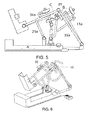
- Figures 3 and 4 show a continuous passive motion device for the knee according to an embodiment of the invention in an extended position of the leg. This embodiment may be mounted for the left leg.
- Figure 3 shows a perspective view and figure 4 a side view.
- the device may be for knee, the proximal member is thus the femur and the distal member is the tibia.
- the device may comprise a base 3, means for inducing a flexion-extension movement of the leg such as described in connection with figure 2 and means for inducing a slide 10, 20 which will be described later.
- Figures 2 and 3 show that the base 3 may be firmly arranged on a flat surface and may comprise a control 5 (wireless or connected to the base 3 by means of a cable as it is drawn).
- the base 3 may comprise an extension 6. Such an extension 6 may be telescopic.
- the base 3 of the device may further comprise means for adjusting the length of the extension 6 to different leg lengths. Said means for adjusting the length of the extension 6 may for example be a screw 7.
- Figures 2 and 3 further show that each bar of the pair of parallel bars 31 a, 31 b of the femur support may have a different length.
- the longest bar 31 a may be articulated to the extension of the base 3.
- Said longer bar 31 a may be that in which an outer area of the leg is supported. This way, the internal area of the leg, at the height of the hip joint 30a, is left free, thus being more comfortable for the user; the final weight of the device is furthermore reduced.
- both bars 31 a, 31 b may have the same length, whereby the device may be more stable.
- the extension 6 of the base may comprise a rod adjustable in length. Said rod may be inserted into holes 300 of the base 3.
- the base 3 may thus comprise at least two holes 300, right and left, in which the extension may be inserted, according to the leg, left or right, being rehabilitated.
- the base 3 may comprise a top area or surface 301.
- Said top surface 301 may comprise a track, groove or guide 8 arranged longitudinally. Along the track 8 a first 12 and a second 4 displaceable elements may move.
- the first displaceable element 12 may drive the first means for inducing a slide 10 and the second displaceable element 4 may drive the means for inducing the flexion-extension movement 50.
- the first means for inducing a slide 10 may comprise a femur support 11.
- a femur support 11 may be pivotally mounted by one of its ends 111 at the first pivot point 30a of the means for inducing the flexion-extension movement 50, i.e. at the hip joint. This way, the femur support 11 may move around the first pivot point 30a separately from the movement of the femur support 31 of the means for inducing a flexion-extension movement 50.
- the femur support 11 may comprise a pair of parallel bars 11a, 11 b which may be joined at its end 112, opposite to the end 111, by a "U" shaped profile 14. Said "U" shaped profile 14 may be hinged to the first displaceable element 12 by means of a rigid bar 13 (see also figures 8a and 8b ).
- the rigid bar 13 may be replaced by a hydraulic cylinder (reference 19 in figures 8c and 8e ) and the first displaceable element may coincide with the second displaceable element 4 which actuates the means for inducing the flexion-extension movement 50 (see figures 8c and 8e ).
- the hydraulic cylinder (19a reference of figure 8f ) may be attached to a pivot point of the means for inducing the flexion-extension movement that, in use, may be associated to the joint 30b (see figure 8f ).
- each bar of the pair of parallel bars 11a, 11 b may have a different length.
- the longest bar 11a may be hinged to the base 3 (or an extension 6 of the base) and may be that in which the outer area of the leg lies.
- the femur support 11 may further comprise an "L" shaped profile 15, horizontally arranged with the short stroke of the "L” downwards. Said short stroke may be coupled to the shorter bar 11 b of the support 11, leaving the long stroke of the "L” in contact with the top of the leg. This way, the side contacting the outer area of the leg is left open thereby facilitating rehabilitation with drains placed.
- the rigid bar 13 may be doubly articulated, to the "U" shaped profile 14 of the femur support 11 and to the first displaceable element 12.
- Figure 3 further shows that the device may further comprise second means for inducing a slide 20 comprising a support for the tibia 21.
- the tibia support 21 may be articulated at one end 212 to a second pivot point 30c of the means for inducing the flexion-extension movement 50 wherein a footrest 40 also articulates.
- the tibia support 21 may thus pivot separately from the tibia support 34 of the means for inducing a flexion-extension movement 50.
- the tibia support 21 may comprise a pair of parallel bars 21 a and 21 b joined at one end 211, opposite to the end 212, by a "U" shaped profile 24.
- a "U" shaped profile 24 may be hinged to the first displaceable element 12 by means of a hydraulic cylinder 23 (see also figure 8e ).
- the "U" shaped profile 24 may be hinged to a third displaceable element 29 by means of a rigid bar 23a (see figure 8d ).
- the hydraulic cylinder reference 23b of figure 8f
- the tibia support 21 may also comprise an "L" shaped profile 25 horizontally arranged with the short stroke of the "L “downwards.
- Such a short stroke may be coupled to one of the bars of the tibia support 21, namely the bar 21 b which supports the inside area of the leg, leaving the long stroke of the "L” in contact with the top area of the leg.
- the "L" shaped profiles 15, 25 of the femur and tibia supports 11 and 21 may be mounted on one or another bar of the pair of bars 11a, 11 b and 21 a, 21 b.
- the two bars of the pair of rods 11a, 11 b may also be interchangeable, in those embodiments in which they do not have an equal length.
- both "U” shaped profiles 14, 24 and “L” shaped profiles 15, 25 may be rigid profiles that may comprise pads or any other padding element allowing covering the profiles at least partially, so as to convert them into a comfortable element to, for example, a leg.
- the "L" shaped profiles 15, 25 may be mounted so that they can slide along a slot 16, 26 provided in a housing 17, 27 of the bar 11b, 21 b of the pair of bars on which the "L” shaped profiles are mounted 15, 25.
- This sliding may be regulated, for example, by means of a screw 18, 28 (see also figure 4 ).
- these "L” shaped profiles remain slidably mounted on the femur 11 and tibia 21 supports and may be adjusted to the length of the proximal and distal members (femur and tibia) they withstand.
- Figures 4 and 5 show respective side views of one embodiment of the device in extension and flexion respectively. Comparison of both figures show that, in order to move from the extended position ( figure 4 ) to the flexed position ( figure 5 ), the first displaceable element 12 and the second displaceable element 4 are moved along the slot (reference 8 of figure 3 ) in the direction of arrow A (distal-proximal direction for flexion and proximal-distal direction for extension).
- Said movement may cause the rigid bar 13 to push the "U" shaped profile 14 of the femur support 11. Due to this push, the femur support can rotate around the first pivot point 30a (hip-femur joint). Such a rotation results, in the femur-tibia joint 30b area (i.e. at the knee joint itself) in a displacement d1 of the bars 11a and 11b of the femur support 11 of the first means for inducing a slide 10 with respect to the bars 31 a and 31 b of the femur support 31 of the means for inducing a flexion-extension movement 50.
- the displacement d1 is in a posteroanterior direction in the sagittal plane during flexion and in an anteroposterior direction (arrow B in figure 5 ) during extension.
- the displacement may further cause the hydraulic cylinder 23 to push the "U" shaped profile 24 of the tibia support 21. Because of this push, the tibia support can rotate about the second pivot point 30c (tibia-foot or ankle joint). Such a rotation results, in the femur-tibia joint 30b area (i.e. at the knee joint itself) in a displacement d2 of the bars 21 a and 21 b of the tibia support 21 of the second means for inducing a slide 20 with respect to the bars 34a and 34b of the tibia support 3 of the means for inducing a flexion-extension movement 50. Displacement d2 is in an anteroposterior direction in the sagittal plane during flexion and in a posteroanterior direction (arrow C in figure 5 ) during extension.
- Some parameters of the device for example the length of the rigid bar 13 or the distance between the displaceable elements 4, 12, 29 or the speed of displacement of the displaceable elements 4, 12, 29 are adjustable so as to enable the means for inducing the slide 10, 20 to cause an adequate slide.
- an adequate slide is a slide that maintains the distance between the articular surfaces during rotation of the joint.
- the pivot points 30a, 30b, 30c of the device may be placed at the height of the centers of the hip joint, knee joint and ankle joint respectively.
- Figure 6 shows a device comprising means for inducing a flexion-extension movement 50 and first means for inducing a slide 10.
- This embodiment does not include second means for inducing a slide action on the tibia as the device of the previous embodiment. The remainder of its operation corresponds to that described in connection with figures 3 to 5 .
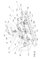
- Figure 7 shows an exploded view of the device of figure 6 in which certain components, such as the first displaceable element 12 or the second displaceable element 4 among others are shown in detail.
- Figures 6 and 7 show an embodiment in which the first displaceable element 12 and the second displaceable element 4 may be joined together (see also figure 8a ).
- This binding is achieved, for example, by mounting both displaceable elements 4, 12 on the same platform 9.
- Said platform 9 may be provided with means for slidably coupling to the track or groove 8 arranged on the top surface 301 of the base 3.
- the means for slidably coupling to the track 8 may comprise a protrusion 90 arranged on a top surface of the platform 9.
- the protrusion 90 may comprise, in its upper part, a frame 91 having a dovetail longitudinal slot shape and a pair of side flanges 92 (or projections) protruding from a bottom part the frame 91.
- These side flanges 92 and a top surface of the platform 90 define a lateral slot (schematically indicated by arrow 93).
- Said lateral slot 93 may be fitted into a sidewall of the track or slot 8.
- first displaceable element 12 may comprise a pair of parallel plates 121 each provided with a hole 122 for a hinged coupling to the rigid bar 13 that articulates with the femur support 11.
- the first displaceable element 12 may further comprise a dovetail shaped profile 123 which may fit into the dovetail slot of the frame 91 of the platform 90.
- the first displaceable element 12 may also comprise adjustment means 124 (e.g. a screw) of the dovetail shaped profile 123 to the frame 91. This way, the distance between the first displaceable element 12 and the second displaceable element 4 may be adjusted (increase or decrease), in those embodiments in which they are attached (see also figure 8a ).
- adjustment means 124 e.g. a screw
- the second displaceable element 4 may comprise a pair of parallel plates or lugs 401 provided with a pair of holes 402 for a hinged coupling with the "U" shaped profile 35 of the tibia support 34.
- the platform 90 may comprise a hole 94 through which a shaft, threaded or not (not drawn) may pass allowing platform 90 to move along said axis. Said shaft may be provided with stops for limiting the movement of the platform 90.
- the platform 90 may also be driven (in the sense of arrow A of figures 4 and 5 ) by a pneumatic cylinder.
- the movement of the platform 90 implies a movement of the means for inducing a flexion-extension movement and the first means for inducing a slide.
- the platform could also actuate the second means for inducing a slide, in those embodiments in which such means are attached to the first means for inducing a slide ( figures 3 to 5 ).
- the platform may comprise two or three separate sections, one for the means for inducing the flexion-extension movement, one for the first means for inducing a slide and / or another for the second means for inducing a slide.
- Embodiments in which, for example, the first and second means for inducing a slide are actuated from the same displaceable element and the means for inducing the flexion-extension movement are provoked from another displaceable element are also possible.
- the speed of the displaceable elements may be adjustable.
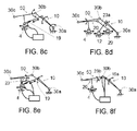
- Figures 8a - 8c show diagrams of some possible embodiments in which the means for inducing a slide only comprise fist means for inducing a slide and figures 8d - 8f show diagrams of some possible embodiments in which the means for inducing a slide comprise first and second means for inducing the slide.
- Figure 8a thus shows an embodiment in which the means for inducing a flexion-extension movement 50 may be driven from a second displaceable element 4, the first means for inducing a slide 10 may be actuated from a first displaceable element 12 attached to said means 10 by a rigid bar 13 and the first displaceable element 12 may be joined to the second displaceable element 4.
- Figure 8b shows an embodiment which differs from the previous one ( figure 8a ) in that the first displaceable element 12 may not be attached to the second displaceable element 4 and both may be moved in a synchronized manner.
- Synchronization positively contributes so that at the joint, the flexion-extension movement is accompanied by a slide between both articular surfaces.
- Figure 8c shows an embodiment in which the means for inducing a flexion-extension movement 50 may be driven from a second displaceable element 4 and the first means for inducing a slide 10 may be driven from the same second displaceable element 4 via a hydraulic cylinder 19.
- Figure 8d shows an embodiment in which the means for inducing a flexion-extension movement 50 may be driven from a second displaceable element 4, the first means for inducing a slide 10 may be actuated from a first displaceable element 12 attached to said means 10 by a rigid bar 13 and the second means for inducing a slide 20 may be driven from a third displaceable element 29 joined to said means 20 by another rigid bar 23a.
- the three displaceable elements 12, 4 and 29 may act in synchrony.
- Figure 8e outlines an embodiment which differs from the previous one ( figure 8d ) in that the first means for inducing a slide 10 and the second means for inducing a slide 20 may be actuated from two separate hydraulic cylinders 19 and 23 joined to the second displaceable element 4 of the means for inducing the flexion-extension movement 50.
- figure 8f outlines an embodiment which differs from the previous ones in that the hydraulic cylinders 19a and 23b that drive the first 10 and second 20 means for inducing a slide may be joined to a pivot point 30b of the means for inducing the flexion-extension movement that, in use, may be associated with the joint itself (femur-tibia).
- the displaceable elements may comprise a cart with wheels at the bottom.
- the track or guide may comprise stops to limit its displacement.
- the device of the present invention may be powered by any electric power source or battery.
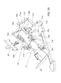
- Figures 9 and 10 are perspective views of this further embodiment, in extended position and in flexed position, respectively.
- This embodiment has some elements which are similar to the previously described embodiments in which not great emphasis will be done.
- means for inducing a flexion-extension movement 50' may include a first pivot point 30a' associated in a specific case to the hip joint, a second pivot point 30c' associated in a specific case to the ankle joint, and displaceable on the base 3' as in the case of the previous embodiment, and a pivot point 30b' associated in a specific case to the femur-tibia joint itself.
- the means for inducing the flexion-extension movement 50' may comprise a support for the tibia 34' with a pair of first parallel bars 34a', 34b' (joined by rigid bars to the pivot point 30c') and a support for the femur 31', which in this case comprises an articulated parallelogram at each side 31 a', 31 b', in order to allow the patient to adopt a proper position, with the hip furthest from the pivot point 30a'.
- These articulated parallelograms include a pair of second bars 31 a", 31 b" of which figure 9 only shows the second bar 31 a": this bar may be bent at its two ends, and may extend between the pivot point 30a' and a pivot point 31a"' in which the second bar 31 a" is articulated to a point of the first bar 34a'.
- the bar 31 b" is mounted in the same way, on the other side of the device.
- the device comprises means 20' for inducing a slide between the two articular surfaces during the flexion-extension movement that, in this case, may comprise a support 21' for the tibia; this support 21' may extend parallel to the pair of first bars 34a', 34b', and be mounted on these first bars so as to be displaceable with respect to these bars in a direction substantially perpendicular to its direction, as will be explained later.
- the support 21' may comprise a pair of parallel bars 21 a', 21 b', of which, in figures 9 and 10 , bar 21 b' is clearly visible, while much of the bar 21 a' is hidden behind the bar 34a'.
- the support 21' may further comprise a first fastening piece 25' for the tibia, which may extend between the two bars 21 a', 21 b', and a second fastening piece 26', which may have a coupler 27' for engagement by fitting into one of two corresponding hooks 28' integral with the bars 21 a', 21 b', so that it can be mounted in each case at the most convenient side of the device.
- the second fastening piece 26' may have a hinge for closing in order to clamp the tibia between the pieces 25' and 26'.
- the foot support 40' may be articulated.
- the support 21' for the tibia may be mounted with respect to the bars 34a', 34b' in the manner described following.
- guides 60' may be mounted in which corresponding runners 61' may slide that are integral with the bars 21 a', 21 b', so as to allow and guide the displacement of the support 21' in a direction perpendicular to the pair of first bars 34a', 34b'.
- the support 21' may be coupled to the first bars 34a', 34b' using a cam unit 70' which provokes their distancing from the first bar during a flexion movement of the device.
- the cam unit 70' may comprise two similar parts 70a', 70b', one at each side of the device, which may be interposed between the first bars 34a', 34b' and the bars 21 a', 21 b' of the support 21' respectively.
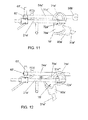
- cam unit 70' Details related to the cam unit 70' will be better understood with reference to figures 11 and 12 showing an enlarged view of the cam unit 70' in the same extended and flexed positions of figures 9 and 10 .
- the part 70a' of the cam unit 70' may be associated to the pivot point 31a"' mentioned above, and may comprise a cam surface 71 a' made in the same (hidden and drawn in dashed lines in figures 9 and 11 ), in which a cam follower 72a' integral with the bar 21 a' may slide.
- Part 70b' of the cam unit 70' (visible in figures 9 and 10 ) is mounted in a similar manner and the set may comprise means (not shown) to ensure synchronization between the two parts.
- Part 70a' of the cam unit 70' may be associated to the pivot point 31 a"' so that, when using the device in a rehabilitation, the cam unit 70' rotates together with the bar 31 a"; a particular manner in which the coupling between the part 70a' and the bar 31 a" may be carried out will be explained later.
- the shape of the cam surface 71 a' may be appropriate such that the follower 72a' drag the bar 21 a' and displace it in a direction perpendicular to the bar 34a', so that during the flexion-extension movement the support 21' may displace the tibia perpendicularly to the pair of bars 34' thus causing a slippage between the two articular surfaces.
- the cam surface may lead to the distancing of the support 21' of the pair of bars 34' (in the direction of arrow D in figure 12 ) during a flexion movement, as can be seen by comparing figures 11 and 12 .
- the cam surface 71 a' may have substantially the shape of a portion of an ellipse. It has been found that an elliptical shape allows the slide induced between the articular surfaces for each flexion angle to be closer to the values recommended in the literature.
- the angle of rotation of the cam unit 70' associated to the pivot point 31 a"' essentially coincides with the rotation angle of the pivot point 30a': i.e., that corresponding to the joint between the tibia and the femur which is the object of the rehabilitation. Mounting the associated cam to the pivot point 31 a"' allows maintaining free the pivot point 30a', for example, for a sensor of the rotated angle during flexion.
- the cam unit may have an adjustable position, so that each mounting position of the cam unit corresponds to a magnitude of displacement of the displaceable support 21' with respect to the pair of bars 34' during the flexion movement.
- the cam unit 70' is rotatably mounted about a point (not visible in the figures) of the bar 34a', and the device comprises a pair of auxiliary plates, of which the plate 80a' is visible in figures 9 to 12 .
- the auxiliary plate 80a' may be integral to the bar 31 a" by flanges and there may be means for adjusting the position of the cam unit 70' with respect to the plate 80a': for example, the figures show an embodiment with a hole in the plate 80a', a series of holes 81 a' made in the part 70a' of the cam unit 70', and a pin 82a' intended to be inserted through the holes to fix the relative position of the two parts 70a', 80a', and therefore the position of the cam unit 70' relative to the bar 31 a".
- the invention further relates to a kit allowing expanding a conventional rehabilitation device comprising means for inducing a flexion-extension movement of the joint, so that it can also induce a slide between both articular surfaces.
- kits comprises means for inducing a slide between both articular surfaces, destined to act on one of the members of the joint during the flexion-extension movement, and means for coupling to the device, in accordance with figures 9 to 12 , the kit may comprise the movable support 21' and the cam unit 70' for coupling said movable support to the pair of first bars 34', so that said support is displaceable in a direction substantially perpendicular to said pair of bars 34', as described above.
- the kit may also comprise other suitable elements for mounting the movable support 21' and the cam unit 70', such as the guides 60', the runners 61', the auxiliary plates, etc..
- Figure 13 schematically shows a method of adapting a kit to a conventional rehabilitation device comprising means for inducing a flexion-extension movement of the joint.
- the method may comprise to free the foot support 40', to mount the guides 60', to install the cam unit 70' (with its auxiliary plate if applicable), to mount the support 21' for the tibia between the cam unit 70' and the guide 60', and to place the foot support 40' at the end of the support 21' for the tibia.
- kit analogous to that described with reference to figure 13 could also be used to adapt or expand other conventional devices, for example that shown in figure 2 , with the kinematic, mechanical, etc... modifications that may be required.
Landscapes
- Health & Medical Sciences (AREA)
- Epidemiology (AREA)
- Pain & Pain Management (AREA)
- Physical Education & Sports Medicine (AREA)
- Rehabilitation Therapy (AREA)
- Life Sciences & Earth Sciences (AREA)
- Animal Behavior & Ethology (AREA)
- General Health & Medical Sciences (AREA)
- Public Health (AREA)
- Veterinary Medicine (AREA)
- Prostheses (AREA)
- Orthopedics, Nursing, And Contraception (AREA)
- Rehabilitation Tools (AREA)
Applications Claiming Priority (2)
| Application Number | Priority Date | Filing Date | Title |
|---|---|---|---|
| ES201131342A ES2398426B1 (es) | 2011-08-01 | 2011-08-01 | Dispositivo de movimiento pasivo continuo |
| PCT/ES2012/070600 WO2013017726A2 (es) | 2011-08-01 | 2012-08-01 | Dispositivo de movimiento pasivo continuo |
Publications (1)
| Publication Number | Publication Date |
|---|---|
| EP2740457A2 true EP2740457A2 (de) | 2014-06-11 |
Family
ID=47116039
Family Applications (1)
| Application Number | Title | Priority Date | Filing Date |
|---|---|---|---|
| EP12780217.1A Withdrawn EP2740457A2 (de) | 2011-08-01 | 2012-08-01 | Vorrichtung für kontinuierliche passive bewegung |
Country Status (3)
| Country | Link |
|---|---|
| EP (1) | EP2740457A2 (de) |
| ES (1) | ES2398426B1 (de) |
| WO (1) | WO2013017726A2 (de) |
Cited By (4)
| Publication number | Priority date | Publication date | Assignee | Title |
|---|---|---|---|---|
| CN107184363A (zh) * | 2017-06-02 | 2017-09-22 | 上海交通大学 | 坐式被动膝关节康复机 |
| EP3287114A1 (de) * | 2016-08-26 | 2018-02-28 | Samsung Electronics Co., Ltd | Bewegungsassistenzvorrichtung |
| EP3419569A4 (de) * | 2016-02-24 | 2019-10-30 | Richard Stewart | Kniebereich einer bewegungsvorrichtung |
| WO2022182181A1 (ko) * | 2021-02-24 | 2022-09-01 | 주식회사 네오펙트 | 재활기구 및 재활운동 시스템 |
Citations (1)
| Publication number | Priority date | Publication date | Assignee | Title |
|---|---|---|---|---|
| US6221033B1 (en) * | 1999-11-09 | 2001-04-24 | Chattanooga Group, Inc. | Continuous passive motion device that accelerates through the non-working range of motion |
Family Cites Families (11)
| Publication number | Priority date | Publication date | Assignee | Title |
|---|---|---|---|---|
| US4520827A (en) * | 1984-02-09 | 1985-06-04 | Empi, Inc. | NMS aided continuous passive motion apparatus |
| US4665899A (en) | 1984-09-27 | 1987-05-19 | Joint Mobilizer Systems Corp. | Apparatus for articulating the knee and hip joints |
| US4671257A (en) | 1985-01-23 | 1987-06-09 | Invacare Corporation | Continuous passive motion exercise apparatus |
| US4825852A (en) * | 1986-10-31 | 1989-05-02 | Sutter Biomedical, Inc. | Continuous passive motion device |
| US4834073A (en) * | 1987-02-20 | 1989-05-30 | Medical Technology, Inc. | Passive motion exerciser |
| US4974830A (en) * | 1989-01-19 | 1990-12-04 | Sutter Corporation | Continuous passive motion device |
| US5547464A (en) * | 1990-03-16 | 1996-08-20 | Deroyal Industries, Inc. | Joint device |
| US5228432A (en) | 1991-09-16 | 1993-07-20 | Jace Systems, Inc. | Continuous passive motion orthosis device for a limb |
| US5280783A (en) * | 1992-09-29 | 1994-01-25 | Sutter Corporation | Continuous passive motion device for full extension of leg |
| US7175602B2 (en) * | 2004-05-10 | 2007-02-13 | Robert Diaz | Portable therapy device |
| US20090227911A1 (en) * | 2008-03-06 | 2009-09-10 | Srivastava Varad N | Biometric and low restraint continuous passive motion rehabilitation device |
-
2011
- 2011-08-01 ES ES201131342A patent/ES2398426B1/es not_active Expired - Fee Related
-
2012
- 2012-08-01 WO PCT/ES2012/070600 patent/WO2013017726A2/es not_active Ceased
- 2012-08-01 EP EP12780217.1A patent/EP2740457A2/de not_active Withdrawn
Patent Citations (1)
| Publication number | Priority date | Publication date | Assignee | Title |
|---|---|---|---|---|
| US6221033B1 (en) * | 1999-11-09 | 2001-04-24 | Chattanooga Group, Inc. | Continuous passive motion device that accelerates through the non-working range of motion |
Non-Patent Citations (1)
| Title |
|---|
| See also references of WO2013017726A2 * |
Cited By (5)
| Publication number | Priority date | Publication date | Assignee | Title |
|---|---|---|---|---|
| EP3419569A4 (de) * | 2016-02-24 | 2019-10-30 | Richard Stewart | Kniebereich einer bewegungsvorrichtung |
| EP3287114A1 (de) * | 2016-08-26 | 2018-02-28 | Samsung Electronics Co., Ltd | Bewegungsassistenzvorrichtung |
| US10688009B2 (en) | 2016-08-26 | 2020-06-23 | Samsung Electronics Co., Ltd. | Motion assistance apparatus |
| CN107184363A (zh) * | 2017-06-02 | 2017-09-22 | 上海交通大学 | 坐式被动膝关节康复机 |
| WO2022182181A1 (ko) * | 2021-02-24 | 2022-09-01 | 주식회사 네오펙트 | 재활기구 및 재활운동 시스템 |
Also Published As
| Publication number | Publication date |
|---|---|
| ES2398426B1 (es) | 2014-05-08 |
| WO2013017726A2 (es) | 2013-02-07 |
| ES2398426R1 (es) | 2013-07-11 |
| WO2013017726A3 (es) | 2013-08-08 |
| ES2398426A2 (es) | 2013-03-19 |
Similar Documents
| Publication | Publication Date | Title |
|---|---|---|
| KR100936621B1 (ko) | 하지 운동 재활 기구 | |
| KR101059828B1 (ko) | 골절 환자용 회복운동장치 | |
| KR102606960B1 (ko) | 손목 운동 장치 및 이를 이용한 상지 및 하지용 재활 운동 장치 | |
| US10420691B2 (en) | Knee range of motion device utilizing tangential joint translation and distraction | |
| KR100942968B1 (ko) | 재활치료용 운동기구 | |
| US5280783A (en) | Continuous passive motion device for full extension of leg | |
| CN209059884U (zh) | 一种可穿戴式下肢康复机器人 | |
| AU2017258838B2 (en) | Method and apparatus for knee joint flexibility rehabilitation | |
| EP2740457A2 (de) | Vorrichtung für kontinuierliche passive bewegung | |
| CN104665963A (zh) | 仿生膝关节 | |
| CN109620653A (zh) | 一种融合自适应膝关节的下肢外骨骼结构及机器人 | |
| KR100465108B1 (ko) | 골절 환자의 회복운동장치 | |
| Sui et al. | Analysis and synthesis of ankle motion and rehabilitation robots | |
| CN208464572U (zh) | 一种便携式肘部及手部外骨骼辅助训练机器人 | |
| EP2299947B1 (de) | Unterstützende vorrichtung zur einnahme der korrekten haltung der unteren gliedmassen und zur fortsetzung der gehaktivität | |
| CN216294603U (zh) | 一种全关节镜下治疗关节内韧带止点撕脱骨折装置 | |
| JP2020192124A (ja) | 他動運動装置 | |
| US20180280180A1 (en) | Joint mechanism | |
| KR100936620B1 (ko) | 하지 운동 재활 기구 | |
| CN212466289U (zh) | 一种无源的髋关节限位辅助支撑器 | |
| KR20220141963A (ko) | 상지관절 재활훈련장치 및 이의 제어방법 | |
| CN207693749U (zh) | 一种开放式角度可调膝关节固定器 | |
| KR102835318B1 (ko) | 하지 재활 운동 장치 | |
| CN114652565A (zh) | 膝关节刺激装置 | |
| CN114129395A (zh) | 下肢关节康复训练器 |
Legal Events
| Date | Code | Title | Description |
|---|---|---|---|
| PUAI | Public reference made under article 153(3) epc to a published international application that has entered the european phase |
Free format text: ORIGINAL CODE: 0009012 |
|
| 17P | Request for examination filed |
Effective date: 20140303 |
|
| AK | Designated contracting states |
Kind code of ref document: A2 Designated state(s): AL AT BE BG CH CY CZ DE DK EE ES FI FR GB GR HR HU IE IS IT LI LT LU LV MC MK MT NL NO PL PT RO RS SE SI SK SM TR |
|
| DAX | Request for extension of the european patent (deleted) | ||
| STAA | Information on the status of an ep patent application or granted ep patent |
Free format text: STATUS: EXAMINATION IS IN PROGRESS |
|
| 17Q | First examination report despatched |
Effective date: 20161021 |
|
| STAA | Information on the status of an ep patent application or granted ep patent |
Free format text: STATUS: THE APPLICATION IS DEEMED TO BE WITHDRAWN |
|
| 18D | Application deemed to be withdrawn |
Effective date: 20210302 |