EP2740564B1 - Verfahren und Systeme zur Beschichtung und Abdichtung in Rohrleitungssystemen - Google Patents
Verfahren und Systeme zur Beschichtung und Abdichtung in Rohrleitungssystemen Download PDFInfo
- Publication number
- EP2740564B1 EP2740564B1 EP13177669.2A EP13177669A EP2740564B1 EP 2740564 B1 EP2740564 B1 EP 2740564B1 EP 13177669 A EP13177669 A EP 13177669A EP 2740564 B1 EP2740564 B1 EP 2740564B1
- Authority
- EP
- European Patent Office
- Prior art keywords
- approximately
- pipes
- barrier coating
- epoxy
- piping system
- Prior art date
- Legal status (The legal status is an assumption and is not a legal conclusion. Google has not performed a legal analysis and makes no representation as to the accuracy of the status listed.)
- Active
Links
Images



Classifications
-
- F—MECHANICAL ENGINEERING; LIGHTING; HEATING; WEAPONS; BLASTING
- F16—ENGINEERING ELEMENTS AND UNITS; GENERAL MEASURES FOR PRODUCING AND MAINTAINING EFFECTIVE FUNCTIONING OF MACHINES OR INSTALLATIONS; THERMAL INSULATION IN GENERAL
- F16L—PIPES; JOINTS OR FITTINGS FOR PIPES; SUPPORTS FOR PIPES, CABLES OR PROTECTIVE TUBING; MEANS FOR THERMAL INSULATION IN GENERAL
- F16L58/00—Protection of pipes or pipe fittings against corrosion or incrustation
- F16L58/02—Protection of pipes or pipe fittings against corrosion or incrustation by means of internal or external coatings
- F16L58/04—Coatings characterised by the materials used
- F16L58/10—Coatings characterised by the materials used by rubber or plastics
- F16L58/1009—Coatings characterised by the materials used by rubber or plastics the coating being placed inside the pipe
- F16L58/1027—Coatings characterised by the materials used by rubber or plastics the coating being placed inside the pipe the coating being a sprayed layer
-
- F—MECHANICAL ENGINEERING; LIGHTING; HEATING; WEAPONS; BLASTING
- F16—ENGINEERING ELEMENTS AND UNITS; GENERAL MEASURES FOR PRODUCING AND MAINTAINING EFFECTIVE FUNCTIONING OF MACHINES OR INSTALLATIONS; THERMAL INSULATION IN GENERAL
- F16L—PIPES; JOINTS OR FITTINGS FOR PIPES; SUPPORTS FOR PIPES, CABLES OR PROTECTIVE TUBING; MEANS FOR THERMAL INSULATION IN GENERAL
- F16L55/00—Devices or appurtenances for use in, or in connection with, pipes or pipe systems
- F16L55/16—Devices for covering leaks in pipes or hoses, e.g. hose-menders
- F16L55/162—Devices for covering leaks in pipes or hoses, e.g. hose-menders from inside the pipe
- F16L55/164—Devices for covering leaks in pipes or hoses, e.g. hose-menders from inside the pipe a sealing fluid being introduced in the pipe
-
- B—PERFORMING OPERATIONS; TRANSPORTING
- B05—SPRAYING OR ATOMISING IN GENERAL; APPLYING FLUENT MATERIALS TO SURFACES, IN GENERAL
- B05D—PROCESSES FOR APPLYING FLUENT MATERIALS TO SURFACES, IN GENERAL
- B05D7/00—Processes, other than flocking, specially adapted for applying liquids or other fluent materials to particular surfaces or for applying particular liquids or other fluent materials
- B05D7/22—Processes, other than flocking, specially adapted for applying liquids or other fluent materials to particular surfaces or for applying particular liquids or other fluent materials to internal surfaces, e.g. of tubes
- B05D7/222—Processes, other than flocking, specially adapted for applying liquids or other fluent materials to particular surfaces or for applying particular liquids or other fluent materials to internal surfaces, e.g. of tubes of pipes
Definitions
- This invention relates to repairing leaks in pipes , and in particular to methods, systems and apparatus for repairing leaks and providing barrier protective coatings in a single operation to the interior walls of small diameter metal and plastic pressurized pipes such as pressurized drain lines, hot water lines, cold water lines, potable water lines, natural gas lines, HVAC piping systems, and fire sprinkler system lines, and the like, that are used in multi-unit residential buildings, office buildings, commercial buildings, and single family homes, and the like.
- pressurized drain lines hot water lines, cold water lines, potable water lines, natural gas lines, HVAC piping systems, and fire sprinkler system lines, and the like
- piping systems such as those used in commercial buildings, apartment buildings, condominiums, as well as homes and the like that have a broad base of users commonly develop problems with their pipes such as their water and plumbing pipes, and the like.
- the repair method may involve a number of separate applications. Those repair applications may involve a specific repair to the area of failure such as replacing that section of pipe or the use of a clamping devise and a gasket.
- Hilbush '148 describes a process for sealing laid gas pipes by blowing in a foamed sealing emulsion.
- the foam settles on the internal wall and condenses there. In the case of leaks, it tends to settle in larger quantities which makes this technique unsuitable for many applications.
- This method is expressly suited only to gas pipes; solid additions to the sealing emulsion are neither taught nor made obvious.
- Marx ,'412 describes a repair process in which the portion of the pipe with the leak is sealed at the front and rear ends. A specially stabilized emulsion is then pressed in which issues at the leak, is destabilized there and coagulates so that the leak is sealed. Actual solid sealing materials are not therefore pressed into the pipes and the vehicle is water, not gas.
- Stang '409 describes the sealing of leaks in laid pipes by very fine substances having a high capillary action.
- the very fine and difficult to use substance is arranged externally at the leak and is watered there.
- the capillary pressure thus obtained counteracts the delivery pressure of the medium flowing in the pipe.
- the very fine insulating material must be laid onto the conduit from the exterior, after excavation of the leak.
- Koga '613 describes a process and an apparatus for the internal repair of laid pipes by means of "plastic mist" conveyed in a gas stream. It is unclear whether actual leaks are also sealed with it. More importantly, this process does not appear to be able to immediately produce the plastic mist necessary to work.
- Naf '209 describes s process where a sealant is introduced with water and is part of a water sealant mixture.
- the water sealant mixture fills a pipe resulting in adding multiple steps to the process of filling, setting up a hydraulic recirculating system, draining and drying the piping system.
- the water/sealant mixture may also flow from the leaking section creating water damage to the immediate area. Further methods of pipe renovation are shown in US 2004/0132 387 A1 and EP 0 299 134 B1 .
- None of the prior art techniques describe a process where a barrier coating and leaks are sealed with a barrier coating application combined with a leak sealing operation.
- a primary objective of the invention is to provide methods, systems and devices for repairing interior walls and sealing leaks of pressurized pipes in buildings without having to physically remove and replace the pipes, where the leaks are sealed and the barrier coating is applied in a single operation.
- a secondary objective of the invention is to provide methods, systems and devices for repairing interior walls and sealing leaks, in a single operation in pipes by initially cleaning the interior walls of the pipes.
- a third objective of the invention is to provide methods, systems and devices for repairing interior walls and sealing leaks, in a single operation in pipes by applying a corrosion protection barrier coating to the interior walls of the pipes that provides a barrier coating and seals leaks in one operation.
- a fourth objective of the invention is to provide methods, systems and devices for repairing interior walls and sealing leaks, in a single operation, in pipes in buildings in a cost effective and efficient manner.
- a fifth objective of the invention is to provide methods, systems and devices for repairing interior walls and sealing leaks, in a single operation, in pipes which is applicable to small diameter piping systems from approximately 3/8" to approximately 6" in diameter in piping systems made of various materials such as galvanized steel, black steel, lead, brass, copper or other materials such as PVC, and composites including plastics, as an alternative to pipe replacement or repair.
- a sixth objective of the invention is to provide methods, systems and devices for repairing interior walls and sealing leaks in pipes, in a single operation which is applied to pipes, "in place” or insitu minimizing the need for opening up walls, floors ceilings, or grounds.
- a seventh objective of the invention is to provide methods, systems and devices for repairing interior walls and sealing leaks in pipes, in a single operation, which minimizes the disturbance of asbestos lined piping or walls/ceilings that can also contain lead based paint or other harmful materials.
- An eighth objective of the invention is to provide methods, systems and devices for repairing interior walls and sealing leaks in pipes, in a single operation, where once the existing piping system is restored with a durable epoxy barrier coating the common effects of corrosion from water passing through the pipes will be delayed if not stopped entirely.
- a ninth objective of the invention is to provide methods, systems and devices for repairing interior walls and sealing leaks in pipes, in a single operation, to clean out blockage where once the existing piping system is restored, users will experience an increase in the flow of water, which reduces the energy cost to transport the water. Additionally, the barrier epoxy coating leak sealant being applied to the interior walls of the pipes can create enhanced hydraulic capabilities again giving greater flow with reduced energy costs.
- a tenth objective of the invention is to provide methods, systems and devices for repairing interior walls and sealing leaks in pipes, in a single operation, where customers benefit from the savings in time associated with the restoration of an existing piping system.
- An eleventh objective of the invention is to provide methods, systems and devices for repairing interior walls and sealing leaks in pipes, in a single operation, where customers benefit from the economical savings associated with the restoration and in-place leak repair of an existing piping system, since walls, ceilings, floors, and/or grounds do not always need to be broken and/or cut through.
- a twelfth objective of the invention is to provide methods, systems and devices for repairing interior walls and sealing leaks in pipes, in a single operation, where income producing properties experience savings by remaining commercially usable, and any operational interference and interruption of income-producing activities is minimized.
- a thirteenth objective of the invention is to provide methods, systems and devices for repairing interior walls and sealing leaks in pipes, in a single operation, where health benefits had previously accrued, as the water to metal contact will be stopped by a barrier coating thereby preventing the leaching of metallic and potentially other harmful products from the pipe into the water supply such as but not limited to lead from solder joints and from lead pipes, and any excess leaching of copper, iron and lead.
- a fourteenth objective of the invention is to provide methods, systems and devices for repairing interior walls and sealing leaks in pipes, in a single operation where the pipes are being restored and repaired, in-place, thus causing less demand for new metallic pipes, which is a non-renewable resource.
- a fifteenth objective of the invention is to provide methods, systems and devices for repairing interior walls and sealing leaks in pipes, in a single operation, using a less intrusive method of repair where there is less building waste and a reduced demand on expensive landfills.
- a sixteenth objective of the invention is to provide methods, systems and devices for repairing interior walls and sealing leaks in pipes, in a single operation, where the process uses specially filtered air that reduces possible impurities from entering the piping system during the process.
- a seventeenth objective of the invention is to provide methods, systems and devices for repairing interior walls and sealing leaks in pipes, in a single operation, where the equipment package is able to function safely, cleanly, and efficiently in high customer traffic areas.
- An eighteenth objective of the invention is to provide methods, systems and devices for repairing interior walls and sealing leaks in pipes, in a single operation where the equipment components are mobile and maneuverable inside buildings and within the parameters typically found in single-family homes, multi unit residential buildings and various commercial buildings.
- a nineteenth objective of the invention is to provide methods, systems and devices for repairing interior walls and sealing leaks in pipes, in a single operation, where the equipment components can operate quietly, within the strictest of noise requirements such as approximately seventy four decibels and below when measured at a distance of approximately several feet away.
- a twentieth objective of the invention is to provide methods, systems and devices for repairing interior walls and sealing leaks in pipes, in a single operation where the barrier coating leak sealant material for application in a variety of piping environments, and operating parameters such as but not limited to a wide temperature range, at a wide variety of airflows and air pressures, and the like.
- a twenty first objective of the invention is to provide methods, systems and devices for repairing interior walls and sealing leaks in pipes, in a single operation where the barrier coating leak sealant material and the process is functionally able to deliver turnaround of restored piping systems to service within approximately twenty four hours or less.
- a twenty second objective of the invention is to provide methods, systems and devices for repairing interior walls and sealing leaks in pipes, in a single operation, where the barrier coating material is designed to operate safely under NSF (National Sanitation Foundation) Standard 61 criteria in domestic water systems, with adhesion characteristics within piping systems in excess of approximately 400 PSI.
- NSF National Sanitation Foundation
- a twenty third objective of the invention is to provide methods, systems and devices for repairing interior walls and sealing leaks in pipes, in a single operation where the barrier coating material is designed as a long-term, long-lasting, durable solution to pipe corrosion, pipe erosion, pinhole leak repair and related water damage to piping systems where the barrier coating extends the life of the existing piping system.
- a twenty fourth objective of the invention is to provide methods, systems and devices for both cleaning and coating interiors and leak sealing, the interior of pipes having diameters of up to approximately 6 inches using dry particulates, such as sand and grit, prior to coating the interior pipe walls.
- a twenty fifth objective of the invention is to provide methods, systems and devices for cleaning coating interiors and sealing leaks of pipes having diameters of up to approximately 6 inches in buildings, without having to section off small sections of piping for cleaning coating and leak sealing applications.
- a twenty sixth objective of the invention is to provide methods, systems and devices for cleaning the interiors of an entire isolated piping system in a building in a single pass run operation.
- a twenty seventh objective of the invention is to provide methods, systems and devices for barrier coating and leak sealing the interiors of an entire isolated piping system in a building in a single pass run operation.
- the novel method and system of pipe restoration prepares and protects small diameter piping systems such as those within the diameter range of approximately 3/8 of an inch to approximately six inches and can include straight and bent sections of piping from the effects of water corrosion, erosion and electrolysis and sealing leaks in-place, thus extending the life of small diameter piping systems.
- the barrier coating used as part of the novel process method and system can be used in pipes servicing potable water systems, meets the criteria established by the National Sanitation Foundation (NSF) for products that come into contact with potable water.
- NSF National Sanitation Foundation
- the epoxy material also meets the applicable physical criteria established by the American Water Works Association as a barrier coating.
- the novel method process and system allows for barrier coating and leak repair, in a single operation to potable water lines, natural gas lines, HVAC piping systems, hot water lines, cold water lines, pressurized drain lines, and fire sprinkler systems.
- Epoxy coatings are characterized by their durability, strength, adhesion and chemical resistance, making them an ideal product for their application as a barrier coating and leak sealant on the inside of small diameter piping systems.
- the novel barrier coating provides protection and extended life to an existing piping system that has been affected by erosion corrosion caused from internal burrs, improper soldering, excessive turns, and excessive water velocity in the piping system, electrolysis and "wear" on the pipe walls created by suspended solids.
- the epoxy barrier coating will create at least an approximately 4 mil covering to the inside of the piping system and will seal leaks spanning up to approximately 125 mils.
- New steel pipes are treated with various forms of barrier coatings to prevent or slow the effects of corrosion.
- the most common barrier coating used on steel pipe is the application of a zinc based barrier coat commonly called galvanizing.
- New copper pipe has no barrier coating protection and for years was thought to be corrosion resistant offering a lifetime trouble free use as a piping system.
- the invention can also be used with piping systems having plastic pipes, PVC pipes, composite material, and the like.
- novel method and system of corrosion control by the application of an epoxy barrier coating and sealant can be applied to existing piping systems in-place, in the same operation.
- the invention includes novel methods and equipment for providing barrier coating corrosion and a repair method for sealing leaks for the interior walls of small diameter piping systems in the same operation.
- the novel process method and system of internal leak repair and corrosion control includes at least three basic steps: Air Drying a piping system to be serviced; profiling the piping system using an abrasive cleaning agent; and applying the barrier coating leak sealant to selected coating thickness layers inside the pipes.
- the novel invention can also include two additional preliminary steps of: diagnosing problems with the piping system to be serviced, and planning and setting up the barrier coating leak repair project onsite.
- the novel invention can include a final end step of evaluating the system after applying the barrier coating leak repair and re-assembling the piping system.
- a novel method and process of applying a barrier coating leak sealant to pipes to fix openings and cracks in the pipes can include the steps of mixing an epoxy material to form a barrier coating leak sealant having a viscosity range of approximately 1,200 cps to approximately 60,000 cps at room temperature, applying the barrier coating leak sealant to interior walls of the pipes without dismantling all of the piping system, wherein the barrier coating leak sealant provides an interior barrier for protecting the interior walls of the pipes and sealing leak openings up to approximately 125 mils in diameter, and restoring the pipes of the existing piping system to service is less than approximately ninety six hours.
- a more preferable viscosity range is between approximately 10,000 cps to approximately 60,000 cps.
- the method and process can further include the step of mixing an additional filler material with the barrier coating to further fill in the leak openings.
- the filler can be additional epoxy material.
- the additional filler material can be selected from the group consisting of: glass flakes, glass fibers, epoxy fibers, mica, clay, silica, cork, and plastics.
- Approximately 100 to approximately 200 milliliters of unfilled epoxy can be used for pipes having a length of approximately 5 feet to approximately 30 feet, where the pipes are approximately 1 ⁇ 2 inch in diameter.
- Approximately 100 to approximately 300 milliliters of unfilled epoxy can be used for pipes having a length of approximately 5 feet to approximately 30 feet, where the pipes are approximately 3/4 inch in diameter.
- Approximately 100 to approximately 400 milliliters of unfilled epoxy can be used for pipes having a length of approximately 5 feet to approximately 30 feet, where the pipes are approximately 1 inch in diameter.
- Approximately 100 to approximately 500 milliliters of unfilled epoxy can be used for the pipes having a length of approximately 5 feet to approximately 30 feet, where the pipes are approximately 1 % inch in diameter.
- Approximately 100 to approximately 600 milliliters of unfilled epoxy can be used for pipes having a length of approximately 5 feet to approximately 30 feet, where the pipes are approximately 1 1/2 inch in diameter.
- Approximately 100 to approximately 700 milliliters of unfilled epoxy can be used for pipes having a length of approximately 5 feet to approximately 30 feet, where the pipes are approximately 2 inches in diameter.
- the mixed epoxy having a viscosity of approximately 1200 to approximately 5000 cps has at least approximately 25% fillers.
- the mixed epoxy having a viscosity of approximately 5001 to approximately 10000 cps has at least approximately 20% fillers.
- the mixed epoxy having a viscosity of approximately 10001 to approximately 15000 cps has at least approximately 15% fillers.
- the mixed epoxy having a viscosity of approximately 15001 to approximately 25000 cps has at least approximately 10% fillers.
- the mixed epoxy having a viscosity of approximately 25001 to approximately 60000 cps has at least approximately 5% fillers.
- the method and process include the step of applying and maintaining a positive pressure fluid, which is air, throughout the pipes to set the barrier coating for a selected time of at least several minutes, wherein the positive pressure fluid is at a pressure level of at least approximately 1.5 PSI.
- a positive pressure fluid which is air
- Fig. 1 shows the general six steps for a project overview for applying the barrier coating leak sealant to an existing piping system, which include step one, 10 program diagnosis, step two, 20 project planning, step three, 30 drying piping system, step four 40, profiling the piping system, step five, 50 applying barrier coating leak sealant to the interior walls of the pipes in the piping system, and final step six 60 evaluation and return to operation of the piping system.
- step one 10
- steps can be done to diagnose the problem with a piping system in a building, and can include:
- step one After completion of step one, 10, the project planning and setup step 20 can be started.
- step two 20
- steps can be followed for planning and setup for restoring the integrity of the piping system in a building, and can include:
- the piping system to be prepared for the coating by drying the existing pipes can include :
- the piping system is to be profiled, and can include:
- the piping system is barrier coated and leaks sealed and can include:
- the final step six, 60 allows for restoring the piping system to operation and can include:
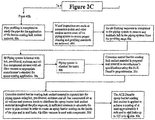
- FIGS. 2A , 2B , 2C and 2D show a detailed process flowchart using the steps of Fig. 1 for providing the barrier coating leak sealant. These flow chart figures show a preferred method of applying a novel barrier coating leak sealant for the interior of small diameter piping systems following a specific breakdown of a preferred application of the invention.
- IDENTIFIER EQUIPMENT 100 395, 850, 1100, 1600 CFM Compressors Outfitted with Aftercooler, Water separator, Fine Filter and Reheater (if required) 200 Main Air Header and Distributor (Main Header) 300 Floor Manifold (optional) 400 Sander 500 Pre-Filter 600 Dust Collector System (Air Filter Vacuum) 700 Portable Epoxy Metering and Dispensing Unit (Epoxy Mixer) 800 Epoxy Barrier Coating and Sealant 900 Epoxy Carrying Tube - Injection Device
- components 100-900 can be located and used at different locations in or around a building.
- the invention allows for an entire isolated building piping system to be cleaned in one single pass through run without having to dismantle either the entire or multiple sections of the piping system.
- the piping system can include pipes having diameters of approximately 3/8 of an inch up to approximately 6 inches in diameter with the piping including bends up to approximately ninety degrees or more throughout the building.
- the invention allows for an entire isolated building piping system to have the interior surfaces of the pipes coated and leaks sealed in one single pass through run without having to dismantle either the entire or multiple parts of the piping system.
- the air compressors 100 can provide filtered and heated compressed air.
- the filtered and heated compressed air employed in various quantities is used, to dry the interior of the piping system, as the propellant to drive the abrasive material used in cleaning of the piping system and is used as the propellant in the application of the epoxy barrier coating leak sealant and the drying of the epoxy barrier coating leak sealant once it has been applied.
- the compressors 100 also provide compressed air used to propel ancillary air driven equipment.
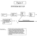
- An off the shelf main header and distributor 200 shown in Figures 3 can be one Manufactured By:Media Blast & Abrasives, Inc. 591 W. Apollo Street Brea, CA 92821.
- the Main Header 200 provides safe air management capability from the air compressor for both regulated and unregulated air distribution (or any combination thereof) to the various other equipment components and to both the piping system risers and fixture outlets for a range of piping configurations from a single family home to a multi-story building.
- the air enters through the 2" NPT inlet to service the pressure vessel.
- the main header 200 can manage air capacities ranging to approximately 1600 CFM and approximately 200 psi.
- the distributor is portable and is easy to move and maneuver in tight working environments.
- Regulator Adjustment can easily and quickly manage air capacities ranging to approximately 1600 CFM and approximately 200 psi, and vary the operating airflows to each of the other ancillary equipment associated with the invention.
- the Air Pressure Regulator and the Method of Distributing the air allows both regulated and unregulated air management from the same equipment in a user-friendly, functional manner.
- the approximately 1" Valving allows accommodation for both approximately 1" hosing and with adapters, and hose sizes of less than approximately 1"” can be used to meet a wide variety of air demand needs on a job site.
- the insulated cabinet, surrounding air works dampens noise associated with the movement of the compressed air.
- the insulated cabinet helps retain heat of the pre-dried and heated compressed air, the pre-dried and heated compressed air being an integral part of the invention.
- the insulated cabinet helps reduce moisture in the pressure vessel and air supply passing through it.
- the valving of the pressure vessel allows for delivery (separate or simultaneous) of regulated air to the side mounted air outlet valves, the top mounted regulated air outlet valves as well as the top mounted unregulated air outlet valves.
- An on off-the-shelf floor manifold 300 can be one Manufactured By: M & H Machinery 45790 Airport Road, Chilliwack, BC, Canada
- the floor manifolds 300 can be pressure rated vessels designed to evenly and quietly distribute the compressed air to at least 5 other points of connection, typically being the connections to the piping system. Airflow from each connection at the manifold is controlled by the use of individual full port ball valves.
- the portability of manifold 300 allows for easy to move and maneuver in tight working environments.
- the elevated legs provide a stable base for unit 300 as well as keep the hose end connections off the floor with sufficient clearance to permit the operator ease of access when having to make the hose end connections.
- the threaded nipples placed at approximately 45° angle allow for a more efficient use of space and less restriction and constriction of the airline hoses they are attached to.
- Multiple manifolds 300 can be attached to accommodate more than 5 outlets.
- the manifolds can be modular and can be used as 1 unit or can be attached to other units and used as more than 1.
- a pressure generator sander 400 that can be used with the invention can be one Manufactured By: Media Blast & Abrasives, Inc.591 W. Apollo Street Brea, CA 92821.
- the pressure generating sander system 400 can provide easy loading and controlled dispensing of a wide variety of abrasive medium in amounts up to approximately 1.3 US gallons at a time.
- the pressure generator sander can include operational controls that allow the operator to easily control the amount of air pressure and control the quantity of the abrasive medium to be dispersed in a single or multiple application.
- the abrasive medium can be controlled in quantity and type and is introduced into a moving air steam that is connected to a pipe or piping systems that are to be sand blasted clean by the abrasive medium.
- the sand can be introduced by the pressure generator sander system 400 by being connected to and be located outside of the piping system depicted in Fig. 3 .
- the novel application of the sander system 400 allows for cleaning small pipes having diameters of approximately 3/8" up to approximately 6".
- Table 1 shows a list of preferred dry particulate materials with their hardness ratings from 1 to 10 (being the hardest), and grain shapes that can be used with the sand generator 400, and Table 2 shows a list of preferred dry particulate particle sieve sizes that can be used with the invention.
- Table 1 shows a list of preferred dry particulate materials with their hardness ratings from 1 to 10 (being the hardest), and grain shapes that can be used with the sand generator 400
- Table 2 shows a list of preferred dry particulate particle sieve sizes that can be used with the invention.
- Table 1 shows the hardness and shapes of the typical types of particulates used in the cleaning and sanding process. Based on the MOH scale of hardness it is found that a 5 or higher hardness particulate be used in this process. A particulate such as silicon carbide is recommended over a softer garnet particulate when used to clean and profile harder metal pipes, such as steel, where the metal is a softer, such as copper it can be cleaned and profiled with a less hard particulate such as garnet. TABLE 2. PARTICULATE SIZE SIEVE SIZE OPENING U.S. Mesh Inches Microns Millimeters 4 .187 4760 4.76 8 .0937 2380 2.38 16 .0469 1190 1.19 25 .0280 710 .71 45 .0138 350 .35
- Table 2 describes the various standards for measuring particulate size.
- an operator will decide to use particulate of various sizes depending on the size of pipe, the type of piping material i.e. steel or copper and the degree and type of build up inside the pipe.
- a copper pipe situation it is common to use a 24/25 mesh size.
- a small particulate such as a 45 or 60 mesh to bore a hole through the build up with our getting clogged up. As the opening inside the pipe increases by cleaning, larger particulate sizes can be used.
- the portability allows for easy to move and maneuver in tight working environments.
- the sander 400 is able to accept a wide variety of abrasive media in a wide variety of media size.
- Variable air pressure controls in the sander 400 allows for management of air pressures up to approximately 125 PSI.
- a mixing Valve adjustment allows for setting, controlling and dispensing a wide variety of abrasive media in limited and controlled quantities, allowing the operator precise control over the amount of abrasive medium that can be introduced into the air stream in a single or multiple applications.
- the filler lid incorporated as part of the cabinet and the pressure pot allows the operator to load with ease, controlled amounts of the abrasive medium into the pressure pot.
- the pulse button can be utilized to deliver a single sized quantity of the abrasive material into the air stream or can be operated to deliver a constant stream of abrasive material in to the air stream. All operator controls and hose connections can be centralized for ease of operator use.
- An off-the-shelf pre-filter that can be used with the invention can be one Manufactured By: Media Blast & Abrasives, Inc. 591 W. Apollo Street Brea, CA 92821
- the Pre-Filter 500 allows the filtering of air and debris from the piping system for more than two systems at a time through the 2 - approximately 2" NPT inlets.
- the cyclone chamber/separator captures the abrasive material and large debris from the piping system, the byproducts of the pipe profiling process.
- the fine dust particles and air escape through the approximately 8" air and dust outlet at the top of the machine and are carried to the dust collection equipment 600, which filters, from the exhausting air, fine particulates, that may not have been captured with the Pre-Filter 500.
- the pre-filter has portability and is easy to move and maneuver in tight working environments.
- the Dust Drawer with Removable Pan allows for easy clean out of the abrasive media and debris from the pipe.
- the Cyclone Chamber/Separator slows and traps the abrasive media and debris from the piping system and air stream and prevents excess debris from entering into the filtration equipment.
- the 2 - approximately 2" NPT Inlets allows a full range of air filtration from two separate riser or piping systems.
- the Pre-filter 500 provides a novel way of separating large debris from entering the final stage of the filtration process. By filtering out the large debris with the Pre-filter 500 this promotes a great efficiency of filtration of fine particles in the final stages of filtration in the air filter vacuum 600.
- the approximately 8" air and dust outlet to the air filter vacuum 600 from the Pre-filter 500 permits the compressed air to expand, slowing it in velocity before it enters the air filter vacuum 600, which enhances the operation of the air filter vacuum 600.
- Process cost savings are gained by the use of the Pre-filter 500 by reducing the impact of filtering out the large amounts of debris at the Pre-filter stage prior to air entering the air filter vacuum 600. This provides for greater operating efficiencies at the air filter vacuum 600 a reduction in energy usage and longer life and use of the actual fine air filters used in the air filter vacuum 600.
- An off-the-shelf example of an air filter vacuum 600 used with the invention can be one Manufactured By: Media Blast & Abrasives, Inc. 591 W. Apollo Street, Brea, CA 92821.
- the air filter vacuum or dust collector 600 is the final stage of the air filtration process.
- the dust collector 600 filters the passing air of fine dust and debris from the piping system after the contaminated air first passes through the pre-filter 500 (abrasive reclaim separator module).
- the filter 600 can be used simultaneously with compressor 100 aids in drawing air through the piping system.
- the filter 600 assists by drawing air through the piping system.
- the filter 600 can be used simultaneously with the compressor 100 to create a pressure differential in the piping system which is used to reduce the effects of friction loss and assists in a pulling action within the pipe during the drying and sanding or cleaning stages as well as the coating stage.
- the filter 600 can be capable of filtering air in volumes up to approximately 1100 CFM.
- the Air Filter 600 has portability and is easy to move and maneuver in tight working environments.
- the Dust Drawer with Removable Pan allows for easy clean out of the abrasive media and debris from the filtration chamber.
- the 8" flexible duct permits the compressed air to expand and slow in velocity prior to entering the dust collector 600, enhancing efficiency.
- the sliding air control exit vent permits use of a lower amperage motor on start up.
- the reduced electrical draw enables the dust collector 600 to be used on common household electrical currents while still being able to maintain its capacity to filter up to approximately 1100 CFM of air.
- the air filter 600 keeps a flow of air running over the epoxy and enhancing its drying and curing characteristics.
- the dust collector 600 creates a vacuum in the piping system, which is used as method of checking for airflow in the piping system.
- the air filter 600 can be used simultaneously with compressor 100 to reduce the effects of friction loss, enhancing drying, sanding, epoxy injection and drying.
- a metering and dispensing unit 700 used with the invention can be one Manufactured by: Lily Corporation, 240 South Broadway, Aurora, Illinois 60505-4205.
- the Portable Epoxy Metering and Dispensing Unit 700 can store up to approximately 3 US gallons of each of A and B component of the two mix component epoxy, and can dispense single shots up to approximately 14.76 oz, in capacities up to approximately 75 US gallons per hour.
- the unit 700 can be very mobile and can be used both indoors and outdoors, and it can operate using a 15 Amp 110 AC electrical service i.e.: regular household current and approximately 9 cubic feet (CFM) at 90 to 130 pounds per square inch.
- the unit 700 requires only a single operator.
- the epoxy 800 used with the unit 700 can be heated using this unit to its recommended temperature for application.
- the epoxy 800 can be metered to control the amount of epoxy being dispensed.
- Epoxy Metering and Dispensing Unit 700 There are many novel parts and benefits to the Epoxy Metering and Dispensing Unit 700, which include portability and is easy to move and maneuver in tight working environments.
- the heated and insulted cabinet, all epoxy transit hoses, valves and pumps can be heated within the cabinet.
- the Top filling pressurized tanks offers ease and access for refilling.
- Epoxy 800 can be metered and dispensed accurately in single shot or multiple shots having the dispensing capacity up to approximately 14.76 ounces of material per shot, up to approximately 75 gallons per hour.
- the position of mixing head permits a single operator to fill the portable epoxy carrying tubes 900 in a single fast application.
- the drip tray permits any epoxy overspill at the time of filling to be contained in the drip tray, containing the spill and reducing cleanup.
- the epoxy carrying tube hanger allows the operator to fill and temporarily store filled epoxy tubes, ready for easy distribution.
- the pump and heater combination allows for the epoxy to metered "on ratio" under a variety of conditions such as changes in the viscosity of the epoxy components which can differ due to temperature changes which effect the flow rates of the epoxy 800 which can differ giving the operator an additional control on placement of the epoxy 800 by changing temperature and flow rates.
- Unit 700 provides greater operator control of the characteristics of the epoxy 800 in the process.
- a preferred epoxy barrier coating that can be used with the invention can be one Manufactured by: CJH, Inc. 2211 Navy Drive, Stockton, CA 95206.
- the barrier coating product used in this process can be a 2-part thermo set resin with a base resin and a base-curing agent.
- the preferred thermo set resin is mixed as a two-part epoxy that is used in the invention. When mixed and applied, it forms a durable barrier coating leak sealant on pipe interior surfaces and other substrates.
- the barrier coating leak sealant provides a barrier coating that protects those coated surfaces from the effects caused by the corrosive activities associated with the chemistry of water and other reactive materials on the metal and other substrates and seal leaks in the pipe.
- the epoxy barrier coating sealant can be applied to create a protective barrier coating and leak sealant to pipes ranging in size approximately 3/8" to approximately 6"and greater.
- the barrier coating can be applied around bends intersections, elbows, tee's, to pipes having different diameters and make up.
- the barrier coating leak sealant can be applied to pipes in any position e.g.: vertical or horizontal and can be applied as a protective coating leak sealant to metal and plastic type pipes used in fire sprinkler systems and natural gas systems. At least an approximately 4 mils coating layer can be formed on the interior walls of the pipes.
- the barrier coating leak sealant protects the existing interior walls and can also stop leaks in existing pipes which have small openings and cracks, and the like, of up to approximately 125 mils in size.
- thermo set resins other types of thermo set resins can be used.
- thermo set resins can be applied in the process, and can vary depending upon viscosity, conditions for application including temperature, diameter of pipe, length of pipe, type of material pipe comprised of, application conditions, potable and non potable water carrying pipes, and based on other conditions and parameters of the piping system being cleaned, coated and leaks sealed by the invention.
- thermo set type resins that can be used include but are not limited to and can be one of many that can be obtained by numerous suppliers such as but not limited to: Dow Chemical, Huntsmans Advances Material, formerly Ciba Giegy and Resolution Polymers, formerly Shell Chemical.
- a preferred viscosity range of the mixed as-applied epoxy used in this process, before fillers are introduced, when measured at room temperature, 25°C, is in the range of approximately 1,200 centipoises (cps) to approximately 60,000 centipoises (cps), and preferably in a narrower range of 10,000 to 60,000 centipoises (cps.)
- the preferred pot life, measured at room temperature is at least approximately 30 minutes.
- Fillers used in the process preferably can contain a mixture of low and high aspect ratio particles, acicular shaped particles, and plate like particles.
- Fillers preferably made of the same epoxy material that comprises the barrier coating were used. Other materials may also be used include: glass flakes, glass fibers, epoxy fibers, mica, clay, silica, cork and plastics. The particle size and distribution of the fillers were noted as follows in Table 3 TABLE 3. US SieveSize Inches Millimeters Microns #8 trace .0937 2.38 2380 #10 trace .0787 2.00 2000 #12 .6% .0661 1.68 1680 #16 21.6% .0469 1.19 1190 #20 41.2% .0331 .841 841 #30 21.6% .0234 .595 595 #40 6.0% .0165 .420 420
- Table 3 shows the approximate breakdown of the size and % content of the size of fillers contained in the filler mix. For example, about 41.2% of the filler passed through a #20 size sieve or were approximately .841 millimeters in size. Only a trace amount of fillers passed through #8 sieve and were larger in size i.e. 2.38 millimeters, when compared to the size of the filler particles that passed through a #20 size sieve. The composition of mix of the various sizes of fillers were found to provide a wide range of opportunity for the fillers to fill the holes or cracks of various sizes that can be found in the piping system, up to approximately 125 mils in size.
- a 30 foot long section of piping having an inside diameter of approximately 2 inches would use approximately 700 milliliters of the novel unfilled epoxy.
- TABLE 5 Viscosity of Mixed EPOXY (cps) RATIO of Filler to Mixed Epoxy by Volume 1,200 - 5,000 cps at least approximately 25% filler 5,001 - 10,000 cps at least approximately 20% filler 10,001 - 15,000 cps at least approximately 15% filler 15,001 - 25,000 cps at least approximately 10% filler 25,001 - 60,000 cps at least approximately 5% filler
- Table 5 lists the viscosity ranges in centipoises, and the amount of filler that is mixed into the unfilled epoxy. For example, an epoxy having a viscosity of approximately 1200 to 5000 cps would have at least approximately 25% fillers.
- An epoxy having a viscosity of approximately 25,001 to approximately 60,000 cps would have at least approximately 5% fillers.
- novel invention can be applied to all types of metal pipes such as but not limited to copper pipes, steel pipes, galvanized pipes, and cast iron pipes
- the invention can be applied to pipes made of other materials such as but not limited to plastics, PVC(polyvinyl chloride), composite materials, polybutidylene, and the like.
- plastics PVC(polyvinyl chloride), composite materials, polybutidylene, and the like.
- small cracks and holes in plastic type and metal pipes can also be fixed in place by the barrier coating leak sealant.
- the invention can have other applications such as but not limited to include piping systems for swimming pools, underground pipes, in-slab piping systems, piping under driveways, various liquid transmission lines, tubes contained in heating and cooling units, tubing in radiators, radiant in floor heaters, chillers and heat exchange units, and the like.
Landscapes
- Engineering & Computer Science (AREA)
- General Engineering & Computer Science (AREA)
- Mechanical Engineering (AREA)
- Application Of Or Painting With Fluid Materials (AREA)
- Pipe Accessories (AREA)
- Sealing Material Composition (AREA)
Claims (6)
- Verfahren zur Reparatur von internen Lecks und Korrosionskontrolle in Rohren, wobei das Verfahren mindestens die folgenden drei Schritte umfasst:(i) Lufttrocknen eines zu wartenden Rohrleitungssystems;(ii) Profilieren des Rohrleitungssystems unter Verwendung eines abrasiven Reinigungsmittels; und(iii) Auftragen eines Sperrbeschichtungs-Leckdichtungsmaterials auf die Innenwände der Rohre im Rohrleitungssystem,wobei Schritt (iii) folgende Schritte umfasst:(a) Platzieren des Sperrbeschichtungs-Leckdichtungsmaterials in ein Epoxid-tragendes Rohr oder Einspritzgerät;(b) Einspritzen des Sperrbeschichtungs-Leckdichtungsmaterials in das Rohrleitungssystem unter Verwendung von heißer, vorgefilterter, feuchtigkeitsfreier und ölfreier Druckluft mit Temperaturen, Luftvolumen- und Druckniveaus zum Verteilen des Epoxid-Sperrbeschichtungs-Leckdichtungsmaterials im gesamten Rohrsegment, in ausreichenden Mengen, um den Wasser-Rohr-Kontakt zu beseitigen, um in einem einzigen Arbeitsvorgang eine Epoxid-Sperrbeschichtung an der Innenseite des Rohrs zu erzeugen und das Leck abzudichten, wobei während dieses Ausfeuchtungsschritts ein Vakuumfilter in Verbindung mit einem Kompressor verwendet wird, um das Ausfeuchten des Beschichtungsmaterials zu unterstützen, und wobei jederzeit und im gesamten Rohrleitungssystem ein positiver Druck am Inneren des Rohrs aufrechterhalten werden muss; und(c) mit warmer, vorgefilterter, feuchtigkeitsfreier und ölfreier Druckluft beaufschlagen, um einen positiven Druck im Inneren des Rohrs zu erzeugen, wobei ein ununterbrochener positiver Druck von mindestens etwa 10,34 kPa (1,5 P.S.I.) im gesamten Rohrleitungssystem über die gesamte Innenfläche des Rohrs aufrechterhalten wird, um das anfängliche Erstrarren des Epoxid-Sperrbeschichtungs-Dichtungsmaterials zu erreichen.
- Verfahren nach Anspruch 1, wobei das Sperrbeschichtungs-Leckdichtungsmaterial eine Topfzeit von etwa 30 Minuten gemessen bei Raumtemperatur aufweist.
- Verfahren nach Anspruch 1 oder Anspruch 2, ferner umfassend den Schritt:
Abgeben von bis zu etwa 418,44 g (14,76 oz) pro Schuss eines Sperrbeschichtungs-Leckdichtungsmaterials aus einer tragbaren Epoxid-Dosier- Abgabeeinheit. - Verfahren nach einem der Ansprüche 1 bis 3, wobei Schritt (ii) die folgenden Schritte umfasst:Einspritzen der trockenen Partikeln mit Druckluft in den Abschnitt der Rohre; undgleichzeitiges Ansaugen der Druckluft und der trockenen Partikeln durch den Abschnitt der Rohre mit dem Vakuum.
- Verfahren nach einem der Ansprüche 1 bis 4, ferner umfassend den Schritt: Bereitstellen eines Luftfiltervakuums als Vakuumfilter.
- Verfahren nach einem der vorhergehenden Ansprüche, ferner umfassend den Schritt:
Bereitstellen von Rohrleitung für das Rohrleitungssystem, das einen Durchmesser von etwa 9,525 mm (3/8 Zoll) bis etwa 152,4 mm (6 Zoll) aufweist.
Priority Applications (2)
| Application Number | Priority Date | Filing Date | Title |
|---|---|---|---|
| ES13177669T ES2746061T3 (es) | 2007-01-04 | 2007-01-04 | Métodos y sistemas para recubrir y sellar el interior de sistemas de tuberías |
| EP13177669.2A EP2740564B1 (de) | 2007-01-04 | 2007-01-04 | Verfahren und Systeme zur Beschichtung und Abdichtung in Rohrleitungssystemen |
Applications Claiming Priority (3)
| Application Number | Priority Date | Filing Date | Title |
|---|---|---|---|
| EP07716240.2A EP2099581B8 (de) | 2007-01-04 | 2007-01-04 | Verfahren und systeme zum beschichten und versiegeln von innenrohrleitungssystemen |
| PCT/US2007/000072 WO2008088317A1 (en) | 2007-01-04 | 2007-01-04 | Methods and systems for coating and sealing inside piping systems |
| EP13177669.2A EP2740564B1 (de) | 2007-01-04 | 2007-01-04 | Verfahren und Systeme zur Beschichtung und Abdichtung in Rohrleitungssystemen |
Related Parent Applications (1)
| Application Number | Title | Priority Date | Filing Date |
|---|---|---|---|
| EP07716240.2A Division EP2099581B8 (de) | 2007-01-04 | 2007-01-04 | Verfahren und systeme zum beschichten und versiegeln von innenrohrleitungssystemen |
Publications (3)
| Publication Number | Publication Date |
|---|---|
| EP2740564A2 EP2740564A2 (de) | 2014-06-11 |
| EP2740564A3 EP2740564A3 (de) | 2014-06-18 |
| EP2740564B1 true EP2740564B1 (de) | 2019-08-07 |
Family
ID=39636222
Family Applications (2)
| Application Number | Title | Priority Date | Filing Date |
|---|---|---|---|
| EP13177669.2A Active EP2740564B1 (de) | 2007-01-04 | 2007-01-04 | Verfahren und Systeme zur Beschichtung und Abdichtung in Rohrleitungssystemen |
| EP07716240.2A Active EP2099581B8 (de) | 2007-01-04 | 2007-01-04 | Verfahren und systeme zum beschichten und versiegeln von innenrohrleitungssystemen |
Family Applications After (1)
| Application Number | Title | Priority Date | Filing Date |
|---|---|---|---|
| EP07716240.2A Active EP2099581B8 (de) | 2007-01-04 | 2007-01-04 | Verfahren und systeme zum beschichten und versiegeln von innenrohrleitungssystemen |
Country Status (4)
| Country | Link |
|---|---|
| EP (2) | EP2740564B1 (de) |
| CA (2) | CA2674439C (de) |
| ES (2) | ES2430202T3 (de) |
| WO (1) | WO2008088317A1 (de) |
Families Citing this family (10)
| Publication number | Priority date | Publication date | Assignee | Title |
|---|---|---|---|---|
| US7160574B1 (en) | 2002-08-28 | 2007-01-09 | Pipe Restoration Technologies, Llc | Barrier coating corrosion control methods and systems for interior piping systems |
| US8696823B1 (en) | 2002-08-28 | 2014-04-15 | Pipe Restoration Technologies, Llc | Methods and systems for abrasive cleaning and barrier coating/sealing of pipes |
| US9611973B2 (en) | 2002-08-28 | 2017-04-04 | Pipe Restoration Technologies, Llc | Process for coating the interior surface of water service lines |
| US8524320B1 (en) | 2002-08-28 | 2013-09-03 | Pipe Restoration Technologies, Llc | Process for coating the interior surface of water service lines |
| US7858149B2 (en) | 2002-08-28 | 2010-12-28 | Pipe Restoration Technologies, Llc | Methods and systems for coating and sealing inside piping systems |
| US8399813B2 (en) | 2002-08-28 | 2013-03-19 | Pipe Restoration Technologies, Llc | Portable heating apparatus for heating interior piping systems |
| CA2731464C (en) * | 2008-08-18 | 2015-03-24 | Cec-Systems Sa | Coating process for the coating of an interior of a pipework system as well as a sub-distributor and a working equipment for the treatment of a pipework system |
| CN104785416B (zh) * | 2015-03-14 | 2017-07-21 | 四川迅升油气工程技术有限公司 | 高含硫气田集输管线及压力容器内壁在线涂膜方法 |
| CN106269333A (zh) * | 2016-08-04 | 2017-01-04 | 深圳朝伟达科技有限公司 | 管道内发泡剂或者起泡密封剂涂敷方法 |
| CN113085229B (zh) * | 2021-04-22 | 2022-02-15 | 同济大学 | 碳纤维增强热固性树脂基复合材料分层损伤修复装置及方法 |
Citations (1)
| Publication number | Priority date | Publication date | Assignee | Title |
|---|---|---|---|---|
| EP0299134B1 (de) * | 1987-07-09 | 1990-08-08 | Werner Näf | Verfahren zur Innenausbesserung von installierten Leitungen |
Family Cites Families (18)
| Publication number | Priority date | Publication date | Assignee | Title |
|---|---|---|---|---|
| US3287148A (en) | 1963-03-01 | 1966-11-22 | West Chester Chem Co | Method for sealing gas mains |
| US3727412A (en) | 1971-08-16 | 1973-04-17 | Phillips Petroleum Co | Process for the in situ sealing of soil surrounding underground conduit breaks |
| US4311409A (en) | 1979-08-29 | 1982-01-19 | The United States Of America As Represented By The United States Department Of Energy | Wet powder seal for gas containment |
| US4327132A (en) * | 1979-10-01 | 1982-04-27 | Kiyonori Shinno | Method for lining of inner surface of a pipe |
| US4314427A (en) | 1979-12-17 | 1982-02-09 | Stoltz Woodrow W | Internal pipe cleaning apparatus utilizing fluent abrasive |
| GB2123917B (en) * | 1982-04-30 | 1986-02-12 | Hakko Co | Lining underground pipes |
| US4503613A (en) | 1983-03-14 | 1985-03-12 | Textron, Inc. | Method for edge grinding multifaceted lenses |
| CA1311912C (en) * | 1987-07-09 | 1992-12-29 | Werner Naf | Method for the repair of the inside of installed conduits |
| DE3803410A1 (de) | 1988-02-05 | 1989-08-17 | Karl Mueller | Verfahren zur reinigung und beschichtung von zur wasserfuehrung bestimmten rohrleitungen |
| US5085016A (en) | 1990-01-26 | 1992-02-04 | E. B. Thomas | Method and apparatus for cleaning pipe |
| ATE171886T1 (de) * | 1993-07-12 | 1998-10-15 | Promotec Ag | Verfahren, zusammensetzung und vorrichtung zur innenreinigung und beschichtung von rohrleitungen |
| DK0721551T3 (da) * | 1993-09-29 | 1998-05-04 | Andreas Reimelt | Fremgangsmåde til renovering af rørledninger |
| DE4404473C2 (de) * | 1994-02-14 | 1998-01-15 | Gevi Gmbh | Verfahren zur Sanierung von Rohrleitungen |
| US5915395A (en) | 1996-05-29 | 1999-06-29 | St Environmental Services | Method for the cleaning of water mains |
| JP3737569B2 (ja) * | 1996-07-29 | 2006-01-18 | 日本ラインツ株式会社 | エポキシ樹脂塗料、およびエポキシ樹脂塗布鉄合金体 |
| US5800629A (en) | 1997-03-06 | 1998-09-01 | H.E.R.C. Products Incorporated | Pipe system cleaning and in-line treatment of spent cleaning solution |
| US6076536A (en) | 1998-10-07 | 2000-06-20 | H.E.R.C. Products Incorporated | Cleaning and passivating water distribution systems |
| US6739950B1 (en) * | 2002-12-09 | 2004-05-25 | Joerg Kruse | Pipe renovating system and method |
-
2007
- 2007-01-04 ES ES07716240T patent/ES2430202T3/es active Active
- 2007-01-04 WO PCT/US2007/000072 patent/WO2008088317A1/en not_active Ceased
- 2007-01-04 EP EP13177669.2A patent/EP2740564B1/de active Active
- 2007-01-04 ES ES13177669T patent/ES2746061T3/es active Active
- 2007-01-04 CA CA2674439A patent/CA2674439C/en active Active
- 2007-01-04 EP EP07716240.2A patent/EP2099581B8/de active Active
- 2007-01-04 CA CA2931789A patent/CA2931789C/en active Active
Patent Citations (1)
| Publication number | Priority date | Publication date | Assignee | Title |
|---|---|---|---|---|
| EP0299134B1 (de) * | 1987-07-09 | 1990-08-08 | Werner Näf | Verfahren zur Innenausbesserung von installierten Leitungen |
Also Published As
| Publication number | Publication date |
|---|---|
| CA2674439A1 (en) | 2008-07-24 |
| EP2099581A4 (de) | 2011-08-03 |
| CA2674439C (en) | 2016-06-07 |
| EP2099581B1 (de) | 2013-07-24 |
| ES2430202T3 (es) | 2013-11-19 |
| WO2008088317B1 (en) | 2008-09-18 |
| EP2099581A1 (de) | 2009-09-16 |
| EP2740564A2 (de) | 2014-06-11 |
| EP2740564A3 (de) | 2014-06-18 |
| EP2099581B8 (de) | 2013-08-28 |
| ES2746061T3 (es) | 2020-03-04 |
| CA2931789A1 (en) | 2008-07-24 |
| WO2008088317A1 (en) | 2008-07-24 |
| CA2931789C (en) | 2018-07-03 |
Similar Documents
| Publication | Publication Date | Title |
|---|---|---|
| US10076770B2 (en) | Processes for coating the interior surfaces of nonmetal materials | |
| US10076769B2 (en) | Processes for coating the interior surfaces of nonmetal pipes | |
| US9555453B2 (en) | Methods and systems for abrasive cleaning and barrier coating/sealing of pipes | |
| EP2740564B1 (de) | Verfahren und Systeme zur Beschichtung und Abdichtung in Rohrleitungssystemen | |
| CA2707023C (en) | Methods and systems for abrasive cleaning and barrier coating/sealing of pipes | |
| US20110048322A1 (en) | Methods and Systems for Abrasive Cleaning and Barrier Coating/Sealing of Pipes |
Legal Events
| Date | Code | Title | Description |
|---|---|---|---|
| PUAL | Search report despatched |
Free format text: ORIGINAL CODE: 0009013 |
|
| PUAI | Public reference made under article 153(3) epc to a published international application that has entered the european phase |
Free format text: ORIGINAL CODE: 0009012 |
|
| 17P | Request for examination filed |
Effective date: 20130723 |
|
| AC | Divisional application: reference to earlier application |
Ref document number: 2099581 Country of ref document: EP Kind code of ref document: P |
|
| AK | Designated contracting states |
Kind code of ref document: A2 Designated state(s): AT BE BG CH CY CZ DE DK EE ES FI FR GB GR HU IE IS IT LI LT LU LV MC NL PL PT RO SE SI SK TR |
|
| AX | Request for extension of the european patent |
Extension state: AL BA HR MK RS |
|
| AK | Designated contracting states |
Kind code of ref document: A3 Designated state(s): AT BE BG CH CY CZ DE DK EE ES FI FR GB GR HU IE IS IT LI LT LU LV MC NL PL PT RO SE SI SK TR |
|
| AX | Request for extension of the european patent |
Extension state: AL BA HR MK RS |
|
| RIC1 | Information provided on ipc code assigned before grant |
Ipc: F16L 58/10 20060101ALI20140512BHEP Ipc: B23P 6/00 20060101AFI20140512BHEP Ipc: F16L 55/164 20060101ALI20140512BHEP Ipc: B22D 1/00 20060101ALI20140512BHEP Ipc: B22D 19/10 20060101ALI20140512BHEP Ipc: B05D 7/22 20060101ALI20140512BHEP |
|
| R17P | Request for examination filed (corrected) |
Effective date: 20141215 |
|
| RBV | Designated contracting states (corrected) |
Designated state(s): AT BE BG CH CY CZ DE DK EE ES FI FR GB GR HU IE IS IT LI LT LU LV MC NL PL PT RO SE SI SK TR |
|
| 17Q | First examination report despatched |
Effective date: 20160614 |
|
| STAA | Information on the status of an ep patent application or granted ep patent |
Free format text: STATUS: EXAMINATION IS IN PROGRESS |
|
| GRAP | Despatch of communication of intention to grant a patent |
Free format text: ORIGINAL CODE: EPIDOSNIGR1 |
|
| STAA | Information on the status of an ep patent application or granted ep patent |
Free format text: STATUS: GRANT OF PATENT IS INTENDED |
|
| INTG | Intention to grant announced |
Effective date: 20190424 |
|
| GRAJ | Information related to disapproval of communication of intention to grant by the applicant or resumption of examination proceedings by the epo deleted |
Free format text: ORIGINAL CODE: EPIDOSDIGR1 |
|
| STAA | Information on the status of an ep patent application or granted ep patent |
Free format text: STATUS: EXAMINATION IS IN PROGRESS |
|
| GRAR | Information related to intention to grant a patent recorded |
Free format text: ORIGINAL CODE: EPIDOSNIGR71 |
|
| GRAS | Grant fee paid |
Free format text: ORIGINAL CODE: EPIDOSNIGR3 |
|
| STAA | Information on the status of an ep patent application or granted ep patent |
Free format text: STATUS: GRANT OF PATENT IS INTENDED |
|
| GRAA | (expected) grant |
Free format text: ORIGINAL CODE: 0009210 |
|
| STAA | Information on the status of an ep patent application or granted ep patent |
Free format text: STATUS: THE PATENT HAS BEEN GRANTED |
|
| INTC | Intention to grant announced (deleted) | ||
| AC | Divisional application: reference to earlier application |
Ref document number: 2099581 Country of ref document: EP Kind code of ref document: P |
|
| AK | Designated contracting states |
Kind code of ref document: B1 Designated state(s): AT BE BG CH CY CZ DE DK EE ES FI FR GB GR HU IE IS IT LI LT LU LV MC NL PL PT RO SE SI SK TR |
|
| INTG | Intention to grant announced |
Effective date: 20190628 |
|
| REG | Reference to a national code |
Ref country code: GB Ref legal event code: FG4D |
|
| REG | Reference to a national code |
Ref country code: CH Ref legal event code: EP Ref country code: AT Ref legal event code: REF Ref document number: 1163095 Country of ref document: AT Kind code of ref document: T Effective date: 20190815 |
|
| REG | Reference to a national code |
Ref country code: DE Ref legal event code: R096 Ref document number: 602007059012 Country of ref document: DE |
|
| REG | Reference to a national code |
Ref country code: IE Ref legal event code: FG4D |
|
| REG | Reference to a national code |
Ref country code: NL Ref legal event code: FP |
|
| RAP2 | Party data changed (patent owner data changed or rights of a patent transferred) |
Owner name: PIPE RESTORATION TECHNOLOGIES, LLC |
|
| REG | Reference to a national code |
Ref country code: DE Ref legal event code: R082 Ref document number: 602007059012 Country of ref document: DE Representative=s name: VIERING, JENTSCHURA & PARTNER MBB PATENT- UND , DE Ref country code: DE Ref legal event code: R081 Ref document number: 602007059012 Country of ref document: DE Owner name: PIPE RESTORATION TECHNOLOGIES, LLC, LAS VEGAS, US Free format text: FORMER OWNER: PIPE RESTORATION TECHNOLOGIES, LLC, LAS VEGAS, NEV., US |
|
| RAP2 | Party data changed (patent owner data changed or rights of a patent transferred) |
Owner name: PIPE RESTORATION TECHNOLOGIES, LLC |
|
| REG | Reference to a national code |
Ref country code: LT Ref legal event code: MG4D |
|
| PG25 | Lapsed in a contracting state [announced via postgrant information from national office to epo] |
Ref country code: PT Free format text: LAPSE BECAUSE OF FAILURE TO SUBMIT A TRANSLATION OF THE DESCRIPTION OR TO PAY THE FEE WITHIN THE PRESCRIBED TIME-LIMIT Effective date: 20191209 Ref country code: LT Free format text: LAPSE BECAUSE OF FAILURE TO SUBMIT A TRANSLATION OF THE DESCRIPTION OR TO PAY THE FEE WITHIN THE PRESCRIBED TIME-LIMIT Effective date: 20190807 Ref country code: BG Free format text: LAPSE BECAUSE OF FAILURE TO SUBMIT A TRANSLATION OF THE DESCRIPTION OR TO PAY THE FEE WITHIN THE PRESCRIBED TIME-LIMIT Effective date: 20191107 Ref country code: SE Free format text: LAPSE BECAUSE OF FAILURE TO SUBMIT A TRANSLATION OF THE DESCRIPTION OR TO PAY THE FEE WITHIN THE PRESCRIBED TIME-LIMIT Effective date: 20190807 Ref country code: FI Free format text: LAPSE BECAUSE OF FAILURE TO SUBMIT A TRANSLATION OF THE DESCRIPTION OR TO PAY THE FEE WITHIN THE PRESCRIBED TIME-LIMIT Effective date: 20190807 |
|
| REG | Reference to a national code |
Ref country code: AT Ref legal event code: MK05 Ref document number: 1163095 Country of ref document: AT Kind code of ref document: T Effective date: 20190807 |
|
| PG25 | Lapsed in a contracting state [announced via postgrant information from national office to epo] |
Ref country code: GR Free format text: LAPSE BECAUSE OF FAILURE TO SUBMIT A TRANSLATION OF THE DESCRIPTION OR TO PAY THE FEE WITHIN THE PRESCRIBED TIME-LIMIT Effective date: 20191108 Ref country code: IS Free format text: LAPSE BECAUSE OF FAILURE TO SUBMIT A TRANSLATION OF THE DESCRIPTION OR TO PAY THE FEE WITHIN THE PRESCRIBED TIME-LIMIT Effective date: 20191207 Ref country code: LV Free format text: LAPSE BECAUSE OF FAILURE TO SUBMIT A TRANSLATION OF THE DESCRIPTION OR TO PAY THE FEE WITHIN THE PRESCRIBED TIME-LIMIT Effective date: 20190807 |
|
| REG | Reference to a national code |
Ref country code: ES Ref legal event code: FG2A Ref document number: 2746061 Country of ref document: ES Kind code of ref document: T3 Effective date: 20200304 |
|
| PG25 | Lapsed in a contracting state [announced via postgrant information from national office to epo] |
Ref country code: TR Free format text: LAPSE BECAUSE OF FAILURE TO SUBMIT A TRANSLATION OF THE DESCRIPTION OR TO PAY THE FEE WITHIN THE PRESCRIBED TIME-LIMIT Effective date: 20190807 |
|
| PG25 | Lapsed in a contracting state [announced via postgrant information from national office to epo] |
Ref country code: RO Free format text: LAPSE BECAUSE OF FAILURE TO SUBMIT A TRANSLATION OF THE DESCRIPTION OR TO PAY THE FEE WITHIN THE PRESCRIBED TIME-LIMIT Effective date: 20190807 Ref country code: AT Free format text: LAPSE BECAUSE OF FAILURE TO SUBMIT A TRANSLATION OF THE DESCRIPTION OR TO PAY THE FEE WITHIN THE PRESCRIBED TIME-LIMIT Effective date: 20190807 Ref country code: DK Free format text: LAPSE BECAUSE OF FAILURE TO SUBMIT A TRANSLATION OF THE DESCRIPTION OR TO PAY THE FEE WITHIN THE PRESCRIBED TIME-LIMIT Effective date: 20190807 Ref country code: IT Free format text: LAPSE BECAUSE OF FAILURE TO SUBMIT A TRANSLATION OF THE DESCRIPTION OR TO PAY THE FEE WITHIN THE PRESCRIBED TIME-LIMIT Effective date: 20190807 Ref country code: PL Free format text: LAPSE BECAUSE OF FAILURE TO SUBMIT A TRANSLATION OF THE DESCRIPTION OR TO PAY THE FEE WITHIN THE PRESCRIBED TIME-LIMIT Effective date: 20190807 Ref country code: EE Free format text: LAPSE BECAUSE OF FAILURE TO SUBMIT A TRANSLATION OF THE DESCRIPTION OR TO PAY THE FEE WITHIN THE PRESCRIBED TIME-LIMIT Effective date: 20190807 |
|
| PG25 | Lapsed in a contracting state [announced via postgrant information from national office to epo] |
Ref country code: SK Free format text: LAPSE BECAUSE OF FAILURE TO SUBMIT A TRANSLATION OF THE DESCRIPTION OR TO PAY THE FEE WITHIN THE PRESCRIBED TIME-LIMIT Effective date: 20190807 Ref country code: CZ Free format text: LAPSE BECAUSE OF FAILURE TO SUBMIT A TRANSLATION OF THE DESCRIPTION OR TO PAY THE FEE WITHIN THE PRESCRIBED TIME-LIMIT Effective date: 20190807 Ref country code: IS Free format text: LAPSE BECAUSE OF FAILURE TO SUBMIT A TRANSLATION OF THE DESCRIPTION OR TO PAY THE FEE WITHIN THE PRESCRIBED TIME-LIMIT Effective date: 20200224 |
|
| REG | Reference to a national code |
Ref country code: DE Ref legal event code: R097 Ref document number: 602007059012 Country of ref document: DE |
|
| PLBE | No opposition filed within time limit |
Free format text: ORIGINAL CODE: 0009261 |
|
| STAA | Information on the status of an ep patent application or granted ep patent |
Free format text: STATUS: NO OPPOSITION FILED WITHIN TIME LIMIT |
|
| PG2D | Information on lapse in contracting state deleted |
Ref country code: IS |
|
| 26N | No opposition filed |
Effective date: 20200603 |
|
| PG25 | Lapsed in a contracting state [announced via postgrant information from national office to epo] |
Ref country code: SI Free format text: LAPSE BECAUSE OF FAILURE TO SUBMIT A TRANSLATION OF THE DESCRIPTION OR TO PAY THE FEE WITHIN THE PRESCRIBED TIME-LIMIT Effective date: 20190807 |
|
| REG | Reference to a national code |
Ref country code: CH Ref legal event code: PL |
|
| PG25 | Lapsed in a contracting state [announced via postgrant information from national office to epo] |
Ref country code: LU Free format text: LAPSE BECAUSE OF NON-PAYMENT OF DUE FEES Effective date: 20200104 |
|
| PG25 | Lapsed in a contracting state [announced via postgrant information from national office to epo] |
Ref country code: LI Free format text: LAPSE BECAUSE OF NON-PAYMENT OF DUE FEES Effective date: 20200131 Ref country code: CH Free format text: LAPSE BECAUSE OF NON-PAYMENT OF DUE FEES Effective date: 20200131 |
|
| PG25 | Lapsed in a contracting state [announced via postgrant information from national office to epo] |
Ref country code: IE Free format text: LAPSE BECAUSE OF NON-PAYMENT OF DUE FEES Effective date: 20200104 |
|
| PG25 | Lapsed in a contracting state [announced via postgrant information from national office to epo] |
Ref country code: CY Free format text: LAPSE BECAUSE OF FAILURE TO SUBMIT A TRANSLATION OF THE DESCRIPTION OR TO PAY THE FEE WITHIN THE PRESCRIBED TIME-LIMIT Effective date: 20190807 |
|
| P01 | Opt-out of the competence of the unified patent court (upc) registered |
Effective date: 20230607 |
|
| PGFP | Annual fee paid to national office [announced via postgrant information from national office to epo] |
Ref country code: NL Payment date: 20260121 Year of fee payment: 20 |
|
| PGFP | Annual fee paid to national office [announced via postgrant information from national office to epo] |
Ref country code: GB Payment date: 20260112 Year of fee payment: 20 |
|
| PGFP | Annual fee paid to national office [announced via postgrant information from national office to epo] |
Ref country code: ES Payment date: 20260227 Year of fee payment: 20 Ref country code: MC Payment date: 20260123 Year of fee payment: 20 |
|
| PGFP | Annual fee paid to national office [announced via postgrant information from national office to epo] |
Ref country code: DE Payment date: 20260120 Year of fee payment: 20 |
|
| PGFP | Annual fee paid to national office [announced via postgrant information from national office to epo] |
Ref country code: BE Payment date: 20260121 Year of fee payment: 20 |
|
| PGFP | Annual fee paid to national office [announced via postgrant information from national office to epo] |
Ref country code: FR Payment date: 20260114 Year of fee payment: 20 |