EP2740675A1 - Dispositif d'orientation pour éléments longitudinaux et procédé d'alignement - Google Patents
Dispositif d'orientation pour éléments longitudinaux et procédé d'alignement Download PDFInfo
- Publication number
- EP2740675A1 EP2740675A1 EP12196117.1A EP12196117A EP2740675A1 EP 2740675 A1 EP2740675 A1 EP 2740675A1 EP 12196117 A EP12196117 A EP 12196117A EP 2740675 A1 EP2740675 A1 EP 2740675A1
- Authority
- EP
- European Patent Office
- Prior art keywords
- container
- carousel
- rotation
- axis
- rotatable
- Prior art date
- Legal status (The legal status is an assumption and is not a legal conclusion. Google has not performed a legal analysis and makes no representation as to the accuracy of the status listed.)
- Withdrawn
Links
Images

Classifications
-
- B—PERFORMING OPERATIONS; TRANSPORTING
- B65—CONVEYING; PACKING; STORING; HANDLING THIN OR FILAMENTARY MATERIAL
- B65B—MACHINES, APPARATUS OR DEVICES FOR, OR METHODS OF, PACKAGING ARTICLES OR MATERIALS; UNPACKING
- B65B19/00—Packaging rod-shaped or tubular articles susceptible to damage by abrasion or pressure, e.g. cigarettes, cigars, macaroni, spaghetti, drinking straws or welding electrodes
- B65B19/34—Packaging other rod-shaped articles, e.g. sausages, macaroni, spaghetti, drinking straws, welding electrodes
-
- B—PERFORMING OPERATIONS; TRANSPORTING
- B65—CONVEYING; PACKING; STORING; HANDLING THIN OR FILAMENTARY MATERIAL
- B65B—MACHINES, APPARATUS OR DEVICES FOR, OR METHODS OF, PACKAGING ARTICLES OR MATERIALS; UNPACKING
- B65B35/00—Supplying, feeding, arranging or orientating articles to be packaged
- B65B35/56—Orientating, i.e. changing the attitude of, articles, e.g. of non-uniform cross-section
-
- B—PERFORMING OPERATIONS; TRANSPORTING
- B65—CONVEYING; PACKING; STORING; HANDLING THIN OR FILAMENTARY MATERIAL
- B65B—MACHINES, APPARATUS OR DEVICES FOR, OR METHODS OF, PACKAGING ARTICLES OR MATERIALS; UNPACKING
- B65B1/00—Packaging fluent solid material, e.g. powders, granular or loose fibrous material, loose masses of small articles, in individual containers or receptacles, e.g. bags, sacks, boxes, cartons, cans, or jars
- B65B1/30—Devices or methods for controlling or determining the quantity or quality or the material fed or filled
- B65B1/32—Devices or methods for controlling or determining the quantity or quality or the material fed or filled by weighing
Definitions
- the present invention relates to an elongate member alignment apparatus, a method of aligning such elongated members, and a weighing apparatus having such an alignment apparatus.
- elongated parts In the manufacture and automatic handling of elongated parts, these elongate parts must often be in a predetermined orientation for orderly, singular or in group, for further processing.
- elongated parts may be, for example, products such as screws, nails, dowels, axles, cigars, biscuits, animal feed and more. Such products are usually not aligned after the manufacturing process, but are disorderly, usually in heaps.
- DE 198 07 775 C1 also describes a device for the packaging-appropriate arrangement of elongated product for a combination weigher.
- This device has predosing and weighing container, which allows conflict-free positioning of the contents in the respective containers via a quiescent wall and a baffle wall. The emptying of the container must then take place via a funnel to maintain the orientation.
- the products must be isolated and introduced into the device in a certain preorientation.
- the group of ordered objects can lose their orientation through the long slide.
- an alignment device for such, as described above, elongated parts, hereinafter also referred to as rods at least one container.
- the container is rotatable about an axis of rotation.
- the axis of rotation can either run through the container so that it rotates about an axis.
- the axis of rotation may also extend outside of the container, so that the container, for example, mounted on a carousel is rotated about the axis of rotation, but stationary relative remains to the carousel.
- the container also has at least one closable opening. Through the closable opening the rods are received or can be issued. The closing of the opening can be done for example by means of one or more flaps.
- the alignment device according to the invention with asymmetrically shaped rods, such as hooks or screws used. Furthermore, so the height of fall of the products can be reduced, at least reduced by the height of the carousel, since the rods are guided in a container, and thereby only tilt, but do not fall.
- the axis of rotation about which the container is rotated is preferably a substantially horizontal axis, that is to say an axis which is horizontal in the context of technical feasibility.
- rotational axes with a predetermined inclination angle are also conceivable, so that, especially in the case where the axis of rotation of the container coincides with an axis of a fastener of the container, pre-orientation in the container may already occur due to the inclination of the axes.
- the container may be mounted on a rotatable carousel in such a way that that the container can rotate around an axis of rotation passing through the container while the carousel is rotatably mounted about a further axis of rotation.
- the axis of rotation of the carousel in this embodiment may be perpendicular to the axis of rotation of the container, but at least inclined to the axis of rotation in a vertical direction.
- the container may be arranged in this embodiment, in particular on an outer peripheral surface of the carousel.
- two or more containers may be arranged.
- the efficiency of the device can be further increased.
- the rotation of the carousels is thus about a vertical axis or about a horizontal axis. It is also conceivable that the axis assumes a slope between these two extreme position. It is also conceivable in further developments of the invention that the axis is adjusted in its inclination during the rotation or that a rotation of the carousel or of the container is performed around several axes.
- the container (s) have a cylindrical basic shape that is tapered.
- a larger bottom side of the cylinder which also has the closable opening, facing an inlet position of the rods.
- the container tapers, so that the rods can already undergo a preorientation by the introduction into the container. This can increase the reliability of the alignment.
- the dimensions of the container may in particular be selected such that the diameter corresponds at least to the bottom side with the closable opening of the length of the rods or is longer than the rods, in particular only a little longer than the length of the rods.
- the alignment device can also be used for bars of different lengths.
- the containers may also be interchangeable, so that the alignment device is adaptable to bars of different lengths.
- the containers can also be asymmetrically shaped so that their basic shape corresponds to the shape of an ellipse, whereby, at least for the long main axis of the ellipse, analogously, it is as long as, or longer than, the length of the bars.
- the containers may be provided fixed on a carousel or rotatable on a carousel.
- the containers are provided such that they face the inlet of the device with the closable opening in an inlet position of the device, that is to say in a position in which the bars are introduced into the containers. That is, the container or containers are provided in the inlet position with the closable opening in the radially outward direction on the carousel.
- Fixed containers are of course fixed in this relative to the carousel relative position.
- the containers are rotatably provided on a carousel, wherein the carousel can rotate about an axis which is parallel to the axis of rotation of the container.
- the double rotation can accelerate the alignment of the bars and increase the reliability of the device.
- the efficiency of the device can be increased. This is especially true if the carousel does not have to be rotated beyond a dispensing position of the bars and back again, but if this is done individually for each vessel on the carousel before the outlet position is reached.
- a container of an alignment device is filled with bars by a closable opening in an inlet position.
- the closable opening lies in a vertical direction at the top. If necessary, the bars already assume a preorientation due to the shape of the container.
- the opening of the container is closed in a next step, and the container is rotated about an axis of rotation, in particular a substantially horizontal axis of rotation, in a predetermined direction by more than half a revolution, beyond the outlet position of the bars.
- the bars fall in a predetermined order against the inner walls of the container and come at the end position of the rotation in an orderly manner relative to each other for lying on the container bottom, in particular on the bottom side having the closable opening.
- the container is then rotated in the opposite direction until the position reaches half the revolution of the container is and the closable opening reaches an outlet position.
- the closable opening then lies down in a vertical direction. Finally, the closable opening is opened and the bars are dispensed at the outlet position.
- the alignment device may thus also perform a so-called countersplitter function, that is to say that the rods arranged in the container can be handed over in a guided, format-adapted manner upon opening of the closable opening.
- the rotation of the container does not exceed one full turn, preferably three quarters of a turn.
- the rotation of the container is effected by a rotation of a carousel on or to which the container is attached, or by the rotation of the container itself about an axis of rotation, or by superposition of the rotational movements of the container and the carousel. In the latter case, it can not be ruled out that the container can effectively also perform a backward movement.
- a vibration device which excites the container and / or the carousel to vibrate and so can allow improved alignment of the rods.
- each container contains a partial portion of an amount to be dispensed, or the entire amount to be dispensed.
- an alignment device according to the invention is used in a weighing device, in particular in a combination weigher.
- a container may have two or more closable openings, so that an outlet position does not have to be at a rotation angle of 180 °, ie half a revolution, but may be provided at any angle, for example, at a rotation of 270 °, so that the Rods can be output in a vertical orientation.
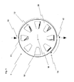
- Fig. 1 shows a first preferred embodiment of an alignment device according to the invention 1.
- the alignment device 1 shown has a plurality of containers 10.
- the containers 10 are arranged on a carousel 20.
- the containers 10 are arranged in a circle around a center M of the carousel.
- the containers 10 are arranged at regular intervals from one another.
- the angular distance from the containers 10 to each other is 45 °, so that a total of eight containers 10 are provided on the carousel.
- the containers 10 have a trapezoidal shape in the front view shown.
- the side surfaces initially extend perpendicular to a bottom surface, which is provided in the radial direction on the outside. Thereafter, the side surfaces of the container 10 are tapered in the direction of the center M.
- a closable opening 11 is provided at the radially outer bottom surface of the container 10.
- the cross section of the container in one direction into the plane of the drawing is round, preferably circular (not shown). But it can also have any other shapes that can support an alignment of the rods, such as elliptical, rectangular etc.
- elongated parts also referred to as bars 12, can be introduced into the container 10 in an inlet position 13.
- the container 10 is formed higher in a radial direction, which corresponds to a vertical direction in the inlet position of the container 10, than the length of the rods 12.
- the bottom side, so the side with the closable opening 11, is formed wider than the Length of the rods 12, so that the rods can easily lie completely on the ground side.
- the carousel 20 is rotatably disposed about the center M.
- the center M shown also corresponds to the position of a rotation axis of the carousel 20th
- a container is thus filled in the embodiment shown at an inlet position 13 with rods 12, which in only low pre-alignment are arranged in the container 10.
- rods 12 By turning the carousel 20 to the center M, here clockwise, as by the long, the carousel 20 encircling arrow in Fig. 1 is indicated, the bars 12 initially fall on one side of the container 20, which lies in a vertical direction below. The rods 12 are forced to this movement or to this tilting on one side of the container 10 solely by the acting gravitational force.
- the rods 12 then slip gradually with one of their ends on the wide bottom surface with the closable opening 11 of the container 10.
- the carousel 20 is doing a position that is a 180 ° turn or half a turn of the container 10, further rotated by a predetermined angle ⁇ in a reversing position 14. As a result, the last not yet come to rest on the floor bars fall to the ground and are thus aligned.
- the carousel 20 After reaching the reversing position, which is preferably provided at a rotational angle relative to the inlet position 13 of 225 °, the carousel 20 is rotated in the opposite direction, here counterclockwise, by the predetermined angle ⁇ back to an outlet position 15, as indicated by the curved arrow is indicated by the reversing position 14 to the outlet position 14.
- the outlet position 15 corresponds to a rotational angle relative to the inlet position 13 of 180 °, that is to say half a revolution.
- the carousel 20 is preferably not rotated continuously, but in each case to a container position.
- the next, empty container 10 can be filled at the inlet position 13 of the alignment device 1 with rods 12, while another container 10, here the diametrically opposed container 10, is emptied at the outlet position 15.
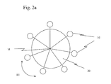
- Fig. 2 shows a second embodiment of an alignment device.
- a plurality of containers 10 on a peripheral surface of the carousel 20 preferably arranged at a regular distance.
- the carousel 20 is rotatably mounted about a central axis M, which preferably extends vertically, but may also have other upright orientations.
- the direction of rotation is in the Fig. 2a marked with the arrow R1.
- the individual container 10 in turn are mounted on a mounting axis and each rotatably provided about the mounting axis.
- the direction of rotation R2 of the container 10 is preferably perpendicular to the direction of rotation R1 of the carousel 20 (see. Fig. 2b ), but at least inclined.
- a rotation of the container 10 can take place independently of a rotation of the carousel 20.
- the attachment axes of the containers 10 may generally be coupled to the rotation of the carousel 20 or independently therefrom, for example by individual motors for the attachment axis of the containers, which may be provided in the carousel 20 or the respective container 10, for example.
- the containers may be individually rotatable.
- the orientation of the elongated parts, which are received in the containers, takes place analogously as in the first embodiment described above by rotation of the container 10 via a half turn and corresponding reverse rotation to the position of half turn.
- an alignment device 1 for aligning elongated parts 12 has at least one container 10 rotatable about an axis of rotation, wherein an orientation of the elongated parts 12 takes place by a rotation of the container 10.
- the container 10 has at least one closable opening 11 for receiving the elongated parts 12.
- the container 10 may be provided on a carousel 20.
Landscapes
- Engineering & Computer Science (AREA)
- Mechanical Engineering (AREA)
- Specific Conveyance Elements (AREA)
Priority Applications (1)
| Application Number | Priority Date | Filing Date | Title |
|---|---|---|---|
| EP12196117.1A EP2740675A1 (fr) | 2012-12-07 | 2012-12-07 | Dispositif d'orientation pour éléments longitudinaux et procédé d'alignement |
Applications Claiming Priority (1)
| Application Number | Priority Date | Filing Date | Title |
|---|---|---|---|
| EP12196117.1A EP2740675A1 (fr) | 2012-12-07 | 2012-12-07 | Dispositif d'orientation pour éléments longitudinaux et procédé d'alignement |
Publications (1)
| Publication Number | Publication Date |
|---|---|
| EP2740675A1 true EP2740675A1 (fr) | 2014-06-11 |
Family
ID=47471541
Family Applications (1)
| Application Number | Title | Priority Date | Filing Date |
|---|---|---|---|
| EP12196117.1A Withdrawn EP2740675A1 (fr) | 2012-12-07 | 2012-12-07 | Dispositif d'orientation pour éléments longitudinaux et procédé d'alignement |
Country Status (1)
| Country | Link |
|---|---|
| EP (1) | EP2740675A1 (fr) |
Cited By (1)
| Publication number | Priority date | Publication date | Assignee | Title |
|---|---|---|---|---|
| CN114538037A (zh) * | 2022-01-28 | 2022-05-27 | 南京信息职业技术学院 | 一种内六角螺钉转向装置及使用方法 |
Citations (7)
| Publication number | Priority date | Publication date | Assignee | Title |
|---|---|---|---|---|
| DE1228552B (de) * | 1962-08-20 | 1966-11-10 | Krafft & Schuell | Maschine zum Verpacken von Steck- und Naehnadeln |
| US4572374A (en) * | 1984-08-21 | 1986-02-25 | Sirotkin Karl M | Container |
| US5178256A (en) * | 1991-11-06 | 1993-01-12 | American Licorice Company | Loader machine |
| EP0548769B1 (fr) | 1991-12-20 | 1995-03-01 | Awema Ag | Installation pour la mise en ordre en vue d'un emballage de produits alimentaires longs livrés en vrac, par exemple des bâtonnets salés |
| US5636498A (en) * | 1995-05-12 | 1997-06-10 | George Gordon Associates, Inc. | Bulk straw loading system |
| DE19807775C1 (de) | 1998-02-24 | 1999-06-24 | Hastamat Verpackungstechnik Gm | Vorrichtung zum verpackungsgerechten Ordnen und/oder Portionieren von länglichem Füllgut |
| EP1876100A1 (fr) * | 2006-07-07 | 2008-01-09 | Cabinplant A/S | Appareil et procédé pour ranger un ensemble de produits alimentaires allongés |
-
2012
- 2012-12-07 EP EP12196117.1A patent/EP2740675A1/fr not_active Withdrawn
Patent Citations (7)
| Publication number | Priority date | Publication date | Assignee | Title |
|---|---|---|---|---|
| DE1228552B (de) * | 1962-08-20 | 1966-11-10 | Krafft & Schuell | Maschine zum Verpacken von Steck- und Naehnadeln |
| US4572374A (en) * | 1984-08-21 | 1986-02-25 | Sirotkin Karl M | Container |
| US5178256A (en) * | 1991-11-06 | 1993-01-12 | American Licorice Company | Loader machine |
| EP0548769B1 (fr) | 1991-12-20 | 1995-03-01 | Awema Ag | Installation pour la mise en ordre en vue d'un emballage de produits alimentaires longs livrés en vrac, par exemple des bâtonnets salés |
| US5636498A (en) * | 1995-05-12 | 1997-06-10 | George Gordon Associates, Inc. | Bulk straw loading system |
| DE19807775C1 (de) | 1998-02-24 | 1999-06-24 | Hastamat Verpackungstechnik Gm | Vorrichtung zum verpackungsgerechten Ordnen und/oder Portionieren von länglichem Füllgut |
| EP1876100A1 (fr) * | 2006-07-07 | 2008-01-09 | Cabinplant A/S | Appareil et procédé pour ranger un ensemble de produits alimentaires allongés |
Cited By (2)
| Publication number | Priority date | Publication date | Assignee | Title |
|---|---|---|---|---|
| CN114538037A (zh) * | 2022-01-28 | 2022-05-27 | 南京信息职业技术学院 | 一种内六角螺钉转向装置及使用方法 |
| CN114538037B (zh) * | 2022-01-28 | 2024-04-09 | 南京信息职业技术学院 | 一种内六角螺钉转向装置及使用方法 |
Similar Documents
| Publication | Publication Date | Title |
|---|---|---|
| DE3413234C2 (fr) | ||
| EP3077136B1 (fr) | Installation permettant de produire des cages d'armature pour des segments de mât d'éoliennes | |
| EP2868587B1 (fr) | Procédé d'emballage, dispositif d'emballage et installation de moulage par injection équipée de dispositif d'emballage | |
| DE2340390A1 (de) | Vorrichtung zum abgeben von nuessen und bonbons | |
| DE3883648T2 (de) | Misch- und Dosierapparat, z.B. Futterbehälter. | |
| DE1236844B (de) | Becherablassvorrichtung in Getraenke-Selbstverkaeufern | |
| DE102010019997A1 (de) | Maschine zum Füllen von Kapseln mit pharmazeutischen Produkten | |
| DE102007007068A1 (de) | Vorrichtung und Verfahren zum Befüllen von Behältern mit stabförmigen Produkten | |
| WO2018167054A1 (fr) | Système avec remplissage alterné de conteneurs et procédé associé | |
| DE19929180A1 (de) | Beschickungsvorrichtung für einen Schachtofen | |
| WO2018108370A1 (fr) | Dispositif support modulaire pour au moins une paire de bras préhenseurs et son procédé de montage | |
| WO2012139811A1 (fr) | Dispositif de contrôle de produits pharmaceutiques, en particulier de capsules de gélatine dure | |
| DE1947219A1 (de) | Vorrichtung zur Handhabung von Formbeschickungsmengen geschmolzenen Glases | |
| DE102007040386B4 (de) | Vorrichtung zur Montage von Kleinteilen mit verbesserter Zufuhreinrichtung | |
| DE3871959T2 (fr) | ||
| WO2018162096A1 (fr) | Dispositif de support et arbre à cames pour dispositifs de préhension | |
| EP3858766A1 (fr) | Dispositif d'alimentation, ensemble de mise à niveau pour un transporteur à vibrations, ainsi que procédé de fabrication et procédé de fonctionnement pour le dispositif d'alimentation | |
| DE69719033T2 (de) | Vorrichtung zum Überführen von Gegenständen | |
| WO2004066747A9 (fr) | Dispositif servant a inserer des batonnets dans des moules pour produire des confiseries sur batonnet | |
| EP3380420A2 (fr) | Installation et procédé permettant de séparer et/ou de contrôler des contenants | |
| DE102015009083A1 (de) | Behandlungs- und/oder Transportbehälter mit einem Klappenventil sowie Verfahren zum Entleeren eines solchen Behandlungs- und/oder Transportbehälters | |
| EP3659948B1 (fr) | Magazine et procédé de stockage dans le magazine | |
| DE69714839T2 (de) | Kombinatorischer wiegeapparat | |
| DE102020105997B4 (de) | Silo zur Lagerung von Schüttgütern | |
| DE19942494B4 (de) | Verteilervorrichtung für schüttfähige Werkstücke |
Legal Events
| Date | Code | Title | Description |
|---|---|---|---|
| PUAI | Public reference made under article 153(3) epc to a published international application that has entered the european phase |
Free format text: ORIGINAL CODE: 0009012 |
|
| 17P | Request for examination filed |
Effective date: 20121207 |
|
| AK | Designated contracting states |
Kind code of ref document: A1 Designated state(s): AL AT BE BG CH CY CZ DE DK EE ES FI FR GB GR HR HU IE IS IT LI LT LU LV MC MK MT NL NO PL PT RO RS SE SI SK SM TR |
|
| AX | Request for extension of the european patent |
Extension state: BA ME |
|
| STAA | Information on the status of an ep patent application or granted ep patent |
Free format text: STATUS: THE APPLICATION IS DEEMED TO BE WITHDRAWN |
|
| 18D | Application deemed to be withdrawn |
Effective date: 20141212 |